EP4290044A1 - Control and display device for the movement of a vertically sliding roller door - Google Patents
Control and display device for the movement of a vertically sliding roller door Download PDFInfo
- Publication number
- EP4290044A1 EP4290044A1 EP23020280.6A EP23020280A EP4290044A1 EP 4290044 A1 EP4290044 A1 EP 4290044A1 EP 23020280 A EP23020280 A EP 23020280A EP 4290044 A1 EP4290044 A1 EP 4290044A1
- Authority
- EP
- European Patent Office
- Prior art keywords
- roller shutter
- operating member
- light emitting
- emitting element
- movement
- Prior art date
- Legal status (The legal status is an assumption and is not a legal conclusion. Google has not performed a legal analysis and makes no representation as to the accuracy of the status listed.)
- Withdrawn
Links
Images

Classifications
-
- E—FIXED CONSTRUCTIONS
- E05—LOCKS; KEYS; WINDOW OR DOOR FITTINGS; SAFES
- E05F—DEVICES FOR MOVING WINGS INTO OPEN OR CLOSED POSITION; CHECKS FOR WINGS; WING FITTINGS NOT OTHERWISE PROVIDED FOR, CONCERNED WITH THE FUNCTIONING OF THE WING
- E05F15/00—Power-operated mechanisms for wings
- E05F15/60—Power-operated mechanisms for wings using electrical actuators
- E05F15/603—Power-operated mechanisms for wings using electrical actuators using rotary electromotors
- E05F15/665—Power-operated mechanisms for wings using electrical actuators using rotary electromotors for vertically-sliding wings
- E05F15/668—Power-operated mechanisms for wings using electrical actuators using rotary electromotors for vertically-sliding wings for overhead wings
-
- E—FIXED CONSTRUCTIONS
- E06—DOORS, WINDOWS, SHUTTERS, OR ROLLER BLINDS IN GENERAL; LADDERS
- E06B—FIXED OR MOVABLE CLOSURES FOR OPENINGS IN BUILDINGS, VEHICLES, FENCES OR LIKE ENCLOSURES IN GENERAL, e.g. DOORS, WINDOWS, BLINDS, GATES
- E06B9/00—Screening or protective devices for wall or similar openings, with or without operating or securing mechanisms; Closures of similar construction
- E06B9/56—Operating, guiding or securing devices or arrangements for roll-type closures; Spring drums; Tape drums; Counterweighting arrangements therefor
- E06B9/68—Operating devices or mechanisms, e.g. with electric drive
-
- E—FIXED CONSTRUCTIONS
- E05—LOCKS; KEYS; WINDOW OR DOOR FITTINGS; SAFES
- E05F—DEVICES FOR MOVING WINGS INTO OPEN OR CLOSED POSITION; CHECKS FOR WINGS; WING FITTINGS NOT OTHERWISE PROVIDED FOR, CONCERNED WITH THE FUNCTIONING OF THE WING
- E05F15/00—Power-operated mechanisms for wings
- E05F15/40—Safety devices, e.g. detection of obstructions or end positions
-
- G—PHYSICS
- G08—SIGNALLING
- G08B—SIGNALLING SYSTEMS, e.g. PERSONAL CALLING SYSTEMS; ORDER TELEGRAPHS; ALARM SYSTEMS
- G08B5/00—Visible signalling systems, e.g. visible personal calling systems or remote indication of seats occupied
- G08B5/22—Visible signalling systems, e.g. visible personal calling systems or remote indication of seats occupied using electric transmission; using electromagnetic transmission
- G08B5/36—Visible signalling systems, e.g. visible personal calling systems or remote indication of seats occupied using electric transmission; using electromagnetic transmission using visible light sources
- G08B5/38—Visible signalling systems, e.g. visible personal calling systems or remote indication of seats occupied using electric transmission; using electromagnetic transmission using visible light sources using flashing light
-
- E—FIXED CONSTRUCTIONS
- E05—LOCKS; KEYS; WINDOW OR DOOR FITTINGS; SAFES
- E05Y—INDEXING SCHEME ASSOCIATED WITH SUBCLASSES E05D AND E05F, RELATING TO CONSTRUCTION ELEMENTS, ELECTRIC CONTROL, POWER SUPPLY, POWER SIGNAL OR TRANSMISSION, USER INTERFACES, MOUNTING OR COUPLING, DETAILS, ACCESSORIES, AUXILIARY OPERATIONS NOT OTHERWISE PROVIDED FOR, APPLICATION THEREOF
- E05Y2400/00—Electronic control; Electrical power; Power supply; Power or signal transmission; User interfaces
- E05Y2400/10—Electronic control
- E05Y2400/52—Safety arrangements associated with the wing motor
-
- E—FIXED CONSTRUCTIONS
- E05—LOCKS; KEYS; WINDOW OR DOOR FITTINGS; SAFES
- E05Y—INDEXING SCHEME ASSOCIATED WITH SUBCLASSES E05D AND E05F, RELATING TO CONSTRUCTION ELEMENTS, ELECTRIC CONTROL, POWER SUPPLY, POWER SIGNAL OR TRANSMISSION, USER INTERFACES, MOUNTING OR COUPLING, DETAILS, ACCESSORIES, AUXILIARY OPERATIONS NOT OTHERWISE PROVIDED FOR, APPLICATION THEREOF
- E05Y2400/00—Electronic control; Electrical power; Power supply; Power or signal transmission; User interfaces
- E05Y2400/65—Power or signal transmission
- E05Y2400/66—Wireless transmission
-
- E—FIXED CONSTRUCTIONS
- E06—DOORS, WINDOWS, SHUTTERS, OR ROLLER BLINDS IN GENERAL; LADDERS
- E06B—FIXED OR MOVABLE CLOSURES FOR OPENINGS IN BUILDINGS, VEHICLES, FENCES OR LIKE ENCLOSURES IN GENERAL, e.g. DOORS, WINDOWS, BLINDS, GATES
- E06B9/00—Screening or protective devices for wall or similar openings, with or without operating or securing mechanisms; Closures of similar construction
- E06B9/56—Operating, guiding or securing devices or arrangements for roll-type closures; Spring drums; Tape drums; Counterweighting arrangements therefor
- E06B9/68—Operating devices or mechanisms, e.g. with electric drive
- E06B2009/6809—Control
Definitions
- the present invention generally refers to vertically sliding doors for industrial use, in which opening and closing of a passage formed in a wall and delimited by a portal structure takes place with a relatively high speed.
- the invention refers to a vertically sliding roller door comprising a portal structure which defines a pair of opposing vertical guide rails for guiding the sliding of lateral edges of a roller shutter for closing the door, for the purpose of allowing vertical upward and downward movements of the roller shutter with respect to the portal structure, a shelter area for the roller shutter wound up in the open condition of the door being defined above the portal structure.
- the invention relates to a device for controlling and displaying the movement of a rapidly vertically sliding roll-up door as defined in the preamble of the annexed claim 1, for the purpose of making access by a user through such a door easier and more immediate.
- a device for controlling and displaying the movement of a rapidly vertically sliding roll-up door as defined in the preamble of the annexed claim 1, for the purpose of making access by a user through such a door easier and more immediate.
- the main object of the present invention is to propose a rapid vertical sliding roller shutter door which is provided with a device for controlling the attitude of the roller shutter, particularly during the steps of ascent, of standing in the open condition, and of descent, provided with at least an operating member which allows the instantaneous attitude of the roller shutter to be displayed promptly and clearly to inform a user if it is moving, in which case the crossing of the portal structure is precluded, or if the roller shutter is in the open and stationary configuration, in which case the portal structure can be crossed freely.
- said at least one operating member incorporates means for emitting signals indicative of an instantaneous attitude of the roller shutter
- the device comprises an electronic control unit connected to said at least one operating member, to the means for emitting signals of each operating member, to said motorized means and to means for detecting an instantaneous attitude of the rolling shutter, for the purpose of activating said motorized means and of emitting a signal indicative of an instantaneous attitude of the shutter through said at least one operating member.
- the device of the invention makes it possible to control the operation of the sliding door and to immediately display the attitude condition of the roller shutter to allow a user to cross the portal structure free of the roller shutter in complete safety.
- each operating member consists of a push-button switch of the normally open type.
- the operating member or members of the device of the invention has or have a simple and inexpensive structure, and they are easily available on the market, to the full advantage of the cheapness of the device.
- said at least one operating member has an outer covering of a transparent or semi-transparent material
- said means for emitting signals indicative of an instantaneous attitude of the roller shutter consist of at least one light emitting element incorporated in each operating member.
- the device of the invention allows a user to be visually informed of the instantaneous configuration of the roller shutter.
- said at least one operating member comprises a pair of emitting elements of light having different wavelengths, which are intended to be operated individually and separately for different attitude conditions of the roller shutter, a first light emitting element being able to be activated during a vertical movement of the roller shutter, and a second light emitting element being able to be activated when the roller shutter is in its raised stationary configuration.
- a roll-up door indicated as a whole by the reference numeral 10, comprises a portal structure 12 associated with a generally rectangular passage opening 14 formed in a wall of a building.
- the opening 14, which is delimited sideways by a pair of vertical and parallel uprights 16 and, in the vertical direction, by an upper crosspiece 18 and by a lower base plane 19, can be closed by means of a roller shutter 20 which can consist of a flexible curtain of plastic material such as PVC, polyethylene or polyurethane, or of a plasticized textile material, usually having a thickness of the order of a millimeter or a few millimeters, or of a roller shutter consisting of a series of elongated panels or slats arranged perpendicularly to the uprights 16 and articulated with each other.
- a roller shutter 20 which can consist of a flexible curtain of plastic material such as PVC, polyethylene or polyurethane, or of a plasticized textile material, usually having a thickness of the order of a millimeter or a few mill
- roller shutter 20 slidably engage guide rails 24 formed along the uprights 16, whereby the roller shutter 20 is movable between a closed configuration, or lowered relative to the lower plane 19, in which it closes the opening 14, and an open configuration, or raised with respect to the lower surface 19, in which the opening 14 is free.
- a shelter area 22 for the rolling shutter 20 for example in its configuration wrapped around a central shaft (not shown in the drawings as it is of a known per se type) parallel to the crosspiece 18 and mounted rotatably about its own axis, which constitutes driving means of the roller shutter 20, or according to a spirally wound configuration with its lateral edges slidingly engaged in spiral-shaped guide grooves (not shown) that extends from the top of the guide rails 24, in which case the roller shutter 20 is operated by driving means in the form of toothed wheels which engage areas adjacent to its lateral edges, the rotation of which drags the roller shutter 20 by friction.
- the movement of the roller shutter 20 takes place due to the aforesaid driving means which are controlled by motorized means including an electric motor 26 (shown schematically in Figure 5 ), usually supported directly by the portal structure 12 and incorporated in the shelter area 22.
- motorized means including an electric motor 26 (shown schematically in Figure 5 ), usually supported directly by the portal structure 12 and incorporated in the shelter area 22.
- the motor 26 is operated by at least one operating member 28 having a movable part, consisting of a spring-loaded button switch of the normally open type, i.e. of the type capable of closing a circuit as a result of its compression, arranged on an upright 16.
- the operating member 28 is able to generate, as a result of its manual actuation, an activation signal for the engine 26 through an electronic control unit ECU which will be referred to in greater detail below.
- the device of the invention comprises two identical operating members 28, each arranged at the same front side of a respective upright 16 of the structure 12.
- Each operating member 28 is provided with an outer covering 28a of a transparent or semi-transparent material, and incorporates at least one light emitting element intended to light up as a result of its compression.
- the aforementioned light emitting element lights up as a result of the detection of a particular operating condition of the roller shutter 20, such as a state of movement or stop of the roller shutter 20 in the open condition, for the purpose of signaling to a user the possibility of crossing the opening 14 of the portal structure 12.
- the electronic control unit ECU is connected to each operating member 28 so as to receive from at least one of them a signal generated by the compression thereof, to the electric motor 26 for controlling its actuation according to one direction of rotation or another, and to at least one light emitting element incorporated in the respective operating member 28, which will be referred to in greater detail below.
- the ECU unit is capable of activating the at least one light emitting element of each operating member 28 as a function of the detection of the instantaneous attitude condition of the rolling shutter 20.
- This instantaneous attitude condition of the roller shutter 20 can be ascertained by means of detection means of the attitude of the roller shutter 20 connected to the control unit ECU, represented schematically and by way of example in Figure 5 by means of a pair of position sensors indicated generically S 1 , S 2 , respectively upper and lower, capable of signaling the achievement of the upper and lower end-of-stroke configurations, i.e. of opening and closing, of the roller shutter 20 with respect to the portal structure 12.
- the sensor means can consist of one or more sensors incorporated in the motor 26 and adapted to recognize, upon reaching one of the aforementioned end-of-stroke configurations, the occurrence of a resistance against a further rotation of the motor 26, or of a single sensor capable of detecting an upper or lower stop of the movement of the rolling shutter 20.
- Each operating member 28 preferably contains two separate light emitting elements, respectively indicated by reference numerals 30 and 32, each of which conveniently consists of a LED, the emitting elements 30 and 32 being able to emit light having a different wavelength and intended to be actuated individually in response to different attitude conditions of the roller shutter 20 identified by the means for detecting the instantaneous attitude of the roller shutter 20 referred to above.
- the light emitting elements 30 and 32 allow a light signal correlated with the relative instantaneous condition of the rolling shutter 20 to be displayed at each operating member 28.
- the first light emitting element 30 is activated by the ECU unit when the roller shutter 20 is subject to a vertical upward or downward movement, while the second light emitting element 32 is activated when the roller shutter 20 is in the fully raised and stationary condition, i.e. when the roll-up door 10 is in its open configuration.
- the first light emitting element 30 is a LED which emits a visible red light, conveniently according to a flashing mode, to signal that the roller shutter 20 is moving and that it is not allowed to pass through the opening 14 of the portal structure 12.
- the second light emitting element 32 is a LED which emits a continuous visible green or blue light to signal that the roller shutter 20 is in the fully raised configuration in which it is allowed to pass through the opening 14 of the portal structure 12.
- the compression applied to the operating member 28 generates an electric impulse which is transmitted to the unit ECU according to the direction of arrow D of Figure 5 ; this impulse causes the emission of a signal by the unit ECU according to the arrow G, which controls the operation of the electric motor 26 to cause, in the considered situation, an upward movement of the roller shutter 20 along the direction indicated by arrow B of Figure 2 .
- the unit ECU simultaneously receives via the sensor means S 1 , S 2 , an information relating to the instantaneous attitude of the roller shutter 20, which in this case is subject to an upward movement, and activates the first light emitting element 30 of both the operating elements 28 via a signal identified by the arrow E of Figure 5 .
- the elements 30 emit a visual signaling through the transparent or semi-transparent covering 28a of the operating elements 28, which preferably consists of a flashing red light, outlined in Figure 2 by a series of radial dotted lines extending from the members 28, to provide the signaling that, since the roller shutter 20 is moving, crossing the opening 14 of the structure 12 is not allowed.
- the sensor means S 1 , S 2 signal to the unit ECU that the roller shutter 20 has reached its raised configuration, and the same unit ECU emits a signal indicated by arrow G of Figure 5 to stop the engine 26.
- the unit ECU informed by the sensor means S 1 , S 2 of the fact that the roller shutter 20 is in its raised and stationary configuration, deactivates the first light emitting element 30 of the members 28 through a signal directed according to the arrow E of Figure 5 , and emits a signal indicated by arrow F of the same Figure to activate the second light emitting element 32 of the members 28.
- the second emitting elements 32 emit, through their own transparent or semi-transparent covering 28a, a visual signaling which preferably consists of a continuous green or blue light, schematically represented in Figure 3 by a series of continuous rays coming from the members 28, to provide the signaling that, since the roller shutter 20 is in its raised stationary configuration, crossing of the opening 14 of the structure 12 is allowed.
- a visual signaling which preferably consists of a continuous green or blue light, schematically represented in Figure 3 by a series of continuous rays coming from the members 28, to provide the signaling that, since the roller shutter 20 is in its raised stationary configuration, crossing of the opening 14 of the structure 12 is allowed.
- the duration of the opening step of the rolling shutter 20 can be set as desired by means of a timer unit (not shown) of the unit ECU and can normally last for a time varying between 5 and 15 s.
- the unit ECU At the end of the duration set in the timer unit of the unit ECU for the stationary and raised step of the rolling shutter 20, the unit ECU emits an actuation impulse towards the motor 26, as indicated by arrow G of Figure 5 , according to a direction of rotation opposite to the upward rotation of the roller shutter 20, causing a movement of the roller shutter 20 in the direction indicated by arrow C of Figure 4 .
- the sensor means S 1 , S 2 inform the unit ECU that the roller shutter 20 is moving, whereby the unit ECU deactivates the second light emitting elements 32 of the members 28 and emits a signal indicated by arrow E of Figure 5 to activate the first light emitting elements 30 again, to emit the visual signaling which preferably consists of a flashing red light outlined in Figure 4 with a series of dashed rays, so as to inform a user that crossing the opening 14 of the portal structure 12 is not allowed since the rolling shutter 20 is moving.
- the ECU unit When the roller shutter 20, at the end of the descent step, reaches the completely lowered configuration represented in Figure 1 , the ECU unit emits a signal to the motor 26 to stop it and simultaneously deactivates the light emitting element 30, so that the switching members 28 are turned off.
Landscapes
- Physics & Mathematics (AREA)
- Engineering & Computer Science (AREA)
- Structural Engineering (AREA)
- Electromagnetism (AREA)
- General Physics & Mathematics (AREA)
- Architecture (AREA)
- Civil Engineering (AREA)
- Operating, Guiding And Securing Of Roll- Type Closing Members (AREA)
Abstract
Description
- The present invention generally refers to vertically sliding doors for industrial use, in which opening and closing of a passage formed in a wall and delimited by a portal structure takes place with a relatively high speed.
- More specifically, the invention refers to a vertically sliding roller door comprising a portal structure which defines a pair of opposing vertical guide rails for guiding the sliding of lateral edges of a roller shutter for closing the door, for the purpose of allowing vertical upward and downward movements of the roller shutter with respect to the portal structure, a shelter area for the roller shutter wound up in the open condition of the door being defined above the portal structure.
- More specifically, the invention relates to a device for controlling and displaying the movement of a rapidly vertically sliding roll-up door as defined in the preamble of the annexed claim 1, for the purpose of making access by a user through such a door easier and more immediate. In fact, especially in the case of vertically sliding roller doors with a high extension in height, it can be impractical and sometimes difficult for a user at ground level to monitor the variations in the position of the roller shutter before or during crossing it, since there is the risk that the user may be at the portal structure when the roller shutter is about to start a movement step, particularly a descent step.
- The main object of the present invention is to propose a rapid vertical sliding roller shutter door which is provided with a device for controlling the attitude of the roller shutter, particularly during the steps of ascent, of standing in the open condition, and of descent, provided with at least an operating member which allows the instantaneous attitude of the roller shutter to be displayed promptly and clearly to inform a user if it is moving, in which case the crossing of the portal structure is precluded, or if the roller shutter is in the open and stationary configuration, in which case the portal structure can be crossed freely.
- This object is achieved by the invention by virtue of the fact that said at least one operating member incorporates means for emitting signals indicative of an instantaneous attitude of the roller shutter, and of the fact that the device comprises an electronic control unit connected to said at least one operating member, to the means for emitting signals of each operating member, to said motorized means and to means for detecting an instantaneous attitude of the rolling shutter, for the purpose of activating said motorized means and of emitting a signal indicative of an instantaneous attitude of the shutter through said at least one operating member.
- By virtue of these features, the device of the invention makes it possible to control the operation of the sliding door and to immediately display the attitude condition of the roller shutter to allow a user to cross the portal structure free of the roller shutter in complete safety.
- According to a preferred feature of the invention, each operating member consists of a push-button switch of the normally open type. In this manner, the operating member or members of the device of the invention has or have a simple and inexpensive structure, and they are easily available on the market, to the full advantage of the cheapness of the device.
- According to another preferred feature of the invention, said at least one operating member has an outer covering of a transparent or semi-transparent material, and said means for emitting signals indicative of an instantaneous attitude of the roller shutter consist of at least one light emitting element incorporated in each operating member.
- In this manner, the device of the invention allows a user to be visually informed of the instantaneous configuration of the roller shutter.
- According to yet another preferred feature of the invention, said at least one operating member comprises a pair of emitting elements of light having different wavelengths, which are intended to be operated individually and separately for different attitude conditions of the roller shutter, a first light emitting element being able to be activated during a vertical movement of the roller shutter, and a second light emitting element being able to be activated when the roller shutter is in its raised stationary configuration. This makes it possible to effectively and immediately display an instantaneous condition of the attitude of the roller shutter.
- Further characteristics and advantages of the invention will become clearer from the following detailed description provided by way of nonlimiting example and referred to the attached drawings in which:
-
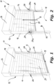
Figure 1 is a schematic perspective view of a high-speed roller shutter door in its closed condition corresponding to the fully lowered configuration of the roller shutter, in which the device of the invention can be activated, -
Figure 2 is a view similar toFigure 1 , in which the roller shutter begins an ascent movement as a result of the activation of the device of the invention, -
Figure 3 is a view similar toFigure 2 with the roller shutter in the fully raised configuration, in which passing through the portal structure of the sliding door is permitted, -
Figure 4 is a view similar toFigure 3 , in which the roller shutter is animated by a downward movement, and -
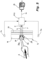
Figure 5 is a diagrammatic view schematically showing the main elements of the device of the invention. - With reference to the drawings, a roll-up door, indicated as a whole by the
reference numeral 10, comprises aportal structure 12 associated with a generallyrectangular passage opening 14 formed in a wall of a building. The opening 14, which is delimited sideways by a pair of vertical andparallel uprights 16 and, in the vertical direction, by anupper crosspiece 18 and by alower base plane 19, can be closed by means of aroller shutter 20 which can consist of a flexible curtain of plastic material such as PVC, polyethylene or polyurethane, or of a plasticized textile material, usually having a thickness of the order of a millimeter or a few millimeters, or of a roller shutter consisting of a series of elongated panels or slats arranged perpendicularly to theuprights 16 and articulated with each other. The side edges of theroller shutter 20 slidably engageguide rails 24 formed along theuprights 16, whereby theroller shutter 20 is movable between a closed configuration, or lowered relative to thelower plane 19, in which it closes theopening 14, and an open configuration, or raised with respect to thelower surface 19, in which theopening 14 is free. - Above the
crosspiece 18 of theportal structure 12 there is ashelter area 22 for therolling shutter 20, for example in its configuration wrapped around a central shaft (not shown in the drawings as it is of a known per se type) parallel to thecrosspiece 18 and mounted rotatably about its own axis, which constitutes driving means of theroller shutter 20, or according to a spirally wound configuration with its lateral edges slidingly engaged in spiral-shaped guide grooves (not shown) that extends from the top of theguide rails 24, in which case theroller shutter 20 is operated by driving means in the form of toothed wheels which engage areas adjacent to its lateral edges, the rotation of which drags theroller shutter 20 by friction. - In both the cases mentioned above, the movement of the
roller shutter 20 takes place due to the aforesaid driving means which are controlled by motorized means including an electric motor 26 (shown schematically inFigure 5 ), usually supported directly by theportal structure 12 and incorporated in theshelter area 22. - The
motor 26 is operated by at least oneoperating member 28 having a movable part, consisting of a spring-loaded button switch of the normally open type, i.e. of the type capable of closing a circuit as a result of its compression, arranged on an upright 16. Theoperating member 28 is able to generate, as a result of its manual actuation, an activation signal for theengine 26 through an electronic control unit ECU which will be referred to in greater detail below. - Preferably, and as shown in
Figures 1 to 4 , the device of the invention comprises twoidentical operating members 28, each arranged at the same front side of a respective upright 16 of thestructure 12. - Each
operating member 28 is provided with anouter covering 28a of a transparent or semi-transparent material, and incorporates at least one light emitting element intended to light up as a result of its compression. In particular, the aforementioned light emitting element lights up as a result of the detection of a particular operating condition of theroller shutter 20, such as a state of movement or stop of theroller shutter 20 in the open condition, for the purpose of signaling to a user the possibility of crossing theopening 14 of theportal structure 12. - The electronic control unit ECU is connected to each
operating member 28 so as to receive from at least one of them a signal generated by the compression thereof, to theelectric motor 26 for controlling its actuation according to one direction of rotation or another, and to at least one light emitting element incorporated in therespective operating member 28, which will be referred to in greater detail below. The ECU unit is capable of activating the at least one light emitting element of eachoperating member 28 as a function of the detection of the instantaneous attitude condition of therolling shutter 20. - This instantaneous attitude condition of the
roller shutter 20 can be ascertained by means of detection means of the attitude of theroller shutter 20 connected to the control unit ECU, represented schematically and by way of example inFigure 5 by means of a pair of position sensors indicated generically S1, S2, respectively upper and lower, capable of signaling the achievement of the upper and lower end-of-stroke configurations, i.e. of opening and closing, of theroller shutter 20 with respect to theportal structure 12. As an alternative, the sensor means can consist of one or more sensors incorporated in themotor 26 and adapted to recognize, upon reaching one of the aforementioned end-of-stroke configurations, the occurrence of a resistance against a further rotation of themotor 26, or of a single sensor capable of detecting an upper or lower stop of the movement of therolling shutter 20. - Each
operating member 28 preferably contains two separate light emitting elements, respectively indicated byreference numerals emitting elements roller shutter 20 identified by the means for detecting the instantaneous attitude of theroller shutter 20 referred to above. Thelight emitting elements rolling shutter 20 to be displayed at eachoperating member 28. - In particular, the first
light emitting element 30 is activated by the ECU unit when theroller shutter 20 is subject to a vertical upward or downward movement, while the secondlight emitting element 32 is activated when theroller shutter 20 is in the fully raised and stationary condition, i.e. when the roll-updoor 10 is in its open configuration. - Preferably, the first
light emitting element 30 is a LED which emits a visible red light, conveniently according to a flashing mode, to signal that theroller shutter 20 is moving and that it is not allowed to pass through theopening 14 of theportal structure 12. Still preferably, the secondlight emitting element 32 is a LED which emits a continuous visible green or blue light to signal that theroller shutter 20 is in the fully raised configuration in which it is allowed to pass through theopening 14 of theportal structure 12. - In the operation of the device of the invention, starting from the closed configuration of the
roller shutter door 10 shown inFigure 1 in which theroller shutter 20 is in the fully lowered condition with its lower end portion or slat in contact with thelower base plane 19, both thelight emitting elements operating member 28 to a compression by manual action, for example by means of a finger, in the direction indicated by arrow A ofFigures 1 and5 . - The compression applied to the
operating member 28 generates an electric impulse which is transmitted to the unit ECU according to the direction of arrow D ofFigure 5 ; this impulse causes the emission of a signal by the unit ECU according to the arrow G, which controls the operation of theelectric motor 26 to cause, in the considered situation, an upward movement of theroller shutter 20 along the direction indicated by arrow B ofFigure 2 . - The unit ECU simultaneously receives via the sensor means S1, S2, an information relating to the instantaneous attitude of the
roller shutter 20, which in this case is subject to an upward movement, and activates the firstlight emitting element 30 of both theoperating elements 28 via a signal identified by the arrow E ofFigure 5 . Theelements 30 emit a visual signaling through the transparent or semi-transparent covering 28a of theoperating elements 28, which preferably consists of a flashing red light, outlined inFigure 2 by a series of radial dotted lines extending from themembers 28, to provide the signaling that, since theroller shutter 20 is moving, crossing the opening 14 of thestructure 12 is not allowed. - At the end of the raising step of the
roller shutter 20, shown inFigure 3 , the sensor means S1, S2 signal to the unit ECU that theroller shutter 20 has reached its raised configuration, and the same unit ECU emits a signal indicated by arrow G ofFigure 5 to stop theengine 26. Simultaneously, the unit ECU, informed by the sensor means S1, S2 of the fact that theroller shutter 20 is in its raised and stationary configuration, deactivates the firstlight emitting element 30 of themembers 28 through a signal directed according to the arrow E ofFigure 5 , and emits a signal indicated by arrow F of the same Figure to activate the secondlight emitting element 32 of themembers 28. - The
second emitting elements 32 emit, through their own transparent or semi-transparent covering 28a, a visual signaling which preferably consists of a continuous green or blue light, schematically represented inFigure 3 by a series of continuous rays coming from themembers 28, to provide the signaling that, since theroller shutter 20 is in its raised stationary configuration, crossing of the opening 14 of thestructure 12 is allowed. - The duration of the opening step of the rolling
shutter 20 can be set as desired by means of a timer unit (not shown) of the unit ECU and can normally last for a time varying between 5 and 15 s. - At the end of the duration set in the timer unit of the unit ECU for the stationary and raised step of the
rolling shutter 20, the unit ECU emits an actuation impulse towards themotor 26, as indicated by arrow G ofFigure 5 , according to a direction of rotation opposite to the upward rotation of theroller shutter 20, causing a movement of theroller shutter 20 in the direction indicated by arrow C ofFigure 4 . - Simultaneously, the sensor means S1, S2 inform the unit ECU that the
roller shutter 20 is moving, whereby the unit ECU deactivates the secondlight emitting elements 32 of themembers 28 and emits a signal indicated by arrow E ofFigure 5 to activate the firstlight emitting elements 30 again, to emit the visual signaling which preferably consists of a flashing red light outlined inFigure 4 with a series of dashed rays, so as to inform a user that crossing the opening 14 of theportal structure 12 is not allowed since therolling shutter 20 is moving. - When the
roller shutter 20, at the end of the descent step, reaches the completely lowered configuration represented inFigure 1 , the ECU unit emits a signal to themotor 26 to stop it and simultaneously deactivates thelight emitting element 30, so that theswitching members 28 are turned off.
Claims (9)
- Control device for controlling and displaying the movement of a rapid vertical sliding roll-up door, which door comprises a portal structure (12) including a pair of uprights (16) which define respective opposite guide rails (24) to guide the sliding of opposite lateral edges of a roller shutter (20) for closing the door, and an upper crosspiece (18) delimiting a shelter area (22) for the roller shutter (20) in the open condition of the door, the movement of the roller shutter (20) with respect to said portal structure (12) being controlled by motorized control means (26) of the movement of the roller shutter (20), which can be controlled by means of at least one movable operating member (28) adapted to generate an activation signal of said motorized means (26),
characterized in that said at least one operating member (28) incorporates means (30, 32) for emitting signals indicative of an instantaneous attitude of the roller shutter (20), and in that the device comprises an electronic control unit (ECU) connected to said at least one operating member (28), to the means (30, 32) for emitting signals of each operating member (28), to said motorized means (26) and to means for detecting an instantaneous attitude of the roller shutter (20), for the purpose of activating said motorized means (26) and of emitting a signal indicative of an instantaneous attitude of the roller shutter (20) through said at least one operating member (28). - Device according to claim 1, characterized in that each operating member (28) consists of a push button switch of the normally open type.
- Device according to claim 1 or 2, characterized in that said at least one operating member (28) has an outer covering (28a) of a transparent or semi-transparent material, and in that said means (30, 32) for emitting signals indicative of an instantaneous attitude of the roller shutter (20) consist of at least one light emitting element (30, 32) incorporated in each operating member (28).
- Device according to claim 3, characterized in that said at least one operating member (28) comprises a pair of emitting elements (30, 32) of light having different wavelengths, which are intended to be operated individually and separately for different attitude conditions of the roller shutter (20), a first light emitting element (30) being able to be activated during a vertical movement of the roller shutter (20), and a second light emitting element (32) being able to be activated when the roller shutter (20) is in its stationary raised configuration.
- Device according to claim 4, characterized in that said at least one operating member (28) comprises a first light emitting element (30), preferably red in color, intended to be operated during a vertical movement of the roller shutter (20), and a second light emitting element (32), preferably green or blue in color, intended to be operated when the roller shutter (20) is in its stationary raised configuration.
- Device according to claim 5, characterized in that the first light emitting element (30) is activated according to a flashing mode.
- Device according to any one of claims 1 to 6, characterized in that said motorized means consist of an electric motor (26) associated with means for dragging the roller shutter (20) in the form of a rotating shaft that extends into said shelter area (22) of the roller shutter (20) parallel to the upper crosspiece (18) of the portal structure (12), or in the form of friction dragging means of the roller shutter (20) adapted for engaging areas of the roller shutter (20) adjacent to its lateral edges which engage, in said shelter area (22), spiral-shaped guide grooves connected to the guide rails (24) of the uprights (16) of the portal structure (12).
- Device according to any one of claims 1 to 7, characterized in that it comprises a pair of operating members (28), each arranged on a respective upright (16) of the portal structure (12) .
- Device according to any one of claims 1 to 8, characterized in that the electronic control unit (ECU) comprises a timer unit for setting the duration of the open configuration of the roller shutter (20).
Applications Claiming Priority (1)
| Application Number | Priority Date | Filing Date | Title |
|---|---|---|---|
| IT102022000012134A IT202200012134A1 (en) | 2022-06-08 | 2022-06-08 | Device for controlling and displaying the movement of a rapid vertical sliding roller door |
Publications (1)
| Publication Number | Publication Date |
|---|---|
| EP4290044A1 true EP4290044A1 (en) | 2023-12-13 |
Family
ID=83188587
Family Applications (1)
| Application Number | Title | Priority Date | Filing Date |
|---|---|---|---|
| EP23020280.6A Withdrawn EP4290044A1 (en) | 2022-06-08 | 2023-06-06 | Control and display device for the movement of a vertically sliding roller door |
Country Status (3)
| Country | Link |
|---|---|
| US (1) | US20230417098A1 (en) |
| EP (1) | EP4290044A1 (en) |
| IT (1) | IT202200012134A1 (en) |
Citations (3)
| Publication number | Priority date | Publication date | Assignee | Title |
|---|---|---|---|---|
| US20200115948A1 (en) * | 2014-08-06 | 2020-04-16 | Rite-Hite Holding Corporation | Methods and Systems to Indicate the Status of Door Operations |
| US20200199928A1 (en) * | 2018-12-21 | 2020-06-25 | Rytec Corporation | Safety system and method for overhead roll-up doors |
| US20210241555A1 (en) * | 2018-04-26 | 2021-08-05 | Douglass Technologies, Llc | Door opener display controller, systems and methods |
Family Cites Families (21)
| Publication number | Priority date | Publication date | Assignee | Title |
|---|---|---|---|---|
| US6737821B1 (en) * | 1991-04-09 | 2004-05-18 | The Chamberlain Group, Inc. | Barrier operator with fault control |
| US6598648B1 (en) * | 1999-03-12 | 2003-07-29 | Rite-Hite Holding Corporation | Industrial door system responsive to an impact |
| US20030102836A1 (en) * | 2000-08-31 | 2003-06-05 | Mccall Steve | Safety garage door retrofit system |
| US6469464B1 (en) * | 2000-08-31 | 2002-10-22 | Mccall Steve | Automatic safety garage door closer |
| US7034682B2 (en) * | 2003-06-20 | 2006-04-25 | Rite-Hite Holding Corporation | Door with a safety antenna |
| ITTV20050055A1 (en) * | 2005-04-22 | 2006-10-23 | Nice Spa | LUMINOUS DEVICE. |
| US20070277943A1 (en) * | 2006-06-05 | 2007-12-06 | Rite-Hite Holding Corporation | Track and guide system for a door |
| US8014966B2 (en) * | 2006-06-23 | 2011-09-06 | Overhead Door Corporation | Calibration and setup unit for barrier operator control system |
| US20080022596A1 (en) * | 2006-07-27 | 2008-01-31 | Boerger James C | Door signaling system |
| US7862209B2 (en) * | 2008-01-09 | 2011-01-04 | The Chamberlain Group, Inc. | Permanently installed light emitting elements for a barrier operator |
| US8279040B2 (en) * | 2008-10-07 | 2012-10-02 | The Chamberlain Group, Inc. | System and method for control of multiple barrier operators |
| US9163446B2 (en) * | 2010-03-17 | 2015-10-20 | Yale Security Inc. | Door control apparatus |
| CA2854641C (en) * | 2011-10-31 | 2019-06-04 | Automatic Technology (Australia) Pty Ltd | Safety system for moveable closures |
| US9574387B2 (en) * | 2014-11-21 | 2017-02-21 | The Chamberlain Group, Inc. | Alignment of obstacle detection components |
| US10970954B2 (en) * | 2018-09-07 | 2021-04-06 | The Chamberlain Group, Inc. | Movable barrier operator registration verification |
| CA3060816C (en) * | 2018-11-02 | 2022-02-01 | Gregory Ion | Door control system |
| US11261648B2 (en) * | 2019-12-20 | 2022-03-01 | The Chamberlain Group Llc | Movable barrier disengagement detection |
| US11846131B2 (en) * | 2020-01-15 | 2023-12-19 | Jeffrey Peter Martinez | Door status monitoring system |
| US11610444B2 (en) * | 2020-12-22 | 2023-03-21 | The Chamberlain Group Llc | Movable barrier operator system having an imminent motion notification apparatus |
| CN117651795A (en) * | 2021-05-07 | 2024-03-05 | 瑞泰控股公司 | Methods and devices for monitoring and/or adjusting door operation |
| WO2022251558A1 (en) * | 2021-05-27 | 2022-12-01 | The Chamberlain Group Llc | Security system for a moveable barrier operator |
-
2022
- 2022-06-08 IT IT102022000012134A patent/IT202200012134A1/en unknown
-
2023
- 2023-06-06 US US18/206,480 patent/US20230417098A1/en not_active Abandoned
- 2023-06-06 EP EP23020280.6A patent/EP4290044A1/en not_active Withdrawn
Patent Citations (3)
| Publication number | Priority date | Publication date | Assignee | Title |
|---|---|---|---|---|
| US20200115948A1 (en) * | 2014-08-06 | 2020-04-16 | Rite-Hite Holding Corporation | Methods and Systems to Indicate the Status of Door Operations |
| US20210241555A1 (en) * | 2018-04-26 | 2021-08-05 | Douglass Technologies, Llc | Door opener display controller, systems and methods |
| US20200199928A1 (en) * | 2018-12-21 | 2020-06-25 | Rytec Corporation | Safety system and method for overhead roll-up doors |
Non-Patent Citations (3)
| Title |
|---|
| ANONYMOUS: "Anleitung für Montage, Betrieb und Wartung Steuerung 360", HÖRMANN KG VERKAUFSGESELLSCHAFT, 1 November 2017 (2017-11-01), pages 1 - 84, XP093208625 |
| BMP EUROPE GROUP: "NEW ACCESSORY - Safety LED light + Push button", 10 February 2022 (2022-02-10), XP093228281, Retrieved from the Internet <URL:https://www.youtube.com/watch?v=a0SfFIiGw3g> [retrieved on 20241126] * |
| BMP EUROPE GROUP: "NEW ACCESSORY - Safety LED light + Push button", YOUTUBE, 10 February 2022 (2022-02-10), XP093208605, Retrieved from the Internet <URL:https://www.youtube.com/watch?v=a0SfFIiGw3g> |
Also Published As
| Publication number | Publication date |
|---|---|
| IT202200012134A1 (en) | 2023-12-08 |
| US20230417098A1 (en) | 2023-12-28 |
Similar Documents
| Publication | Publication Date | Title |
|---|---|---|
| US4386398A (en) | Automatic door control apparatus | |
| JP2017095940A (en) | Opening/closing device and opening/closing control method | |
| US12404714B2 (en) | System and method for safety management in roll-up doors | |
| CN111810039B (en) | Method for treating resistance of roller shutter door and window | |
| JP7333152B2 (en) | Obstacle sensing device, obstacle sensing method, opening/closing body device, and opening/closing body control method | |
| CA3124107A1 (en) | Safety system and method for overhead roll-up doors | |
| KR101161006B1 (en) | Door opppening adjustable automatic door | |
| US20230417098A1 (en) | Control and display device for the movement of a vertically sliding roller door | |
| KR20060001884A (en) | Treadmill and its control method | |
| EP1514005B1 (en) | Screening device with motor drive and use hereof | |
| KR101468904B1 (en) | Limit switch for overhead door collision detection and overhead door using the same | |
| JP2005120760A (en) | Opening and closing body control device | |
| JP2571981B2 (en) | Automatic door operation status display | |
| US20070277937A1 (en) | Adjustable light-receiving window assembly | |
| JP6070648B2 (en) | Electric screen | |
| JP2006283506A (en) | Opening and closing body device | |
| KR101589158B1 (en) | Opening and closing apparatus for double sliding window | |
| JP4854191B2 (en) | Opening and closing body device | |
| JP7657178B2 (en) | Opening/closing body device and method for controlling the opening/closing body device | |
| DE212005000054U1 (en) | Delay-based access control device and device | |
| KR200378596Y1 (en) | A automatic covering system for a gate | |
| KR20060074822A (en) | Automatic door opening and closing device | |
| JP7309833B2 (en) | Switching device and switching control method | |
| KR102505362B1 (en) | Shutter device | |
| KR200339054Y1 (en) | Opening/shutting device of a showcase |
Legal Events
| Date | Code | Title | Description |
|---|---|---|---|
| PUAI | Public reference made under article 153(3) epc to a published international application that has entered the european phase |
Free format text: ORIGINAL CODE: 0009012 |
|
| STAA | Information on the status of an ep patent application or granted ep patent |
Free format text: STATUS: THE APPLICATION HAS BEEN PUBLISHED |
|
| AK | Designated contracting states |
Kind code of ref document: A1 Designated state(s): AL AT BE BG CH CY CZ DE DK EE ES FI FR GB GR HR HU IE IS IT LI LT LU LV MC ME MK MT NL NO PL PT RO RS SE SI SK SM TR |
|
| STAA | Information on the status of an ep patent application or granted ep patent |
Free format text: STATUS: REQUEST FOR EXAMINATION WAS MADE |
|
| 17P | Request for examination filed |
Effective date: 20240604 |
|
| RBV | Designated contracting states (corrected) |
Designated state(s): AL AT BE BG CH CY CZ DE DK EE ES FI FR GB GR HR HU IE IS IT LI LT LU LV MC ME MK MT NL NO PL PT RO RS SE SI SK SM TR |
|
| TPAC | Observations filed by third parties |
Free format text: ORIGINAL CODE: EPIDOSNTIPA |
|
| STAA | Information on the status of an ep patent application or granted ep patent |
Free format text: STATUS: EXAMINATION IS IN PROGRESS |
|
| 17Q | First examination report despatched |
Effective date: 20241206 |
|
| STAA | Information on the status of an ep patent application or granted ep patent |
Free format text: STATUS: THE APPLICATION HAS BEEN WITHDRAWN |
|
| 18W | Application withdrawn |
Effective date: 20250228 |