EP4290035A2 - Latch assembly for vertical door - Google Patents
Latch assembly for vertical door Download PDFInfo
- Publication number
- EP4290035A2 EP4290035A2 EP23202840.7A EP23202840A EP4290035A2 EP 4290035 A2 EP4290035 A2 EP 4290035A2 EP 23202840 A EP23202840 A EP 23202840A EP 4290035 A2 EP4290035 A2 EP 4290035A2
- Authority
- EP
- European Patent Office
- Prior art keywords
- lock
- assembly
- actuator
- retention feature
- latch assembly
- Prior art date
- Legal status (The legal status is an assumption and is not a legal conclusion. Google has not performed a legal analysis and makes no representation as to the accuracy of the status listed.)
- Pending
Links
Images




Classifications
-
- E—FIXED CONSTRUCTIONS
- E05—LOCKS; KEYS; WINDOW OR DOOR FITTINGS; SAFES
- E05B—LOCKS; ACCESSORIES THEREFOR; HANDCUFFS
- E05B47/00—Operating or controlling locks or other fastening devices by electric or magnetic means
- E05B47/0001—Operating or controlling locks or other fastening devices by electric or magnetic means with electric actuators; Constructional features thereof
- E05B47/0012—Operating or controlling locks or other fastening devices by electric or magnetic means with electric actuators; Constructional features thereof with rotary electromotors
-
- E—FIXED CONSTRUCTIONS
- E05—LOCKS; KEYS; WINDOW OR DOOR FITTINGS; SAFES
- E05B—LOCKS; ACCESSORIES THEREFOR; HANDCUFFS
- E05B47/00—Operating or controlling locks or other fastening devices by electric or magnetic means
- E05B47/06—Controlling mechanically-operated bolts by electro-magnetically-operated detents
- E05B47/0657—Controlling mechanically-operated bolts by electro-magnetically-operated detents by locking the handle, spindle, follower or the like
-
- E—FIXED CONSTRUCTIONS
- E05—LOCKS; KEYS; WINDOW OR DOOR FITTINGS; SAFES
- E05B—LOCKS; ACCESSORIES THEREFOR; HANDCUFFS
- E05B17/00—Accessories in connection with locks
- E05B17/20—Means independent of the locking mechanism for preventing unauthorised opening, e.g. for securing the bolt in the fastening position
- E05B17/2007—Securing, deadlocking or "dogging" the bolt in the fastening position
-
- E—FIXED CONSTRUCTIONS
- E05—LOCKS; KEYS; WINDOW OR DOOR FITTINGS; SAFES
- E05B—LOCKS; ACCESSORIES THEREFOR; HANDCUFFS
- E05B65/00—Locks or fastenings for special use
- E05B65/0021—Locks or fastenings for special use for overhead or roll-up doors, e.g. garage doors
-
- E—FIXED CONSTRUCTIONS
- E05—LOCKS; KEYS; WINDOW OR DOOR FITTINGS; SAFES
- E05C—BOLTS OR FASTENING DEVICES FOR WINGS, SPECIALLY FOR DOORS OR WINDOWS
- E05C1/00—Fastening devices with bolts moving rectilinearly
- E05C1/02—Fastening devices with bolts moving rectilinearly without latching action
- E05C1/04—Fastening devices with bolts moving rectilinearly without latching action with operating handle or equivalent member rigid with the bolt
-
- E—FIXED CONSTRUCTIONS
- E05—LOCKS; KEYS; WINDOW OR DOOR FITTINGS; SAFES
- E05B—LOCKS; ACCESSORIES THEREFOR; HANDCUFFS
- E05B47/00—Operating or controlling locks or other fastening devices by electric or magnetic means
- E05B47/0001—Operating or controlling locks or other fastening devices by electric or magnetic means with electric actuators; Constructional features thereof
- E05B2047/0014—Constructional features of actuators or power transmissions therefor
- E05B2047/0018—Details of actuator transmissions
-
- E—FIXED CONSTRUCTIONS
- E05—LOCKS; KEYS; WINDOW OR DOOR FITTINGS; SAFES
- E05B—LOCKS; ACCESSORIES THEREFOR; HANDCUFFS
- E05B47/00—Operating or controlling locks or other fastening devices by electric or magnetic means
- E05B2047/0048—Circuits, feeding, monitoring
- E05B2047/005—Opening, closing of the circuit
- E05B2047/0054—Opening, closing of the circuit using microprocessor, printed circuits, or the like
-
- E—FIXED CONSTRUCTIONS
- E05—LOCKS; KEYS; WINDOW OR DOOR FITTINGS; SAFES
- E05B—LOCKS; ACCESSORIES THEREFOR; HANDCUFFS
- E05B47/00—Operating or controlling locks or other fastening devices by electric or magnetic means
- E05B2047/0048—Circuits, feeding, monitoring
- E05B2047/0067—Monitoring
-
- E—FIXED CONSTRUCTIONS
- E05—LOCKS; KEYS; WINDOW OR DOOR FITTINGS; SAFES
- E05B—LOCKS; ACCESSORIES THEREFOR; HANDCUFFS
- E05B47/00—Operating or controlling locks or other fastening devices by electric or magnetic means
- E05B2047/0048—Circuits, feeding, monitoring
- E05B2047/0067—Monitoring
- E05B2047/0069—Monitoring bolt position
-
- E—FIXED CONSTRUCTIONS
- E05—LOCKS; KEYS; WINDOW OR DOOR FITTINGS; SAFES
- E05B—LOCKS; ACCESSORIES THEREFOR; HANDCUFFS
- E05B47/00—Operating or controlling locks or other fastening devices by electric or magnetic means
- E05B2047/0072—Operation
-
- E—FIXED CONSTRUCTIONS
- E05—LOCKS; KEYS; WINDOW OR DOOR FITTINGS; SAFES
- E05B—LOCKS; ACCESSORIES THEREFOR; HANDCUFFS
- E05B47/00—Operating or controlling locks or other fastening devices by electric or magnetic means
- E05B47/06—Controlling mechanically-operated bolts by electro-magnetically-operated detents
- E05B47/0657—Controlling mechanically-operated bolts by electro-magnetically-operated detents by locking the handle, spindle, follower or the like
- E05B47/0665—Controlling mechanically-operated bolts by electro-magnetically-operated detents by locking the handle, spindle, follower or the like radially
- E05B47/0673—Controlling mechanically-operated bolts by electro-magnetically-operated detents by locking the handle, spindle, follower or the like radially with a rectilinearly moveable blocking element
-
- E—FIXED CONSTRUCTIONS
- E05—LOCKS; KEYS; WINDOW OR DOOR FITTINGS; SAFES
- E05Y—INDEXING SCHEME ASSOCIATED WITH SUBCLASSES E05D AND E05F, RELATING TO CONSTRUCTION ELEMENTS, ELECTRIC CONTROL, POWER SUPPLY, POWER SIGNAL OR TRANSMISSION, USER INTERFACES, MOUNTING OR COUPLING, DETAILS, ACCESSORIES, AUXILIARY OPERATIONS NOT OTHERWISE PROVIDED FOR, APPLICATION THEREOF
- E05Y2201/00—Constructional elements; Accessories therefor
- E05Y2201/40—Motors; Magnets; Springs; Weights; Accessories therefor
- E05Y2201/43—Motors
- E05Y2201/434—Electromotors; Details thereof
-
- E—FIXED CONSTRUCTIONS
- E05—LOCKS; KEYS; WINDOW OR DOOR FITTINGS; SAFES
- E05Y—INDEXING SCHEME ASSOCIATED WITH SUBCLASSES E05D AND E05F, RELATING TO CONSTRUCTION ELEMENTS, ELECTRIC CONTROL, POWER SUPPLY, POWER SIGNAL OR TRANSMISSION, USER INTERFACES, MOUNTING OR COUPLING, DETAILS, ACCESSORIES, AUXILIARY OPERATIONS NOT OTHERWISE PROVIDED FOR, APPLICATION THEREOF
- E05Y2201/00—Constructional elements; Accessories therefor
- E05Y2201/40—Motors; Magnets; Springs; Weights; Accessories therefor
- E05Y2201/47—Springs
- E05Y2201/474—Compression springs
-
- E—FIXED CONSTRUCTIONS
- E05—LOCKS; KEYS; WINDOW OR DOOR FITTINGS; SAFES
- E05Y—INDEXING SCHEME ASSOCIATED WITH SUBCLASSES E05D AND E05F, RELATING TO CONSTRUCTION ELEMENTS, ELECTRIC CONTROL, POWER SUPPLY, POWER SIGNAL OR TRANSMISSION, USER INTERFACES, MOUNTING OR COUPLING, DETAILS, ACCESSORIES, AUXILIARY OPERATIONS NOT OTHERWISE PROVIDED FOR, APPLICATION THEREOF
- E05Y2201/00—Constructional elements; Accessories therefor
- E05Y2201/60—Suspension or transmission members; Accessories therefor
- E05Y2201/622—Suspension or transmission members elements
- E05Y2201/696—Screw mechanisms
- E05Y2201/70—Nuts
-
- E—FIXED CONSTRUCTIONS
- E05—LOCKS; KEYS; WINDOW OR DOOR FITTINGS; SAFES
- E05Y—INDEXING SCHEME ASSOCIATED WITH SUBCLASSES E05D AND E05F, RELATING TO CONSTRUCTION ELEMENTS, ELECTRIC CONTROL, POWER SUPPLY, POWER SIGNAL OR TRANSMISSION, USER INTERFACES, MOUNTING OR COUPLING, DETAILS, ACCESSORIES, AUXILIARY OPERATIONS NOT OTHERWISE PROVIDED FOR, APPLICATION THEREOF
- E05Y2201/00—Constructional elements; Accessories therefor
- E05Y2201/60—Suspension or transmission members; Accessories therefor
- E05Y2201/622—Suspension or transmission members elements
- E05Y2201/696—Screw mechanisms
- E05Y2201/702—Spindles; Worms
-
- E—FIXED CONSTRUCTIONS
- E05—LOCKS; KEYS; WINDOW OR DOOR FITTINGS; SAFES
- E05Y—INDEXING SCHEME ASSOCIATED WITH SUBCLASSES E05D AND E05F, RELATING TO CONSTRUCTION ELEMENTS, ELECTRIC CONTROL, POWER SUPPLY, POWER SIGNAL OR TRANSMISSION, USER INTERFACES, MOUNTING OR COUPLING, DETAILS, ACCESSORIES, AUXILIARY OPERATIONS NOT OTHERWISE PROVIDED FOR, APPLICATION THEREOF
- E05Y2400/00—Electronic control; Electrical power; Power supply; Power or signal transmission; User interfaces
- E05Y2400/61—Power supply
- E05Y2400/612—Batteries
-
- E—FIXED CONSTRUCTIONS
- E05—LOCKS; KEYS; WINDOW OR DOOR FITTINGS; SAFES
- E05Y—INDEXING SCHEME ASSOCIATED WITH SUBCLASSES E05D AND E05F, RELATING TO CONSTRUCTION ELEMENTS, ELECTRIC CONTROL, POWER SUPPLY, POWER SIGNAL OR TRANSMISSION, USER INTERFACES, MOUNTING OR COUPLING, DETAILS, ACCESSORIES, AUXILIARY OPERATIONS NOT OTHERWISE PROVIDED FOR, APPLICATION THEREOF
- E05Y2400/00—Electronic control; Electrical power; Power supply; Power or signal transmission; User interfaces
- E05Y2400/65—Power or signal transmission
- E05Y2400/66—Wireless transmission
-
- E—FIXED CONSTRUCTIONS
- E05—LOCKS; KEYS; WINDOW OR DOOR FITTINGS; SAFES
- E05Y—INDEXING SCHEME ASSOCIATED WITH SUBCLASSES E05D AND E05F, RELATING TO CONSTRUCTION ELEMENTS, ELECTRIC CONTROL, POWER SUPPLY, POWER SIGNAL OR TRANSMISSION, USER INTERFACES, MOUNTING OR COUPLING, DETAILS, ACCESSORIES, AUXILIARY OPERATIONS NOT OTHERWISE PROVIDED FOR, APPLICATION THEREOF
- E05Y2400/00—Electronic control; Electrical power; Power supply; Power or signal transmission; User interfaces
- E05Y2400/80—User interfaces
- E05Y2400/85—User input means
-
- E—FIXED CONSTRUCTIONS
- E05—LOCKS; KEYS; WINDOW OR DOOR FITTINGS; SAFES
- E05Y—INDEXING SCHEME ASSOCIATED WITH SUBCLASSES E05D AND E05F, RELATING TO CONSTRUCTION ELEMENTS, ELECTRIC CONTROL, POWER SUPPLY, POWER SIGNAL OR TRANSMISSION, USER INTERFACES, MOUNTING OR COUPLING, DETAILS, ACCESSORIES, AUXILIARY OPERATIONS NOT OTHERWISE PROVIDED FOR, APPLICATION THEREOF
- E05Y2600/00—Mounting or coupling arrangements for elements provided for in this subclass
- E05Y2600/40—Mounting location; Visibility of the elements
- E05Y2600/46—Mounting location; Visibility of the elements in or on the wing
-
- E—FIXED CONSTRUCTIONS
- E05—LOCKS; KEYS; WINDOW OR DOOR FITTINGS; SAFES
- E05Y—INDEXING SCHEME ASSOCIATED WITH SUBCLASSES E05D AND E05F, RELATING TO CONSTRUCTION ELEMENTS, ELECTRIC CONTROL, POWER SUPPLY, POWER SIGNAL OR TRANSMISSION, USER INTERFACES, MOUNTING OR COUPLING, DETAILS, ACCESSORIES, AUXILIARY OPERATIONS NOT OTHERWISE PROVIDED FOR, APPLICATION THEREOF
- E05Y2900/00—Application of doors, windows, wings or fittings thereof
- E05Y2900/10—Application of doors, windows, wings or fittings thereof for buildings or parts thereof
- E05Y2900/106—Application of doors, windows, wings or fittings thereof for buildings or parts thereof for garages
Definitions
- the present invention relates to a vertical door latch assembly.
- Self-storage centers typically provide multiple individual storage areas, each of which is accessible through a lockable, vertically opening, rollup door.
- each customer is provided a traditional keyed lock or provides their own traditional keyed lock to control access to an assigned storage area.
- the invention provides a vertical door latch assembly comprising: a housing defining an internal cavity; an actuator lock assembly including an actuator with a retention feature positioned within the internal cavity that is moveable between a lock position and an unlock position; a lock body having an aperture that receives at least a portion of the retention feature when in the lock position; wherein the actuator is coupled to the retention feature and moves the retention feature along a first path between at least a first position wherein the retention feature is received within the aperture, and a second position wherein the retention feature moves out of the aperture; and wherein, once the retention feature moves out of the aperture, the lock body is moveable along a second path that is different from the first path; and a controller in electrical communication with the actuator lock assembly and configured to direct the actuator lock assembly between the lock position and the unlock position.
- the housing includes a first portion and a second portion that at least partially define the internal cavity, wherein the first portion includes a first flange that extends at least partially around the internal cavity, and wherein the second portion includes a second flange that extends at least partially around the internal cavity, and, wherein the internal cavity supports the controller and the actuator lock assembly.
- the actuator comprises a motor.
- the actuator further comprises a rotating member driven by the motor.
- the rotating member comprises a gear.
- the retention feature comprises a retractable pin.
- the lock body comprises a bolt.
- the actuator comprises a detented lock.
- the actuator lock assembly further includes a motor driving a gear to rotate a rotatable lock with an inner passageway that extends through a center portion of the rotatable lock.
- the rotatable lock is rotated between at least a first position where the inner passageway aligns with a protrusion of the lock body and a second position where the inner passageway is not aligned with a protrusion of the lock body.
- the retention feature comprises a rotatable lock that is rotatable into the aperture to provide the lock position and is rotated out of the aperture to provide the unlock position.
- the second path is non-parallel with the first path.
- the lock body includes an arm portion protrusion with the aperture that aligns with the retention feature to receive the retention feature when in the lock position.
- the housing comprises a cover portion and a back portion that are secured together to provide the internal cavity that receives the lock body, and wherein a rear surface of the housing is mounted to a door surface comprised of a plurality of slats.
- one end of the lock body is engageable with an aperture in a vertical guide rail that extends along one side of the plurality of slats.
- FIGS 1 and 2 illustrate an example vertical door assembly 20, such as a rollup or overhead style door.
- the vertical door assembly 20 includes a plurality of slats 22 that are rotatably connected to each other along their length and slideably connected to a first vertical guide rail 24 and a second vertical guide rail 26 along respective opposite ends of the slats 22.
- the vertical door assembly 20 is used to selectively enclose an opening in a wall 28 and secure the opening in the wall through the use of a bolt assembly 60.
- the plurality of slats 22 include an interior surface 36 ( Figure 1 ) that faces towards an enclosed space and an exterior surface 38 ( Figure 2 ) that faces away from the enclosed space.
- the wall 28 could be a wall locating a building, a shipping container, a trailer, or any other type of arrangement where it is desirable to selectively enclose an opening in a structure.
- the vertical door assembly 20 includes a tension wheel assembly 30 having a drum 31 supported by an axle 34 to allow the plurality of slats 22 to move through the first and second guide rails 24, 26 and collapse into a closed position.
- the tension wheel assembly 30 allows the plurality of slats 22 to roll around the axle 34 about an axis of rotation A to store the plurality of slats 22 above the opening in the wall 28. Additionally, the tension wheel assembly 30 could be spring loaded to reduce the force needed to raise the plurality of slats 22.
- the axle 34 is supported relative to the wall 28 through a bracket 32 located adjacent opposite ends of the axle 34 and fixed relative to the wall 28.
- Figures 3-5 illustrate an enlarged view of an example bolt assembly 60.
- the bolt assembly 60 includes a bolt housing 62 formed from a front or first portion 62A and a back or second portion 62B that both at least partially define an interior cavity 63 ( Figure 6 ) within the bolt assembly 60.
- the back portion 62B includes a back surface that is at least partially in engagement with the exterior surface 38 one of the slats 22 as shown in Figure 2 .
- the front portion 62A also includes a front flange 72A that at least partially engages a back flange 72B on the back portion 62B.
- the front and back flanges 72A, 72B also completely surround the cavity 63 and each include corresponding fastener openings 74A, 74B that are used to secure the front and back portions 62A, 62B to each other and to one of the slats 22 ( Figures 3-6 ).
- the bolt assembly 60 also includes a bolt 64, which is slidable relative to the bolt housing 62 to allow the bolt 64 to engage an aperture 58 ( Figure 1 )in the first vertical guide rail 24 to prevent the plurality of slats 22 from moving relative to the first and second vertical guide rails 24, 26.
- the bolt 64 includes a bolt handle 66 that allows a user to manually move the bolt 64 horizontally into and out of the aperture 58 in the first vertical guide rail 24.
- the handle 66 also extends from the bolt 64 in the cavity 63 through a handle aperture 67 at least partially defined between the front flange 72A and the back flange 72B.
- the handle 66 can also include an area of reduced width 69A and at least one indentation 69B, such as a groove or perforation, in the area of attachment of the handle 66 to the bolt 64.
- the area of reduced width 69A includes a pair of recesses that reduce a width of the handle 66 and the at least one indentation 69B provides a region of reduced material thickness in the handle 66.
- the at least one indentation 69B can extend across a width of the handle 66 between the recesses forming the area of reduced width 69A or only extend a portion of the width.
- the indentation 69B may also include a series of linear perforations or a single perforation in the handle 66.
- the handle 66 can also be attached to the bolt with a screw 71 designed to fail if an excessive force is applied to the handle 66.
- the combination of the area of reduced width 69A and the at least one indentation 69B limits the amount of force that can be applied to the handle 66 before the handle 66 separates from the bolt 64.
- the ability to separate the handle 66 from the bolt 64 can prevent the bolt 64 from being forced open by applying a large force to the handle 66.
- the location of separation between the handle 66 and the bolt 64 is located within the bolt housing 62 to prevent any remaining portion of the handle 66 to be used to force the bolt 64 to an open position. If the handle 66 separates from the bolt 64, the bolt assembly 60 can be serviced by installing a new bolt 64 and handle 66 instead of replacing the entire assembly.
- the bolt assembly 60 being located adjacent the second vertical guide rail 26.
- the aperture 58 could be located separate from one of the first or second vertical guide rails 24, 26 and be located in the wall 28 or another structure that is fixed relative to the wall 28.
- the bolt assembly 60 includes an electronic control module 40 in electrical communication with an actuator lock assembly 84 to selectively secure the bolt 64 when in a locking position or release the bolt 64 when in a non-locking position as will be described further below.
- the electronic control module 40 includes a printed circuit board in communication with memory 42, a processor 44, a wireless communications device 46, and at least one indicator light 48.
- the memory 42 is preprogrammed and in communication with the processor 44, such as a controller, to perform the operations described below.
- the wireless communications device 46 is capable of forming a Wi-Fi or Bluetooth connection to transfer a desired locked or unlocked request from a user wirelessly to the wireless communications device 46 to change an operating state of the actuator lock assembly 84 and the bolt 64.
- the electronic control module 40 may also utilize the at least one indicator light 48 to display a connection status with the user formed with the wireless communications device 46 and/or a locked status of the bolt 64 relative to the bolt housing 62.
- the electronic control module 40 is in electrical communication with a battery 50 or a power input port 51 to provide power to the electronic control module 40.
- the actuator lock assembly 84 includes an actuator with a retention feature, such as a retractable pin 86, that is accepted within an aperture 70 in the bolt 64.
- the actuator lock assembly 84 could include more than one retractable pin 86 and more than one aperture 70 such that each of the retractable pins 86 is accepted within a corresponding one of the apertures 70.
- the aperture 70 is located on a protrusion 68 on the bolt 64.
- the retractable pin 86 can engage the aperture 70 in the bolt 64, the bolt 64 must be manually moved into the aperture 58 to prevent the plurality of slats 22 from moving vertically.
- the electronic control module 40 sends an electrical signal to the actuator lock assembly 84 that corresponds to a non-locking position, the retractable pin 86 retracts inward so that the retractable pin 86 is not in engagement with the aperture 70 or the bolt 64.
- a user communicates with the electronic control module 40 through the wireless communications device 46.
- the communication between the user and the wireless communications device 46 may occur through an application or web interface on a user's mobile device through a Bluetooth or other type of wireless connection.
- the electronic control module 40 can then send an electrical signal to the actuator lock assembly 84 to move the retractable pin 86 to one of the locking position ( Figure 7B ) or the non-locking position ( Figure 7A ) depending on the input from the user.
- the retention feature could include a rotatable lock 186 with a bolt passageway 187 that extends through a center portion of the rotatable lock 186 and between opposite edges of the rotatable lock 186.
- the rotatable lock 186 is driven by a motor 188 that turns a gear 190 that engages teeth 192 that surround the rotatable lock 186 to move the rotatable lock 186 between an unlocked position ( Figure 8A ) and a locked position ( Figure 8B ).
- the gear 190 is a worm gear and the teeth 192 form a worm wheel and in another example, the gear 190 is a pinion gear and the teeth 192 form a ring gear.
- a protrusion 170 on the bolt 64 is able to slidebly move through the passageway 187 in the rotatable lock.
- the bolt 64 is slide out of the bolt passageway 187 and the electronic control module 40 sends a signal to the motor 188 to drive the gear 190.
- the gear 190 then rotates the rotatable lock 186 such that an end of the projection 170 is aligned with a body portion 189 of the rotatable lock 186.
- a detented lock 192 could be moved into an aperture 196 in the projection 170 by an actuator 194 in communication with the electronic control module 40 when in the locked position of Figure 8A to further secure the bolt 64.
- the retention feature could include a rotatable lock 286 that is rotatable into an aperture 270 ( Figure 9B ) and out of the aperture 270 ( Figure 9B ) in response to electrical signals received by an actuator lock assembly 284.
- the electronic control module 40 can store a record of the user that accessed the wireless communications device 46 on the memory 42 on the electronic control module 40.
- the record can include the identity of the user based on the device used to access the wireless communications device 46 and the time of the request.
- the electronic control module 40 can send the record to a remote location 80 ( Figure 6 ) through use of the wireless communications device 46 to monitor access through the vertical door assembly 20.
- the remote location 80 can send a signal to the electronic control module 40 through the wireless communications device 46 to direct the actuator lock assembly 84 to move between one of the locking position and non-locking position.
- Figures 10 and 11 illustrate the bolt assembly 60 attached to a plurality of slats 22A.
- the plurality of slats 22A include four fastener openings 75A that correspond to the fastener openings 74A, 74B in the bolt assembly 60.
- an upper and lower portion of the back flange 72B sits flush against and in directed contact with the portion of the slats 22A having the fastener openings 75A.
- Fasteners 77 can then secure the bolt assembly 60 to the slats 22A and extend through a backer plate 88A in contact with an interior surface 36A of the slats 22A.
- One feature of the backer plate 88A is to provide an engagement surface for the fasteners 77 that distributes the load of the fasteners 77 over a larger area of the slats 22 to prevent the fasteners 77 from pulling through the slats 22A and separating the bolt assembly 60 from the vertical door assembly 20.
- the bolt assembly 60 when the bolt assembly 60 is used with a plurality of slats 22B having a two-hole configuration with a pair of spacers 90 to position the bolt assembly 60 relative to the slats 22B.
- the spacers 90 includes a bolt assembly contact side 91 and a slat contact side 92 opposite the bolt assembly contact side 91.
- the bolt assembly contact side 91 includes a surface that contacts both a portion of back flange 72B and a central region of the back portion 62B that fits within a recessed area of the slats 22B.
- the slat contact side 92 includes a surface that contacts the slat 22B and an end wall 93 at each opposing end of a first wall 96 and a second wall 97.
- the end walls 93 and the first and second walls 96, 97 form a cavity 94 with the slats 22B.
- the first wall 96 includes a lip 98 along an outer edge that extends between the end walls 93 that directly contacts the slats 22B.
- the spacer 90 also includes fastener openings 95 that accept fasteners 77 extending through fastener openings 74A, 74B in the bolt assembly 60. Therefore, the fasteners 77 secure the bolt assembly 60 to the spacers 90 and not the slats 22B.
- Fasteners 79 secure the bolt assembly 60 to the slats 22B by extending through the back portion 62B of the bolt assembly 60 into a backer plate 88B in contact with an interior surface 36B of the slats 22B.
- One feature of the backer plate 88B is to provide an engagement surface for the fasteners 79 that distributes the load of the fasteners 79 over a larger area of the slats 22B to prevent the fasteners 79 from pulling through the slats 22B and separating the bolt assembly 60 from the vertical door assembly 20.
Landscapes
- Engineering & Computer Science (AREA)
- Mechanical Engineering (AREA)
- Lock And Its Accessories (AREA)
Abstract
Description
- The present invention relates to a vertical door latch assembly.
- Self-storage centers typically provide multiple individual storage areas, each of which is accessible through a lockable, vertically opening, rollup door. In existing installations, each customer is provided a traditional keyed lock or provides their own traditional keyed lock to control access to an assigned storage area.
- The invention provides a vertical door latch assembly comprising: a housing defining an internal cavity; an actuator lock assembly including an actuator with a retention feature positioned within the internal cavity that is moveable between a lock position and an unlock position; a lock body having an aperture that receives at least a portion of the retention feature when in the lock position; wherein the actuator is coupled to the retention feature and moves the retention feature along a first path between at least a first position wherein the retention feature is received within the aperture, and a second position wherein the retention feature moves out of the aperture; and wherein, once the retention feature moves out of the aperture, the lock body is moveable along a second path that is different from the first path; and a controller in electrical communication with the actuator lock assembly and configured to direct the actuator lock assembly between the lock position and the unlock position.
- Optionally, the housing includes a first portion and a second portion that at least partially define the internal cavity, wherein the first portion includes a first flange that extends at least partially around the internal cavity, and wherein the second portion includes a second flange that extends at least partially around the internal cavity, and, wherein the internal cavity supports the controller and the actuator lock assembly.
- Optionally, the actuator comprises a motor.
- Optionally, the actuator further comprises a rotating member driven by the motor.
- Optionally, the rotating member comprises a gear.
- Optionally, the retention feature comprises a retractable pin.
- Optionally, the lock body comprises a bolt.
- Optionally, the actuator comprises a detented lock.
- Optionally, the actuator lock assembly further includes a motor driving a gear to rotate a rotatable lock with an inner passageway that extends through a center portion of the rotatable lock.
- Optionally, the rotatable lock is rotated between at least a first position where the inner passageway aligns with a protrusion of the lock body and a second position where the inner passageway is not aligned with a protrusion of the lock body.
- Optionally, the retention feature comprises a rotatable lock that is rotatable into the aperture to provide the lock position and is rotated out of the aperture to provide the unlock position.
- Optionally, the second path is non-parallel with the first path.
- Optionally, the lock body includes an arm portion protrusion with the aperture that aligns with the retention feature to receive the retention feature when in the lock position.
- Optionally, the housing comprises a cover portion and a back portion that are secured together to provide the internal cavity that receives the lock body, and wherein a rear surface of the housing is mounted to a door surface comprised of a plurality of slats.
- Optionally, one end of the lock body is engageable with an aperture in a vertical guide rail that extends along one side of the plurality of slats.
- Certain embodiments will now be described by way of example only and with reference to the accompanying drawings in which:
-
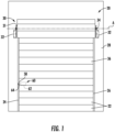
Figure 1 illustrates an interior view of an example vertical door. -
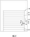
Figure 2 illustrates an exterior view of the example vertical door ofFigure 1 . -
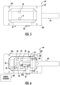
Figure 3 is a front view of an example bolt assembly with an example bolt in a retracted position. -
Figure 4 is a side view of the example bolt assembly ofFigure 3 . -
Figure 5 is another front view of the example bolt assembly ofFigure 3 with the example bolt in an extended position. -
Figure 6 is a cross-sectional view taken along line 6-6 ofFigure 4 . -
Figure 7A is a cross-section view taken along line 7-7 ofFigure 6 of a portion of the example bolt and an example actuator lock assembly in a retracted or non-locking position. -
Figure 7B is a cross-section view of the portion of the bolt and the example actuator lock assembly ofFigure 7A in an extended or locking position. -
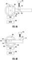
Figure 8A is a cross-section view of another example actuator lock assembly in a locking position. -
Figure 8B is a cross-section view of the example actuator lock assembly ofFigure 8A in a non-locking position. -
Figure 9A is a cross-section view of yet another example actuator lock assembly in a non-locking position. -
Figure 9B is a cross-section view of the actuator lock assembly ofFigure 9A in a locking position. -
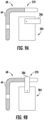
Figure 10 illustrates an example set of slats for the example vertical door. -
Figure 11 illustrates a side view of the example bolt assembly on the example set of slats ofFigure 10 . -
Figure 12 illustrates another example set of slats for the example vertical door. -
Figure 13 illustrates a side view of the example bolt assembly on the example set of slats ofFigure 12 . -
Figure 14 is a front view of an example door spacer. -
Figure 15 is a perspective view of the example door spacer ofFigure 14 . -
Figures 1 and2 illustrate an examplevertical door assembly 20, such as a rollup or overhead style door. Thevertical door assembly 20 includes a plurality ofslats 22 that are rotatably connected to each other along their length and slideably connected to a firstvertical guide rail 24 and a secondvertical guide rail 26 along respective opposite ends of theslats 22. In the illustrated example, thevertical door assembly 20 is used to selectively enclose an opening in awall 28 and secure the opening in the wall through the use of abolt assembly 60. The plurality ofslats 22 include an interior surface 36 (Figure 1 ) that faces towards an enclosed space and an exterior surface 38 (Figure 2 ) that faces away from the enclosed space. Thewall 28 could be a wall locating a building, a shipping container, a trailer, or any other type of arrangement where it is desirable to selectively enclose an opening in a structure. - The
vertical door assembly 20 includes a tension wheel assembly 30 having adrum 31 supported by anaxle 34 to allow the plurality ofslats 22 to move through the first andsecond guide rails slats 22 to roll around theaxle 34 about an axis of rotation A to store the plurality ofslats 22 above the opening in thewall 28. Additionally, the tension wheel assembly 30 could be spring loaded to reduce the force needed to raise the plurality ofslats 22. In the illustrated example, theaxle 34 is supported relative to thewall 28 through abracket 32 located adjacent opposite ends of theaxle 34 and fixed relative to thewall 28. -
Figures 3-5 illustrate an enlarged view of anexample bolt assembly 60. In the illustrated example, thebolt assembly 60 includes abolt housing 62 formed from a front orfirst portion 62A and a back orsecond portion 62B that both at least partially define an interior cavity 63 (Figure 6 ) within thebolt assembly 60. Theback portion 62B includes a back surface that is at least partially in engagement with theexterior surface 38 one of theslats 22 as shown inFigure 2 . Thefront portion 62A also includes afront flange 72A that at least partially engages aback flange 72B on theback portion 62B. The front andback flanges cavity 63 and each includecorresponding fastener openings back portions Figures 3-6 ). - The
bolt assembly 60 also includes abolt 64, which is slidable relative to thebolt housing 62 to allow thebolt 64 to engage an aperture 58 (Figure 1 )in the firstvertical guide rail 24 to prevent the plurality ofslats 22 from moving relative to the first and secondvertical guide rails bolt 64 includes abolt handle 66 that allows a user to manually move thebolt 64 horizontally into and out of theaperture 58 in the firstvertical guide rail 24. Thehandle 66 also extends from thebolt 64 in thecavity 63 through ahandle aperture 67 at least partially defined between thefront flange 72A and theback flange 72B. - The
handle 66 can also include an area of reducedwidth 69A and at least oneindentation 69B, such as a groove or perforation, in the area of attachment of thehandle 66 to thebolt 64. In the illustrated example, the area of reducedwidth 69A includes a pair of recesses that reduce a width of thehandle 66 and the at least oneindentation 69B provides a region of reduced material thickness in thehandle 66. The at least oneindentation 69B can extend across a width of thehandle 66 between the recesses forming the area of reducedwidth 69A or only extend a portion of the width. Theindentation 69B may also include a series of linear perforations or a single perforation in thehandle 66. Thehandle 66 can also be attached to the bolt with a screw 71 designed to fail if an excessive force is applied to thehandle 66. - The combination of the area of reduced
width 69A and the at least oneindentation 69B limits the amount of force that can be applied to thehandle 66 before thehandle 66 separates from thebolt 64. The ability to separate thehandle 66 from thebolt 64 can prevent thebolt 64 from being forced open by applying a large force to thehandle 66. Additionally, the location of separation between thehandle 66 and thebolt 64 is located within thebolt housing 62 to prevent any remaining portion of thehandle 66 to be used to force thebolt 64 to an open position. If thehandle 66 separates from thebolt 64, thebolt assembly 60 can be serviced by installing anew bolt 64 and handle 66 instead of replacing the entire assembly. - Furthermore, this disclosure also applies to the
bolt assembly 60 being located adjacent the secondvertical guide rail 26. Additionally, theaperture 58 could be located separate from one of the first or secondvertical guide rails wall 28 or another structure that is fixed relative to thewall 28. - The
bolt assembly 60 includes anelectronic control module 40 in electrical communication with anactuator lock assembly 84 to selectively secure thebolt 64 when in a locking position or release thebolt 64 when in a non-locking position as will be described further below. In the illustrated example, theelectronic control module 40 includes a printed circuit board in communication withmemory 42, aprocessor 44, awireless communications device 46, and at least oneindicator light 48. Thememory 42 is preprogrammed and in communication with theprocessor 44, such as a controller, to perform the operations described below. - In one example, the
wireless communications device 46 is capable of forming a Wi-Fi or Bluetooth connection to transfer a desired locked or unlocked request from a user wirelessly to thewireless communications device 46 to change an operating state of theactuator lock assembly 84 and thebolt 64. Theelectronic control module 40 may also utilize the at least oneindicator light 48 to display a connection status with the user formed with thewireless communications device 46 and/or a locked status of thebolt 64 relative to thebolt housing 62. Theelectronic control module 40 is in electrical communication with abattery 50 or apower input port 51 to provide power to theelectronic control module 40. - In the illustrated example, the
actuator lock assembly 84 includes an actuator with a retention feature, such as aretractable pin 86, that is accepted within anaperture 70 in thebolt 64. Alternatively, theactuator lock assembly 84 could include more than oneretractable pin 86 and more than oneaperture 70 such that each of theretractable pins 86 is accepted within a corresponding one of theapertures 70. Theaperture 70 is located on aprotrusion 68 on thebolt 64. When theelectronic control module 40 sends an electrical signal to theactuator lock assembly 84 that corresponds to the locking position, theretractable pin 86 extends outward into theaperture 70 as shown inFigure 7B . However, before theretractable pin 86 can engage theaperture 70 in thebolt 64, thebolt 64 must be manually moved into theaperture 58 to prevent the plurality ofslats 22 from moving vertically. When theelectronic control module 40 sends an electrical signal to theactuator lock assembly 84 that corresponds to a non-locking position, theretractable pin 86 retracts inward so that theretractable pin 86 is not in engagement with theaperture 70 or thebolt 64. - During operation of the
bolt assembly 60, a user communicates with theelectronic control module 40 through thewireless communications device 46. The communication between the user and thewireless communications device 46 may occur through an application or web interface on a user's mobile device through a Bluetooth or other type of wireless connection. Theelectronic control module 40 can then send an electrical signal to theactuator lock assembly 84 to move theretractable pin 86 to one of the locking position (Figure 7B ) or the non-locking position (Figure 7A ) depending on the input from the user. - Alternatively, the retention feature could include a
rotatable lock 186 with abolt passageway 187 that extends through a center portion of therotatable lock 186 and between opposite edges of therotatable lock 186. Therotatable lock 186 is driven by amotor 188 that turns agear 190 that engagesteeth 192 that surround therotatable lock 186 to move therotatable lock 186 between an unlocked position (Figure 8A ) and a locked position (Figure 8B ). In one example, thegear 190 is a worm gear and theteeth 192 form a worm wheel and in another example, thegear 190 is a pinion gear and theteeth 192 form a ring gear. - When in the unlocked position, a
protrusion 170 on thebolt 64 is able to slidebly move through thepassageway 187 in the rotatable lock. In order to move thebolt 64 to a locked position, thebolt 64 is slide out of thebolt passageway 187 and theelectronic control module 40 sends a signal to themotor 188 to drive thegear 190. Thegear 190 then rotates therotatable lock 186 such that an end of theprojection 170 is aligned with abody portion 189 of therotatable lock 186. Additionally, adetented lock 192 could be moved into anaperture 196 in theprojection 170 by anactuator 194 in communication with theelectronic control module 40 when in the locked position ofFigure 8A to further secure thebolt 64. - Furthermore, the retention feature could include a
rotatable lock 286 that is rotatable into an aperture 270 (Figure 9B ) and out of the aperture 270 (Figure 9B ) in response to electrical signals received by anactuator lock assembly 284. - Additionally, the
electronic control module 40 can store a record of the user that accessed thewireless communications device 46 on thememory 42 on theelectronic control module 40. The record can include the identity of the user based on the device used to access thewireless communications device 46 and the time of the request. Alternatively, theelectronic control module 40 can send the record to a remote location 80 (Figure 6 ) through use of thewireless communications device 46 to monitor access through thevertical door assembly 20. Additionally, theremote location 80 can send a signal to theelectronic control module 40 through thewireless communications device 46 to direct theactuator lock assembly 84 to move between one of the locking position and non-locking position. -
Figures 10 and 11 illustrate thebolt assembly 60 attached to a plurality ofslats 22A. In the illustrated example, the plurality ofslats 22A include fourfastener openings 75A that correspond to thefastener openings bolt assembly 60. When theback portion 62B is located within a recessed portion of theslats 22, an upper and lower portion of theback flange 72B sits flush against and in directed contact with the portion of theslats 22A having thefastener openings 75A.Fasteners 77 can then secure thebolt assembly 60 to theslats 22A and extend through abacker plate 88A in contact with aninterior surface 36A of theslats 22A. One feature of thebacker plate 88A is to provide an engagement surface for thefasteners 77 that distributes the load of thefasteners 77 over a larger area of theslats 22 to prevent thefasteners 77 from pulling through theslats 22A and separating thebolt assembly 60 from thevertical door assembly 20. - Alternatively, as shown in
Figures 12-15 , when thebolt assembly 60 is used with a plurality ofslats 22B having a two-hole configuration with a pair ofspacers 90 to position thebolt assembly 60 relative to theslats 22B. Thespacers 90 includes a boltassembly contact side 91 and aslat contact side 92 opposite the boltassembly contact side 91. The boltassembly contact side 91 includes a surface that contacts both a portion ofback flange 72B and a central region of theback portion 62B that fits within a recessed area of theslats 22B. Theslat contact side 92 includes a surface that contacts theslat 22B and anend wall 93 at each opposing end of afirst wall 96 and asecond wall 97. Theend walls 93 and the first andsecond walls cavity 94 with theslats 22B. Thefirst wall 96 includes alip 98 along an outer edge that extends between theend walls 93 that directly contacts theslats 22B. Thespacer 90 also includesfastener openings 95 that acceptfasteners 77 extending throughfastener openings bolt assembly 60. Therefore, thefasteners 77 secure thebolt assembly 60 to thespacers 90 and not theslats 22B. -
Fasteners 79 secure thebolt assembly 60 to theslats 22B by extending through theback portion 62B of thebolt assembly 60 into abacker plate 88B in contact with aninterior surface 36B of theslats 22B. One feature of thebacker plate 88B is to provide an engagement surface for thefasteners 79 that distributes the load of thefasteners 79 over a larger area of theslats 22B to prevent thefasteners 79 from pulling through theslats 22B and separating thebolt assembly 60 from thevertical door assembly 20. - Although the different non-limiting examples are illustrated as having specific components, the examples of this disclosure are not limited to those particular combinations. It is possible to use some of the components or features from any of the non-limiting examples in combination with features or components from any of the other non-limiting examples.
- It should be understood that like reference numerals identify corresponding or similar elements throughout the several drawings. It should also be understood that although a particular component arrangement is disclosed and illustrated in these exemplary embodiments, other arrangements could also benefit from the teachings of this disclosure.
- The foregoing description shall be interpreted as illustrative and not in any limiting sense. A worker of ordinary skill in the art would understand that certain modifications could come within the scope of this disclosure.
- Aspects and embodiments of the present invention include those set out in the following numbered clauses:
- 1. A vertical door latch assembly comprising:
- a housing;
- a bolt movably attached to the housing and including a catch portion;
- an actuator lock assembly located within the housing for securing the bolt between a locking position preventing movement of the bolt and a non-locking position allowing movement of the bolt; and
- a controller in electrical communication with the actuator lock assembly and configured to direct the actuator lock assembly between the locking position and the non-locking position.
- 2. The assembly of clause 1, further comprising at least one of a battery and an input power port in electrical communication with the controller and the actuator lock assembly.
- 3. The assembly of clause 1, further comprising at least one spacer having a housing engaging surface and a door engaging surface.
- 4. The assembly of clause 1, wherein the actuator lock assembly includes an actuator configured to move at least one retention feature between the locking position and the non-locking position.
- 5. The assembly of clause 4, wherein the retention feature includes at least one retractable pin or at least rotatable projection.
- 6. The assembly of clause 1, wherein the housing includes a first portion and a second portion that at least partially define a cavity for supporting the controller and the actuator lock assembly.
- 7. The assembly of
clause 6, wherein the second portion includes a door contact surface on an opposite side of the second portion from an inner cavity defining surface. - 8. The assembly of
clause 6, wherein the first portion includes an outer flange that surrounds the cavity and the second portion includes an inner flange that surrounds the cavity. - 9. The assembly of clause 8, wherein the inner flange includes at least one inner flange fastener opening and the outer flange includes at least one outer flange fastener opening aligned with the inner flange fastener opening.
- 10. The assembly of clause 8, wherein the bolt includes a handle extending from the cavity and through a handle opening between the inner flange and the outer flange.
- 11. The assembly of clause 10, wherein the bolt includes a distal end for engaging an aperture in a static structure with the handle fixed relative the distal end of the bolt and the handle includes at least one of an area of reduced width or an indentation at least partially spanning a width of the handle.
- 12. The assembly of clause 1, wherein the controller is in electrical communication with a wireless communications device.
- 13. The assembly of clause 12, wherein the wireless communications device includes at least one of a Bluetooth communicator of a Wi-Fi communicator.
- 14. A method of operating a vertical door latch assembly comprising the steps of:
- receiving a wireless signal from a user on an electronic control module corresponding to one of a locking position in locking engagement with a bolt or a non-locking position in non-locking engagement with the bolt; and
- sending a signal from the electronic control module to an actuator lock assembly to move the actuator lock assembly to the one of the locking position or the non-locking position.
- 15. The method of clause 14, further comprising storing a record of receiving the wireless signal from the user on memory in the electronic control module.
- 16. The method of clause 15, further comprising transmitting the record to a remote location.
- 17. The method of clause 14, wherein the electronic control module is located in a cavity at least partially defined by a housing and the housing includes a first portion having an outer flange and a second portion having an inner flange and the inner flange and the outer flange are in at least partial contact.
- 18. The method of clause 14, wherein the actuator lock assembly includes an actuator configured to move at least one retention feature between the locking position and the non-locking position.
- 19. The method of clause 18, wherein the retention feature includes at least one retractable pin that is at least partially located in a corresponding aperture in the bolt when in the locking position and the at least one retractable pin is spaced from the corresponding aperture in the bolt when in the non-locking position.
- 20. The method of clause 19, wherein the retention feature includes at least one rotatable projection that is at least partially located in a corresponding aperture in the bolt when in the locking position and the at least one rotatable projection is spaced from the corresponding aperture in the bolt when in the non-locking position.
- The scope of the invention is defined in the following claims:
Claims (15)
- A vertical door latch assembly comprising:a housing defining an internal cavity;an actuator lock assembly including an actuator with a retention feature positioned within the internal cavity that is moveable between a lock position and an unlock position;a lock body having an aperture that receives at least a portion of the retention feature when in the lock position;wherein the actuator is coupled to the retention feature and moves the retention feature along a first path between at leasta first position wherein the retention feature is received within the aperture, anda second position wherein the retention feature moves out of the aperture; andwherein, once the retention feature moves out of the aperture, the lock body is moveable along a second path that is different from the first path; anda controller in electrical communication with the actuator lock assembly and configured to direct the actuator lock assembly between the lock position and the unlock position.
- The vertical door latch assembly of claim 1, wherein the housing includes a first portion and a second portion that at least partially define the internal cavity, and wherein the first portion includes a first flange that extends at least partially around the internal cavity, and wherein the second portion includes a second flange that extends at least partially around the internal cavity, and, wherein the internal cavity supports the controller and the actuator lock assembly.
- The vertical door latch assembly of claim 1, wherein the actuator comprises a motor.
- The vertical door latch assembly of claim 3, wherein the actuator further comprises a rotating member driven by the motor.
- The vertical door latch assembly of claim 4, wherein the rotating member comprises a gear.
- The vertical door latch assembly of claim 3, wherein the retention feature comprises a retractable pin.
- The vertical door latch assembly of claim 1, wherein the lock body comprises a bolt.
- The vertical door latch assembly of claim 1, wherein the actuator comprises a detented lock.
- The vertical door latch assembly of claim 8, wherein the actuator lock assembly further includes a motor driving a gear to rotate a rotatable lock with an inner passageway that extends through a center portion of the rotatable lock.
- The vertical door latch assembly of claim 9, wherein the rotatable lock is rotated between at least a first position where the inner passageway aligns with a protrusion of the lock body and a second position where the inner passageway is not aligned with a protrusion of the lock body.
- The vertical door latch assembly of claim 1, wherein the retention feature comprises a rotatable lock that is rotatable into the aperture to provide the lock position and is rotated out of the aperture to provide the unlock position.
- The vertical door latch assembly of claim 1, wherein the second path is non-parallel with the first path.
- The vertical door latch assembly of claim 1, wherein the lock body includes an arm portion protrusion with the aperture that aligns with the retention feature to receive the retention feature when in the lock position.
- The vertical door latch assembly of claim 1, wherein the housing comprises a cover portion and a back portion that are secured together to provide the internal cavity that receives the lock body, and wherein a rear surface of the housing is mounted to a door surface comprised of a plurality of slats.
- The vertical door latch assembly of claim 14, wherein one end of the lock body is engageable with an aperture in a vertical guide rail that extends along one side of the plurality of slats.
Applications Claiming Priority (3)
| Application Number | Priority Date | Filing Date | Title |
|---|---|---|---|
| US201962890233P | 2019-08-22 | 2019-08-22 | |
| PCT/US2020/047401 WO2021035140A1 (en) | 2019-08-22 | 2020-08-21 | Latch assembly for vertical door |
| EP20765434.4A EP4018059B1 (en) | 2019-08-22 | 2020-08-21 | Latch assembly for vertical door |
Related Parent Applications (2)
| Application Number | Title | Priority Date | Filing Date |
|---|---|---|---|
| EP20765434.4A Division-Into EP4018059B1 (en) | 2019-08-22 | 2020-08-21 | Latch assembly for vertical door |
| EP20765434.4A Division EP4018059B1 (en) | 2019-08-22 | 2020-08-21 | Latch assembly for vertical door |
Publications (2)
| Publication Number | Publication Date |
|---|---|
| EP4290035A2 true EP4290035A2 (en) | 2023-12-13 |
| EP4290035A3 EP4290035A3 (en) | 2024-04-03 |
Family
ID=72340442
Family Applications (2)
| Application Number | Title | Priority Date | Filing Date |
|---|---|---|---|
| EP23202840.7A Pending EP4290035A3 (en) | 2019-08-22 | 2020-08-21 | Latch assembly for vertical door |
| EP20765434.4A Active EP4018059B1 (en) | 2019-08-22 | 2020-08-21 | Latch assembly for vertical door |
Family Applications After (1)
| Application Number | Title | Priority Date | Filing Date |
|---|---|---|---|
| EP20765434.4A Active EP4018059B1 (en) | 2019-08-22 | 2020-08-21 | Latch assembly for vertical door |
Country Status (3)
| Country | Link |
|---|---|
| US (6) | US11859410B2 (en) |
| EP (2) | EP4290035A3 (en) |
| WO (1) | WO2021035140A1 (en) |
Families Citing this family (12)
| Publication number | Priority date | Publication date | Assignee | Title |
|---|---|---|---|---|
| US10657795B1 (en) | 2019-02-01 | 2020-05-19 | SimpliSafe, Inc. | Alarm system with first responder code for building access |
| US11170597B2 (en) * | 2019-07-15 | 2021-11-09 | Integrated Solutions, Inc. | Intelligent integrated locking devices and systems |
| US11933092B2 (en) | 2019-08-13 | 2024-03-19 | SimpliSafe, Inc. | Mounting assembly for door lock |
| US11859410B2 (en) * | 2019-08-22 | 2024-01-02 | Carrier Corporation | Latch assembly for vertical door |
| US20210209924A1 (en) * | 2020-01-06 | 2021-07-08 | Synergy Product Solutions Inc. | Overhead door monitor and sensor apparatus |
| US12385289B2 (en) * | 2022-03-08 | 2025-08-12 | Opentech Alliance, Inc. | Multi-unit access control and information management system |
| USD993743S1 (en) * | 2022-09-20 | 2023-08-01 | Bing Zhou | Window lock |
| WO2024073300A1 (en) * | 2022-09-27 | 2024-04-04 | Assa Abloy Americas Residential Inc. | Electronic lockset for sliding door |
| WO2024097107A1 (en) * | 2022-11-01 | 2024-05-10 | Janus International Group, Llc | Door lock and process for installing door lock |
| SE546433C2 (en) * | 2023-03-07 | 2024-11-05 | Assa Abloy Global Solutions Ab | Latch assembly with an elongated latch slider and an electromechanical lock device, and access member system |
| CN119283706B (en) * | 2023-12-29 | 2025-11-21 | 奥动新能源股份有限公司 | Level changing table |
| US12560004B2 (en) * | 2024-02-04 | 2026-02-24 | Foshan Wangya Intelligent Technology Co., Ltd. | Full-automatic single bolt lock body with a built-in motor |
Family Cites Families (100)
| Publication number | Priority date | Publication date | Assignee | Title |
|---|---|---|---|---|
| US49297A (en) | 1865-08-08 | Improvement in locks | ||
| US1024036A (en) * | 1910-01-06 | 1912-04-23 | Ware Machine & Loom Company | Picker-check. |
| US1164743A (en) | 1915-07-08 | 1915-12-21 | William H Musselman | Lock. |
| US2045186A (en) * | 1933-09-26 | 1936-06-23 | Honsel Fritz | Combined electrical and key operated lock |
| US2276740A (en) | 1939-12-23 | 1942-03-17 | Gen Electric | Control device |
| US2660632A (en) * | 1951-12-14 | 1953-11-24 | Makishima Kenji | Burglar alarm safety lock |
| US3425742A (en) | 1967-08-08 | 1969-02-04 | Benjamin Thomas Rauber Jr | Locking means for locking the top of a convertible automobile |
| US3795417A (en) | 1971-10-18 | 1974-03-05 | D Cohen | Electrically operated coin box lock |
| US3933382A (en) * | 1973-07-13 | 1976-01-20 | Transport Security Systems, Inc. | Security lock |
| US3926019A (en) | 1974-03-15 | 1975-12-16 | Eugene H Clement Hi Gene Laund | Locking system |
| US4021065A (en) * | 1975-07-08 | 1977-05-03 | Geringer Arthur V | Electric lock |
| US4233595A (en) * | 1978-11-30 | 1980-11-11 | Christoph Emmerich Kg | Chain-type door latch and alarm |
| US4254582A (en) * | 1979-07-25 | 1981-03-10 | Mcgee Michael H | Electrically actuated overhead garage door opener assembly |
| JPS6016198Y2 (en) | 1980-01-31 | 1985-05-20 | 国産金属工業株式会社 | door handle lock |
| US4667994A (en) * | 1986-02-06 | 1987-05-26 | Best Lock Corporation | Frangible spindle |
| FR2594877B1 (en) * | 1986-02-24 | 1991-06-21 | Fichet Bauche | DEVICE FOR LOCKING AND UNLOCKING ANY BODY, SUCH AS FOR EXAMPLE A BAR HAVING PENES |
| DE3618251A1 (en) | 1986-05-30 | 1987-12-03 | Dieter Schmermbeck | METHOD AND VOLCANIZING SLEEVE FOR REPAIRING AND RENEWING VEHICLE TIRES |
| DE3720550A1 (en) | 1987-06-22 | 1989-01-05 | Zeiss Ikon Ag | Multiple-locking device |
| US5044182A (en) | 1988-09-26 | 1991-09-03 | Totten Clyde D | Automatic deadbolt |
| US5049727A (en) | 1988-12-28 | 1991-09-17 | Pitney Bowes Inc. | Locking device for removable postage meter |
| US5533561A (en) * | 1992-05-24 | 1996-07-09 | Forehand, Iv; L. Langstroth | Garage door security system |
| EP0582742B1 (en) * | 1992-08-13 | 1996-04-17 | Kaba Schliesssysteme Ag | Locking device for a reinforced door |
| US5474348A (en) | 1993-08-24 | 1995-12-12 | Best Lock Corporation | Motorized actuator for mortise lockset |
| DE19628994A1 (en) * | 1996-07-18 | 1998-01-22 | Mauer Gmbh | Electromagnetically operated lock |
| CN1156837C (en) | 1998-10-05 | 2004-07-07 | 蒂雅克株式会社 | Data conversion device with safety circuit |
| US6580355B1 (en) * | 1999-06-11 | 2003-06-17 | T.K.M. Unlimited, Inc. | Remote door entry system |
| DE20100847U1 (en) * | 2001-01-16 | 2001-04-19 | Huang, Tsun Thin, Taipeh / T'ai-pei | Chip-operated electronic lock |
| DE10208451A1 (en) * | 2002-02-27 | 2003-09-04 | Bremicker Soehne Kg A | Window / door lock |
| US6644072B1 (en) * | 2002-07-01 | 2003-11-11 | Hui-Hua Hsieh | Remote-controlled door lock |
| US6845641B2 (en) * | 2002-08-02 | 2005-01-25 | Hui-Hua Hsieh | Remote-controlled door lock |
| US6813916B2 (en) * | 2002-11-12 | 2004-11-09 | Ching-Wen Chang | Remote control lock structure |
| US7059159B2 (en) | 2003-02-06 | 2006-06-13 | Mi-Jack Products, Inc. | Security system for cargo trailers |
| US7040675B1 (en) | 2003-02-12 | 2006-05-09 | The Eastern Company | Linkage operated latching system |
| US7484391B1 (en) | 2003-09-24 | 2009-02-03 | Moore Gregory B | Door lock system for trailers and cargo containers |
| GB0325682D0 (en) | 2003-11-04 | 2003-12-10 | Nicholas Paul | A sheilded lock |
| US7240524B1 (en) | 2004-06-15 | 2007-07-10 | White Bryan A | Locking apparatus for a garage door |
| US8596330B2 (en) | 2004-12-03 | 2013-12-03 | Sargent Manufacturing Company | Low cost garage door lock |
| US7698917B2 (en) | 2006-03-06 | 2010-04-20 | Handytrac Systems, Llc | Electronic deadbolt lock with a leverage handle |
| DE202006017308U1 (en) * | 2006-11-10 | 2008-03-13 | Arca Beteiligungen Gmbh | Retrofittable actuator drive for a swing door or the like. |
| US7350383B1 (en) * | 2006-11-13 | 2008-04-01 | Ching-Hung Kuo | Electronic lock |
| US20090260407A1 (en) | 2006-12-04 | 2009-10-22 | Rodney Henson | Locking assembly |
| ATE549478T1 (en) * | 2007-03-23 | 2012-03-15 | Feig Electronic Gmbh | MONITORING METHOD FOR A MOTOR DRIVEN GATE |
| US7823993B2 (en) | 2007-04-03 | 2010-11-02 | Carefusion 303, Inc. | Piezo actuated slide latching mechanism |
| US8403376B2 (en) * | 2007-06-12 | 2013-03-26 | Compx International Inc. | Convertible motorized latch |
| US20090206985A1 (en) | 2008-02-19 | 2009-08-20 | Advanced Connection Technology Inc. | Control method and system for controlling access through an automated door |
| DE102009041101A1 (en) * | 2009-09-14 | 2011-03-24 | K.A. Schmersal Holding Gmbh & Co. Kg | Guard for a component for closing an opening |
| KR101072579B1 (en) | 2009-11-05 | 2011-10-11 | 주식회사 삼코 | Door cover locking apparatus of washer |
| CA2794571C (en) | 2010-04-07 | 2017-08-15 | Sargent And Greenleaf, Inc. | Shock resistant lock |
| US8276948B2 (en) | 2010-05-24 | 2012-10-02 | Adams Rite Manufacturing Co. | Multiple access door lock mechanism with reversible cam actuation |
| FR2963043B1 (en) | 2010-07-26 | 2012-07-27 | Cogelec | ELECTRONIC LOCK |
| EP2663706B1 (en) * | 2011-01-10 | 2025-01-01 | Ingersoll Rand Company | Door assembly and method of determining the cause of an acceleration at a door |
| US8789859B2 (en) | 2011-04-14 | 2014-07-29 | Janus International Group, Llc | Electronic lock for a rollup door |
| US8495899B2 (en) * | 2011-05-23 | 2013-07-30 | Klaus W. Gartner | Electromechanical lock |
| US20130038183A1 (en) | 2011-08-12 | 2013-02-14 | Inno Digic Limited | Driving Machine with Detachable Battery for Electric Garage Doors and Electric Rolling Doors |
| US9151084B2 (en) | 2011-08-15 | 2015-10-06 | Cold Chain, Llc | Insulated overhead door |
| US9187931B2 (en) | 2011-09-01 | 2015-11-17 | Jamas Enterprises LLC | Sliding pin lock mechanism for overhead door |
| GB201115303D0 (en) | 2011-09-05 | 2011-10-19 | Pegasus Innovation Ltd | Fastening device |
| WO2013063642A1 (en) | 2011-10-31 | 2013-05-10 | Automatic Technology (Australia) Pty Ltd | Safety system for moveable closures |
| TWM445054U (en) | 2012-05-02 | 2013-01-11 | Celestica Int Inc | Lock and the electronic device and computer casing utlizing the lock |
| US10465422B2 (en) * | 2012-05-10 | 2019-11-05 | 2603701 Ontario Inc. | Electronic lock mechanism |
| FR2994997B1 (en) | 2012-09-04 | 2014-08-29 | Moving Magnet Tech | MOTORIZED LOCKING DEVICE RESISTANT TO SHOCKS |
| US9353550B1 (en) | 2012-09-13 | 2016-05-31 | Shelby G. Smith, III | Lock engagement status indicator system |
| US9355511B2 (en) | 2013-02-07 | 2016-05-31 | Schlage Lock Company Llc | Apparatuses and methods for displaying feedback indicators via a keypad |
| US10214947B2 (en) | 2013-02-28 | 2019-02-26 | Otto Llc | Door lock assembly for a dwelling |
| US9384655B2 (en) * | 2013-03-15 | 2016-07-05 | Vivint, Inc. | Detecting destruction of an automation system component |
| US9704314B2 (en) | 2014-08-13 | 2017-07-11 | August Home, Inc. | BLE/WiFi bridge that detects signal strength of Bluetooth LE devices at an exterior of a dwelling |
| US10062231B2 (en) | 2013-06-10 | 2018-08-28 | Smart Armor Protected, LLC | Wireless method and apparatus for remote lock operating with mobile communication device |
| GB2516950B (en) * | 2013-08-08 | 2020-04-08 | Securefast Plc | Door lock |
| DE102014112319A1 (en) | 2014-08-27 | 2016-03-03 | Mitteldeutsche Tresorbau Gmbh | Compact operating unit for a safe lock |
| US9850685B2 (en) | 2014-09-03 | 2017-12-26 | Schlage Lock Company Llc | Lock drive assemblies |
| US9551167B2 (en) | 2014-09-18 | 2017-01-24 | Mark A. Pickard | Padlock retaining device |
| ES2923690T3 (en) | 2014-12-02 | 2022-09-29 | Carrier Corp | Access control system with transfer of automatic mobile accreditation service |
| US9874045B2 (en) | 2014-12-04 | 2018-01-23 | Larry Buchanan | Door locking system |
| WO2016093873A1 (en) | 2014-12-09 | 2016-06-16 | Kirsen Technologies, Llc | Transportation security system and associated methods |
| US10246904B1 (en) | 2016-02-16 | 2019-04-02 | Bryan White | Garage door locking apparatus |
| GB2561800B (en) | 2016-02-16 | 2021-08-04 | Southco | Electromechanical locking latch |
| AU2016273920B2 (en) * | 2016-05-16 | 2023-02-09 | Automatic Technology (Australia) Pty Ltd | A system for a lock for a closure, a lock for use with such a system, and a closure system |
| DE102016008317B4 (en) | 2016-07-07 | 2018-10-31 | Emz-Hanauer Gmbh & Co. Kgaa | Door lock for a household electrical appliance |
| US10062233B1 (en) | 2016-07-20 | 2018-08-28 | Alarm.Com Incorporated | Automatic emergency door unlock system |
| CN106088849B (en) * | 2016-08-18 | 2018-05-22 | 东莞市锁之道科技有限公司 | A turn cam lock |
| US11028912B2 (en) * | 2016-09-07 | 2021-06-08 | Kiekert Ag | Drive arrangement for motorized adjustment of an actuating element rotatably mounted in a motor vehicle door latch housing |
| CN106246003B (en) | 2016-09-20 | 2018-11-27 | 东莞市锁之道科技有限公司 | Electric mechanism for locking device |
| CA2984993C (en) | 2016-11-10 | 2023-08-22 | Edmond Rampen | Locking device |
| US11808056B2 (en) * | 2017-04-18 | 2023-11-07 | ASSA ABLOY Residential Group, Inc. | Door lock detection systems and methods |
| US10089801B1 (en) | 2017-05-15 | 2018-10-02 | Amazon Technologies, Inc. | Universal access control device |
| US10121301B1 (en) | 2017-06-20 | 2018-11-06 | Amazon Technologies, Inc. | Web-based structure access |
| CN111247301B (en) * | 2017-08-30 | 2021-08-27 | 雅固拉国际有限公司 | Electronic lock for sliding door of cabinet |
| WO2019141471A1 (en) * | 2018-01-22 | 2019-07-25 | Assa Abloy Ab | Determining when a break-in attempt is in process |
| KR101975814B1 (en) | 2018-06-12 | 2019-05-08 | 두얼메카닉스 주식회사 | Door lock device for automatically opening door |
| US10858864B2 (en) | 2018-11-09 | 2020-12-08 | Schlage Lock Company Llc | Motor-driven lock with roller |
| CN109441253A (en) | 2018-12-18 | 2019-03-08 | 厦门汉凌达智能科技有限公司 | A kind of electronic lock for cabinet |
| US11220856B2 (en) * | 2019-04-03 | 2022-01-11 | The Chamberlain Group Llc | Movable barrier operator enhancement device and method |
| AU2020253566B2 (en) * | 2019-04-05 | 2023-07-20 | Dormakaba Usa Inc. | Electronic lock |
| GB2583977B (en) | 2019-05-17 | 2021-05-19 | Kingsway Enterprises Uk Ltd | Door lock |
| US10711489B1 (en) | 2019-05-30 | 2020-07-14 | Digilock Asia Ltd. | Electromechanical multi-directional lock |
| US10914098B2 (en) | 2019-05-30 | 2021-02-09 | Digilock Asia Ltd. | Enclosure latch system |
| US11859410B2 (en) * | 2019-08-22 | 2024-01-02 | Carrier Corporation | Latch assembly for vertical door |
| US11505967B2 (en) | 2019-08-22 | 2022-11-22 | Janus International Group, Llc | Controllable door lock |
| ES2956838T3 (en) * | 2020-05-08 | 2023-12-29 | Zipplify Ab | A set of latch |
| FR3110925B1 (en) * | 2020-05-29 | 2023-05-26 | Vitesco Technologies | Vehicle opening emergency access device with retention lever and pull wire |
-
2020
- 2020-08-21 US US16/999,715 patent/US11859410B2/en active Active
- 2020-08-21 EP EP23202840.7A patent/EP4290035A3/en active Pending
- 2020-08-21 US US16/999,774 patent/US11846120B2/en active Active
- 2020-08-21 WO PCT/US2020/047401 patent/WO2021035140A1/en not_active Ceased
- 2020-08-21 US US16/999,745 patent/US11946286B2/en active Active
- 2020-08-21 EP EP20765434.4A patent/EP4018059B1/en active Active
-
2023
- 2023-10-11 US US18/378,875 patent/US12392166B2/en active Active
- 2023-11-07 US US18/503,318 patent/US12584330B2/en active Active
-
2024
- 2024-02-14 US US18/441,205 patent/US20240183198A1/en active Pending
Also Published As
| Publication number | Publication date |
|---|---|
| EP4018059B1 (en) | 2023-11-22 |
| US20240035309A1 (en) | 2024-02-01 |
| US20240183198A1 (en) | 2024-06-06 |
| US11946286B2 (en) | 2024-04-02 |
| US12584330B2 (en) | 2026-03-24 |
| US11846120B2 (en) | 2023-12-19 |
| US12392166B2 (en) | 2025-08-19 |
| US20210054659A1 (en) | 2021-02-25 |
| US20210054658A1 (en) | 2021-02-25 |
| EP4018059A1 (en) | 2022-06-29 |
| US20240068275A1 (en) | 2024-02-29 |
| WO2021035140A1 (en) | 2021-02-25 |
| US11859410B2 (en) | 2024-01-02 |
| EP4290035A3 (en) | 2024-04-03 |
| US20210054657A1 (en) | 2021-02-25 |
Similar Documents
| Publication | Publication Date | Title |
|---|---|---|
| EP4018059B1 (en) | Latch assembly for vertical door | |
| US6085825A (en) | Power-driven shutter assembly | |
| TWI632280B (en) | Dual hinged door mechanism | |
| CA3130819C (en) | Electronic lock | |
| EP4171998B1 (en) | Motor vehicle with at least one lifting device integrated in the tailgate | |
| CN105431602A (en) | Cabinet gang lock system for electrically lockable slides | |
| EP4018063B1 (en) | Vertical door latch assembly | |
| CN111056412B (en) | Construction elevator cage door and construction elevator cage | |
| EP2924207A1 (en) | Holder | |
| US20220049524A1 (en) | Vertical door latch assembly | |
| JP2001227223A (en) | Lock device for sliding door | |
| US6173594B1 (en) | Locking apparatus for use in game machine | |
| KR20190058751A (en) | the tool box for truck cargo box | |
| JP3997399B2 (en) | Architectural shutter device | |
| JP4649079B2 (en) | Wing lock device | |
| CN215632303U (en) | Lockset triple-linkage module assembly, equipment door and equipment | |
| KR101617737B1 (en) | Door-lock Apparatus for Washing Machine | |
| CN211380320U (en) | Storage cabinet | |
| JPH076309B2 (en) | Shutter locking device | |
| JPH063100Y2 (en) | Shutter lock device | |
| JP2000337062A (en) | Shutter | |
| CN120941455A (en) | A baggage check-in robot |
Legal Events
| Date | Code | Title | Description |
|---|---|---|---|
| PUAI | Public reference made under article 153(3) epc to a published international application that has entered the european phase |
Free format text: ORIGINAL CODE: 0009012 |
|
| STAA | Information on the status of an ep patent application or granted ep patent |
Free format text: STATUS: THE APPLICATION HAS BEEN PUBLISHED |
|
| AC | Divisional application: reference to earlier application |
Ref document number: 4018059 Country of ref document: EP Kind code of ref document: P |
|
| AK | Designated contracting states |
Kind code of ref document: A2 Designated state(s): AL AT BE BG CH CY CZ DE DK EE ES FI FR GB GR HR HU IE IS IT LI LT LU LV MC MK MT NL NO PL PT RO RS SE SI SK SM TR |
|
| REG | Reference to a national code |
Ref country code: DE Ref legal event code: R079 Free format text: PREVIOUS MAIN CLASS: E05C0001040000 Ipc: E05B0017200000 |
|
| PUAL | Search report despatched |
Free format text: ORIGINAL CODE: 0009013 |
|
| AK | Designated contracting states |
Kind code of ref document: A3 Designated state(s): AL AT BE BG CH CY CZ DE DK EE ES FI FR GB GR HR HU IE IS IT LI LT LU LV MC MK MT NL NO PL PT RO RS SE SI SK SM TR |
|
| RIC1 | Information provided on ipc code assigned before grant |
Ipc: E05C 1/04 20060101ALI20240227BHEP Ipc: E05B 65/00 20060101ALI20240227BHEP Ipc: E05B 47/06 20060101ALI20240227BHEP Ipc: E05B 17/20 20060101AFI20240227BHEP |
|
| STAA | Information on the status of an ep patent application or granted ep patent |
Free format text: STATUS: REQUEST FOR EXAMINATION WAS MADE |
|
| 17P | Request for examination filed |
Effective date: 20241003 |
|
| RBV | Designated contracting states (corrected) |
Designated state(s): AL AT BE BG CH CY CZ DE DK EE ES FI FR GB GR HR HU IE IS IT LI LT LU LV MC MK MT NL NO PL PT RO RS SE SI SK SM TR |
|
| STAA | Information on the status of an ep patent application or granted ep patent |
Free format text: STATUS: EXAMINATION IS IN PROGRESS |
|
| 17Q | First examination report despatched |
Effective date: 20260127 |