EP4289741A1 - Door assembly with standard and accessible operating modes - Google Patents
Door assembly with standard and accessible operating modes Download PDFInfo
- Publication number
- EP4289741A1 EP4289741A1 EP23176847.4A EP23176847A EP4289741A1 EP 4289741 A1 EP4289741 A1 EP 4289741A1 EP 23176847 A EP23176847 A EP 23176847A EP 4289741 A1 EP4289741 A1 EP 4289741A1
- Authority
- EP
- European Patent Office
- Prior art keywords
- door
- partition wall
- door assembly
- operating mode
- opening
- Prior art date
- Legal status (The legal status is an assumption and is not a legal conclusion. Google has not performed a legal analysis and makes no representation as to the accuracy of the status listed.)
- Pending
Links
- 238000005192 partition Methods 0.000 claims abstract description 70
- 230000007246 mechanism Effects 0.000 claims abstract description 15
- 208000034819 Mobility Limitation Diseases 0.000 description 4
- 230000008901 benefit Effects 0.000 description 2
- 230000008878 coupling Effects 0.000 description 2
- 238000010168 coupling process Methods 0.000 description 2
- 238000005859 coupling reaction Methods 0.000 description 2
- 230000004308 accommodation Effects 0.000 description 1
- 230000009471 action Effects 0.000 description 1
- 230000000712 assembly Effects 0.000 description 1
- 238000000429 assembly Methods 0.000 description 1
- 238000010276 construction Methods 0.000 description 1
- 238000005096 rolling process Methods 0.000 description 1
- 238000000926 separation method Methods 0.000 description 1
Images


Classifications
-
- B—PERFORMING OPERATIONS; TRANSPORTING
- B64—AIRCRAFT; AVIATION; COSMONAUTICS
- B64D—EQUIPMENT FOR FITTING IN OR TO AIRCRAFT; FLIGHT SUITS; PARACHUTES; ARRANGEMENT OR MOUNTING OF POWER PLANTS OR PROPULSION TRANSMISSIONS IN AIRCRAFT
- B64D11/00—Passenger or crew accommodation; Flight-deck installations not otherwise provided for
- B64D11/06—Arrangements of seats, or adaptations or details specially adapted for aircraft seats
- B64D11/0606—Arrangements of seats, or adaptations or details specially adapted for aircraft seats with privacy shells, screens, separators or the like
-
- E—FIXED CONSTRUCTIONS
- E05—LOCKS; KEYS; WINDOW OR DOOR FITTINGS; SAFES
- E05B—LOCKS; ACCESSORIES THEREFOR; HANDCUFFS
- E05B65/00—Locks or fastenings for special use
- E05B65/08—Locks or fastenings for special use for sliding wings
-
- E—FIXED CONSTRUCTIONS
- E05—LOCKS; KEYS; WINDOW OR DOOR FITTINGS; SAFES
- E05C—BOLTS OR FASTENING DEVICES FOR WINGS, SPECIALLY FOR DOORS OR WINDOWS
- E05C3/00—Fastening devices with bolts moving pivotally or rotatively
- E05C3/004—Fastening devices with bolts moving pivotally or rotatively about an axis perpendicular to the surface on which the fastener is mounted
-
- E—FIXED CONSTRUCTIONS
- E05—LOCKS; KEYS; WINDOW OR DOOR FITTINGS; SAFES
- E05C—BOLTS OR FASTENING DEVICES FOR WINGS, SPECIALLY FOR DOORS OR WINDOWS
- E05C9/00—Arrangements of simultaneously actuated bolts or other securing devices at well-separated positions on the same wing
- E05C9/04—Arrangements of simultaneously actuated bolts or other securing devices at well-separated positions on the same wing with two sliding bars moved in opposite directions when fastening or unfastening
Definitions
- the present disclosure relates generally to door assemblies for use in aircraft and other conveyances, and more particularly to a door assembly providing a first entrance for standard use and a different second entrance for accessible use.
- Aircraft and other passenger conveyances are typically divided into different seating classes.
- Each seating class typically includes features and accommodations commensurate with the fares paid.
- passengers in economy seating classes are typically closely spaced without any physical separation, whereas passengers in premium seating classes may be spaced apart and separated by physical dividers.
- Some premium seating classes include individual passenger suites in which suite access is provided through a dedicated entrance.
- Swinging doors require space within the compartment or aisle to accommodate the length of the door to permit the door to be swung open and closed. Sliding doors require space forward or aft of the doorway to receive the door when open. In aircraft, where space is at a premium and aisle obstructions are to be avoided, swinging doors and sliding doors having a long length are undesirable.
- the inventive concepts of the present disclosure are directed to a door assembly for use in a doorway in an aircraft, other conveyance, or elsewhere.
- the door assembly includes a partition wall configured to move between a first position and a second position, a sliding door including a first door portion and a second door portion, and a latch mechanism operable to couple the first and second door portions.
- a first operating mode of the door assembly the partition wall is maintained in the first position and the sliding door moves to an open state to form a first opening
- a second operating mode of the door assembly the partition wall is moved from the first position to the second position and the sliding door moves to an open state to form a second opening different from the first opening.
- the first opening is not achievable in the second operating mode of the door assembly and the second opening is not achievable in the first operating mode of the door assembly.
- the first operating mode corresponds to standard use and the second operating mode corresponds to accessible use, and wherein the second opening is longitudinally shifted relative to the first opening.
- the first and second openings have a substantially equal width dimension or wherein a width dimension of the second opening is greater than a width dimension of the first opening.
- the first and second door portions uncouple, and the first door portion moves relative the second door portion.
- the first and second door portions are coupled and move together relative to the partition wall.
- the first and second door portions uncouple, and the first door portion moves relative to the second door portion.
- the first and second door portions are coupled and move together relative to the partition wall.
- the latch mechanism includes a rotating lever and a bevel gear configuration.
- the inventive concepts of the present disclosure are directed to a passenger suite including a partition wall defining an interior space, a passenger seat positioned in the interior space, an entrance formed between the partition wall and a spaced structure, and a door assembly.
- the door assembly includes a movable partition wall configured to move between a first position and a second position, a sliding door including a first door portion and a second door portion, and a latch mechanism operable to couple the first and second door portions.
- a first operating mode of the door assembly In use, in a first operating mode of the door assembly the movable partition wall is maintained in the first position and the sliding door moves to an open state to form a first opening, and in a second operating mode of the door assembly the movable partition wall is moved from the first position to the second position and the sliding door moves to an open state to form a second opening different from the first opening.
- Benefits of the embodiments described herein include a door assembly configured to form a first entrance during standard use of the door and a second entrance during accessible use of the door, wherein the second entrance is not merely an expansion of the first entrance.
- the present disclosure provides a door assembly for use in an aircraft, other conveyances, and elsewhere to provide access into a dedicated space, for instance a passenger suite, compartment, lavatory, etc.
- the door assembly is configured to operate in different modes, wherein a first mode corresponds to standard use by passengers without mobility limitations, and the second mode corresponds to accessible use by passengers with mobility limitations, for instance passengers using a wheelchair or other assistance device.
- the majority of use may be standard use whereas the accessible use may be occasional.
- the door assembly forms a first entrance or door opening.
- the door assembly forms a second entrance or door opening different from the first entrance.
- the second entrance is longitudinally shifted as compared to the first entrance, i.e., the second entrance is not present in the first operating mode of the door assembly and the first entrance is not present in the second operating mode of the door assembly. As such, the second entrance is not an extension of the first entrance.
- the door assembly is further configured to form modified versions of the first and second entrances.
- a door assembly according to the present disclosure is shown generally at refence numeral 100.
- the door assembly 100 is shown, for example, utilized with an entrance of a passenger suite 102 in an aircraft.
- the passenger suite 102 may be part of a larger seating arrangement including a plurality of adjacent passenger suites.
- a portion of the passenger seating arrangement includes longitudinally adjacent passenger suites positioned laterally adjacent an aisle, for instance a longitudinal aisle parallel to an aircraft longitudinal axis.
- each suite extends from the longitudinal aisle to the fuselage.
- the door assembly 100 operates to provide access into the suite 102 and closes for privacy.
- the passenger suite 102 includes a passenger seat 104 and at least one passenger amenity positioned in the suite.
- the passenger suite 102 is defined, at least in part, by at least one partition wall 106. As shown, a portion of the partition wall 106 extends along the aisle and a further portion of the partition wall extends behind the passenger seat 104. In some embodiments, like partition walls 106 are repeated along the longitudinal length of the passenger cabin for efficiency and to separate and define individual passenger suites. Further portions of the partition wall 106 may define other spaces within the suite and support mounted structures such as video monitors 108. In some embodiments, the portion of the partition wall 106 extending along the aisle also extends along a portion of the passenger seat 104. As shown, the passenger seat 104 is angled away from the aisle; however, other seat angles are envisioned such as parallel and angled toward the aisle.
- the suite entrance 110 is generally positioned between spaced partition walls, for instance between a first partition wall 106 associated with a first suite and a spaced apart and longitudinally adjacent second partition wall 122 associated with a second suite 124.
- the first partition wall may be associated with the first passenger suite 102 and the second partition wall may be associated with a monument, bulkhead, lavatory, etc. positioned longitudinally adjacent the first passenger suite.
- the suite entrance 110 provides ingress and egress directly from the longitudinal aisle such that each suite may have its own dedicated entrance.
- the door assembly 100 generally includes a sliding door 112 and a moveable partition wall 114 configured to support and interact with the door. As shown, a bottom edge of the door 112 is spaced above the floor 116. In use, the door 112 translates substantially horizontally forward and aft between open and closed conditions of the door. Assuming the passenger seat 104 is oriented forward facing, the door 112 translates horizontally aft to open and translates horizontally forward to close.
- the partition wall 106 may extend from the floor 116 to a predetermined height above the floor, preferably above the height of the passenger seat 104 to enhance privacy for the suite occupant.
- the door assembly 100 generally includes a movable portion of the partition wall 114, the door 112, and a latch mechanism as described further below.
- the door 112 generally includes a first door portion 118 and a second door portion 120, wherein the first and second door portions are configured to be coupled or decoupled depending on the entrance or door opening to be formed.
- FIGS. 1 and 2 show the first and second door portions 118, 120 in a coupled state and fully closed. In the fully closed condition, the second door portion 120 closest the second partition wall 122 may be attached to or positioned proximal the second partition wall, depending on the safety requirements of the door.
- each of the first and second door portions 118, 120 are rigid panels having a unitary or combinatorial construction. In other embodiments, at least one of the panels are flexible for emergency egress.
- the first door portion 118 decouples from the second door portion 120, via a latch mechanism, and translates or otherwise moves apart from the second door portion 120 to form a first entrance or door opening 126.
- the first entrance 126 is formed between the facing edges of the spaced first and second door portions 118, 120.
- the first entrance 126 may be formed between the stationary second door portion 120 and the facing edge of the partition wall 114 when the first door portion 118 fully retracts into the partition wall.
- the first entrance 126 has a first width dimension w that corresponds to a standard entrance for use by passengers without mobility limitations.
- the movable partition wall 114 moves relative to the passenger seat 104 and further apart from the longitudinally adjacent partition wall 122 to form a second entrance 128 for accessible use.
- the second entrance 128 is positioned further aft as compared to the first entrance (126 in FIGS. 3 and 4 ) revealing more of the passenger seat 104 to facilitate lateral transfer.
- the second entrance has a width dimension w' which is larger than the width dimension w. Comparing the second entrance 128 to the first entrance 126, the second entrance is not only larger but is longitudinally shifted relative to the suite 102. As shown, moving the partition wall 114 aft clears additional space alongside the seat 104 for passenger transfer from the aisle, for instance from a wheelchair to the seat.
- the first door 118 may decouple from the second door 120 such that the second door remains attached or in otherwise close proximity to the partition wall 122 of the adjacent suite.
- the first door 118 may stow within the shifted partition wall 114.
- Mechanisms for shifting the movable portion of the partition wall 114 relative to stationary portions of the partition wall 106 may be conventional, such as guide tracks attached to the floor or the stationary partition wall defining engagement surfaces on which sliding or rolling members affixed to the movable partition wall engage.
- the movable partition wall 114 in a modified version of the first operating mode, or as an intermediate mode between the standard and accessible operating modes, the movable partition wall 114 remains stationary and the first and second door portions 118, 120 are coupled and move together. As shown, the movable partition wall 114 defines an interior space for receiving at least the first door portion 118. Alternatively, the coupled first and second door portions 118, 120 may move to a position alongside the movable partition wall 114, for instance to the inside of the partition wall apart from the aisle.
- a different first entrance 130 may be formed between the second door portion 120 and the adjacent partition wall 122.
- the different first entrance has a width w" which may or may not correspond to the width w depending on the amount of aft travel of the doors 118, 120 relative to the movable partition wall 114.
- the modified first entrance corresponds to standard use for passengers without mobility limitations. As shown, when open, a minor portion of the first door portion 118 and the entirety of the second door portion 120 are positioned outside of the movable partition wall 114.
- FIGS. 9 and 10 show yet another modified entrance 132 formed between the movable partition wall 114 and the adjacent partition wall 122.
- the modified entrance 132 defines a width dimension w′′′ which may be greater or equal to at least one of the above widths.
- the entrance 130 corresponds to an accessible operating mode in which the reduced mobility passenger requires greater clearance between the passenger seat 104 and forward partition wall 122 as compared to alongside the passenger seat. As shown, the first door portion is received within the wall as is most of the second door portion 120, thereby expanding the entrance width dimension.
- the movable partition wall 114 may shift aft to form an entrance extending between the spaced partition wall 122 and the facing edge of the shifted partition wall 114.
- the door assembly as described above is reconfigurable to form different entrances depending on different combinations of the movable partition wall position, coupled state of the first and second door portions, and amount of aft travel of the at least one door portion.
- the drawing figures show at least one standard operating mode and at least one accessible operating mode.
- the at least one standard operating mode is achievable by different combinations of coupled and uncoupled states of the first and second door portions and travel relative to the stationary partition wall.
- the at least one accessible operating mode is achievable by different combinations of partition wall movement, door coupling states and door movements.
- the first and second entrances for respective standard and accessible use are different entrances, and not merely one being an extension of the other.
- the first opening may be formed by maintaining the first position of the movable partition wall and opening at least the first door portion.
- the movable partition wall is moved from the first position to the second position and at least the first door portion is moved to the open state.
- the second opening is not an expansion of the first opening but instead is a newly formed opening longitudinally shifted relative to the first opening.
- the first opening may extend from the forward wall to about the forward end of the passenger seat, whereas the second opening may extend from about the side of the passenger seat to about the forward wall.
- the first door may slide the same amount in both operating modes, but once in the closed state, the first and second door portions may be coupled and slide to enlarge the opening further to increase access for reduced mobility passengers.
- FIGS. 11A and 11B illustrate an exemplary mechanism for coupling and uncoupling the first and second door portions and for attaching and detaching the second door portion 120 to the adjacent partition wall.
- a rotating latch 200 and bevel gear arrangement 202 provided on the second door portion 120 operates to drive an upper rail 204 and a lower rail 206 in opposite directions.
- a hook 208 formed on each of the upper and lower rails 204, 206 engages in a respective catch formed on at least one of the first door portion and the spaced partition wall or other structure supporting the uncoupled second door portion.
- a magnetic lock 210 for example, rotates 90 degrees to attract the first door portion to couple the door portions, and rotates a further 90 degrees to uncouple the first and second door portions.
- Another mechanism may include a bolt action mechanism wherein a shaft defining sliding bayonet locks slides and rotates to uncouple the door portions and/or the second door portion from its support structure.
- the door assembly may be equipped with an emergency release mechanism.
Landscapes
- Engineering & Computer Science (AREA)
- Mechanical Engineering (AREA)
- Aviation & Aerospace Engineering (AREA)
- Wing Frames And Configurations (AREA)
Abstract
A door assembly (100) for use in an aircraft providing standard and accessible operating modes. The assembly includes a partition wall (114) movable between a first position and a second position, a sliding door (112) including a first door portion (118) and a second door portion (120), and a latch mechanism operable to couple the first and second door portions (118, 120). In a first operating mode of the door assembly, the partition wall (114) is maintained in the first position and the sliding door (112) moves to an open state to form a first opening. In a second operating mode of the door assembly, the partition wall is moved from the first position to the second position and the sliding door (112) moves to an open state to form a second opening different from the first opening.
Description
- The present disclosure relates generally to door assemblies for use in aircraft and other conveyances, and more particularly to a door assembly providing a first entrance for standard use and a different second entrance for accessible use.
- Aircraft and other passenger conveyances are typically divided into different seating classes. Each seating class typically includes features and accommodations commensurate with the fares paid. For example, passengers in economy seating classes are typically closely spaced without any physical separation, whereas passengers in premium seating classes may be spaced apart and separated by physical dividers. Some premium seating classes include individual passenger suites in which suite access is provided through a dedicated entrance.
- Door solutions aboard aircraft and other conveyances typically include a swinging or sliding door. Swinging doors require space within the compartment or aisle to accommodate the length of the door to permit the door to be swung open and closed. Sliding doors require space forward or aft of the doorway to receive the door when open. In aircraft, where space is at a premium and aisle obstructions are to be avoided, swinging doors and sliding doors having a long length are undesirable.
- While small openings and comparatively short length doors can accommodate most traveling passengers, passengers of reduced mobility and those requiring a wheelchair are not able to fit through a standard doorway and therefore require a different solution for suite access.
- Accordingly, what is needed is a door solution capable of forming different entrances as needed.
- To achieve the foregoing and other advantages, in a first aspect the inventive concepts of the present disclosure are directed to a door assembly for use in a doorway in an aircraft, other conveyance, or elsewhere. The door assembly includes a partition wall configured to move between a first position and a second position, a sliding door including a first door portion and a second door portion, and a latch mechanism operable to couple the first and second door portions. In use, in a first operating mode of the door assembly the partition wall is maintained in the first position and the sliding door moves to an open state to form a first opening, and in a second operating mode of the door assembly the partition wall is moved from the first position to the second position and the sliding door moves to an open state to form a second opening different from the first opening. The first opening is not achievable in the second operating mode of the door assembly and the second opening is not achievable in the first operating mode of the door assembly.
- In some embodiments, the first operating mode corresponds to standard use and the second operating mode corresponds to accessible use, and wherein the second opening is longitudinally shifted relative to the first opening.
- In some embodiments, the first and second openings have a substantially equal width dimension or wherein a width dimension of the second opening is greater than a width dimension of the first opening.
- In some embodiments, in the first operating mode of the door assembly, the first and second door portions uncouple, and the first door portion moves relative the second door portion.
- In some embodiments, in the first operating mode of the door assembly, the first and second door portions are coupled and move together relative to the partition wall.
- In some embodiments, in the second operating mode of the door assembly, the first and second door portions uncouple, and the first door portion moves relative to the second door portion.
- In some embodiments, in the second operating mode of the door assembly, the first and second door portions are coupled and move together relative to the partition wall.
- In some embodiments, the latch mechanism includes a rotating lever and a bevel gear configuration.
- According to another aspect, the inventive concepts of the present disclosure are directed to a passenger suite including a partition wall defining an interior space, a passenger seat positioned in the interior space, an entrance formed between the partition wall and a spaced structure, and a door assembly. The door assembly includes a movable partition wall configured to move between a first position and a second position, a sliding door including a first door portion and a second door portion, and a latch mechanism operable to couple the first and second door portions. In use, in a first operating mode of the door assembly the movable partition wall is maintained in the first position and the sliding door moves to an open state to form a first opening, and in a second operating mode of the door assembly the movable partition wall is moved from the first position to the second position and the sliding door moves to an open state to form a second opening different from the first opening.
- Benefits of the embodiments described herein include a door assembly configured to form a first entrance during standard use of the door and a second entrance during accessible use of the door, wherein the second entrance is not merely an expansion of the first entrance.
- Implementations of the inventive concepts disclosed herein may be better understood when consideration is given to the following detailed description thereof. Such description refers to the included drawings, which are not necessarily to scale, and in which some features may be exaggerated, and some features may be omitted or may be represented schematically in the interest of clarity. Like reference numbers in the drawings may represent and refer to the same or similar element, feature, or function. In the drawings:
-
FIG. 1 is a perspective view of exemplary passenger suites equipped with a door assembly according to the present disclosure, showing the door in a fully closed condition; -
FIG. 2 is an overhead view ofFIG. 1 ; -
FIG. 3 is a perspective view of the passenger suites ofFIG. 1 showing the door forming a first entrance for standard use; -
FIG. 4 is an overhead view ofFIG. 3 ; -
FIG. 5 is a perspective view of the passenger suites ofFIG. 1 showing the partition moved aft and the door open to form a second entrance for accessible use; -
FIG. 6 is an overhead view ofFIG. 5 ; -
FIG. 7 is a perspective view of the passenger suites ofFIG. 1 showing a modified entrance with the door open; -
FIG. 8 is an overhead view ofFIG. 7 ; -
FIG. 9 is a perspective view of the passenger suites ofFIG. 1 showing a modified entrance with door full open; -
FIG. 10 is an overhead view ofFIG. 9 ; and -
FIGS. 11A and 11B illustrate an exemplary latch mechanism associated with the door assembly of the present disclosure. - The description set forth below in connection with the appended drawings is intended to be a description of various, illustrative embodiments of the disclosed subject matter. Specific features and functionalities are described in connection with each illustrative embodiment; however, it will be apparent to those skilled in the art that the disclosed embodiments may be practiced without each of those specific features and functionalities. The aspects, features and functions described below in connection with one embodiment are intended to be applicable to the other embodiments described below except where expressly stated or where an aspect, feature or function is incompatible with an embodiment.
- Broadly speaking, the present disclosure provides a door assembly for use in an aircraft, other conveyances, and elsewhere to provide access into a dedicated space, for instance a passenger suite, compartment, lavatory, etc. In use, the door assembly is configured to operate in different modes, wherein a first mode corresponds to standard use by passengers without mobility limitations, and the second mode corresponds to accessible use by passengers with mobility limitations, for instance passengers using a wheelchair or other assistance device. In embodiments, the majority of use may be standard use whereas the accessible use may be occasional. In the first mode the door assembly forms a first entrance or door opening. In the second mode the door assembly forms a second entrance or door opening different from the first entrance. The second entrance is longitudinally shifted as compared to the first entrance, i.e., the second entrance is not present in the first operating mode of the door assembly and the first entrance is not present in the second operating mode of the door assembly. As such, the second entrance is not an extension of the first entrance. The door assembly is further configured to form modified versions of the first and second entrances.
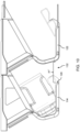
- Referring to
FIGS. 1 and2 , a door assembly according to the present disclosure is shown generally atrefence numeral 100. Thedoor assembly 100 is shown, for example, utilized with an entrance of apassenger suite 102 in an aircraft. Thepassenger suite 102 may be part of a larger seating arrangement including a plurality of adjacent passenger suites. As shown, a portion of the passenger seating arrangement includes longitudinally adjacent passenger suites positioned laterally adjacent an aisle, for instance a longitudinal aisle parallel to an aircraft longitudinal axis. In some embodiments, each suite extends from the longitudinal aisle to the fuselage. In use, thedoor assembly 100 operates to provide access into thesuite 102 and closes for privacy. In some embodiments, thepassenger suite 102 includes apassenger seat 104 and at least one passenger amenity positioned in the suite. - The
passenger suite 102 is defined, at least in part, by at least onepartition wall 106. As shown, a portion of thepartition wall 106 extends along the aisle and a further portion of the partition wall extends behind thepassenger seat 104. In some embodiments, likepartition walls 106 are repeated along the longitudinal length of the passenger cabin for efficiency and to separate and define individual passenger suites. Further portions of thepartition wall 106 may define other spaces within the suite and support mounted structures such as video monitors 108. In some embodiments, the portion of thepartition wall 106 extending along the aisle also extends along a portion of thepassenger seat 104. As shown, thepassenger seat 104 is angled away from the aisle; however, other seat angles are envisioned such as parallel and angled toward the aisle. - The
suite entrance 110 is generally positioned between spaced partition walls, for instance between afirst partition wall 106 associated with a first suite and a spaced apart and longitudinally adjacentsecond partition wall 122 associated with asecond suite 124. In some embodiments, the first partition wall may be associated with thefirst passenger suite 102 and the second partition wall may be associated with a monument, bulkhead, lavatory, etc. positioned longitudinally adjacent the first passenger suite. Thesuite entrance 110 provides ingress and egress directly from the longitudinal aisle such that each suite may have its own dedicated entrance. - With continued reference to
FIG. 1 , thedoor assembly 100 generally includes a slidingdoor 112 and amoveable partition wall 114 configured to support and interact with the door. As shown, a bottom edge of thedoor 112 is spaced above thefloor 116. In use, thedoor 112 translates substantially horizontally forward and aft between open and closed conditions of the door. Assuming thepassenger seat 104 is oriented forward facing, thedoor 112 translates horizontally aft to open and translates horizontally forward to close. Thepartition wall 106 may extend from thefloor 116 to a predetermined height above the floor, preferably above the height of thepassenger seat 104 to enhance privacy for the suite occupant. - The
door assembly 100 generally includes a movable portion of thepartition wall 114, thedoor 112, and a latch mechanism as described further below. Thedoor 112 generally includes afirst door portion 118 and asecond door portion 120, wherein the first and second door portions are configured to be coupled or decoupled depending on the entrance or door opening to be formed.FIGS. 1 and2 show the first andsecond door portions second door portion 120 closest thesecond partition wall 122 may be attached to or positioned proximal the second partition wall, depending on the safety requirements of the door. When thedoor 112 is in the fully closed condition, thefirst door portion 118 is disposed substantially outside and forward of thepartition wall 114, and thesecond door portion 120 is disposed entirely outside of and forward of thepartition wall 114. In some embodiments, each of the first andsecond door portions - Referring to
FIGS. 3 and4 , in a first operating mode thefirst door portion 118 decouples from thesecond door portion 120, via a latch mechanism, and translates or otherwise moves apart from thesecond door portion 120 to form a first entrance ordoor opening 126. Thefirst entrance 126 is formed between the facing edges of the spaced first andsecond door portions first entrance 126 may be formed between the stationarysecond door portion 120 and the facing edge of thepartition wall 114 when thefirst door portion 118 fully retracts into the partition wall. As shown, thefirst entrance 126 has a first width dimension w that corresponds to a standard entrance for use by passengers without mobility limitations. - Referring to
FIGS. 5 and6 , in a second operating mode, themovable partition wall 114 moves relative to thepassenger seat 104 and further apart from the longitudinallyadjacent partition wall 122 to form asecond entrance 128 for accessible use. Thesecond entrance 128 is positioned further aft as compared to the first entrance (126 inFIGS. 3 and4 ) revealing more of thepassenger seat 104 to facilitate lateral transfer. The second entrance has a width dimension w' which is larger than the width dimension w. Comparing thesecond entrance 128 to thefirst entrance 126, the second entrance is not only larger but is longitudinally shifted relative to thesuite 102. As shown, moving thepartition wall 114 aft clears additional space alongside theseat 104 for passenger transfer from the aisle, for instance from a wheelchair to the seat. - As shown, in the second operating mode the
first door 118 may decouple from thesecond door 120 such that the second door remains attached or in otherwise close proximity to thepartition wall 122 of the adjacent suite. Thefirst door 118 may stow within the shiftedpartition wall 114. Mechanisms for shifting the movable portion of thepartition wall 114 relative to stationary portions of thepartition wall 106 may be conventional, such as guide tracks attached to the floor or the stationary partition wall defining engagement surfaces on which sliding or rolling members affixed to the movable partition wall engage. - Referring to
FIGS. 7 and8 , in a modified version of the first operating mode, or as an intermediate mode between the standard and accessible operating modes, themovable partition wall 114 remains stationary and the first andsecond door portions movable partition wall 114 defines an interior space for receiving at least thefirst door portion 118. Alternatively, the coupled first andsecond door portions movable partition wall 114, for instance to the inside of the partition wall apart from the aisle. - In the open-door condition shown in
FIGS. 7 and8 , a differentfirst entrance 130 may be formed between thesecond door portion 120 and theadjacent partition wall 122. The different first entrance has a width w" which may or may not correspond to the width w depending on the amount of aft travel of thedoors movable partition wall 114. In some embodiments, the modified first entrance corresponds to standard use for passengers without mobility limitations. As shown, when open, a minor portion of thefirst door portion 118 and the entirety of thesecond door portion 120 are positioned outside of themovable partition wall 114. -
FIGS. 9 and10 show yet another modifiedentrance 132 formed between themovable partition wall 114 and theadjacent partition wall 122. The modifiedentrance 132 defines a width dimension w‴ which may be greater or equal to at least one of the above widths. In some embodiments, theentrance 130 corresponds to an accessible operating mode in which the reduced mobility passenger requires greater clearance between thepassenger seat 104 andforward partition wall 122 as compared to alongside the passenger seat. As shown, the first door portion is received within the wall as is most of thesecond door portion 120, thereby expanding the entrance width dimension. In a further operating mode, themovable partition wall 114 may shift aft to form an entrance extending between the spacedpartition wall 122 and the facing edge of the shiftedpartition wall 114. - The door assembly as described above is reconfigurable to form different entrances depending on different combinations of the movable partition wall position, coupled state of the first and second door portions, and amount of aft travel of the at least one door portion. For example, the drawing figures show at least one standard operating mode and at least one accessible operating mode. The at least one standard operating mode is achievable by different combinations of coupled and uncoupled states of the first and second door portions and travel relative to the stationary partition wall. The at least one accessible operating mode is achievable by different combinations of partition wall movement, door coupling states and door movements. In all embodiments, the first and second entrances for respective standard and accessible use are different entrances, and not merely one being an extension of the other.
- In a non-limiting use example, the first opening may be formed by maintaining the first position of the movable partition wall and opening at least the first door portion. To create the second opening, the movable partition wall is moved from the first position to the second position and at least the first door portion is moved to the open state. The second opening is not an expansion of the first opening but instead is a newly formed opening longitudinally shifted relative to the first opening. For example, the first opening may extend from the forward wall to about the forward end of the passenger seat, whereas the second opening may extend from about the side of the passenger seat to about the forward wall. In use, the first door may slide the same amount in both operating modes, but once in the closed state, the first and second door portions may be coupled and slide to enlarge the opening further to increase access for reduced mobility passengers.
-
FIGS. 11A and 11B illustrate an exemplary mechanism for coupling and uncoupling the first and second door portions and for attaching and detaching thesecond door portion 120 to the adjacent partition wall. In the mechanism shown, arotating latch 200 andbevel gear arrangement 202 provided on thesecond door portion 120 operates to drive anupper rail 204 and alower rail 206 in opposite directions. Ahook 208 formed on each of the upper andlower rails magnetic lock 210, for example, rotates 90 degrees to attract the first door portion to couple the door portions, and rotates a further 90 degrees to uncouple the first and second door portions. Another mechanism may include a bolt action mechanism wherein a shaft defining sliding bayonet locks slides and rotates to uncouple the door portions and/or the second door portion from its support structure. In further embodiments, the door assembly may be equipped with an emergency release mechanism. - While the foregoing description provides embodiments of the invention by way of example only, it is envisioned that other embodiments may perform similar functions and/or achieve similar results. Any and all such equivalent embodiments and examples are within the scope of the present invention and are intended to be covered by the appended claims.
Claims (9)
- A door assembly (100) for use in an aircraft or other conveyance, comprising:a partition wall (114) configured to move between a first position and a second position;a sliding door (112) including a first door portion (118) and a second door portion (120); anda latch mechanism operable to couple the first and second door portions (118, 120);wherein:in a first operating mode of the door assembly, the partition wall is maintained in the first position and the sliding door moves to an open state to form a first opening;in a second operating mode of the door assembly, the partition wall is moved from the first position to the second position and the sliding door moves to an open state to form a second opening different from the first opening; andthe first opening is not achievable in the second operating mode of the door assembly and the second opening is not achievable in the first operating mode of the door assembly.
- The door assembly according to claim 1, wherein the first operating mode corresponds to standard use and the second operating mode corresponds to accessible use, and wherein the second opening is longitudinally shifted relative to the first opening.
- The door assembly according to claim 1 or 2, wherein the first and second openings have a substantially equal width dimension or wherein a width dimension of the second opening is greater than a width dimension of the first opening.
- The door assembly according to claim 1, wherein in the first operating mode of the door assembly, the first and second door portions uncouple, and the first door portion moves relative the second door portion.
- The door assembly according to any of claims 1-3, wherein in the first operating mode of the door assembly, the first and second door portions are coupled and move together relative to the partition wall.
- The door assembly according to any preceding claim, wherein in the second operating mode of the door assembly, the first and second door portions uncouple, and the first door portion moves relative to the second door portion.
- The door assembly according to any of claims 1-5, wherein in the second operating mode of the door assembly, the first and second door portions are coupled and move together relative to the partition wall.
- The door assembly according to any preceding claim, wherein the latch mechanism includes a rotating level and a bevel gear arrangement.
- A passenger suite (102), comprising:a partition wall (106) defining an interior space;a passenger seat (104) positioned in the interior space;an entrance formed between the partition wall and a spaced structure; anda door assembly (100), as claimed in any preceding claim.
Applications Claiming Priority (1)
| Application Number | Priority Date | Filing Date | Title |
|---|---|---|---|
| US17/833,603 US20230391441A1 (en) | 2022-06-06 | 2022-06-06 | Door assembly with standard and accessible operating modes |
Publications (1)
| Publication Number | Publication Date |
|---|---|
| EP4289741A1 true EP4289741A1 (en) | 2023-12-13 |
Family
ID=86656985
Family Applications (1)
| Application Number | Title | Priority Date | Filing Date |
|---|---|---|---|
| EP23176847.4A Pending EP4289741A1 (en) | 2022-06-06 | 2023-06-01 | Door assembly with standard and accessible operating modes |
Country Status (2)
| Country | Link |
|---|---|
| US (1) | US20230391441A1 (en) |
| EP (1) | EP4289741A1 (en) |
Citations (4)
| Publication number | Priority date | Publication date | Assignee | Title |
|---|---|---|---|---|
| US20140123571A1 (en) * | 2012-11-05 | 2014-05-08 | C&D Zodiac, Inc. | Wheelchair accessible lavatory |
| US20190329891A1 (en) * | 2016-11-15 | 2019-10-31 | Safran Seats Usa Llc | Mini suite emergency egress solutions |
| US20210179271A1 (en) * | 2019-12-11 | 2021-06-17 | Adient Aerospace, Llc | Passenger seating arrangement |
| US20220009636A1 (en) * | 2020-07-10 | 2022-01-13 | B/E Aerospace, Inc. | Modular Multiple-Egress Doors for Dual Occupancy Aircraft Passenger Suites |
Family Cites Families (4)
| Publication number | Priority date | Publication date | Assignee | Title |
|---|---|---|---|---|
| US2910743A (en) * | 1956-08-03 | 1959-11-03 | Lester M Muhn | Operator for louver type windows |
| DE10204343A1 (en) * | 2002-02-01 | 2003-08-07 | Wall Ag | toilet facility |
| WO2016164352A1 (en) * | 2015-04-09 | 2016-10-13 | B/E Aerospace, Inc. | Adjustable sliding screen apparatus |
| US20230365261A1 (en) * | 2022-05-10 | 2023-11-16 | B/E Aerospace, Inc. | Persons with reduced mobility (prm) suite access wall assembly |
-
2022
- 2022-06-06 US US17/833,603 patent/US20230391441A1/en active Pending
-
2023
- 2023-06-01 EP EP23176847.4A patent/EP4289741A1/en active Pending
Patent Citations (4)
| Publication number | Priority date | Publication date | Assignee | Title |
|---|---|---|---|---|
| US20140123571A1 (en) * | 2012-11-05 | 2014-05-08 | C&D Zodiac, Inc. | Wheelchair accessible lavatory |
| US20190329891A1 (en) * | 2016-11-15 | 2019-10-31 | Safran Seats Usa Llc | Mini suite emergency egress solutions |
| US20210179271A1 (en) * | 2019-12-11 | 2021-06-17 | Adient Aerospace, Llc | Passenger seating arrangement |
| US20220009636A1 (en) * | 2020-07-10 | 2022-01-13 | B/E Aerospace, Inc. | Modular Multiple-Egress Doors for Dual Occupancy Aircraft Passenger Suites |
Also Published As
| Publication number | Publication date |
|---|---|
| US20230391441A1 (en) | 2023-12-07 |
Similar Documents
| Publication | Publication Date | Title |
|---|---|---|
| US9714094B2 (en) | Compact aircraft galley and lavatory arrangement and articulating lavatory partition for an aircraft | |
| US9346548B2 (en) | Toilet arrangement for a vehicle | |
| US5816534A (en) | Aircraft cabin divider arrangement | |
| EP3333077B1 (en) | Modular cabin segment, cabin for a vehicle and vehicle with a cabin | |
| US20220332423A1 (en) | Passenger seat unit with multi-track sliding door | |
| EP3589804B1 (en) | Aircraft lavatory complex for people of reduced mobility | |
| CN106660628B (en) | Bulkhead assembly with built-in door for aircraft interior | |
| EP3587244B1 (en) | Slide and rotating cockpit door and method | |
| EP4289741A1 (en) | Door assembly with standard and accessible operating modes | |
| EP3964445A1 (en) | Variable width door for cockpit secondary barrier and other aircraft cabin applications | |
| WO1985002539A1 (en) | Road vehicles | |
| US20130081330A1 (en) | Aircraft interior door assembly | |
| EP3165445A1 (en) | Aircraft door assembly | |
| US20230415897A1 (en) | Flexible aircraft privacy door | |
| EP3290328B1 (en) | Door unit for a means of transport | |
| US20180057168A1 (en) | Lateral linear moving curtain rail | |
| EP4299436A1 (en) | A door locking assembly for an aircraft | |
| EP4140888A1 (en) | Passenger seat arrangement for socialization and access for persons of reduced mobility | |
| JP2024059098A (en) | Privacy door for the interior cabin of the transporter | |
| CA3192370A1 (en) | A door locking assembly for an aircraft |
Legal Events
| Date | Code | Title | Description |
|---|---|---|---|
| PUAI | Public reference made under article 153(3) epc to a published international application that has entered the european phase |
Free format text: ORIGINAL CODE: 0009012 |
|
| STAA | Information on the status of an ep patent application or granted ep patent |
Free format text: STATUS: THE APPLICATION HAS BEEN PUBLISHED |
|
| AK | Designated contracting states |
Kind code of ref document: A1 Designated state(s): AL AT BE BG CH CY CZ DE DK EE ES FI FR GB GR HR HU IE IS IT LI LT LU LV MC ME MK MT NL NO PL PT RO RS SE SI SK SM TR |