EP4289690A1 - Pedal simulator - Google Patents
Pedal simulator Download PDFInfo
- Publication number
- EP4289690A1 EP4289690A1 EP22205833.1A EP22205833A EP4289690A1 EP 4289690 A1 EP4289690 A1 EP 4289690A1 EP 22205833 A EP22205833 A EP 22205833A EP 4289690 A1 EP4289690 A1 EP 4289690A1
- Authority
- EP
- European Patent Office
- Prior art keywords
- unit
- damper
- piston rod
- piston
- disposed
- Prior art date
- Legal status (The legal status is an assumption and is not a legal conclusion. Google has not performed a legal analysis and makes no representation as to the accuracy of the status listed.)
- Granted
Links
Images




Classifications
-
- G—PHYSICS
- G05—CONTROLLING; REGULATING
- G05G—CONTROL DEVICES OR SYSTEMS INSOFAR AS CHARACTERISED BY MECHANICAL FEATURES ONLY
- G05G5/00—Means for preventing, limiting or returning the movements of parts of a control mechanism, e.g. locking controlling member
- G05G5/03—Means for enhancing the operator's awareness of arrival of the controlling member at a command or datum position; Providing feel, e.g. means for creating a counterforce
-
- B—PERFORMING OPERATIONS; TRANSPORTING
- B60—VEHICLES IN GENERAL
- B60T—VEHICLE BRAKE CONTROL SYSTEMS OR PARTS THEREOF; BRAKE CONTROL SYSTEMS OR PARTS THEREOF, IN GENERAL; ARRANGEMENT OF BRAKING ELEMENTS ON VEHICLES IN GENERAL; PORTABLE DEVICES FOR PREVENTING UNWANTED MOVEMENT OF VEHICLES; VEHICLE MODIFICATIONS TO FACILITATE COOLING OF BRAKES
- B60T7/00—Brake-action initiating means
- B60T7/02—Brake-action initiating means for personal initiation
- B60T7/04—Brake-action initiating means for personal initiation foot actuated
- B60T7/042—Brake-action initiating means for personal initiation foot actuated by electrical means, e.g. using travel or force sensors
-
- B—PERFORMING OPERATIONS; TRANSPORTING
- B60—VEHICLES IN GENERAL
- B60T—VEHICLE BRAKE CONTROL SYSTEMS OR PARTS THEREOF; BRAKE CONTROL SYSTEMS OR PARTS THEREOF, IN GENERAL; ARRANGEMENT OF BRAKING ELEMENTS ON VEHICLES IN GENERAL; PORTABLE DEVICES FOR PREVENTING UNWANTED MOVEMENT OF VEHICLES; VEHICLE MODIFICATIONS TO FACILITATE COOLING OF BRAKES
- B60T13/00—Transmitting braking action from initiating means to ultimate brake actuator with power assistance or drive; Brake systems incorporating such transmitting means, e.g. air-pressure brake systems
- B60T13/74—Transmitting braking action from initiating means to ultimate brake actuator with power assistance or drive; Brake systems incorporating such transmitting means, e.g. air-pressure brake systems with electrical assistance or drive
-
- B—PERFORMING OPERATIONS; TRANSPORTING
- B60—VEHICLES IN GENERAL
- B60T—VEHICLE BRAKE CONTROL SYSTEMS OR PARTS THEREOF; BRAKE CONTROL SYSTEMS OR PARTS THEREOF, IN GENERAL; ARRANGEMENT OF BRAKING ELEMENTS ON VEHICLES IN GENERAL; PORTABLE DEVICES FOR PREVENTING UNWANTED MOVEMENT OF VEHICLES; VEHICLE MODIFICATIONS TO FACILITATE COOLING OF BRAKES
- B60T7/00—Brake-action initiating means
- B60T7/02—Brake-action initiating means for personal initiation
- B60T7/04—Brake-action initiating means for personal initiation foot actuated
-
- B—PERFORMING OPERATIONS; TRANSPORTING
- B60—VEHICLES IN GENERAL
- B60T—VEHICLE BRAKE CONTROL SYSTEMS OR PARTS THEREOF; BRAKE CONTROL SYSTEMS OR PARTS THEREOF, IN GENERAL; ARRANGEMENT OF BRAKING ELEMENTS ON VEHICLES IN GENERAL; PORTABLE DEVICES FOR PREVENTING UNWANTED MOVEMENT OF VEHICLES; VEHICLE MODIFICATIONS TO FACILITATE COOLING OF BRAKES
- B60T7/00—Brake-action initiating means
- B60T7/02—Brake-action initiating means for personal initiation
- B60T7/04—Brake-action initiating means for personal initiation foot actuated
- B60T7/06—Disposition of pedal
-
- B—PERFORMING OPERATIONS; TRANSPORTING
- B60—VEHICLES IN GENERAL
- B60T—VEHICLE BRAKE CONTROL SYSTEMS OR PARTS THEREOF; BRAKE CONTROL SYSTEMS OR PARTS THEREOF, IN GENERAL; ARRANGEMENT OF BRAKING ELEMENTS ON VEHICLES IN GENERAL; PORTABLE DEVICES FOR PREVENTING UNWANTED MOVEMENT OF VEHICLES; VEHICLE MODIFICATIONS TO FACILITATE COOLING OF BRAKES
- B60T8/00—Arrangements for adjusting wheel-braking force to meet varying vehicular or ground-surface conditions, e.g. limiting or varying distribution of braking force
- B60T8/32—Arrangements for adjusting wheel-braking force to meet varying vehicular or ground-surface conditions, e.g. limiting or varying distribution of braking force responsive to a speed condition, e.g. acceleration or deceleration
- B60T8/34—Arrangements for adjusting wheel-braking force to meet varying vehicular or ground-surface conditions, e.g. limiting or varying distribution of braking force responsive to a speed condition, e.g. acceleration or deceleration having a fluid pressure regulator responsive to a speed condition
- B60T8/40—Arrangements for adjusting wheel-braking force to meet varying vehicular or ground-surface conditions, e.g. limiting or varying distribution of braking force responsive to a speed condition, e.g. acceleration or deceleration having a fluid pressure regulator responsive to a speed condition comprising an additional fluid circuit including fluid pressurising means for modifying the pressure of the braking fluid, e.g. including wheel driven pumps for detecting a speed condition, or pumps which are controlled by means independent of the braking system
- B60T8/4072—Systems in which a driver input signal is used as a control signal for the additional fluid circuit which is normally used for braking
- B60T8/4081—Systems with stroke simulating devices for driver input
- B60T8/409—Systems with stroke simulating devices for driver input characterised by details of the stroke simulating device
-
- B—PERFORMING OPERATIONS; TRANSPORTING
- B60—VEHICLES IN GENERAL
- B60Y—INDEXING SCHEME RELATING TO ASPECTS CROSS-CUTTING VEHICLE TECHNOLOGY
- B60Y2410/00—Constructional features of vehicle sub-units
- B60Y2410/10—Housings
-
- G—PHYSICS
- G05—CONTROLLING; REGULATING
- G05G—CONTROL DEVICES OR SYSTEMS INSOFAR AS CHARACTERISED BY MECHANICAL FEATURES ONLY
- G05G2505/00—Means for preventing, limiting or returning the movements of parts of a control mechanism, e.g. locking controlling member
Definitions
- Exemplary embodiments of the present disclosure relate to a pedal simulator, and more particularly, to a pedal simulator applicable to all types of pedals regardless of type and shape of the pedal.
- a pedal simulator is a part mounted on an electro-mechanical brake (EMB), and provides a driver with the braking feeling generated from an existing mechanical brake.
- EMB electro-mechanical brake
- a pedal may be divided into an organ-type pedal and a pendant-type pedal.
- a pedal simulator had to be newly developed according to types and layouts of a pedal. Since a separate pedal simulator is required depending on the types of a pedal, production cost increases, and repair is difficult. Therefore, there is a need to solve the problems.
- Various embodiments are directed to a pedal simulator capable of improving valid and invalid strokes and a braking feeling.
- a pedal simulator includes: a housing having an inner space; a piston part slidably disposed at the inner space of the housing and including a plurality of piston rod units; and a plurality of damper parts disposed at the housing and facing the plurality of piston rod units, respectively, wherein each of the damper parts is configured to be compressed by a pressure from a respective one among the piston rod units.
- Each damper part is configured to be compressed by the respective piston rod unit at a different time.
- the plurality of damper parts includes first and second damper parts
- the piston part further includes: a piston body unit having first and second sides; and a piston pressing unit disposed at the first side of the piston body unit
- the plurality of piston rod units includes: a first piston rod unit disposed at the second side of the piston body unit and configured to press the first damper part; and a second piston rod unit disposed at the second side of the piston body unit, spaced apart from the first piston rod unit and configured to press the second damper part.
- the first and second piston rod units have respectively different lengths.
- the first damper part is disposed to face the first piston rod unit and compressed by the pressure from the first piston rod unit
- the second damper part is disposed to face the second piston rod unit, spaced apart from the first damper part, and compressed by the pressure from the second piston rod unit.
- the first damper part includes: a first damper body unit disposed at the housing; a first damper contact unit spaced apart from the first damper body unit and configured to move by the first piston rod unit in contact with the first damper contact unit; a connection unit having a first side movably disposed on the first damper body unit and a second side disposed on the first damper contact unit; a sensor unit disposed on the first damper body unit and configured to detect a position of the first piston rod unit; and a spring unit having a first side in contact with the first damper body unit and a second side in contact with the first damper contact unit, and configured to provide an elastic force to the first damper contact unit.
- connection unit includes: a connection block unit movably disposed at the first damper body unit; and a connection rod unit having a first side disposed on the connection block unit and a second side disposed on the first damper contact unit.
- the second damper part comprises an elastically deformable material and couped to the housing
- the piston pressing unit is rotatably coupled to the piston body unit.
- a pedal simulator includes: a housing detachably disposed on a pedal part and having an inner space; a piston part slidably disposed at the inner space of the housing and including a plurality of piston rod units; and a plurality of damper parts disposed at the housing and facing the plurality of piston rod units, respectively, wherein each of the damper parts is compressed by a pressure from a respective one of the piston rod units.
- the housing includes: a housing body part configured to movably accommodate the piston part, wherein the plurality of damper parts is disposed at the housing body part; and a hook part disposed on an outer side of the housing body part and detachably coupled to the pedal part.
- the hook part comprises a plurality of hook parts disposed at an edge of the housing body part.
- the pedal simulator according to the present disclosure enables common use of products through modularization applicable to all pedal parts regardless of types and shapes of a pedal part.
- first and second piston rod units are tunable so that a user can have appropriate initial and medium period braking feelings and an appropriate later period braking feeling.
- Effects of the present disclosure are not limited to the aforementioned effects, and may include various effects within a range evident to those skilled in the art from the following description.
- FIG. 1 is a perspective view schematically illustrating that a pedal simulator according to the present disclosure is mounted (or disposed) on an organ-type pedal part
- FIG. 2 is a perspective view schematically illustrating that the pedal simulator according to the present disclosure is mounted on a pendant-type pedal part
- FIG. 3 is a perspective view schematically illustrating the pedal simulator according to the present disclosure
- FIG. 4 is an assembled perspective view schematically illustrating the pedal simulator according to the present disclosure
- FIG. 5 is a cross-sectional view schematically illustrating the pedal simulator according to an embodiment of the present disclosure
- FIG. 6 is a perspective view schematically illustrating a piston part according to the present disclosure
- FIG. 7 is a cross-sectional view schematically illustrating the piston part according to the present disclosure
- FIG. 1 is a perspective view schematically illustrating that a pedal simulator according to the present disclosure is mounted (or disposed) on an organ-type pedal part
- FIG. 2 is a perspective view schematically illustrating that the pedal simulator according to the present disclosure is mounted on
- FIG. 8 is a cross-sectional view schematically illustrating that a piston pressing unit is coupled to a piston body unit by caulking in the piston part according to the present disclosure
- FIG. 9 is a perspective view schematically illustrating a first damper part according to the present disclosure
- FIG. 10 is a cross-sectional view schematically illustrating initial and intermediate braking in the pedal simulator according to the present disclosure
- FIG. 11 is a cross-sectional view schematically illustrating later braking in the pedal simulator according to the present disclosure.
- a pedal simulator 1 may be detachably mounted on pedal parts 10a and 10b regardless of types and shapes of the pedal parts 10a and 10b, such as an organ-type pedal part 10a and a pendant-type pedal part 10b.
- the pedal simulator 1 according to the present disclosure is modularized and easily assembled into the pedal parts 10a and 10b such as the organ-type pedal part 10a and the pendant-type pedal part 10b. Since the pedal simulator 1 according to the present disclosure is applicable to all the pedal parts 10a and 10b, common use of the pedal simulator 1 may be achieved.
- a hook part 120 of a housing 100 is hook-coupled to an insertion hole part 11a of the organ-type pedal part 10a so that the pedal simulator 1 may be easily assembled into the organ-type pedal part 10a.
- the hook part 120 of the housing 100 is hook-coupled to an insertion hole part 11b of the pendant-type pedal part 10b so that the pedal simulator 1 may be easily assembled into the pendant-type pedal part 10b.
- the pedal simulator 1 according to an embodiment of the present disclosure includes the housing 100, a piston part 200 and damper parts 300.
- the housing 100 is mounted on the pedal parts 10a and 10b, such as the organ-type pedal part 10a and the pendant-type pedal part 10b.
- the damper parts 300 are mounted in an inner space of the housing 100, and the housing 100 movably accommodates the piston part 200.
- the housing 100 may be detachably mounted on the pedal parts 10a and 10b, such as the organ-type pedal part 10a and the pendant-type pedal part 10b.
- the housing 100 includes a housing body part 110 and the hook part 120.
- the damper parts 300 are mounted on one side of the housing body part 110, i.e., an inner left surface of the housing body part 110 in FIG. 5 .
- the piston part 200 is movably accommodated in the housing body part 110.
- the housing body part 110 includes a first guide unit 111 and a second guide unit 113 into which the piston part 200 can slide.
- the first guide unit 111 and the second guide unit 113 are formed as cylindrical grooves.
- a first damper part 310 of the damper parts 300 is mounted in the first guide unit 111.
- a first piston rod unit 230 of the piston part 200 is slidably disposed in an inner space of the first guide unit 111.
- An inner diameter of the first guide unit 111 is formed to be larger than an outer diameter of the first piston rod unit 230.
- a second damper part 320 of the damper parts 300 is mounted in the second guide unit 113.
- a second piston rod unit 240 of the piston part 200 is slidably disposed in an inner space of the second guide unit 113.
- An inner diameter of the second guide unit 113 is formed to be larger than an outer diameter of the second piston rod unit 240.
- the hook part 120 is formed in a ring shape on an outer side of the housing body part 110, and is detachably coupled to the insertion hole parts 11a and 11b of the organ-type and pendant-type pedal parts 10a and 10b.
- the hook part 120 may be conveniently assembled and mounted onto the pedal parts 10a and 10b, such as the organ-type pedal part 10a and the pendant-type pedal part 10b.
- the hook part 120 may be provided as a plurality of hook parts 120 which are formed at predetermined intervals on an edge of the housing body part 110.
- the plurality of hook parts 120 may be formed on the housing body part 110, and accordingly, insertion hole parts 11a and 11b of the pedal parts 10a and 10b may also be provided as a plurliaty of insertion hole parts 11a and 11b. Therefore, since the hook parts 120 and the insertion hole parts 11a and 11b of the pedal parts 10a and 10b are coupled at a plurality of points, the pedal simulator 1 and the pedal parts 10a and 10b may be stably coupled, and the rotation or movement of the pedal simulator 1 may be prevented.
- the piston part 200 is slidably mounted in the inner space of the housing 100.
- the piston part 200 includes a piston body unit 210, a piston pressing unit 220, the first piston rod unit 230 and the second piston rod unit 240.
- the piston body unit 210 is disposed on the outer side of the housing body part 110 of the housing 100.
- the piston body unit 210 includes a plate and a rod protruding from the plate to the opposite side of the housing body part 110.
- the rod of the piston body unit 210 is formed with a hollow groove so that the piston pressing unit 220 can be mounted. That is, as illustrated in FIG. 8 , the piston pressing unit 220 is mounted in the rod of the piston body unit 210, specifically, the hollow groove of the rod. The piston pressing unit 220 is moved to the left (refer to FIG. 5 ) by an external force.
- the piston pressing unit 220 is coupled to the piston body unit 210 by caulking. That is, as the rim of the rod of the piston body unit 210 is pressed and caulked toward the piston pressing unit 220, the piston pressing unit 220 moved by the external force may be kept rotatably coupled to the rod of the piston body unit 210.
- the first piston rod unit 230 is mounted on the other side of the piston body unit 210, i.e., a left side of the piston body unit 210 in FIG. 6 .
- the piston pressing unit 220 is mounted on one side of the piston body unit 210, and the first piston rod unit 230 and the second piston rod unit 240 are mounted on the other side of the piston body unit 210, which is opposite to one side of the piston body unit 210.
- the first piston rod unit 230 presses any one of a pair of damper parts 300. That is, the first piston rod unit 230 presses the first damper part 310 of the damper parts 300.
- the second piston rod unit 240 is mounted on the other side of the piston body unit 210, i.e., the left side of the piston body unit 210 in FIG. 6 , so as to be spaced apart from the first piston rod unit 230, and presses the other one of the pair of damper parts 300. That is, the second piston rod unit 240 presses the second damper part 320 of the damper parts 300.
- the first piston rod unit 230 and the second piston rod unit 240 are formed in a cylindrical shape and to have different lengths.
- the first piston rod unit 230 and the second piston rod unit 240 are spaced apart from each other and disposed in parallel on the piston body unit 210.
- the first piston rod unit 230 presses the first damper part 310
- the second piston rod unit 240 presses the second damper part 320. Since the first piston rod unit 230 and the second piston rod unit 240 are formed to have different lengths, the timing at which the first piston rod unit 230 comes into contact with the first damper part 310 and the timing at which the second piston rod unit 240 comes into contact with the second damper part 320 may be different from each other.
- a braking feeling felt by a user may be different, which makes it possible to provide initial and medium period braking feelings and a later period braking feeling.
- a length L1 of the first piston rod unit 230 is formed to be shorter than a length L2 of the second piston rod unit 240.
- the first damper part 310 protrudes more toward the piston part 200 than the second damper part 320.
- the first piston rod unit 230 is disposed in the housing body part 110 so as to face the first damper part 310, and is moved toward the first damper part 310 and presses the first damper part 310 when the external force is applied thereto.
- the second piston rod unit 240 is disposed in the housing body part 110 so as to face the second damper part 320, and is moved toward the second damper part 320 and presses the second damper part 320 when the external force is applied thereto.
- the second piston rod unit 240 and the second damper part 320 are spaced apart from each other, and similarly, the first piston rod unit 230 and the first damper part 310 are spaced apart from each other.
- a separation distance between the first piston rod unit 230 and the first damper part 310 is shorter than a separation distance between the second piston rod unit 240 and the second damper part 320.
- the first piston rod unit 230 and the second piston rod unit 240 are moved by the movement of the piston part 200, the first piston rod unit 230 comes into contact with the first damper part 310 first. In this case, the second piston rod unit 240 is not yet in contact with the second damper part 320 (refer to FIG. 10 ).
- the first piston rod unit 230 is moved to come into contact with the first damper part 310, and provides a braking operation starting force while the first piston rod unit 230 is further moved to press the first damper part 310.
- the first piston rod unit 230 may be provided the user with an initial period braking feeling and a medium period braking feeling.
- the second piston rod unit 240 When the movement of the piston part 200 further increases, the second piston rod unit 240 also comes into contact with the second damper part 320 (refer to FIG. 11 ). While the first piston rod unit 230 is already in contact with the first damper part 310, the second piston rod unit 240 comes into contact with the second damper part 320, thereby providing the user with a later period braking feeling.
- the length L1 of the first piston rod unit 230 and the length L2 of the second piston rod unit 240 are tunable to provide the user with an appropriate braking feeling.
- the damper part 300 is provided as a plurality of damper parts 300 that are mounted in the housing 100, and are compressed by being pressed by the piston part 200.
- the plurality of damper parts 300 include the first damper part 310 and the second damper part 320, and are mounted in the housing 100.
- the first damper part 310 is disposed to face the first piston rod unit 230, and is mounted in the first guide unit 111 of the housing 100.
- the first damper part 310 is formed to protrude more toward the piston part 200 than the second damper part 320.
- the first damper part 310 includes a first damper body unit 311, a first damper contact unit 313, a connection unit 315, a sensor unit 317 and a spring unit 319.
- the first damper body unit 311 is mounted in the first guide unit 111 of the housing body part 110.
- the first damper body unit 311 may be fixed to the first guide unit 111 of the housing body part 110 by bolting, bonding, press-fitting or the like.
- the first damper contact unit 313 is disposed to be spaced apart from the first damper body unit 311, and comes in contact with the first piston rod unit 230 which moves. Even though the first piston rod unit 230 moves, the braking operation is not performed until the first piston rod unit 230 comes into contact with the first damper contact unit 313. Therefore, such a period that the braking operation is not performed is referred to as an invalid period of braking. A period in which the first piston rod unit 230 is moved further and comes into contact with the first damper contact unit 313 is referred to as a valid period of braking.
- connection unit 315 One side of the connection unit 315, i.e., a left side of the connection unit 315 in FIG. 4 , is movably mounted in the first damper body unit 311, and the other side of the connection unit 315, i.e., a right side of the connection unit 315 in FIG. 4 , is mounted on the first damper contact unit 313.
- the connection unit 315 includes a connection block unit 315a and a connection rod unit 315b.
- connection block unit 315a is movably mounted in the first damper body unit 311.
- the connection block unit 315a may be moved in an inner space of the first damper body unit 311 by the pressure from the first piston rod unit 230 transmitted through the connection rod unit 315b.
- the connection block unit 315a may be formed of rubber, plastic or the like.
- connection rod unit 315b is formed in a rod shape in which one side thereof, i.e., a left side thereof in FIG. 4 is mounted on the connection block unit 315a, and the other side thereof, i.e., a right side thereof FIG. 4 is mounted on the first damper contact unit 313.
- the sensor unit 317 is mounted on an outer surface of the first damper contact unit 313, and measuresinformation on a position of the first piston rod unit 230.
- the sensor unit 317 includes a magnet having a magnetic force.
- the sensor unit 317 measures information on magnitude of a stepping force applied by the first piston rod unit 230 or a position of the first piston rod unit 230 through a change in a magnetic field that is changed according to the movement of the first piston rod unit 230, and provides a control unit (not illustrated) with the measured information.
- One side of the spring unit 319 i.e., a left side of the spring unit 319 in FIG. 4
- the other side of the spring unit 319 i.e., a right side of the spring unit 319 in FIG. 4
- the spring unit 319 provides an elastic force to the first damper contact unit 313 moved by the first piston rod unit 230.
- the spring unit 319 is interposed between the first damper body unit 311 and the first damper contact unit 313, and is compressed by the first damper contact unit 313 pressed by the first piston rod unit 230.
- the compressed spring unit 319 When the pressing force of the first piston rod unit 230 is released, the compressed spring unit 319 provides the first damper contact unit 313 with an elastic force, i.e., an elastic restoring force, and returns the first damper contact unit 313 to its original position.
- the spring unit 319 may be formed of a coil spring that surrounds an outer side of the connection rod unit 315b.
- the second damper part 320 is disposed to face the second piston rod unit 240, and is mounted in parallel so as to be spaced apart from the first damper part 310 in the housing 100.
- the second damper part 320 is mounted in the second guide unit 113 of the housing body part 110.
- the second damper part 320 is formed of an elastically deformable material, and is coupled to the second guide unit 113 of the housing body part 110 of the housing 100 by press-fitting.
- the second damper part 320 may be coupled to the housing 100 in the press-fitting way and may be easily assembled thereto.
- the piston body unit 210 is moved, and accordingly, the first piston rod unit 230 and the second piston rod unit 240 are moved toward the first damper part 310 and the second damper part 320, respectively.
- the first piston rod unit 230 is moved along the first guide unit 111
- the second piston rod unit 240 is moved along the second guide unit 113.
- the user may have an initial period braking feeling when the first piston rod unit 230 presses the first damper contact unit 313.
- the spring unit 319 is compressed and deformed so that the user may have a medium period braking feeling.
- the sensor unit 317 transmits information on a position or stepping force of the first piston rod unit 230 according to a change in a magnetic field to the control unit (not illustrated).
- the second damper part 320 may be formed of an elastically deformable material including rubber, silicone or plastic, or a combination thereof. Therefore, when the second piston rod unit 240 comes into contact with the second damper part 320, the user feels harder. Accordingly, the user may recognize that the braking is completed when the second piston rod unit 240 comes into contact with the second damper part 320.
- the compressed spring unit 319 provides the first damper contact unit 313 with an elastic force, i.e., an elastic restoring force, and returns the first damper contact unit 313 to its original position.
- the pedal simulator 1 enables common use of products through modularization applicable to all pedal parts regardless of types and shapes of the pedal parts 10a and 10b.
- the first and second piston rod units are tunable so that a user can have appropriate initial and medium period braking feelings and an appropriate later period braking feeling.
Landscapes
- Engineering & Computer Science (AREA)
- Transportation (AREA)
- Mechanical Engineering (AREA)
- Physics & Mathematics (AREA)
- Fluid Mechanics (AREA)
- General Physics & Mathematics (AREA)
- Automation & Control Theory (AREA)
- Mechanical Control Devices (AREA)
- Braking Elements And Transmission Devices (AREA)
- Regulating Braking Force (AREA)
Abstract
Description
- Exemplary embodiments of the present disclosure relate to a pedal simulator, and more particularly, to a pedal simulator applicable to all types of pedals regardless of type and shape of the pedal.
- A pedal simulator is a part mounted on an electro-mechanical brake (EMB), and provides a driver with the braking feeling generated from an existing mechanical brake.
- In the prior art, a hydraulic system is applied to the EMB. However, as technologies related to an electro-mechanical brake system, i.e., a Brake-By-Wire System, and an autonomous vehicle have recently emerged, the development of a non-hydraulic brake system is required.
- A pedal may be divided into an organ-type pedal and a pendant-type pedal. In the prior art, a pedal simulator had to be newly developed according to types and layouts of a pedal. Since a separate pedal simulator is required depending on the types of a pedal, production cost increases, and repair is difficult. Therefore, there is a need to solve the problems.
- The background technology of the present disclosure is disclosed in
Korean Patent No. 10-2223847 (February 26, 2021 - Various embodiments are directed to a pedal simulator capable of improving valid and invalid strokes and a braking feeling.
- In an embodiment, a pedal simulator includes: a housing having an inner space; a piston part slidably disposed at the inner space of the housing and including a plurality of piston rod units; and a plurality of damper parts disposed at the housing and facing the plurality of piston rod units, respectively, wherein each of the damper parts is configured to be compressed by a pressure from a respective one among the piston rod units.
- Each damper part is configured to be compressed by the respective piston rod unit at a different time.
- The plurality of damper parts includes first and second damper parts, the piston part further includes: a piston body unit having first and second sides; and a piston pressing unit disposed at the first side of the piston body unit, and the plurality of piston rod units includes: a first piston rod unit disposed at the second side of the piston body unit and configured to press the first damper part; and a second piston rod unit disposed at the second side of the piston body unit, spaced apart from the first piston rod unit and configured to press the second damper part.
- The first and second piston rod units have respectively different lengths.
- The first damper part is disposed to face the first piston rod unit and compressed by the pressure from the first piston rod unit, and the second damper part is disposed to face the second piston rod unit, spaced apart from the first damper part, and compressed by the pressure from the second piston rod unit.
- The first damper part includes: a first damper body unit disposed at the housing; a first damper contact unit spaced apart from the first damper body unit and configured to move by the first piston rod unit in contact with the first damper contact unit; a connection unit having a first side movably disposed on the first damper body unit and a second side disposed on the first damper contact unit; a sensor unit disposed on the first damper body unit and configured to detect a position of the first piston rod unit; and a spring unit having a first side in contact with the first damper body unit and a second side in contact with the first damper contact unit, and configured to provide an elastic force to the first damper contact unit.
- The connection unit includes: a connection block unit movably disposed at the first damper body unit; and a connection rod unit having a first side disposed on the connection block unit and a second side disposed on the first damper contact unit.
- The second damper part comprises an elastically deformable material and couped to the housing
- The piston pressing unit is rotatably coupled to the piston body unit.
- In an embodiment, a pedal simulator includes: a housing detachably disposed on a pedal part and having an inner space; a piston part slidably disposed at the inner space of the housing and including a plurality of piston rod units; and a plurality of damper parts disposed at the housing and facing the plurality of piston rod units, respectively, wherein each of the damper parts is compressed by a pressure from a respective one of the piston rod units.
- The housing includes: a housing body part configured to movably accommodate the piston part, wherein the plurality of damper parts is disposed at the housing body part; and a hook part disposed on an outer side of the housing body part and detachably coupled to the pedal part.
- The hook part comprises a plurality of hook parts disposed at an edge of the housing body part.
- The pedal simulator according to the present disclosure enables common use of products through modularization applicable to all pedal parts regardless of types and shapes of a pedal part.
- Since various types of pedal parts due to modularization according to the present disclosure come into common use, repair and replacement of products can be reduced, and productivity can be improved.
- In addition, according to the present disclosure, as a first piston rod unit and a second piston rod unit are formed to have different lengths, the first and second piston rod units are tunable so that a user can have appropriate initial and medium period braking feelings and an appropriate later period braking feeling.
- Moreover, according to the present disclosure, it is possible to reduce the volume of a housing through parallel structures of first and second piston rod units and first and second damper parts.
- Effects of the present disclosure are not limited to the aforementioned effects, and may include various effects within a range evident to those skilled in the art from the following description.
-
-
FIG. 1 is a perspective view schematically illustrating that a pedal simulator according to the present disclosure is mounted on an organ-type pedal part. -
FIG. 2 is a perspective view schematically illustrating that the pedal simulator according to the present disclosure is mounted on a pendant-type pedal part. -
FIG. 3 is a perspective view schematically illustrating the pedal simulator according to the present disclosure. -
FIG. 4 is an assembled perspective view schematically illustrating the pedal simulator according to the present disclosure. -
FIG. 5 is a cross-sectional view schematically illustrating the pedal simulator according to the present disclosure. -
FIG. 6 is a perspective view schematically illustrating a piston part according to the present disclosure. -
FIG. 7 is a cross-sectional view schematically illustrating the piston part according to the present disclosure. -
FIG. 8 is a cross-sectional view schematically illustrating that a piston pressing unit is coupled to a piston body unit in a caulking way in the piston part according to the present disclosure. -
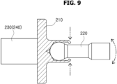
FIG. 9 is a perspective view schematically illustrating a first damper part according to the present disclosure. -
FIG. 10 is a cross-sectional view schematically illustrating initial and intermediate braking in the pedal simulator according to the present disclosure. -
FIG. 11 is a cross-sectional view schematically illustrating later braking in the pedal simulator according to the present disclosure. - Hereinafter, a pedal simulator will be described in detail with reference to the accompanying drawings through various exemplary embodiments. In such a process, the thicknesses of lines or the sizes of elements illustrated in the drawings may have been exaggerated for the clarity of a description and for convenience' sake.
- Terms to be described below have been defined by taking into consideration their functions in the present disclosure, and may be changed depending on a user or operator's intention or practice. Accordingly, such terms should be defined based on the overall contents of this specification.
-
FIG. 1 is a perspective view schematically illustrating that a pedal simulator according to the present disclosure is mounted (or disposed) on an organ-type pedal part,FIG. 2 is a perspective view schematically illustrating that the pedal simulator according to the present disclosure is mounted on a pendant-type pedal part,FIG. 3 is a perspective view schematically illustrating the pedal simulator according to the present disclosure,FIG. 4 is an assembled perspective view schematically illustrating the pedal simulator according to the present disclosure,FIG. 5 is a cross-sectional view schematically illustrating the pedal simulator according to an embodiment of the present disclosure,FIG. 6 is a perspective view schematically illustrating a piston part according to the present disclosure,FIG. 7 is a cross-sectional view schematically illustrating the piston part according to the present disclosure,FIG. 8 is a cross-sectional view schematically illustrating that a piston pressing unit is coupled to a piston body unit by caulking in the piston part according to the present disclosure,FIG. 9 is a perspective view schematically illustrating a first damper part according to the present disclosure,FIG. 10 is a cross-sectional view schematically illustrating initial and intermediate braking in the pedal simulator according to the present disclosure, andFIG. 11 is a cross-sectional view schematically illustrating later braking in the pedal simulator according to the present disclosure. - Referring to
FIGS. 1 and2 , apedal simulator 1 according to the present disclosure may be detachably mounted onpedal parts pedal parts type pedal part 10a and a pendant-type pedal part 10b. - Therefore, the
pedal simulator 1 according to the present disclosure is modularized and easily assembled into thepedal parts type pedal part 10a and the pendant-type pedal part 10b. Since thepedal simulator 1 according to the present disclosure is applicable to all thepedal parts pedal simulator 1 may be achieved. - A
hook part 120 of ahousing 100 is hook-coupled to aninsertion hole part 11a of the organ-type pedal part 10a so that thepedal simulator 1 may be easily assembled into the organ-type pedal part 10a. - In addition, the
hook part 120 of thehousing 100 is hook-coupled to aninsertion hole part 11b of the pendant-type pedal part 10b so that thepedal simulator 1 may be easily assembled into the pendant-type pedal part 10b. - Referring to
FIGS. 3 to 5 , thepedal simulator 1 according to an embodiment of the present disclosure includes thehousing 100, apiston part 200 anddamper parts 300. - In the present embodiment, the
housing 100 is mounted on thepedal parts type pedal part 10a and the pendant-type pedal part 10b. Thedamper parts 300 are mounted in an inner space of thehousing 100, and thehousing 100 movably accommodates thepiston part 200. - The
housing 100 may be detachably mounted on thepedal parts type pedal part 10a and the pendant-type pedal part 10b. - The
housing 100 includes ahousing body part 110 and thehook part 120. Thedamper parts 300 are mounted on one side of thehousing body part 110, i.e., an inner left surface of thehousing body part 110 inFIG. 5 . - The
piston part 200 is movably accommodated in thehousing body part 110. Thehousing body part 110 includes afirst guide unit 111 and asecond guide unit 113 into which thepiston part 200 can slide. Thefirst guide unit 111 and thesecond guide unit 113 are formed as cylindrical grooves. - A
first damper part 310 of thedamper parts 300 is mounted in thefirst guide unit 111. A firstpiston rod unit 230 of thepiston part 200 is slidably disposed in an inner space of thefirst guide unit 111. An inner diameter of thefirst guide unit 111 is formed to be larger than an outer diameter of the firstpiston rod unit 230. - A
second damper part 320 of thedamper parts 300 is mounted in thesecond guide unit 113. A secondpiston rod unit 240 of thepiston part 200 is slidably disposed in an inner space of thesecond guide unit 113. An inner diameter of thesecond guide unit 113 is formed to be larger than an outer diameter of the secondpiston rod unit 240. - The
hook part 120 is formed in a ring shape on an outer side of thehousing body part 110, and is detachably coupled to theinsertion hole parts type pedal parts hook part 120 may be conveniently assembled and mounted onto thepedal parts type pedal part 10a and the pendant-type pedal part 10b. - The
hook part 120 may be provided as a plurality ofhook parts 120 which are formed at predetermined intervals on an edge of thehousing body part 110. The plurality ofhook parts 120 may be formed on thehousing body part 110, and accordingly,insertion hole parts pedal parts insertion hole parts hook parts 120 and theinsertion hole parts pedal parts pedal simulator 1 and thepedal parts pedal simulator 1 may be prevented. - Referring to
FIGS. 6 to 8 , thepiston part 200 is slidably mounted in the inner space of thehousing 100. Thepiston part 200 includes apiston body unit 210, apiston pressing unit 220, the firstpiston rod unit 230 and the secondpiston rod unit 240. - The
piston body unit 210 is disposed on the outer side of thehousing body part 110 of thehousing 100. Thepiston body unit 210 includes a plate and a rod protruding from the plate to the opposite side of thehousing body part 110. - The rod of the
piston body unit 210 is formed with a hollow groove so that thepiston pressing unit 220 can be mounted. That is, as illustrated inFIG. 8 , thepiston pressing unit 220 is mounted in the rod of thepiston body unit 210, specifically, the hollow groove of the rod. Thepiston pressing unit 220 is moved to the left (refer toFIG. 5 ) by an external force. - Referring to
FIGS. 8 and9 , thepiston pressing unit 220 is coupled to thepiston body unit 210 by caulking. That is, as the rim of the rod of thepiston body unit 210 is pressed and caulked toward thepiston pressing unit 220, thepiston pressing unit 220 moved by the external force may be kept rotatably coupled to the rod of thepiston body unit 210. - Since the
piston pressing unit 220 is caulked to thepiston body unit 210, assembly time and cost may be reduced. - The first
piston rod unit 230 is mounted on the other side of thepiston body unit 210, i.e., a left side of thepiston body unit 210 inFIG. 6 . Thepiston pressing unit 220 is mounted on one side of thepiston body unit 210, and the firstpiston rod unit 230 and the secondpiston rod unit 240 are mounted on the other side of thepiston body unit 210, which is opposite to one side of thepiston body unit 210. - The first
piston rod unit 230 presses any one of a pair ofdamper parts 300. That is, the firstpiston rod unit 230 presses thefirst damper part 310 of thedamper parts 300. - The second
piston rod unit 240 is mounted on the other side of thepiston body unit 210, i.e., the left side of thepiston body unit 210 inFIG. 6 , so as to be spaced apart from the firstpiston rod unit 230, and presses the other one of the pair ofdamper parts 300. That is, the secondpiston rod unit 240 presses thesecond damper part 320 of thedamper parts 300. - The first
piston rod unit 230 and the secondpiston rod unit 240 are formed in a cylindrical shape and to have different lengths. The firstpiston rod unit 230 and the secondpiston rod unit 240 are spaced apart from each other and disposed in parallel on thepiston body unit 210. - The first
piston rod unit 230 presses thefirst damper part 310, and the secondpiston rod unit 240 presses thesecond damper part 320. Since the firstpiston rod unit 230 and the secondpiston rod unit 240 are formed to have different lengths, the timing at which the firstpiston rod unit 230 comes into contact with thefirst damper part 310 and the timing at which the secondpiston rod unit 240 comes into contact with thesecond damper part 320 may be different from each other. - Accordingly, since the contact time and length of the first
piston rod unit 230 and thefirst damper part 310 are different from the contact time and length of the secondpiston rod unit 240 and thesecond damper part 320, a braking feeling felt by a user may be different, which makes it possible to provide initial and medium period braking feelings and a later period braking feeling. - A length L1 of the first
piston rod unit 230 is formed to be shorter than a length L2 of the secondpiston rod unit 240. Thefirst damper part 310 protrudes more toward thepiston part 200 than thesecond damper part 320. - The first
piston rod unit 230 is disposed in thehousing body part 110 so as to face thefirst damper part 310, and is moved toward thefirst damper part 310 and presses thefirst damper part 310 when the external force is applied thereto. - The second
piston rod unit 240 is disposed in thehousing body part 110 so as to face thesecond damper part 320, and is moved toward thesecond damper part 320 and presses thesecond damper part 320 when the external force is applied thereto. - Referring to
FIG. 5 , before the external force is applied to thepiston part 200, the secondpiston rod unit 240 and thesecond damper part 320 are spaced apart from each other, and similarly, the firstpiston rod unit 230 and thefirst damper part 310 are spaced apart from each other. A separation distance between the firstpiston rod unit 230 and thefirst damper part 310 is shorter than a separation distance between the secondpiston rod unit 240 and thesecond damper part 320. - Therefore, when the first
piston rod unit 230 and the secondpiston rod unit 240 are moved by the movement of thepiston part 200, the firstpiston rod unit 230 comes into contact with thefirst damper part 310 first. In this case, the secondpiston rod unit 240 is not yet in contact with the second damper part 320 (refer toFIG. 10 ). - Accordingly, the first
piston rod unit 230 is moved to come into contact with thefirst damper part 310, and provides a braking operation starting force while the firstpiston rod unit 230 is further moved to press thefirst damper part 310. In this case, the firstpiston rod unit 230 may be provided the user with an initial period braking feeling and a medium period braking feeling. - When the movement of the
piston part 200 further increases, the secondpiston rod unit 240 also comes into contact with the second damper part 320 (refer toFIG. 11 ). While the firstpiston rod unit 230 is already in contact with thefirst damper part 310, the secondpiston rod unit 240 comes into contact with thesecond damper part 320, thereby providing the user with a later period braking feeling. - The length L1 of the first
piston rod unit 230 and the length L2 of the secondpiston rod unit 240 are tunable to provide the user with an appropriate braking feeling. - Referring to
FIGS. 3 to 5 and9 , thedamper part 300 is provided as a plurality ofdamper parts 300 that are mounted in thehousing 100, and are compressed by being pressed by thepiston part 200. In the present disclosure, the plurality ofdamper parts 300 include thefirst damper part 310 and thesecond damper part 320, and are mounted in thehousing 100. - The
first damper part 310 is disposed to face the firstpiston rod unit 230, and is mounted in thefirst guide unit 111 of thehousing 100. In the present disclosure, thefirst damper part 310 is formed to protrude more toward thepiston part 200 than thesecond damper part 320. - The
first damper part 310 includes a firstdamper body unit 311, a firstdamper contact unit 313, aconnection unit 315, asensor unit 317 and aspring unit 319. The firstdamper body unit 311 is mounted in thefirst guide unit 111 of thehousing body part 110. The firstdamper body unit 311 may be fixed to thefirst guide unit 111 of thehousing body part 110 by bolting, bonding, press-fitting or the like. - The first
damper contact unit 313 is disposed to be spaced apart from the firstdamper body unit 311, and comes in contact with the firstpiston rod unit 230 which moves. Even though the firstpiston rod unit 230 moves, the braking operation is not performed until the firstpiston rod unit 230 comes into contact with the firstdamper contact unit 313. Therefore, such a period that the braking operation is not performed is referred to as an invalid period of braking. A period in which the firstpiston rod unit 230 is moved further and comes into contact with the firstdamper contact unit 313 is referred to as a valid period of braking. - One side of the
connection unit 315, i.e., a left side of theconnection unit 315 inFIG. 4 , is movably mounted in the firstdamper body unit 311, and the other side of theconnection unit 315, i.e., a right side of theconnection unit 315 inFIG. 4 , is mounted on the firstdamper contact unit 313. Theconnection unit 315 includes aconnection block unit 315a and aconnection rod unit 315b. - The
connection block unit 315a is movably mounted in the firstdamper body unit 311. Theconnection block unit 315a may be moved in an inner space of the firstdamper body unit 311 by the pressure from the firstpiston rod unit 230 transmitted through theconnection rod unit 315b. Theconnection block unit 315a may be formed of rubber, plastic or the like. - The
connection rod unit 315b is formed in a rod shape in which one side thereof, i.e., a left side thereof inFIG. 4 is mounted on theconnection block unit 315a, and the other side thereof, i.e., a right side thereofFIG. 4 is mounted on the firstdamper contact unit 313. - The
sensor unit 317 is mounted on an outer surface of the firstdamper contact unit 313, and measuresinformation on a position of the firstpiston rod unit 230. Thesensor unit 317 includes a magnet having a magnetic force. Thesensor unit 317 measures information on magnitude of a stepping force applied by the firstpiston rod unit 230 or a position of the firstpiston rod unit 230 through a change in a magnetic field that is changed according to the movement of the firstpiston rod unit 230, and provides a control unit (not illustrated) with the measured information. - One side of the
spring unit 319, i.e., a left side of thespring unit 319 inFIG. 4 , is connected to the firstdamper body unit 311, the other side of thespring unit 319, i.e., a right side of thespring unit 319 inFIG. 4 , is connected to the firstdamper contact unit 313, and thespring unit 319 provides an elastic force to the firstdamper contact unit 313 moved by the firstpiston rod unit 230. - The
spring unit 319 is interposed between the firstdamper body unit 311 and the firstdamper contact unit 313, and is compressed by the firstdamper contact unit 313 pressed by the firstpiston rod unit 230. - When the pressing force of the first
piston rod unit 230 is released, thecompressed spring unit 319 provides the firstdamper contact unit 313 with an elastic force, i.e., an elastic restoring force, and returns the firstdamper contact unit 313 to its original position. Thespring unit 319 may be formed of a coil spring that surrounds an outer side of theconnection rod unit 315b. - The
second damper part 320 is disposed to face the secondpiston rod unit 240, and is mounted in parallel so as to be spaced apart from thefirst damper part 310 in thehousing 100. Thesecond damper part 320 is mounted in thesecond guide unit 113 of thehousing body part 110. - The
second damper part 320 is formed of an elastically deformable material, and is coupled to thesecond guide unit 113 of thehousing body part 110 of thehousing 100 by press-fitting. Thesecond damper part 320 may be coupled to thehousing 100 in the press-fitting way and may be easily assembled thereto. - An operation of the
pedal simulator 1 according to an embodiment of the present disclosure is described with reference toFIGS. 10 and11 . - Referring to
FIG. 10 , when thepiston pressing unit 220 is pressed, thepiston body unit 210 is moved, and accordingly, the firstpiston rod unit 230 and the secondpiston rod unit 240 are moved toward thefirst damper part 310 and thesecond damper part 320, respectively. In this case, the firstpiston rod unit 230 is moved along thefirst guide unit 111, and the secondpiston rod unit 240 is moved along thesecond guide unit 113. - The first
piston rod unit 230 having a shorter separation distance from thedamper parts 300 than the secondpiston rod unit 240 presses the firstdamper contact unit 313 of thefirst damper part 310 first. In this case, the user may have an initial period braking feeling when the firstpiston rod unit 230 presses the firstdamper contact unit 313. - When the first
piston rod unit 230 continuously presses the firstdamper contact unit 313, thespring unit 319 is compressed and deformed so that the user may have a medium period braking feeling. While being moved by the firstpiston rod unit 230, thesensor unit 317 transmits information on a position or stepping force of the firstpiston rod unit 230 according to a change in a magnetic field to the control unit (not illustrated). - Referring to
FIG. 11 , when the secondpiston rod unit 240 disposed in parallel with the firstpiston rod unit 230 comes into contact with thesecond damper part 320, the user may have a later period braking feeling. - The
second damper part 320 may be formed of an elastically deformable material including rubber, silicone or plastic, or a combination thereof. Therefore, when the secondpiston rod unit 240 comes into contact with thesecond damper part 320, the user feels harder. Accordingly, the user may recognize that the braking is completed when the secondpiston rod unit 240 comes into contact with thesecond damper part 320. - The
compressed spring unit 319 provides the firstdamper contact unit 313 with an elastic force, i.e., an elastic restoring force, and returns the firstdamper contact unit 313 to its original position. - The
pedal simulator 1 according to the present disclosure enables common use of products through modularization applicable to all pedal parts regardless of types and shapes of thepedal parts - Since various types of the
pedal parts - In addition, according to the present disclosure, as the first
piston rod unit 230 and the secondpiston rod unit 240 are formed to have different lengths, the first and second piston rod units are tunable so that a user can have appropriate initial and medium period braking feelings and an appropriate later period braking feeling. - Moreover, according to the present disclosure, it is possible to reduce the volume of the
housing 100 through parallel structures of the first and secondpiston rod units second damper parts - The present disclosure has been described above with reference to the embodiments illustrated in the accompanying drawings, but the embodiments are merely for illustrative purposes. A person having ordinary knowledge in the art to which the present disclosure pertains will understand that various modifications and other equivalent embodiments are possible from the embodiments. Accordingly, the true technical scope of the present disclosure should be defined by the following claims.
Claims (12)
- A pedal simulator comprising:a housing having an inner space;a piston part slidably disposed at the inner space of the housing and including a plurality of piston rod units; anda plurality of damper parts disposed at the housing and facing the plurality of piston rod units, respectively,characterized in that each of the damper parts is configured to be compressed by a pressure from a respective one among the piston rod units.
- The pedal simulator of claim 1, wherein each damper part is configured to be compressed by the respective piston rod unit at a different time.
- The pedal simulator of claim 1 or 2, wherein:the plurality of damper parts includes first and second damper parts,the piston part further includes:a piston body unit having first and second sides; anda piston pressing unit disposed at the first side of the piston body unit, andthe plurality of piston rod units includes:a first piston rod unit disposed at the second side of the piston body unit and configured to press the first damper part; anda second piston rod unit disposed at the second side of the piston body unit, spaced apart from the first piston rod unit and configured to press the second damper part.
- The pedal simulator of claim 3, wherein the first and second piston rod units have respectively different lengths.
- The pedal simulator of claim 3 or 4, wherein:the first damper part is disposed to face the first piston rod unit and compressed by the pressure from the first piston rod unit, andthe second damper part is disposed to face the second piston rod unit, spaced apart from the first damper part, and compressed by the pressure from the second piston rod unit.
- The pedal simulator of any one of claims 3 to 5, wherein the first damper part includes:a first damper body unit disposed at the housing;a first damper contact unit spaced apart from the first damper body unit and configured to move by the first piston rod unit in contact with the first damper contact unit;a connection unit having a first side movably disposed on the first damper body unit and a second side disposed on the first damper contact unit;a sensor unit disposed on the first damper body unit and configured to detect a position of the first piston rod unit; anda spring unit having a first side in contact with the first damper body unit and a second side in contact with the first damper contact unit, and configured to provide an elastic force to the first damper contact unit.
- The pedal simulator of claim 6, wherein the connection unit includes:a connection block unit movably disposed at the first damper body unit; anda connection rod unit having a first side disposed on the connection block unit and a second side disposed on the first damper contact unit.
- The pedal simulator of any one of claims 3 to 7, wherein the second damper part comprises an elastically deformable material and couped to the housing
- The pedal simulator of any one of claims 3 to 8, wherein the piston pressing unit is rotatably coupled to the piston body unit.
- A pedal simulator comprising:a housing detachably disposed on a pedal part and having an inner space;a piston part slidably disposed at the inner space of the housing and including a plurality of piston rod units; anda plurality of damper parts disposed at the housing and facing the plurality of piston rod units, respectively,characterized in that each of the damper parts is compressed by a pressure from a respective one of the piston rod units.
- The pedal simulator of claim 10, wherein the housing includes:a housing body part configured to movably accommodate the piston part, wherein the plurality of damper parts is disposed at the housing body part; anda hook part disposed on an outer side of the housing body part and detachably coupled to the pedal part.
- The pedal simulator of claim 11, wherein the hook part comprises a plurality of hook parts disposed at an edge of the housing body part.
Applications Claiming Priority (1)
| Application Number | Priority Date | Filing Date | Title |
|---|---|---|---|
| KR1020220070664A KR102643649B1 (en) | 2022-06-10 | 2022-06-10 | Pedal simulator |
Publications (2)
| Publication Number | Publication Date |
|---|---|
| EP4289690A1 true EP4289690A1 (en) | 2023-12-13 |
| EP4289690B1 EP4289690B1 (en) | 2024-10-09 |
Family
ID=84363779
Family Applications (1)
| Application Number | Title | Priority Date | Filing Date |
|---|---|---|---|
| EP22205833.1A Active EP4289690B1 (en) | 2022-06-10 | 2022-11-07 | Pedal simulator |
Country Status (5)
| Country | Link |
|---|---|
| US (1) | US11953933B2 (en) |
| EP (1) | EP4289690B1 (en) |
| JP (1) | JP2023181053A (en) |
| KR (1) | KR102643649B1 (en) |
| CN (1) | CN117207934A (en) |
Cited By (2)
| Publication number | Priority date | Publication date | Assignee | Title |
|---|---|---|---|---|
| DE102023104262A1 (en) * | 2023-02-21 | 2024-08-22 | Zf Active Safety Gmbh | Brake pedal module |
| US12292758B2 (en) * | 2022-10-19 | 2025-05-06 | Hyundai Mobis Co., Ltd. | Pedal simulator |
Citations (4)
| Publication number | Priority date | Publication date | Assignee | Title |
|---|---|---|---|---|
| US6367886B1 (en) * | 2000-07-27 | 2002-04-09 | Delphi Technologies, Inc. | Brake pedal emulator system and method |
| DE102007030312A1 (en) * | 2007-06-29 | 2009-01-02 | Robert Bosch Gmbh | pedal travel |
| DE102008063771A1 (en) * | 2008-12-22 | 2010-06-24 | Ipgate Ag | Brake system for passenger car, has path simulator comprising two spring systems that are arranged parallel to each other, where spring systems are arranged in housing that is supported in holder with damping element |
| KR102223847B1 (en) | 2014-06-23 | 2021-03-08 | 현대모비스 주식회사 | Pedal simulator |
Family Cites Families (8)
| Publication number | Priority date | Publication date | Assignee | Title |
|---|---|---|---|---|
| KR20110021357A (en) * | 2009-08-26 | 2011-03-04 | 현대모비스 주식회사 | Dual Chamber Type Pedal Simulator |
| KR102080350B1 (en) * | 2012-11-20 | 2020-02-21 | 현대모비스 주식회사 | Pedal simulator of brake by wire system |
| JP2015093557A (en) * | 2013-11-11 | 2015-05-18 | 日信工業株式会社 | Brake control device |
| DE102014222122A1 (en) * | 2014-10-29 | 2016-05-04 | Schaeffler Technologies AG & Co. KG | Device for force simulation on an actuating element of a vehicle, preferably a pedal simulator |
| KR20190136653A (en) * | 2018-05-31 | 2019-12-10 | 주식회사 만도 | A Master Cylinder Damper Member |
| CN110667543B (en) * | 2019-10-28 | 2021-04-13 | 吉林大学 | Brake pedal feeling simulation device and method for driving habit classification |
| KR102352754B1 (en) * | 2020-10-27 | 2022-01-17 | 현대모비스 주식회사 | Pedal Simulator |
| CN112918442A (en) * | 2021-03-19 | 2021-06-08 | 江苏理工学院 | Pedal mechanism with active adjustment of brake feeling and pedal position of new energy vehicle |
-
2022
- 2022-06-10 KR KR1020220070664A patent/KR102643649B1/en active Active
- 2022-10-26 JP JP2022171414A patent/JP2023181053A/en active Pending
- 2022-10-26 US US17/973,589 patent/US11953933B2/en active Active
- 2022-11-07 EP EP22205833.1A patent/EP4289690B1/en active Active
- 2022-12-02 CN CN202211540719.5A patent/CN117207934A/en active Pending
Patent Citations (4)
| Publication number | Priority date | Publication date | Assignee | Title |
|---|---|---|---|---|
| US6367886B1 (en) * | 2000-07-27 | 2002-04-09 | Delphi Technologies, Inc. | Brake pedal emulator system and method |
| DE102007030312A1 (en) * | 2007-06-29 | 2009-01-02 | Robert Bosch Gmbh | pedal travel |
| DE102008063771A1 (en) * | 2008-12-22 | 2010-06-24 | Ipgate Ag | Brake system for passenger car, has path simulator comprising two spring systems that are arranged parallel to each other, where spring systems are arranged in housing that is supported in holder with damping element |
| KR102223847B1 (en) | 2014-06-23 | 2021-03-08 | 현대모비스 주식회사 | Pedal simulator |
Cited By (3)
| Publication number | Priority date | Publication date | Assignee | Title |
|---|---|---|---|---|
| US12292758B2 (en) * | 2022-10-19 | 2025-05-06 | Hyundai Mobis Co., Ltd. | Pedal simulator |
| DE102023104262A1 (en) * | 2023-02-21 | 2024-08-22 | Zf Active Safety Gmbh | Brake pedal module |
| US12583422B2 (en) | 2023-02-21 | 2026-03-24 | Zf Active Safety Gmbh | Brake pedal module |
Also Published As
| Publication number | Publication date |
|---|---|
| KR20230170310A (en) | 2023-12-19 |
| JP2023181053A (en) | 2023-12-21 |
| EP4289690B1 (en) | 2024-10-09 |
| CN117207934A (en) | 2023-12-12 |
| KR102643649B1 (en) | 2024-03-05 |
| US20230409070A1 (en) | 2023-12-21 |
| US11953933B2 (en) | 2024-04-09 |
Similar Documents
| Publication | Publication Date | Title |
|---|---|---|
| KR101853771B1 (en) | Device for regulate of flex brake pedal feeling | |
| EP4289690A1 (en) | Pedal simulator | |
| KR101585440B1 (en) | Pedal simulator for active brake system | |
| KR101765562B1 (en) | Pedal simulator for active brake system | |
| KR20150043671A (en) | Pedal simulator for active brake system | |
| US20260077745A1 (en) | Pedal simulator for vehicle | |
| KR20220107435A (en) | Braking System of Vehicle Capable of Regenerative Braking and Hydraulic Braking and Controlling Method Thereof | |
| KR20180094274A (en) | Pedal simulator | |
| KR102180435B1 (en) | Pedal simulator for brake system | |
| US11834024B2 (en) | Non-hydraulic pedal simulator | |
| CN217374465U (en) | Brake master cylinder assembly, brake system and vehicle | |
| KR101447467B1 (en) | Pedal simulator for active brake system | |
| JP2012035737A (en) | Electric braking device | |
| US20240143016A1 (en) | Pedal simulator of vehicle | |
| EP4628372A1 (en) | Pedal simulator of vehicle | |
| CN223864837U (en) | Vehicle pedal simulator | |
| US12292758B2 (en) | Pedal simulator | |
| JP2004521800A (en) | Brake force transmission device for brake booster | |
| US12409814B2 (en) | Pedal simulator of vehicle | |
| CN223340615U (en) | Pedal simulator for vehicle | |
| KR102953427B1 (en) | Apparatus for Pedal Simulator | |
| KR20140142478A (en) | Pedal simulator for active brake system | |
| JP2012035735A (en) | Electric braking device | |
| KR20090089155A (en) | Vehicle electronic brake system |
Legal Events
| Date | Code | Title | Description |
|---|---|---|---|
| PUAI | Public reference made under article 153(3) epc to a published international application that has entered the european phase |
Free format text: ORIGINAL CODE: 0009012 |
|
| STAA | Information on the status of an ep patent application or granted ep patent |
Free format text: STATUS: REQUEST FOR EXAMINATION WAS MADE |
|
| 17P | Request for examination filed |
Effective date: 20221107 |
|
| AK | Designated contracting states |
Kind code of ref document: A1 Designated state(s): AL AT BE BG CH CY CZ DE DK EE ES FI FR GB GR HR HU IE IS IT LI LT LU LV MC ME MK MT NL NO PL PT RO RS SE SI SK SM TR |
|
| GRAP | Despatch of communication of intention to grant a patent |
Free format text: ORIGINAL CODE: EPIDOSNIGR1 |
|
| STAA | Information on the status of an ep patent application or granted ep patent |
Free format text: STATUS: GRANT OF PATENT IS INTENDED |
|
| INTG | Intention to grant announced |
Effective date: 20240426 |
|
| GRAS | Grant fee paid |
Free format text: ORIGINAL CODE: EPIDOSNIGR3 |
|
| P01 | Opt-out of the competence of the unified patent court (upc) registered |
Free format text: CASE NUMBER: APP_37965/2024 Effective date: 20240626 |
|
| GRAA | (expected) grant |
Free format text: ORIGINAL CODE: 0009210 |
|
| STAA | Information on the status of an ep patent application or granted ep patent |
Free format text: STATUS: THE PATENT HAS BEEN GRANTED |
|
| AK | Designated contracting states |
Kind code of ref document: B1 Designated state(s): AL AT BE BG CH CY CZ DE DK EE ES FI FR GB GR HR HU IE IS IT LI LT LU LV MC ME MK MT NL NO PL PT RO RS SE SI SK SM TR |
|
| REG | Reference to a national code |
Ref country code: CH Ref legal event code: EP |
|
| REG | Reference to a national code |
Ref country code: DE Ref legal event code: R096 Ref document number: 602022006668 Country of ref document: DE |
|
| REG | Reference to a national code |
Ref country code: IE Ref legal event code: FG4D |
|
| REG | Reference to a national code |
Ref country code: LT Ref legal event code: MG9D |
|
| REG | Reference to a national code |
Ref country code: NL Ref legal event code: MP Effective date: 20241009 |
|
| REG | Reference to a national code |
Ref country code: AT Ref legal event code: MK05 Ref document number: 1730282 Country of ref document: AT Kind code of ref document: T Effective date: 20241009 |
|
| PG25 | Lapsed in a contracting state [announced via postgrant information from national office to epo] |
Ref country code: NL Free format text: LAPSE BECAUSE OF FAILURE TO SUBMIT A TRANSLATION OF THE DESCRIPTION OR TO PAY THE FEE WITHIN THE PRESCRIBED TIME-LIMIT Effective date: 20241009 |
|
| PG25 | Lapsed in a contracting state [announced via postgrant information from national office to epo] |
Ref country code: NL Free format text: LAPSE BECAUSE OF FAILURE TO SUBMIT A TRANSLATION OF THE DESCRIPTION OR TO PAY THE FEE WITHIN THE PRESCRIBED TIME-LIMIT Effective date: 20241009 |
|
| PG25 | Lapsed in a contracting state [announced via postgrant information from national office to epo] |
Ref country code: HR Free format text: LAPSE BECAUSE OF FAILURE TO SUBMIT A TRANSLATION OF THE DESCRIPTION OR TO PAY THE FEE WITHIN THE PRESCRIBED TIME-LIMIT Effective date: 20241009 Ref country code: IS Free format text: LAPSE BECAUSE OF FAILURE TO SUBMIT A TRANSLATION OF THE DESCRIPTION OR TO PAY THE FEE WITHIN THE PRESCRIBED TIME-LIMIT Effective date: 20250209 Ref country code: PT Free format text: LAPSE BECAUSE OF FAILURE TO SUBMIT A TRANSLATION OF THE DESCRIPTION OR TO PAY THE FEE WITHIN THE PRESCRIBED TIME-LIMIT Effective date: 20250210 |
|
| PG25 | Lapsed in a contracting state [announced via postgrant information from national office to epo] |
Ref country code: FI Free format text: LAPSE BECAUSE OF FAILURE TO SUBMIT A TRANSLATION OF THE DESCRIPTION OR TO PAY THE FEE WITHIN THE PRESCRIBED TIME-LIMIT Effective date: 20241009 |
|
| PG25 | Lapsed in a contracting state [announced via postgrant information from national office to epo] |
Ref country code: BG Free format text: LAPSE BECAUSE OF FAILURE TO SUBMIT A TRANSLATION OF THE DESCRIPTION OR TO PAY THE FEE WITHIN THE PRESCRIBED TIME-LIMIT Effective date: 20241009 |
|
| PG25 | Lapsed in a contracting state [announced via postgrant information from national office to epo] |
Ref country code: ES Free format text: LAPSE BECAUSE OF FAILURE TO SUBMIT A TRANSLATION OF THE DESCRIPTION OR TO PAY THE FEE WITHIN THE PRESCRIBED TIME-LIMIT Effective date: 20241009 |
|
| PG25 | Lapsed in a contracting state [announced via postgrant information from national office to epo] |
Ref country code: NO Free format text: LAPSE BECAUSE OF FAILURE TO SUBMIT A TRANSLATION OF THE DESCRIPTION OR TO PAY THE FEE WITHIN THE PRESCRIBED TIME-LIMIT Effective date: 20250109 |
|
| PG25 | Lapsed in a contracting state [announced via postgrant information from national office to epo] |
Ref country code: GR Free format text: LAPSE BECAUSE OF FAILURE TO SUBMIT A TRANSLATION OF THE DESCRIPTION OR TO PAY THE FEE WITHIN THE PRESCRIBED TIME-LIMIT Effective date: 20250110 Ref country code: LV Free format text: LAPSE BECAUSE OF FAILURE TO SUBMIT A TRANSLATION OF THE DESCRIPTION OR TO PAY THE FEE WITHIN THE PRESCRIBED TIME-LIMIT Effective date: 20241009 Ref country code: AT Free format text: LAPSE BECAUSE OF FAILURE TO SUBMIT A TRANSLATION OF THE DESCRIPTION OR TO PAY THE FEE WITHIN THE PRESCRIBED TIME-LIMIT Effective date: 20241009 |
|
| PG25 | Lapsed in a contracting state [announced via postgrant information from national office to epo] |
Ref country code: PL Free format text: LAPSE BECAUSE OF FAILURE TO SUBMIT A TRANSLATION OF THE DESCRIPTION OR TO PAY THE FEE WITHIN THE PRESCRIBED TIME-LIMIT Effective date: 20241009 |
|
| PG25 | Lapsed in a contracting state [announced via postgrant information from national office to epo] |
Ref country code: RS Free format text: LAPSE BECAUSE OF FAILURE TO SUBMIT A TRANSLATION OF THE DESCRIPTION OR TO PAY THE FEE WITHIN THE PRESCRIBED TIME-LIMIT Effective date: 20250109 |
|
| PG25 | Lapsed in a contracting state [announced via postgrant information from national office to epo] |
Ref country code: SM Free format text: LAPSE BECAUSE OF FAILURE TO SUBMIT A TRANSLATION OF THE DESCRIPTION OR TO PAY THE FEE WITHIN THE PRESCRIBED TIME-LIMIT Effective date: 20241009 |
|
| PG25 | Lapsed in a contracting state [announced via postgrant information from national office to epo] |
Ref country code: MC Free format text: LAPSE BECAUSE OF FAILURE TO SUBMIT A TRANSLATION OF THE DESCRIPTION OR TO PAY THE FEE WITHIN THE PRESCRIBED TIME-LIMIT Effective date: 20241009 |
|
| PG25 | Lapsed in a contracting state [announced via postgrant information from national office to epo] |
Ref country code: DK Free format text: LAPSE BECAUSE OF FAILURE TO SUBMIT A TRANSLATION OF THE DESCRIPTION OR TO PAY THE FEE WITHIN THE PRESCRIBED TIME-LIMIT Effective date: 20241009 |
|
| REG | Reference to a national code |
Ref country code: DE Ref legal event code: R097 Ref document number: 602022006668 Country of ref document: DE |
|
| PG25 | Lapsed in a contracting state [announced via postgrant information from national office to epo] |
Ref country code: LU Free format text: LAPSE BECAUSE OF NON-PAYMENT OF DUE FEES Effective date: 20241107 |
|
| PG25 | Lapsed in a contracting state [announced via postgrant information from national office to epo] |
Ref country code: EE Free format text: LAPSE BECAUSE OF FAILURE TO SUBMIT A TRANSLATION OF THE DESCRIPTION OR TO PAY THE FEE WITHIN THE PRESCRIBED TIME-LIMIT Effective date: 20241009 |
|
| PG25 | Lapsed in a contracting state [announced via postgrant information from national office to epo] |
Ref country code: RO Free format text: LAPSE BECAUSE OF FAILURE TO SUBMIT A TRANSLATION OF THE DESCRIPTION OR TO PAY THE FEE WITHIN THE PRESCRIBED TIME-LIMIT Effective date: 20241009 |
|
| PG25 | Lapsed in a contracting state [announced via postgrant information from national office to epo] |
Ref country code: SK Free format text: LAPSE BECAUSE OF FAILURE TO SUBMIT A TRANSLATION OF THE DESCRIPTION OR TO PAY THE FEE WITHIN THE PRESCRIBED TIME-LIMIT Effective date: 20241009 |
|
| PG25 | Lapsed in a contracting state [announced via postgrant information from national office to epo] |
Ref country code: CZ Free format text: LAPSE BECAUSE OF FAILURE TO SUBMIT A TRANSLATION OF THE DESCRIPTION OR TO PAY THE FEE WITHIN THE PRESCRIBED TIME-LIMIT Effective date: 20241009 |
|
| PG25 | Lapsed in a contracting state [announced via postgrant information from national office to epo] |
Ref country code: IT Free format text: LAPSE BECAUSE OF FAILURE TO SUBMIT A TRANSLATION OF THE DESCRIPTION OR TO PAY THE FEE WITHIN THE PRESCRIBED TIME-LIMIT Effective date: 20241009 |
|
| PLBE | No opposition filed within time limit |
Free format text: ORIGINAL CODE: 0009261 |
|
| STAA | Information on the status of an ep patent application or granted ep patent |
Free format text: STATUS: NO OPPOSITION FILED WITHIN TIME LIMIT |
|
| REG | Reference to a national code |
Ref country code: BE Ref legal event code: MM Effective date: 20241130 |
|
| PG25 | Lapsed in a contracting state [announced via postgrant information from national office to epo] |
Ref country code: SE Free format text: LAPSE BECAUSE OF FAILURE TO SUBMIT A TRANSLATION OF THE DESCRIPTION OR TO PAY THE FEE WITHIN THE PRESCRIBED TIME-LIMIT Effective date: 20241009 |
|
| 26N | No opposition filed |
Effective date: 20250710 |
|
| PG25 | Lapsed in a contracting state [announced via postgrant information from national office to epo] |
Ref country code: BE Free format text: LAPSE BECAUSE OF NON-PAYMENT OF DUE FEES Effective date: 20241130 |
|
| PGFP | Annual fee paid to national office [announced via postgrant information from national office to epo] |
Ref country code: FR Payment date: 20250925 Year of fee payment: 4 |
|
| PG25 | Lapsed in a contracting state [announced via postgrant information from national office to epo] |
Ref country code: IE Free format text: LAPSE BECAUSE OF NON-PAYMENT OF DUE FEES Effective date: 20241107 |
|
| PGFP | Annual fee paid to national office [announced via postgrant information from national office to epo] |
Ref country code: DE Payment date: 20250922 Year of fee payment: 4 |
|
| PG25 | Lapsed in a contracting state [announced via postgrant information from national office to epo] |
Ref country code: HU Free format text: LAPSE BECAUSE OF FAILURE TO SUBMIT A TRANSLATION OF THE DESCRIPTION OR TO PAY THE FEE WITHIN THE PRESCRIBED TIME-LIMIT; INVALID AB INITIO Effective date: 20221107 |
|
| PG25 | Lapsed in a contracting state [announced via postgrant information from national office to epo] |
Ref country code: CY Free format text: LAPSE BECAUSE OF FAILURE TO SUBMIT A TRANSLATION OF THE DESCRIPTION OR TO PAY THE FEE WITHIN THE PRESCRIBED TIME-LIMIT; INVALID AB INITIO Effective date: 20221107 |