EP4289619A1 - Laminating system, program, and laminating device - Google Patents
Laminating system, program, and laminating device Download PDFInfo
- Publication number
- EP4289619A1 EP4289619A1 EP23176728.6A EP23176728A EP4289619A1 EP 4289619 A1 EP4289619 A1 EP 4289619A1 EP 23176728 A EP23176728 A EP 23176728A EP 4289619 A1 EP4289619 A1 EP 4289619A1
- Authority
- EP
- European Patent Office
- Prior art keywords
- sheet
- section
- laminating
- image forming
- sheets
- Prior art date
- Legal status (The legal status is an assumption and is not a legal conclusion. Google has not performed a legal analysis and makes no representation as to the accuracy of the status listed.)
- Pending
Links
Images





Classifications
-
- B—PERFORMING OPERATIONS; TRANSPORTING
- B32—LAYERED PRODUCTS
- B32B—LAYERED PRODUCTS, i.e. PRODUCTS BUILT-UP OF STRATA OF FLAT OR NON-FLAT, e.g. CELLULAR OR HONEYCOMB, FORM
- B32B37/00—Methods or apparatus for laminating, e.g. by curing or by ultrasonic bonding
- B32B37/0046—Methods or apparatus for laminating, e.g. by curing or by ultrasonic bonding characterised by constructional aspects of the apparatus
- B32B37/0053—Constructional details of laminating machines comprising rollers; Constructional features of the rollers
-
- B—PERFORMING OPERATIONS; TRANSPORTING
- B32—LAYERED PRODUCTS
- B32B—LAYERED PRODUCTS, i.e. PRODUCTS BUILT-UP OF STRATA OF FLAT OR NON-FLAT, e.g. CELLULAR OR HONEYCOMB, FORM
- B32B37/00—Methods or apparatus for laminating, e.g. by curing or by ultrasonic bonding
- B32B37/14—Methods or apparatus for laminating, e.g. by curing or by ultrasonic bonding characterised by the properties of the layers
- B32B37/16—Methods or apparatus for laminating, e.g. by curing or by ultrasonic bonding characterised by the properties of the layers with all layers existing as coherent layers before laminating
- B32B37/22—Methods or apparatus for laminating, e.g. by curing or by ultrasonic bonding characterised by the properties of the layers with all layers existing as coherent layers before laminating involving the assembly of both discrete and continuous layers
- B32B37/223—One or more of the layers being plastic
-
- B—PERFORMING OPERATIONS; TRANSPORTING
- B32—LAYERED PRODUCTS
- B32B—LAYERED PRODUCTS, i.e. PRODUCTS BUILT-UP OF STRATA OF FLAT OR NON-FLAT, e.g. CELLULAR OR HONEYCOMB, FORM
- B32B38/00—Ancillary operations in connection with laminating processes
- B32B38/0004—Cutting, tearing or severing, e.g. bursting; Cutter details
-
- B—PERFORMING OPERATIONS; TRANSPORTING
- B32—LAYERED PRODUCTS
- B32B—LAYERED PRODUCTS, i.e. PRODUCTS BUILT-UP OF STRATA OF FLAT OR NON-FLAT, e.g. CELLULAR OR HONEYCOMB, FORM
- B32B38/00—Ancillary operations in connection with laminating processes
- B32B38/14—Printing or colouring
- B32B38/145—Printing
-
- B—PERFORMING OPERATIONS; TRANSPORTING
- B32—LAYERED PRODUCTS
- B32B—LAYERED PRODUCTS, i.e. PRODUCTS BUILT-UP OF STRATA OF FLAT OR NON-FLAT, e.g. CELLULAR OR HONEYCOMB, FORM
- B32B41/00—Arrangements for controlling or monitoring lamination processes; Safety arrangements
-
- B—PERFORMING OPERATIONS; TRANSPORTING
- B65—CONVEYING; PACKING; STORING; HANDLING THIN OR FILAMENTARY MATERIAL
- B65H—HANDLING THIN OR FILAMENTARY MATERIAL, e.g. SHEETS, WEBS, CABLES
- B65H29/00—Delivering or advancing articles from machines; Advancing articles to or into piles
- B65H29/66—Advancing articles in overlapping streams
- B65H29/6609—Advancing articles in overlapping streams forming an overlapping stream
- B65H29/6618—Advancing articles in overlapping streams forming an overlapping stream upon transfer from a first conveyor to a second conveyor advancing at slower speed
- B65H29/6636—Advancing articles in overlapping streams forming an overlapping stream upon transfer from a first conveyor to a second conveyor advancing at slower speed in combination with auxiliary means for underlapping articles
-
- G—PHYSICS
- G03—PHOTOGRAPHY; CINEMATOGRAPHY; ANALOGOUS TECHNIQUES USING WAVES OTHER THAN OPTICAL WAVES; ELECTROGRAPHY; HOLOGRAPHY
- G03G—ELECTROGRAPHY; ELECTROPHOTOGRAPHY; MAGNETOGRAPHY
- G03G15/00—Apparatus for electrographic processes using a charge pattern
- G03G15/65—Apparatus which relate to the handling of copy material
- G03G15/6582—Special processing for irreversibly adding or changing the sheet copy material characteristics or its appearance, e.g. stamping, annotation printing, punching
- G03G15/6585—Special processing for irreversibly adding or changing the sheet copy material characteristics or its appearance, e.g. stamping, annotation printing, punching by using non-standard toners, e.g. transparent toner, gloss adding devices
-
- B—PERFORMING OPERATIONS; TRANSPORTING
- B32—LAYERED PRODUCTS
- B32B—LAYERED PRODUCTS, i.e. PRODUCTS BUILT-UP OF STRATA OF FLAT OR NON-FLAT, e.g. CELLULAR OR HONEYCOMB, FORM
- B32B37/00—Methods or apparatus for laminating, e.g. by curing or by ultrasonic bonding
- B32B37/0046—Methods or apparatus for laminating, e.g. by curing or by ultrasonic bonding characterised by constructional aspects of the apparatus
- B32B2037/0061—Methods or apparatus for laminating, e.g. by curing or by ultrasonic bonding characterised by constructional aspects of the apparatus the apparatus being an office laminator
-
- B—PERFORMING OPERATIONS; TRANSPORTING
- B65—CONVEYING; PACKING; STORING; HANDLING THIN OR FILAMENTARY MATERIAL
- B65H—HANDLING THIN OR FILAMENTARY MATERIAL, e.g. SHEETS, WEBS, CABLES
- B65H2301/00—Handling processes for sheets or webs
- B65H2301/20—Continuous handling processes
- B65H2301/22—Continuous handling processes of material of different characteristics
-
- B—PERFORMING OPERATIONS; TRANSPORTING
- B65—CONVEYING; PACKING; STORING; HANDLING THIN OR FILAMENTARY MATERIAL
- B65H—HANDLING THIN OR FILAMENTARY MATERIAL, e.g. SHEETS, WEBS, CABLES
- B65H2301/00—Handling processes for sheets or webs
- B65H2301/40—Type of handling process
- B65H2301/44—Moving, forwarding, guiding material
- B65H2301/445—Moving, forwarding, guiding material stream of articles separated from each other
- B65H2301/4451—Moving, forwarding, guiding material stream of articles separated from each other forming a stream or streams of separated articles
-
- B—PERFORMING OPERATIONS; TRANSPORTING
- B65—CONVEYING; PACKING; STORING; HANDLING THIN OR FILAMENTARY MATERIAL
- B65H—HANDLING THIN OR FILAMENTARY MATERIAL, e.g. SHEETS, WEBS, CABLES
- B65H2801/00—Application field
- B65H2801/24—Post -processing devices
- B65H2801/27—Devices located downstream of office-type machines
Definitions
- the present invention relates to a laminating system, a program, and a laminating device.
- the leading end of the leading sheet and the leading end of the laminate film can be attached together accurately, a leading end portion of the laminate film attached to the leading sheet is likely to float relative to the sheets and is not bonded uniformly in some cases. As a result, the laminate film does not come into close contact with the leading end of the sheet and is easily peeled off, or wrinkles or the like are generated, and it is difficult to stably attach the laminate film with high quality. In a case where such a problem occurs, at least the leading sheet among the sheets to be laminated becomes the waste sheet.
- waste sheet may occur in at least the first sheet and the last sheet of the sheets to be laminated, and there is a problem that it is difficult to provide laminating processing with high quality for all the sheets to be laminated.
- An object of the present invention is to provide a laminating system, a program, and a laminating device capable of performing a laminating processing with high quality.
- a laminating device (20) including:
- a laminating system (hereinafter, referred to as a system 1) according to the present embodiment includes a sheet feed device 40, an image forming apparatus 10, a laminating device 20, and a stacker device 30.
- the sheet feed section 41 includes sheet feed trays 411 to 413 that are housing sections for storing sheets according to predetermined sheet types and sizes.
- the sheet feed device 40 may not be provided, and the sheet may be conveyed only from a sheet feed section 15 of the image forming apparatus 10.
- the image forming apparatus 10 forms a color image by an electrophotographic method, based on image data obtained by reading an image from a document or image data of a job received from an external device (not illustrated). The image forming apparatus 10 ejects the sheet on which the image is formed to the laminating device 20.
- the document reading unit 13 includes an automatic document feeder (ADF), a scanner, and the like, and outputs image data obtained by reading the image of a document to the image forming controller 16.
- ADF automatic document feeder
- the image forming section 14 includes photosensitive drums 141Y, 141M, 141C, and 141K corresponding to respective colors of yellow (Y), magenta (M), cyan (C), and black (K), an intermediate transfer belt 142, a secondary transfer roller 143, a fixing section 144, and the like.
- the image forming section 14 uniformly charges the photosensitive drum 141Y and then performs scanning exposure with a laser beam on the basis of the image data for yellow to form an electrostatic latent image. Next, the image forming section 14 causes yellow toner to adhere to the electrostatic latent image on the photosensitive drum 141Y to develop the images.
- the photosensitive drums 141M, 141C, and 141K are the same as the photosensitive drum 141Y except that the handled colors are different, the description thereof will be omitted.
- the fixing section 144 includes a heating roller for heating the sheet on which the color toner image is transferred and a pressure roller for pressurizing the sheet, and fixes the color toner image on the sheet by heating and pressurizing.
- the sheet feed section 15 includes sheet feed trays 151 to 153, which are housing sections, and supplies sheets (cut sheet) to the image forming section 14.
- Each of the sheet feed trays 151 to 153 stores sheets with a sheet type and a size predetermined for each sheet feed tray.
- the image forming controller 16 instructs the laminating device 20 to perform predetermined laminating processing.
- the image forming controller 16 instructs the stacker device 30 to perform a predetermined sheet ejection processing.
- the image forming controller 16 calculates the number of insertion sheets to be inserted based on a stable distance (laminate stable distance) related to the laminating processing and a length of the cut sheet (sheet) in the conveying direction.
- the image forming controller 16 functions as a calculator.
- the image processing section 19 performs necessary image processing on image data stored in the storage section 17, image data obtained by reading an image from a document by the document reading unit 13, and image data input from an external device. Next, the image processing section 19 transmits the image data after the image processing to the image forming section 14.
- the image processing includes gradation processing, halftone processing, color conversion processing, and the like.
- the gradation processing is processing for converting a gradation value of each pixel of the image data into a gradation value corrected such that a density characteristic of the image formed on the sheet matches a target density characteristic.
- the halftone processing is error diffusion processing, screen processing using a systematic dither method, or the like.
- the color conversion processing is a process of converting each gradation value of RGB into each gradation value of CMYK.
- the conveying path 262 transports the film F from the film roll 261 to a nip portion of the bonding section 263.
- the bonding section 263 includes two rollers.
- the bonding section 263 sandwiches the sheet and the film F in the nip portion formed by the two rollers, thereby adhering the adhesive layer of the film F to the surface of the sheet.
- the bonding section 263 bonds the sheet and the film F.
- the fixing section 264 includes a heating roller for heating the sheet to which the film F is attached, and a pressure roller for pressing the sheet.
- the fixing section 264 melts the adhesive layer of the film F by heating and fixes the film F to the sheet by pressurizing.
- the large-capacity sheet ejection tray T1 includes a stage that moves up and down, and stores a large number of sheets stacked on the stage.
- the image forming controller 16 accepts, in the sheet feed tray setting 1211, a setting to set the sheet feed tray that feeds the target sheet.
- the user can select the setting of the sheet feed tray for feeding the target sheet from "automatic selection” by the image forming controller 16 or "tray designation" in which the user designates the sheet feed tray. In the example illustrated in FIG. 5 , the user selects "tray designation".
- the image forming controller 16 accepts designation of the sheet feed tray by the user.
- the sheet tray that can be specified is one of the sheet trays 411 to 413 and the sheet feed trays 151 to 153 included in the sheet feed device 40. In the example illustrated in FIG. 5 , the user has selected "tray 1".
- the sheet feed tray stores sheets for each predetermined sheet type and size, the user can select the sheet type and the size of the sheet to be set as the target sheet by selecting the sheet feed tray.
- the image forming controller 16 accepts designation of the sheet ejection tray by the user.
- the sheet ejection tray that can be specified is the large-capacity sheet ejection tray T1 or the sub-tray T2. In the example illustrated in FIG. 5 , the user selects the large-capacity sheet ejection tray (T1).
- the image forming controller 16 accepts a setting of the number of output copies of the job in number of copies setting 1213.
- the user has set the number of output copies to "10 copies".
- the image forming controller 16 accepts, in post-processing setting 1214, a setting for post-processing to be performed on the target sheet.
- the user can select the post-processing to be performed on the target sheet from "laminate” processing, "side stitch” processing, and "punch” processing.
- the user selects the "laminate” processing.
- the user can make a setting for the post-processing, which is the "laminate” processing, the "side stitch” processing, or the "punch” processing, by pressing a setting button 1214a.
- the image forming controller 16 When the user presses the setting button 1214a of the "laminate” process, the image forming controller 16 causes the display part 12 to display a laminate setting screen 122 as shown in FIG. 6 .
- the image forming controller 16 accepts an input of the setting of the laminating processing (lamination setting) by the user via the operation part 11 (step S2).
- the image forming controller 16 accepts the setting regarding the number of insertion sheets to be inserted after the target sheet, similarly to the number-of-insertion-sheets setting (before) 1221.
- the user selects "automatic determination".
- the image forming controller 16 accepts the setting of the sheet feed tray for feeding the insertion sheet in insertion sheet tray setting 1224.
- the user can select the setting of the sheet feed tray for feeding the insertion sheet from "same as job", “tray designation", or "sheet designation".
- the "same as job” is a setting for selecting the same sheet feed tray as the sheet feed tray for the target sheet.
- the "tray designation” is a setting in which the user designates the sheet feed tray.
- the "sheet designation” is a setting with which the user designates the sheet type of the sheet. In the example illustrated in FIG. 6 , the user selects "tray designation”.
- the image forming controller 16 accepts designation of the sheet feed tray by the user.
- the sheet feed tray that can be specified is one of the sheet feed trays 411 to 413 included in the sheet feed device 40 and the sheet feed trays 151 to 153. In the example illustrated in FIG. 6 , the user has selected "tray 2".
- the sheet feed tray stores sheets according to predetermined sheet types and sizes, and thus the user can select the sheet type and the size of the sheet to be used as the insertion sheet by selecting the sheet feed tray.
- the image forming controller 16 accepts a specification of the sheet type of the sheet from the user.
- the image forming controller 16 accepts a setting for the image to be formed on the insertion sheet in the insertion sheet image setting 1225.
- the image forming controller 16 accepts designation of the image to be formed on the insertion sheet by the user.
- the image to be formed on the insertion sheet is, for example, the image indicating the insertion sheet or a chart (patch) for image quality adjustment.
- the image to be formed on the insertion sheet may be the image different from the job image of the job.
- the user can easily distinguish between the insertion sheet and the target sheet.
- the image forming controller 16 accepts the setting of the sheet ejection tray for ejecting the insertion sheet in the sheet ejection tray setting 1226.
- the image forming controller 16 determines whether or not the user has selected "automatic determination" in the setting of the number-of-insertion-sheets setting (before) 1221 or the number-of-insertion-sheets setting (after) 1222 in step S2 (step S3).
- the image forming controller 16 calculates a laminate stable distance that is a distance until the lamination becomes stable (step S4).
- the laminate stable distance for the insertion sheet to be inserted before the target sheet and the laminate stable distance for the insertion sheet to be inserted after the target sheet are the same.
- FIG. 7 shows an example of calculation of the laminate stable distance.
- the image forming controller 16 calculates the laminate stable distance based on the apparatus mechanism and the attaching mechanism of the laminating device 20, the sheet type of the sheet which is the insertion sheet, and the type of the film F.
- the item of the apparatus mechanism is a distance from a roller of the bonding section 263 to a roller of the fixing section 264 in the laminating device 20, and is 150 [mm] in the example illustrated in FIG. 7 .
- the item of the attaching mechanism is a distance L between a leading end of the first sheet and a leading end of the film F illustrated in FIG. 8 when the film F is attached to the continuously conveyed sheets.
- the item of the attaching mechanism is 100 [mm] in the example illustrated in FIG. 7 .
- the item of the attaching mechanism may be the distance L between the rear end of the last sheet and the rear end of the film F shown in FIG. 8 .
- the item of the sheet type of the sheet that is the insertion sheet is a distance until the lamination corresponding to the sheet type of the insertion sheet set in the insertion sheet tray setting 1224 in step S2 becomes stable.
- the sheet type of the insertion sheet is high-quality sheet (240 gsm), and the distance until the lamination becomes stable corresponding to the sheet type is 150 [mm].
- the item of the type of the film F is a distance until the lamination corresponding to the type of the film F set in the film type setting 1223 of the step S2 becomes stable.
- the type of the film F is the film 1
- the distance until the lamination according to the type of the film F is stabilized is 250 [mm].
- number of insertion sheets laminate stable distance/(sheet length of insertion sheet (length in conveying direction)-overlapped amount when sheets are continuously conveyed)
- the image forming controller 16 calculates the number of insertion sheets to be 1.6 sheets by the above formula. In this case, the image forming controller 16 determines 2 sheets obtained by rounding up 1.6 sheets after a decimal point as the number of insertion sheets.
- step S3 NO
- the image forming controller 16 shifts the present processing to step S6.
- the image forming controller 16 determines whether or not to form the image on the insertion sheet, that is, whether or not the image to be formed has been specified by the user in the insertion sheet image setting 1225 of step S2 (step S7).
- the image forming controller 16 controls the image forming section 14 to form the image on the insertion sheet (step S8).
- the image is the image specified by the user in the insertion sheet image setting 1225 of step S2.
- the image forming controller 16 controls the sheet feed device 40 or the sheet feed section 15 to feed, as target sheets, the number of sheets corresponding to the number of outputs of the job set in the number-of-copies setting 1213 in step S1 from the sheet feed tray (step S9).
- the sheet feed tray is the sheet feed tray set in the sheet feed tray setting 1211 of step S1.
- the image forming controller 16 controls the image forming section 14 to form the job image of the job on the target sheet (step S10).
- step S7 A case where the image is not formed on the insertion sheet (step S7; YES), that is, a case where the user selects "blank sheet" in the insertion sheet image setting 1225 of step S2 will be described.
- the image forming controller 16 performs steps S9 to S11 similar to steps S13 to S15, and ends the present processing.
- controller 21 controls the laminating section 26 to attach the film F to the insertion sheet and the target sheet (step A2).
- the number of insertion sheets to be inserted before and after the target sheet on which the job image has been formed is two each.
- the laminating device 20 of the second embodiment further includes a sheet feed section 25 having the same configuration as the sheet feed section 15 of the first embodiment, an operation part 281 having the same configuration as the operation part 11 of the first embodiment, a display part 282 having the same configuration as the display part 12 of the first embodiment, and a communication section 29 having the same configuration as the communication section 18 of the first embodiment.
- any one of the sheet feed trays 411 to 413 which are housing sections included in the sheet feed device 40 according to the second embodiment and the sheet feed trays 251 to 253 which are housing sections included in the sheet feed section 25 stores target sheets on which job images have been formed.
- the controller 21 of the second embodiment instructs the stacker device 30 to execute a predetermined sheet ejection processing.
- the controller 21 of the second embodiment causes the sheet feed section 41 of the sheet feed device 40 or the sheet feed section 25 to feed the insertion sheet at least before or after the target sheet of the laminating processing in the job.
- the controller 21 of the second embodiment accepts an input of the number of insertion sheets to be inserted by input of the operation part 281 by the user.
- the controller 21 functions as a receiver.
- the system 1a executes the sheet feeding processing illustrated in FIG. 13 when the laminating device 20 receives a job including laminating processing from the external device via the communication section 29 or when the job is input by the user via the operation part 281.
- the sheet feeding processing is a process of inserting insertion sheets before and after a target sheet to be laminated.
- the controller 21 allows the display part 282 to display a job setting screen 121 illustrated in FIG. 5 , similarly to step S1 of the sheet feeding and image forming processing described above.
- the controller 21 accepts an input of the job setting by the user via the operation part 281 (step S1a).
- the controller 21 selects the sheet feed tray that stores the target sheet on which the job image is formed, as the sheet feed tray that feeds the target sheet.
- the controller 21 accepts designation of the sheet feed tray by the user.
- the user designates the sheet feed tray that stores the target sheet on which the job image is formed as the sheet feed tray that feeds the target sheet.
- the controller 21 causes the display part 282 to display a laminate setting screen 2821 as shown in FIG. 14 .
- the controller 21 accepts an input of lamination setting by the user via the operation part 281 (step S2a).
- the controller 21 accepts the setting of the number of insertion sheets to be inserted before the target sheet in the number-of-insertion-sheets setting (before) 2822 in the same manner as in step S2 of the sheet feeding and image forming processing.
- the controller 21 accepts the setting of the number of insertion sheets to be inserted after the target sheet in a number-of-insertion-sheets setting (after) 2823 in the same manner as in step S2 of the sheet feeding and image forming processing described above.
- the controller 21 accepts setting of the type of film F with which laminating processing is performed on the target sheet in a film type setting 2824 in the same manner as in step S2 of the sheet feeding and image forming processing described above.
- the controller 21 accepts the setting of the sheet feed tray for feeding the insertion sheet in a insertion sheet tray setting 2825.
- the user can select the setting of the sheet feed tray for feeding the insertion sheet from "tray designation” or "sheet designation".
- the "tray designation” is a setting in which the user designates the sheet feed tray.
- the "sheet designation” is a setting with which the user designates the sheet type of the sheet. In the example illustrated in FIG. 14 , the user selects "tray designation”.
- the controller 21 accepts designation of the sheet feed tray by the user.
- the sheet feed tray that can be specified is the sheet feed tray that does not contain the target sheet among the sheet feed trays 411 to 413 and the sheet feed trays 251 to 253 included in the sheet feed device 40.
- the user has selected "tray 2".
- the sheet feed tray stores sheets according to predetermined sheet types and sizes, and thus the user can select the sheet type and the size of the sheet to be used as the insertion sheet by selecting the sheet feed tray.
- the controller 21 accepts the designation of the sheet type of the sheet by the user.
- the controller 21 accepts the setting of the sheet ejection tray for ejecting the insertion sheet in the sheet ejection tray setting 2826 in the same manner as in step S2 of the sheet feeding and image forming processing.
- controller 21 performs steps S3a to S8a similar to steps S3 to S6, S9, and S11 of the above-described sheet feeding and image forming processing and ends the present processing.
- the laminating method of the first embodiment and the second embodiment is a hot laminating method of melting and fixing the adhesive layer of the film F by the fixing section 264, but is not limited thereto.
- the lamination method may be a cold laminating method in which fixing is performed by the adhesive layer of the film F which can be adhered at room temperature without heating in the fixing section 264.
- the laminating system (system 1) includes the sheet feed sections (sheet feed section 41, sheet feed section 15, and sheet feed section 25) that feed cut sheets (sheets), the continuous conveying section 24 that conveys a plurality of cut sheets fed by the sheet feed sections without an interval between cut sheets, the laminating section 26 that executes the laminating processing of attaching the laminate film (film F) to the plurality of cut sheets conveyed by the continuous conveying section 24, and the controller (image forming controller 16 and controller 21) that causes the sheet feed sections to feed the insertion sheet at least before or after the target sheet on which the laminating processing is performed.
- the sheet feed sections sheet feed section 41, sheet feed section 15, and sheet feed section 25
- the continuous conveying section 24 that conveys a plurality of cut sheets fed by the sheet feed sections without an interval between cut sheets
- the laminating section 26 that executes the laminating processing of attaching the laminate film (film F) to the plurality of cut sheets conveyed by the continuous conveying section 24, and the controller (image forming controller 16 and controller
- the laminating system includes the image forming section 14 that forms the image on the cut sheet fed by the sheet feed section, and the image forming controller 16 that controls the image forming section 14.
- the image forming controller 16 causes the image forming section 14 not to form the image on the insertion sheet but to form the image on the target sheet.
- the insertion sheet can be set as the blank sheet and the job image can be formed on the target sheet, the user can easily distinguish between the insertion sheet and the target sheet.
- the user can easily distinguish between the insertion sheet and the target sheet by the formed image.
- the width of the insertion sheet is equal to or greater than the width of the laminate film.
- the sheet type of the insertion sheet is different from the sheet type of the target sheet.
- the laminating system includes the receiver (the image forming controller 16 and the controller 21) that accepts the user's input of the number of insertion sheets to be inserted, and the controller causes the insertion sheets to be fed by the number input on the receiver.
- the user can insert the desired number of sheets of the insertion sheet.
- the sheets on which the laminating processing is performed can be cut off one by one.
- the cutting section 27 cuts the film F along the front end edge of the following sheet.
Landscapes
- Physics & Mathematics (AREA)
- General Physics & Mathematics (AREA)
- Engineering & Computer Science (AREA)
- Mechanical Engineering (AREA)
- Folding Of Thin Sheet-Like Materials, Special Discharging Devices, And Others (AREA)
- Handling Of Sheets (AREA)
- Accessory Devices And Overall Control Thereof (AREA)
- Separation, Sorting, Adjustment, Or Bending Of Sheets To Be Conveyed (AREA)
- Feeding Of Articles By Means Other Than Belts Or Rollers (AREA)
- Lining Or Joining Of Plastics Or The Like (AREA)
Abstract
Description
- The present invention relates to a laminating system, a program, and a laminating device.
-
Japanese Unexamined Patent Publication No. H 06-023689 Japanese Unexamined Patent Publication No. 2000-62124 - Since the laminate film has an adhesive layer on a surface on the sheet side, when the laminate film alone is conveyed in the apparatus without a sheet, the adhesive layer adheres to rollers and a conveying path in the apparatus, causing conveyance trouble. In a case where the laminating processing is performed with the strip-shaped laminate film laminated by overlapping the rear end portion of the preceding sheet and the front end portion of the following sheet by a predetermined amount, the adhesive layer of the laminate film is not exposed, and such trouble can be prevented.
- On the other hand, since there is no preceding sheet for the leading (first) sheet of the sheets to be laminated, the above-described overlap cannot be performed. It is also conceivable to attach a laminate film to the sheet at a predetermined distance from the leading end of the leading sheet so that the adhesive layer is not exposed. However, in this case, the leading sheet is not a correct product and becomes a so-called waste sheet. It is difficult to combine the leading end of the leading sheet and the leading end of the laminate film without misalignment and attach the laminate film to the sheet. However, even if the leading end of the leading sheet and the leading end of the laminate film can be attached together accurately, a leading end portion of the laminate film attached to the leading sheet is likely to float relative to the sheets and is not bonded uniformly in some cases. As a result, the laminate film does not come into close contact with the leading end of the sheet and is easily peeled off, or wrinkles or the like are generated, and it is difficult to stably attach the laminate film with high quality. In a case where such a problem occurs, at least the leading sheet among the sheets to be laminated becomes the waste sheet.
- The same applies to the rear end of the last sheet and the rear end of the laminate film.
- There is a possibility that waste sheet may occur in at least the first sheet and the last sheet of the sheets to be laminated, and there is a problem that it is difficult to provide laminating processing with high quality for all the sheets to be laminated.
- An object of the present invention is to provide a laminating system, a program, and a laminating device capable of performing a laminating processing with high quality.
- To achieve at least one of the abovementioned objects, according to an aspect of the present invention, a laminating system reflecting one aspect of the present invention includes:
- a sheet feed section that feeds cut sheets;
- a continuous conveying section that conveys the plurality of cut sheets fed by the sheet feed section without any interval between the cut sheets;
- a laminating section which executes laminating processing of attaching a laminate film to the plurality of cut sheets conveyed by the continuous conveying section; and
- a controller that causes the sheet feed section to feed an insertion sheet at least before or after a target sheet on which the laminating processing is performed.
- According to another aspect of the present invention a program causing a computer to function as,
- a sheet feed section (15, 25, 41) that feeds cut sheets,
- a continuous conveying section (24) that conveys the plurality of cut sheets fed by the sheet feed section without any interval between the cut sheets,
- a laminating section (26) which executes laminating processing of attaching a laminate film to the plurality of cut sheets conveyed by the continuous conveying section, and
- a controller (16, 21) that causes the sheet feed section to feed an insertion sheet at least before or after a target sheet on which the laminating processing is performed.
- According to another aspect of the present invention, a laminating device (20) including:
- a sheet feed section (25) that feeds cut sheets;
- a continuous conveying section (24) that conveys the plurality of cut sheets fed by the sheet feed section without any interval between the cut sheets;
- a laminating section (26) which executes laminating processing of attaching a laminate film to the plurality of cut sheets conveyed by the continuous conveying section; and
- a controller (21) that causes the sheet feed section to feed an insertion sheet at least before or after a target sheet on which the laminating processing is performed.
- The advantages and features provided by one or more embodiments of the invention will become more fully understood from the detailed description given hereinbelow and the appended drawings which are given by way of illustration only, and thus are not intended as a definition of the limits of the present invention, wherein:
-
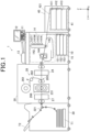
FIG. 1 is a front view showing a schematic configuration of a laminating system according to the first embodiment; -
FIG. 2 is a functional block diagram showing a control structure of the laminating system according to the first embodiment; -
FIG. 3 is a view showing an example in which a sheet is conveyed in a continuous belt shape according to the first embodiment; -
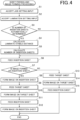
FIG. 4 is a flowchart showing the flow of a sheet feeding and image forming processing according to the first embodiment; -
FIG. 5 is a view illustrating an example of a job setting screen according to the first embodiment; -
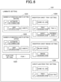
FIG. 6 is a diagram illustrating an example of a laminate setting screen according to the first embodiment; -
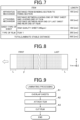
FIG. 7 is a diagram illustrating an example of calculation of a laminate stable distance according to the first embodiment; -
FIG. 8 is a view illustrating a distance between a leading end of a first sheet and a leading end of a laminate film and a distance between a rear end of a last sheet and a rear end of a laminate film according to the first embodiment; -
FIG. 9 is a flowchart showing the flow of the laminating processing according to the first embodiment; -
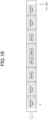
FIG. 10 is a diagram illustrating an example of an insertion sheet and a target sheet to which the laminate film is attached according to the first embodiment; -
FIG. 11 is a front view showing a schematic configuration of the laminating system according to the second embodiment; -
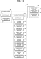
FIG. 12 is a functional block diagram showing a control structure of the laminating system according to the second embodiment; -
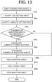
FIG. 13 is a flowchart showing the flow of the sheet feeding processing according to the second embodiment; and -
FIG. 14 is a diagram illustrating an example of the laminate setting screen according to the second embodiment. - Hereinafter, embodiments of a laminating system, a recording medium, and a laminating device of the present invention will be described with reference to the drawings. However, the scope of the invention is not limited to the disclosed embodiments.
- As illustrated in
FIGS. 1 and2 , a laminating system (hereinafter, referred to as a system 1) according to the present embodiment includes asheet feed device 40, animage forming apparatus 10, alaminating device 20, and astacker device 30. - The
sheet feed device 40 includes asheet feed section 41 and aconveying section 42, and conveys a sheet (cut sheet) from any one ofsheet feed trays 411 to 413 of thesheet feed section 41 to theimage forming apparatus 10 according to a job. - The
conveying section 42 includes aconveying path 421 that connects thesheet feed section 41 to theimage forming apparatus 10, and conveys the sheet. - The
sheet feed section 41 includessheet feed trays 411 to 413 that are housing sections for storing sheets according to predetermined sheet types and sizes. - Depending on the amount of printing, the type of sheet to be used, or the like, the
sheet feed device 40 may not be provided, and the sheet may be conveyed only from asheet feed section 15 of theimage forming apparatus 10. - The
image forming apparatus 10 forms a color image by an electrophotographic method, based on image data obtained by reading an image from a document or image data of a job received from an external device (not illustrated). Theimage forming apparatus 10 ejects the sheet on which the image is formed to the laminatingdevice 20. - As illustrated in
FIGS. 1 and2 , theimage forming apparatus 10 includes anoperation part 11, adisplay part 12, adocument reading unit 13, animage forming section 14, asheet feed section 15, an image forming controller 16 (hardware processor), astorage section 17, acommunication section 18, and an image processing section 19. - The
operation part 11 includes a touch panel formed so as to cover a display screen of thedisplay part 12, and various operation buttons such as numeric buttons and a start button. Theoperation part 11 outputs an operation signal based on a user's operation to theimage forming controller 16. - The
display part 12 includes a liquid crystal display (LCD) and displays various screens in accordance with an instruction of a display signal input from theimage forming controller 16. - The
document reading unit 13 includes an automatic document feeder (ADF), a scanner, and the like, and outputs image data obtained by reading the image of a document to theimage forming controller 16. - The
image forming section 14 forms the image on the sheet supplied by thesheet feed section 15 or thesheet feed device 40, based on the image data subjected to image processing by the image processing section 19. In the present embodiment, the sheet is a flat sheet. - The
image forming section 14 includesphotosensitive drums intermediate transfer belt 142, asecondary transfer roller 143, a fixingsection 144, and the like. - The
image forming section 14 uniformly charges thephotosensitive drum 141Y and then performs scanning exposure with a laser beam on the basis of the image data for yellow to form an electrostatic latent image. Next, theimage forming section 14 causes yellow toner to adhere to the electrostatic latent image on thephotosensitive drum 141Y to develop the images. - Since the
photosensitive drums photosensitive drum 141Y except that the handled colors are different, the description thereof will be omitted. - The
image forming section 14 sequentially transfers the toner images of the respective colors formed on thephotosensitive drums image forming section 14 forms a color toner image in which toner images of four colors are overlapped on theintermediate transfer belt 142. - The
image forming section 14 collectively transfers the color toner image on theintermediate transfer belt 142 onto the sheet by the secondary transfer roller 143 (secondary transfer). - The fixing
section 144 includes a heating roller for heating the sheet on which the color toner image is transferred and a pressure roller for pressurizing the sheet, and fixes the color toner image on the sheet by heating and pressurizing. - The
sheet feed section 15 includessheet feed trays 151 to 153, which are housing sections, and supplies sheets (cut sheet) to theimage forming section 14. Each of thesheet feed trays 151 to 153 stores sheets with a sheet type and a size predetermined for each sheet feed tray. - The
image forming controller 16 includes a central processing unit (CPU), a random access memory (RAM), a read only memory (ROM), and the like. The CPU reads various processing programs stored in the ROM and deploys the programs to the RAM. Next, the CPU integrally controls the operation of theimage forming apparatus 10 in coordination with the various programs deployed in the RAM. - When performing laminating processing on the output sheet, the
image forming controller 16 instructs thelaminating device 20 to perform predetermined laminating processing. - The
image forming controller 16 instructs thestacker device 30 to perform a predetermined sheet ejection processing. - The
image forming controller 16 causes thesheet feed section 41 of thesheet feed device 40 or thesheet feed section 15 to feed an insertion sheet at least before or after a target sheet for the laminating processing in the job. Theimage forming controller 16 functions as the controller. - The
image forming controller 16 controls theimage forming section 14. - The
image forming controller 16 calculates the number of insertion sheets to be inserted based on a stable distance (laminate stable distance) related to the laminating processing and a length of the cut sheet (sheet) in the conveying direction. Theimage forming controller 16 functions as a calculator. - The
image forming controller 16 accepts an input by the user via theoperation part 11 indicating the number of insertion sheets to be inserted. Theimage forming controller 16 functions as a receiver. - The
storage section 17 is a non-volatile storage device such as a hard disk drive (HDD) or a semiconductor memory that stores various data such as programs and image data. Thestorage section 17 stores data such as program data and various setting data so that the data can be read and written by theimage forming controller 16. - The
communication section 18 includes a communication control card such as a local area network (LAN) card, for example. Thecommunication section 18 exchanges various kinds of data with an external device (e.g., a personal computer) connected to a communication network such as a LAN or a wide area network (WAN). - The image processing section 19 performs necessary image processing on image data stored in the
storage section 17, image data obtained by reading an image from a document by thedocument reading unit 13, and image data input from an external device. Next, the image processing section 19 transmits the image data after the image processing to theimage forming section 14. The image processing includes gradation processing, halftone processing, color conversion processing, and the like. The gradation processing is processing for converting a gradation value of each pixel of the image data into a gradation value corrected such that a density characteristic of the image formed on the sheet matches a target density characteristic. The halftone processing is error diffusion processing, screen processing using a systematic dither method, or the like. The color conversion processing is a process of converting each gradation value of RGB into each gradation value of CMYK. - The
laminating device 20 is positioned between theimage forming apparatus 10 and thestacker device 30. - The
laminating device 20 includes acontroller 21, astorage section 22, a conveyingsection 23, a continuous conveyingsection 24, alaminating section 26, acutting section 27, and the like. - The
controller 21 includes a CPU, a RAM, a ROM, and the like. The CPU reads various processing programs stored in the ROM and deploys the programs to the RAM. Next, the CPU integrally controls the operation of thelaminating device 20 in coordination with the various programs deployed in the RAM. - The
controller 21 executes the laminating processing on the sheet in response to an instruction signal received from theimage forming apparatus 10. - The
storage section 22 is a nonvolatile storage device such as an HDD or a semiconductor memory that stores various data such as programs. Thestorage section 22 stores data such as program data and various setting data so that the data can be read and written by thecontroller 21. - The conveying
section 23 includes a conveyingpath 231 and a plurality of rollers. A conveyingsection 23 conveys the sheet conveyed from theimage forming apparatus 10 to a continuous conveyingsection 24, alaminating section 26, and acutting section 27 in this order, and conveys the sheet subjected to laminating processing to thestacker device 30. - As illustrated in
FIG. 1 , the continuous conveyingsection 24 is located upstream of thelaminating section 26 in the sheet conveying path. - The continuous conveying
section 24 overlaps the rear end portion of the preceding sheet on an upper portion of the front end portion of the following sheet by a predetermined overlap amount, and conveys the sheets in a continuous belt shape without intervals. As a method of overlapping the sheets, a known method can be used (e.g., seeJapanese Unexamined Patent Publication No. 2009-073668 -
FIG. 3 illustrates an example in which the sheets are conveyed in the form of a continuous belt. The arrow illustrated inFIG. 3 indicates a conveying direction of the sheets. The upper portion of the drawing ofFIG. 3 is a view of the sheet as viewed from above. The lower portion of the drawing ofFIG. 3 is a view of the sheet as viewed from a direction orthogonal to the conveying direction on the sheet. - The
laminating section 26 continuously attaches a film F to a surface (front surface) of the sheet on which an image is formed by theimage forming apparatus 10. - The
laminating section 26 includes afilm roll 261, a conveyingpath 262, abonding section 263, a fixingsection 264, and the like. - The
film roll 261 is a rolled film F including two layers of a transparent resin film layer as a base material layer and an adhesive layer. - The conveying
path 262 transports the film F from thefilm roll 261 to a nip portion of thebonding section 263. - As illustrated in
FIG. 1 , thebonding section 263 includes two rollers. Thebonding section 263 sandwiches the sheet and the film F in the nip portion formed by the two rollers, thereby adhering the adhesive layer of the film F to the surface of the sheet. Thebonding section 263 bonds the sheet and the film F. - The fixing
section 264 includes a heating roller for heating the sheet to which the film F is attached, and a pressure roller for pressing the sheet. The fixingsection 264 melts the adhesive layer of the film F by heating and fixes the film F to the sheet by pressurizing. - The cutting
section 27 includes a detectingsection 271 and acutter section 272. - The detecting
section 271 detects an edge of the sheet. The detectingsection 271 outputs a detected result to thecontroller 21. - The
cutter section 272 includes a blade (not illustrated), and a movement mechanism (not illustrated) that moves the blade in a width direction of the sheet. - Under the control of the
controller 21, thecutter section 272 inserts a blade between the overlapped end portions of the preceding sheet and the following sheet at the edge of the rear end of the preceding sheet. Next, thecutter section 272 pushes down and releases the overlapped end portion of the subsequent sheet by the blade, and moves the blade in the width direction of the sheet. Thecutter section 272 thus cuts the continuous laminate film F along the edge of the rear end of the preceding sheet. Thus, the sheets can be separated from each other. - The
stacker device 30 is located downstream of thelaminating device 20. - The
stacker device 30 includes acontroller 31, a conveyingsection 32, a large-capacity sheet ejection tray T1, and a sub-tray T2. - The large-capacity sheet ejection tray T1 includes a stage that moves up and down, and stores a large number of sheets stacked on the stage.
- The
stacker device 30 ejects the sheets to the sub-tray T2 in a state in which the sheet is exposed to the outside and is visible. - The
controller 31 includes a CPU, a RAM, a ROM, and the like. The CPU reads various processing programs stored in the ROM and deploys the programs to the RAM. Next, the CPU integrally controls the operation of thestacker device 30 in coordination with the various programs deployed in the RAM. - In response to the instruction signal received from the
image forming apparatus 10, thecontroller 31 performs a sheet ejection processing in which the laminated sheet conveyed from thelaminating device 20 is ejected to the large-capacity sheet ejection tray T1 or the sub-tray T2. - The conveying
section 32 includes a conveyingpath 321 and a plurality of rollers. Under the control of thecontroller 31, the conveyingsection 32 ejects the laminated sheet conveyed from thelaminating device 20 to the large-capacity sheet ejection tray T1 or the sub-tray T2. - Next, the operation of the
system 1 according to the present embodiment is described with reference to the flowchart inFIG. 4 . - When the
image forming apparatus 10 receives the job including a laminating processing from an external device or when the job is entered by the user via theoperation part 11, thesystem 1 executes the sheet feeding and image forming processing illustrated inFIG. 4 . - The sheet feeding and image forming processing is processing of inserting insertion sheets before and after the target sheet and forming the image only on the target sheet or on the insertion sheet and the target sheet. The target sheet is the sheet on which the job image of the job is formed and on which lamination is performed.
- In the sheet feeding and image forming processing, first, the
image forming controller 16 causes thedisplay part 12 to display ajob setting screen 121 shown inFIG. 5 . Theimage forming controller 16 accepts a user's input for setting the job (job setting) via the operation part 11 (step S1). - In the example illustrated in
FIG. 5 , theimage forming controller 16 accepts, in the sheet feed tray setting 1211, a setting to set the sheet feed tray that feeds the target sheet. - In the sheet feed tray setting 1211, the user can select the setting of the sheet feed tray for feeding the target sheet from "automatic selection" by the
image forming controller 16 or "tray designation" in which the user designates the sheet feed tray. In the example illustrated inFIG. 5 , the user selects "tray designation". - In a case where the user selects "tray designation", the
image forming controller 16 accepts designation of the sheet feed tray by the user. The sheet tray that can be specified is one of thesheet trays 411 to 413 and thesheet feed trays 151 to 153 included in thesheet feed device 40. In the example illustrated inFIG. 5 , the user has selected "tray 1". - Since the sheet feed tray stores sheets for each predetermined sheet type and size, the user can select the sheet type and the size of the sheet to be set as the target sheet by selecting the sheet feed tray.
- In the example illustrated in
FIG. 5 , theimage forming controller 16 accepts, in sheet ejection tray setting 1212, a setting for a sheet ejection tray to which the target sheet is to be ejected. - In the sheet ejection tray setting 1212, the user can select the setting of the sheet ejection tray for ejecting the target sheet from "automatic selection" by the
image forming controller 16 or "tray designation" in which the user designates the sheet ejection tray. In the example illustrated inFIG. 5 , the user selects "tray designation". - In a case where the user selects the "tray designation", the
image forming controller 16 accepts designation of the sheet ejection tray by the user. The sheet ejection tray that can be specified is the large-capacity sheet ejection tray T1 or the sub-tray T2. In the example illustrated inFIG. 5 , the user selects the large-capacity sheet ejection tray (T1). - In the example illustrated in
FIG. 5 , theimage forming controller 16 accepts a setting of the number of output copies of the job in number of copies setting 1213. In the example illustrated inFIG. 5 , the user has set the number of output copies to "10 copies". - In the example illustrated in
FIG. 5 , theimage forming controller 16 accepts, inpost-processing setting 1214, a setting for post-processing to be performed on the target sheet. - In the
post-processing setting 1214, the user can select the post-processing to be performed on the target sheet from "laminate" processing, "side stitch" processing, and "punch" processing. In the example shown inFIG. 5 , the user selects the "laminate" processing. - The user can make a setting for the post-processing, which is the "laminate" processing, the "side stitch" processing, or the "punch" processing, by pressing a
setting button 1214a. - When the user presses the
setting button 1214a of the "laminate" process, theimage forming controller 16 causes thedisplay part 12 to display alaminate setting screen 122 as shown inFIG. 6 . Theimage forming controller 16 accepts an input of the setting of the laminating processing (lamination setting) by the user via the operation part 11 (step S2). - In the example illustrated in
FIG. 6 , theimage forming controller 16 accepts the setting of the number of insertion sheets to be inserted before the target sheet in the number-of-insertion-sheets setting (before) 1221. - In the number-of-insertion-sheets setting (before) 1221, the user can select a setting for the number of insertion sheets to be inserted before the target sheet from "automatic determination" by the
image forming controller 16 or "user specification". In the example shown inFIG. 6 , the user selects "automatic determination". When the user selects "user specification", theimage forming controller 16 accepts a specification of the number of insertion sheets to be inserted before the target sheet from the user. - In the example illustrated in
FIG. 6 , in the number-of-insertion-sheets setting (after) 1222, theimage forming controller 16 accepts the setting regarding the number of insertion sheets to be inserted after the target sheet, similarly to the number-of-insertion-sheets setting (before) 1221. In the example shown inFIG. 6 , the user selects "automatic determination". - In the example shown in
FIG. 6 , theimage forming controller 16 accepts the setting of the type of the film F to be laminated on the target sheet in the film type setting 1223. In the example illustrated inFIG. 6 , the user has set the type of film F to "film 1". - In the example illustrated in
FIG. 6 , theimage forming controller 16 accepts the setting of the sheet feed tray for feeding the insertion sheet in insertionsheet tray setting 1224. - In the insertion sheet tray setting 1224, the user can select the setting of the sheet feed tray for feeding the insertion sheet from "same as job", "tray designation", or "sheet designation". The "same as job" is a setting for selecting the same sheet feed tray as the sheet feed tray for the target sheet. The "tray designation" is a setting in which the user designates the sheet feed tray. The "sheet designation" is a setting with which the user designates the sheet type of the sheet. In the example illustrated in
FIG. 6 , the user selects "tray designation". - In a case where the user selects "tray designation", the
image forming controller 16 accepts designation of the sheet feed tray by the user. The sheet feed tray that can be specified is one of thesheet feed trays 411 to 413 included in thesheet feed device 40 and thesheet feed trays 151 to 153. In the example illustrated inFIG. 6 , the user has selected "tray 2". - The sheet feed tray stores sheets according to predetermined sheet types and sizes, and thus the user can select the sheet type and the size of the sheet to be used as the insertion sheet by selecting the sheet feed tray.
- When the user selects "sheet specification", the
image forming controller 16 accepts a specification of the sheet type of the sheet from the user. - A case where the user has specified the sheet feed tray different from the sheet feed tray for the target sheet as the sheet feed tray for the insertion sheet or has specified the sheet type different from the sheet type of the target sheet as the sheet type of the insertion sheet will be described. In this case, for example, the user can reduce the cost of sheets by using, as the insertion sheet, the sheet that is less expensive than the target sheet.
- In the example illustrated in
FIG. 6 , theimage forming controller 16 accepts a setting for the image to be formed on the insertion sheet in the insertion sheet image setting 1225. - In the insertion sheet image setting 1225, the user can select the setting of the image to be formed on the insertion sheet from "blank" in which the image is not formed or "image designation" in which the user designates the image to be formed. In the example illustrated in
FIG. 6 , the user selects "blank". - When the user selects "image designation", the
image forming controller 16 accepts designation of the image to be formed on the insertion sheet by the user. The image to be formed on the insertion sheet is, for example, the image indicating the insertion sheet or a chart (patch) for image quality adjustment. The image to be formed on the insertion sheet may be the image different from the job image of the job. - When the insertion sheet is blank or the
image forming section 14 forms the image different from the job image on the insertion sheet, the user can easily distinguish between the insertion sheet and the target sheet. - In the example illustrated in
FIG. 6 , theimage forming controller 16 accepts the setting of the sheet ejection tray for ejecting the insertion sheet in the sheetejection tray setting 1226. - The user can select a setting for the sheet ejection tray to which the insertion sheet is ejected from "same as job" or "tray designation" in the sheet
ejection tray setting 1226. The "same as job" is a setting for selecting the same sheet ejection tray as the sheet ejection tray for the target sheet. The "tray designation" is a setting in which the user designates the sheet ejection tray. In the example illustrated inFIG. 6 , the user selects "tray designation". - In a case where the user selects the "tray designation", the
image forming controller 16 accepts the designation of the sheet ejection tray by the user. The sheet ejection tray that can be specified is the large-capacity sheet ejection tray T1 or the sub-tray T2. In the example illustrated inFIG. 6 , the user selects "sub-tray (T2)". - Next, the
image forming controller 16 determines whether or not the user has selected "automatic determination" in the setting of the number-of-insertion-sheets setting (before) 1221 or the number-of-insertion-sheets setting (after) 1222 in step S2 (step S3). - When the user selects "automatic determination" (step S3; YES), the
image forming controller 16 calculates a laminate stable distance that is a distance until the lamination becomes stable (step S4). In the present embodiment, the laminate stable distance for the insertion sheet to be inserted before the target sheet and the laminate stable distance for the insertion sheet to be inserted after the target sheet are the same. -
FIG. 7 shows an example of calculation of the laminate stable distance. - As shown in
FIG. 7 , theimage forming controller 16 calculates the laminate stable distance based on the apparatus mechanism and the attaching mechanism of thelaminating device 20, the sheet type of the sheet which is the insertion sheet, and the type of the film F. - The item of the apparatus mechanism is a distance from a roller of the
bonding section 263 to a roller of the fixingsection 264 in thelaminating device 20, and is 150 [mm] in the example illustrated inFIG. 7 . - The item of the attaching mechanism is a distance L between a leading end of the first sheet and a leading end of the film F illustrated in
FIG. 8 when the film F is attached to the continuously conveyed sheets. The item of the attaching mechanism is 100 [mm] in the example illustrated inFIG. 7 . The item of the attaching mechanism may be the distance L between the rear end of the last sheet and the rear end of the film F shown inFIG. 8 . - The item of the sheet type of the sheet that is the insertion sheet is a distance until the lamination corresponding to the sheet type of the insertion sheet set in the insertion sheet tray setting 1224 in step S2 becomes stable. In the example illustrated in
FIG. 7 , the sheet type of the insertion sheet is high-quality sheet (240 gsm), and the distance until the lamination becomes stable corresponding to the sheet type is 150 [mm]. - The item of the type of the film F is a distance until the lamination corresponding to the type of the film F set in the film type setting 1223 of the step S2 becomes stable. In the example shown in
FIG. 7 , the type of the film F is thefilm 1, and the distance until the lamination according to the type of the film F is stabilized is 250 [mm]. - The
image forming controller 16 calculates 650 [mm], which is the sum of the distances of the above items, as the laminate stable distance. - Next, the
image forming controller 16 calculates and determines the number of insertion sheets by the following formula (step S5). - formula: number of insertion sheets = laminate stable distance/(sheet length of insertion sheet (length in conveying direction)-overlapped amount when sheets are continuously conveyed)
- It is assumed that the laminate stable distance is 650 [mm] calculated in step S4, the sheet length of the insertion sheet is 420 [mm], and the amount of overlap is 5 [mm]. In this case, the
image forming controller 16 calculates the number of insertion sheets to be 1.6 sheets by the above formula. In this case, theimage forming controller 16 determines 2 sheets obtained by rounding up 1.6 sheets after a decimal point as the number of insertion sheets. - When the user selects "user specification" in the number-of-insertion-sheets setting (before) 1221 and the number-of-insertion-sheets setting (after) 1222 of step S2 (step S3; NO), the
image forming controller 16 shifts the present processing to step S6. - Next, the
image forming controller 16 controls thesheet feed device 40 or thesheet feed section 15 to feed the number of insertion sheets designated by the user in step S2 from the sheet feed tray set in the insertion sheet tray setting 1224 in step S2. Alternatively, theimage forming controller 16 feeds the number of insertion sheets determined in step S5 from the sheet feed tray (step S6). - Next, the
image forming controller 16 determines whether or not to form the image on the insertion sheet, that is, whether or not the image to be formed has been specified by the user in the insertion sheet image setting 1225 of step S2 (step S7). - If the image is to be formed on the insertion sheet (YES in step S7), the
image forming controller 16 controls theimage forming section 14 to form the image on the insertion sheet (step S8). The image is the image specified by the user in the insertion sheet image setting 1225 of step S2. - Next, the
image forming controller 16 controls thesheet feed device 40 or thesheet feed section 15 to feed, as target sheets, the number of sheets corresponding to the number of outputs of the job set in the number-of-copies setting 1213 in step S1 from the sheet feed tray (step S9). The sheet feed tray is the sheet feed tray set in the sheet feed tray setting 1211 of step S1. - Next, the
image forming controller 16 controls theimage forming section 14 to form the job image of the job on the target sheet (step S10). - Next, the
image forming controller 16 performs steps S6 and S8 similar to steps S11 and S12, and ends the present processing. - A case where the image is not formed on the insertion sheet (step S7; YES), that is, a case where the user selects "blank sheet" in the insertion sheet image setting 1225 of step S2 will be described. In this case, the
image forming controller 16 performs steps S9 to S11 similar to steps S13 to S15, and ends the present processing. - Next, the
image forming controller 16 ejects the insertion sheet and the target sheet subjected to the above-described sheet feeding and image forming processing, and conveys them to thelaminating device 20. - Next, the
controller 21 of thelaminating device 20 executes the laminating processing illustrated inFIG. 9 on the insertion sheet and the target sheet. - The
controller 21 controls the continuous conveyingsection 24 to overlap the insertion sheet and the target sheet and convey them in a continuous belt shape without any interval (step A1). - Next, the
controller 21 controls thelaminating section 26 to attach the film F to the insertion sheet and the target sheet (step A2). -
FIG. 10 illustrates a view in which a film F is attached on the insertion sheet and the target sheet. - In the example illustrated in
FIG. 10 , the number of insertion sheets to be inserted before and after the target sheet on which the job image has been formed is two each. - By inserting the insertion sheet before and after the target sheet in the sheet feeding and image forming processing, the target sheet can be stably laminated.
- In the example shown in
FIG. 10 , the width of the insertion sheet and the target sheet is the same as the width of the film F, but the invention is not limited thereto. The width of the film F may be smaller than the widths of the insertion sheet and the target sheet. The widths of the insertion sheet and the target sheet are the lengths in the direction orthogonal to the conveying direction indicated by the arrow inFIG. 10 . - Next, the
controller 21 controls thecutting section 27 to cut off the insertion sheet with the film F attached thereto and the target sheet one by one and convey them to the stacker device 30 (step A3), and ends the present process. - Next, the
controller 31 of thestacker device 30 performs a sheet ejection processing on the insertion sheet and the target sheet on which the lamination has been performed. - In the sheet ejection processing, the
controller 31 ejects the insertion sheet to the sheet ejection tray set in the sheet ejection tray setting 1226 in step S2 of the sheet feeding and image forming processing. - The
controller 31 ejects the target sheet to the sheet ejection tray set in the sheet ejection tray setting 1212 of step S1 of the sheet feeding and image forming processing. - Next, a second embodiment will be described.
- Hereinafter, differences from the first embodiment will be mainly described.
- As illustrated in
FIGS. 11 and12 , the laminating system (hereinafter referred to assystem 1a) according to the second embodiment includes asheet feed device 40, alaminating device 20, and astacker device 30. - The
laminating device 20 of the second embodiment further includes asheet feed section 25 having the same configuration as thesheet feed section 15 of the first embodiment, anoperation part 281 having the same configuration as theoperation part 11 of the first embodiment, adisplay part 282 having the same configuration as thedisplay part 12 of the first embodiment, and a communication section 29 having the same configuration as thecommunication section 18 of the first embodiment. - Any one of the
sheet feed trays 411 to 413 which are housing sections included in thesheet feed device 40 according to the second embodiment and thesheet feed trays 251 to 253 which are housing sections included in thesheet feed section 25 stores target sheets on which job images have been formed. - The
controller 21 of the second embodiment is a hardware processor. - The
controller 21 of the second embodiment instructs thestacker device 30 to execute a predetermined sheet ejection processing. - The
controller 21 of the second embodiment causes thesheet feed section 41 of thesheet feed device 40 or thesheet feed section 25 to feed the insertion sheet at least before or after the target sheet of the laminating processing in the job. - The
controller 21 of the second embodiment calculates the number of insertion sheets to be inserted based on the stable distance (laminate stable distance) related to the laminating processing and the length of the cut sheet (sheet) in the conveying direction. Thecontroller 21 functions as a calculator. - The
controller 21 of the second embodiment accepts an input of the number of insertion sheets to be inserted by input of theoperation part 281 by the user. Thecontroller 21 functions as a receiver. - Next, the operation of the
system 1a according to the second embodiment will be described with reference to the flowchart ofFIG. 13 . - The
system 1a executes the sheet feeding processing illustrated inFIG. 13 when thelaminating device 20 receives a job including laminating processing from the external device via the communication section 29 or when the job is input by the user via theoperation part 281. - The sheet feeding processing is a process of inserting insertion sheets before and after a target sheet to be laminated.
- In the sheet feeding processing, the
controller 21 allows thedisplay part 282 to display ajob setting screen 121 illustrated inFIG. 5 , similarly to step S1 of the sheet feeding and image forming processing described above. Thecontroller 21 accepts an input of the job setting by the user via the operation part 281 (step S1a). - A case where the user selects "automatic selection" in the sheet feed tray setting 1211 will be described. In this case, the
controller 21 selects the sheet feed tray that stores the target sheet on which the job image is formed, as the sheet feed tray that feeds the target sheet. - In a case where the user selects "tray designation", the
controller 21 accepts designation of the sheet feed tray by the user. The user designates the sheet feed tray that stores the target sheet on which the job image is formed as the sheet feed tray that feeds the target sheet. - A case will be described in which, in the
post-processing setting 1214, the user selects "laminate" processing as post-processing to be performed on the target sheet and presses asetting button 1214a. In this case, thecontroller 21 causes thedisplay part 282 to display alaminate setting screen 2821 as shown inFIG. 14 . Thecontroller 21 accepts an input of lamination setting by the user via the operation part 281 (step S2a). - In the example shown in
FIG. 14 , thecontroller 21 accepts the setting of the number of insertion sheets to be inserted before the target sheet in the number-of-insertion-sheets setting (before) 2822 in the same manner as in step S2 of the sheet feeding and image forming processing. - The
controller 21 accepts the setting of the number of insertion sheets to be inserted after the target sheet in a number-of-insertion-sheets setting (after) 2823 in the same manner as in step S2 of the sheet feeding and image forming processing described above. - The
controller 21 accepts setting of the type of film F with which laminating processing is performed on the target sheet in a film type setting 2824 in the same manner as in step S2 of the sheet feeding and image forming processing described above. - In the example illustrated in
FIG. 14 , thecontroller 21 accepts the setting of the sheet feed tray for feeding the insertion sheet in a insertionsheet tray setting 2825. - In the insertion sheet tray setting 2825, the user can select the setting of the sheet feed tray for feeding the insertion sheet from "tray designation" or "sheet designation". The "tray designation" is a setting in which the user designates the sheet feed tray. The "sheet designation" is a setting with which the user designates the sheet type of the sheet. In the example illustrated in
FIG. 14 , the user selects "tray designation". - In a case where the user selects "tray designation", the
controller 21 accepts designation of the sheet feed tray by the user. The sheet feed tray that can be specified is the sheet feed tray that does not contain the target sheet among thesheet feed trays 411 to 413 and thesheet feed trays 251 to 253 included in thesheet feed device 40. In the example illustrated inFIG. 14 , the user has selected "tray 2". - The sheet feed tray stores sheets according to predetermined sheet types and sizes, and thus the user can select the sheet type and the size of the sheet to be used as the insertion sheet by selecting the sheet feed tray.
- In a case where the user selects "sheet designation", the
controller 21 accepts the designation of the sheet type of the sheet by the user. - In the example shown in
FIG. 14 , thecontroller 21 accepts the setting of the sheet ejection tray for ejecting the insertion sheet in the sheet ejection tray setting 2826 in the same manner as in step S2 of the sheet feeding and image forming processing. - Next, the
controller 21 performs steps S3a to S8a similar to steps S3 to S6, S9, and S11 of the above-described sheet feeding and image forming processing and ends the present processing. - The laminating method of the first embodiment and the second embodiment is a hot laminating method of melting and fixing the adhesive layer of the film F by the fixing
section 264, but is not limited thereto. The lamination method may be a cold laminating method in which fixing is performed by the adhesive layer of the film F which can be adhered at room temperature without heating in thefixing section 264. - As described above, the laminating system (system 1) according to the present embodiment includes the sheet feed sections (
sheet feed section 41,sheet feed section 15, and sheet feed section 25) that feed cut sheets (sheets), the continuous conveyingsection 24 that conveys a plurality of cut sheets fed by the sheet feed sections without an interval between cut sheets, thelaminating section 26 that executes the laminating processing of attaching the laminate film (film F) to the plurality of cut sheets conveyed by the continuous conveyingsection 24, and the controller (image forming controller 16 and controller 21) that causes the sheet feed sections to feed the insertion sheet at least before or after the target sheet on which the laminating processing is performed. - Therefore, since insertion sheets that are waste sheets can be automatically inserted before and after the sheet to be subjected to the laminating processing, the laminating processing can be efficiently performed with high quality.
- The laminating system according to the present embodiment includes the
image forming section 14 that forms the image on the cut sheet fed by the sheet feed section, and theimage forming controller 16 that controls theimage forming section 14. - Therefore, it is possible to form the image on only the target sheet or on the insertion sheet and the target sheet.
- In the laminating system according to the present embodiment, the
image forming controller 16 causes theimage forming section 14 not to form the image on the insertion sheet but to form the image on the target sheet. - Therefore, since the insertion sheet can be set as the blank sheet and the job image can be formed on the target sheet, the user can easily distinguish between the insertion sheet and the target sheet.
- In the laminating system according to the present embodiment, the
image forming controller 16 causes theimage forming section 14 to form the image different from the image to be formed on the target sheet on the insertion sheet. - Therefore, the user can easily distinguish between the insertion sheet and the target sheet by the formed image.
- In the laminating system according to the present embodiment, the sheet feed section includes the plurality of housing sections (
sheet feed trays 411 to 413,sheet feed trays 151 to 153, andsheet feed trays 251 to 253) for storing the cut sheets, and the controller causes the insertion sheet to be fed from the housing section different from the housing section that feeds the target sheet. - Therefore, for example, if the sheet feed tray different from the sheet feed tray for the target sheet is selected as the sheet feed tray for the insertion sheet and the sheet that is less expensive than the target sheet is used as the sheet tray for the insertion sheet, the cost of the sheet can be reduced.
- In the laminating system according to the present embodiment, the width of the insertion sheet is equal to or greater than the width of the laminate film.
- Therefore, it is possible to prevent the adhesive layer of the laminate film from adhering to the roller or the conveying path in the
laminating device 20 and causing conveying trouble. - In the laminating system according to the present embodiment, the sheet type of the insertion sheet is the same as the sheet type of the target sheet.
- Therefore, by selecting the same sheet feed tray as the sheet feed tray of the target sheet as the sheet feed tray for feeding the insertion sheet, it is possible to save the user the trouble of designating the sheet feed tray of the insertion sheet or designating the sheet type of the insertion sheet.
- In the laminating system according to the present embodiment, the sheet type of the insertion sheet is different from the sheet type of the target sheet.
- Therefore, for example, if the sheet that is less expensive than the target sheet is used as the insertion sheet, the cost of the sheet can be reduced.
- The laminating system according to the present embodiment includes the calculator (the
image forming controller 16 and the controller 21) that calculates the number of insertion sheets to be inserted based on the stable distance related to the laminating processing and the length of the cut sheet in the conveying direction, and the controller causes the number of insertion sheets calculated by the calculator to be fed. - Accordingly, as many insertion sheets as the number of sheets for which lamination is stable can be inserted, and thus stable lamination can be performed on the target sheet.
- In the laminating system according to the present embodiment, the calculator calculates the stable distance based on at least one of the type of the laminate film and the sheet type of the cut sheet.
- Therefore, a more appropriate laminate stable distance can be calculated.
- The laminating system according to the present embodiment includes the receiver (the
image forming controller 16 and the controller 21) that accepts the user's input of the number of insertion sheets to be inserted, and the controller causes the insertion sheets to be fed by the number input on the receiver. - Therefore, the user can insert the desired number of sheets of the insertion sheet.
- In the laminating system according to the present embodiment, the continuous conveying
section 24 conveys the cut sheet with the rear end portion of the preceding cut sheet overlapping the upper portion of the front end portion of the following cut sheet by a predetermined amount. - Therefore, it is possible to prevent the adhesive layer of the laminate film from adhering to the roller or the conveying path in the
laminating device 20 and causing conveying trouble. - The laminating system according to the present embodiment includes the fixing
section 264 that performs thermocompression bonding on the cut sheet to which the laminate film is attached. - Therefore, the laminate film can be attached and fixed to the sheet by the hot laminating method.
- In the laminating system according to the present embodiment, the laminate film includes the base material layer and the adhesive layer laminated on one surface of the base material layer.
- Therefore, the laminate film can be attached and fixed to the sheet also by the cold laminating method.
- The laminating system according to the present embodiment includes the cutting
section 27 that cuts the laminate film along the edge of the rear end of the preceding cut sheet or the edge of the front end of the following cut sheet subjected to the laminating processing by thelaminating section 26. - Therefore, the sheets on which the laminating processing is performed can be cut off one by one.
- Although specific description has been given above on the basis of the embodiment according to the present invention, the present invention is not limited to the above-described embodiment, and modifications can be made without departing from the spirit and scope of the present invention.
- For example, although the continuous conveying
section 24 causes the rear end portion of the preceding sheet to overlap the upper portion of the front end portion of the following sheet by the predetermined overlap amount in the embodiment described above, there is no limitation thereto. The continuous conveyingsection 24 may perform continuous conveying such that the overlap amount is 0, that is, the rear end edge of the preceding sheet and the front end edge of the following sheet are in contact with each other. The continuous conveyingsection 24 may overlap the rear end portion of the preceding sheet with the lower portion of the front end portion of the following sheet by the predetermined overlap amount. - In a case where the continuous conveying
section 24 overlaps the rear end portion of the preceding sheet on the lower portion of the front end portion of the following sheet by the predetermined overlap amount, the cuttingsection 27 cuts the film F along the front end edge of the following sheet. - In the above-described embodiment, the sheet feeding and image forming processing or the sheet feeding processing is executed, and the insertion sheets are inserted before and after the target sheet. The sheet feeding and image forming processing or the sheet feeding processing of the above-described embodiment may be executed, and the insertion sheet may be inserted in only one between before or after the target sheet.
- In addition, the detailed configuration of each device constituting the laminating system and the detailed operation of each device can be appropriately changed without departing from the scope of the present invention.
- Although some embodiments of the present invention have been described, the scope of the present invention is not limited to the above-described embodiments, and includes the scope of the invention described in the claims and its equivalents.
- Although embodiments of the present invention have been described and illustrated in detail, the disclosed embodiments are made for purposes of illustration and example only and not limitation. The scope of the present invention should be interpreted by terms of the appended claims.
Claims (17)
- A laminating system (1) comprising:a sheet feed section (15, 25, 41) that feeds cut sheets;a continuous conveying section (24) that conveys the plurality of cut sheets fed by the sheet feed section without any interval between the cut sheets;a laminating section (26) which executes laminating processing of attaching a laminate film to the plurality of cut sheets conveyed by the continuous conveying section; anda controller (16, 21) that causes the sheet feed section to feed an insertion sheet at least before or after a target sheet on which the laminating processing is performed.
- The laminating system according to claim 1, further comprising,an image forming section (14) that forms an image on the cut sheet fed by the sheet feed section; andan image forming controller (16) controls the image forming section.
- The laminating system according to claim 2, wherein the image forming controller causes the image forming section not to form the image on the insertion sheet but to form the image on the target sheet.
- The laminating system according to claim 2, wherein the image forming controller causes the image forming section to form, on the insertion sheet, the image different from the image to be formed on the target sheet.
- The laminating system according to any one of claims 1 to 4,wherein the sheet feed section includes a plurality of housing sections (151-153, 251-253, 411-413) that store the cut sheet, andwherein the controller causes the insertion sheet to be fed from the housing section different from the housing section that feeds the target sheet.
- The laminating system according to any one of claims 1 to 4, wherein a width of the insertion sheet is equal to or more than a width of the laminate film.
- The laminating system according to any one of claims 1 to 4, wherein a sheet type of the insertion sheet is the same as a sheet type of the target sheet.
- The laminating system according to any one of claims 1 to 4, wherein a sheet type of the insertion sheet is different from a sheet type of the target sheet.
- The laminating system according to any one of claims 1 to 4, further comprising a calculator (16, 21) that calculates the number of sheets of the insertion sheet to be inserted based on a stable distance related to the laminating processing and a length of the cut sheet in a conveying direction,
wherein the controller feeds the insertion sheet according to the number of sheets calculated by the calculator - The laminating system according to claim 9, wherein the calculator calculates the stable distance based on at least one of a type of the laminate film and a sheet type of the cut sheet.
- The laminating system according to any one of claims 1 to 4, further comprising a receiver (16, 21) that accepts from a user an input of the number of sheets of the insertion sheet to be inserted, wherein the controller feeds the insertion sheet according to the number of sheets input on the receiver.
- The laminating system according to any one of claims 1 to 4, wherein the continuous conveying section conveys the cut sheet in a state where a rear end portion of a preceding cut sheet is overlapped by a predetermined amount on an upper portion of a front end portion of a following cut sheet.
- The laminating system according to any one of claims 1 to 4, further comprising a fixing section (264) that thermally presses the cut sheet to which the laminate film is attached.
- The laminating system according to any one of claims 1 to 4, wherein the laminate film includes a base material layer and an adhesive layer layered on one surface of the base material layer.
- The laminating system according to any one of claims 1 to 4, further comprising a cutting section (27) that cuts the laminate film along an edge of a rear end of the preceding cut sheet or an edge of a front end of the following cut sheet subjected to the laminating processing by the laminating section.
- A program causing a computer to function as,a sheet feed section (15, 25, 41) that feeds cut sheets,a continuous conveying section (24) that conveys the plurality of cut sheets fed by the sheet feed section without any interval between the cut sheets,a laminating section (26) which executes laminating processing of attaching a laminate film to the plurality of cut sheets conveyed by the continuous conveying section, anda controller (16, 21) that causes the sheet feed section to feed an insertion sheet at least before or after a target sheet on which the laminating processing is performed.
- A laminating device (20) comprising:a sheet feed section (25) that feeds cut sheets;a continuous conveying section (24) that conveys the plurality of cut sheets fed by the sheet feed section without any interval between the cut sheets;a laminating section (26) which executes laminating processing of attaching a laminate film to the plurality of cut sheets conveyed by the continuous conveying section; anda controller (21) that causes the sheet feed section to feed an insertion sheet at least before or after a target sheet on which the laminating processing is performed.
Applications Claiming Priority (1)
| Application Number | Priority Date | Filing Date | Title |
|---|---|---|---|
| JP2022092357A JP2023179198A (en) | 2022-06-07 | 2022-06-07 | Laminating system, program and laminating equipment |
Publications (1)
| Publication Number | Publication Date |
|---|---|
| EP4289619A1 true EP4289619A1 (en) | 2023-12-13 |
Family
ID=86657116
Family Applications (1)
| Application Number | Title | Priority Date | Filing Date |
|---|---|---|---|
| EP23176728.6A Pending EP4289619A1 (en) | 2022-06-07 | 2023-06-01 | Laminating system, program, and laminating device |
Country Status (4)
| Country | Link |
|---|---|
| US (1) | US20230391061A1 (en) |
| EP (1) | EP4289619A1 (en) |
| JP (1) | JP2023179198A (en) |
| CN (1) | CN117183554A (en) |
Families Citing this family (1)
| Publication number | Priority date | Publication date | Assignee | Title |
|---|---|---|---|---|
| JP2025119717A (en) * | 2024-02-02 | 2025-08-15 | コニカミノルタ株式会社 | Lamination systems and programs |
Citations (7)
| Publication number | Priority date | Publication date | Assignee | Title |
|---|---|---|---|---|
| GB2228255A (en) * | 1989-01-21 | 1990-08-22 | Langston Machine | Sheet and web feeding |
| JPH0623689A (en) | 1992-07-09 | 1994-02-01 | Nippon Chemicon Corp | Cutter structure for laminate paper sheet |
| US5639335A (en) * | 1992-03-24 | 1997-06-17 | Ulrich Steinemann Ag | Cutting process, device and installation for producing laminates |
| JP2000062124A (en) | 1998-08-19 | 2000-02-29 | Mck:Kk | Film coating method and laminator |
| JP2009073668A (en) | 2007-08-31 | 2009-04-09 | Komori Corp | Overlay device |
| US20110094684A1 (en) * | 2007-08-31 | 2011-04-28 | Shin Ohsawa | Sheet-fed offset printing press |
| US20200009848A1 (en) * | 2016-11-03 | 2020-01-09 | Koenig & Bauer Ag | Laminating machine |
Family Cites Families (3)
| Publication number | Priority date | Publication date | Assignee | Title |
|---|---|---|---|---|
| JP2004331370A (en) * | 2003-05-12 | 2004-11-25 | Konica Minolta Business Technologies Inc | Post-processing device and image forming system equipped with it |
| JP2006251962A (en) * | 2005-03-09 | 2006-09-21 | Konica Minolta Medical & Graphic Inc | Image editing apparatus, image forming system and image editing program |
| JP4461168B2 (en) * | 2007-12-04 | 2010-05-12 | シャープ株式会社 | Image forming apparatus, image forming system, program, and recording medium |
-
2022
- 2022-06-07 JP JP2022092357A patent/JP2023179198A/en active Pending
-
2023
- 2023-06-01 EP EP23176728.6A patent/EP4289619A1/en active Pending
- 2023-06-01 CN CN202310640357.5A patent/CN117183554A/en active Pending
- 2023-06-07 US US18/330,618 patent/US20230391061A1/en active Pending
Patent Citations (7)
| Publication number | Priority date | Publication date | Assignee | Title |
|---|---|---|---|---|
| GB2228255A (en) * | 1989-01-21 | 1990-08-22 | Langston Machine | Sheet and web feeding |
| US5639335A (en) * | 1992-03-24 | 1997-06-17 | Ulrich Steinemann Ag | Cutting process, device and installation for producing laminates |
| JPH0623689A (en) | 1992-07-09 | 1994-02-01 | Nippon Chemicon Corp | Cutter structure for laminate paper sheet |
| JP2000062124A (en) | 1998-08-19 | 2000-02-29 | Mck:Kk | Film coating method and laminator |
| JP2009073668A (en) | 2007-08-31 | 2009-04-09 | Komori Corp | Overlay device |
| US20110094684A1 (en) * | 2007-08-31 | 2011-04-28 | Shin Ohsawa | Sheet-fed offset printing press |
| US20200009848A1 (en) * | 2016-11-03 | 2020-01-09 | Koenig & Bauer Ag | Laminating machine |
Also Published As
| Publication number | Publication date |
|---|---|
| JP2023179198A (en) | 2023-12-19 |
| US20230391061A1 (en) | 2023-12-07 |
| CN117183554A (en) | 2023-12-08 |
Similar Documents
| Publication | Publication Date | Title |
|---|---|---|
| US20230391061A1 (en) | Laminating system, recording medium, and laminating device | |
| US20240083158A1 (en) | Laminating system, laminating apparatus, and recording medium | |
| US11868069B2 (en) | Image forming system and storage medium | |
| JP5999145B2 (en) | Post-processing apparatus and image forming apparatus | |
| JP2011253073A (en) | Image forming apparatus | |
| US20250249675A1 (en) | Laminating system and storage medium | |
| US20250055947A1 (en) | Image processing system | |
| US12623448B2 (en) | Laminating system, image forming apparatus, and recording medium | |
| US12246523B2 (en) | Processing method, laminator system, laminator, post-processing apparatus, and recording medium | |
| US20250381770A1 (en) | Laminating system and storage medium | |
| JP2025187546A (en) | Laminating System | |
| JP2023179049A (en) | Laminator system, laminator, post-processing equipment, processing method and program | |
| JP7694618B2 (en) | Imaging system and method | |
| US20260116063A1 (en) | Laminating device, image forming system, and storage medium | |
| JP7287200B2 (en) | image forming device | |
| JP2026083768A (en) | Laminating systems and programs | |
| US20230364902A1 (en) | Laminating apparatus, image forming system, storage medium, and control device | |
| JP2024179879A (en) | Lamination system, lamination method and program | |
| US11627234B2 (en) | Post-processing device, image forming device, adjustment method for post-processing device, and recording medium | |
| JP2025070088A (en) | Lamination device, program and lamination system | |
| KR20130029722A (en) | Data processing apparatus and data file | |
| JP2026054097A (en) | Laminating system, control method and program | |
| JP6822022B2 (en) | Image forming device | |
| JP2025086670A (en) | Lamination systems and programs | |
| JP2025023367A (en) | Image forming system, post-processing control method and program |
Legal Events
| Date | Code | Title | Description |
|---|---|---|---|
| PUAI | Public reference made under article 153(3) epc to a published international application that has entered the european phase |
Free format text: ORIGINAL CODE: 0009012 |
|
| STAA | Information on the status of an ep patent application or granted ep patent |
Free format text: STATUS: THE APPLICATION HAS BEEN PUBLISHED |
|
| AK | Designated contracting states |
Kind code of ref document: A1 Designated state(s): AL AT BE BG CH CY CZ DE DK EE ES FI FR GB GR HR HU IE IS IT LI LT LU LV MC ME MK MT NL NO PL PT RO RS SE SI SK SM TR |
|
| P01 | Opt-out of the competence of the unified patent court (upc) registered |
Effective date: 20240112 |
|
| STAA | Information on the status of an ep patent application or granted ep patent |
Free format text: STATUS: REQUEST FOR EXAMINATION WAS MADE |
|
| 17P | Request for examination filed |
Effective date: 20240605 |
|
| RBV | Designated contracting states (corrected) |
Designated state(s): AL AT BE BG CH CY CZ DE DK EE ES FI FR GB GR HR HU IE IS IT LI LT LU LV MC ME MK MT NL NO PL PT RO RS SE SI SK SM TR |
|
| STAA | Information on the status of an ep patent application or granted ep patent |
Free format text: STATUS: EXAMINATION IS IN PROGRESS |
|
| 17Q | First examination report despatched |
Effective date: 20241204 |
|
| GRAP | Despatch of communication of intention to grant a patent |
Free format text: ORIGINAL CODE: EPIDOSNIGR1 |
|
| STAA | Information on the status of an ep patent application or granted ep patent |
Free format text: STATUS: GRANT OF PATENT IS INTENDED |
|
| INTG | Intention to grant announced |
Effective date: 20260128 |
|
| GRAS | Grant fee paid |
Free format text: ORIGINAL CODE: EPIDOSNIGR3 |
|
| GRAA | (expected) grant |
Free format text: ORIGINAL CODE: 0009210 |
|
| STAA | Information on the status of an ep patent application or granted ep patent |
Free format text: STATUS: THE PATENT HAS BEEN GRANTED |