EP4289604B1 - Verfahren zur herstellung von verbundwerkstoff - Google Patents
Verfahren zur herstellung von verbundwerkstoff Download PDFInfo
- Publication number
- EP4289604B1 EP4289604B1 EP22382545.6A EP22382545A EP4289604B1 EP 4289604 B1 EP4289604 B1 EP 4289604B1 EP 22382545 A EP22382545 A EP 22382545A EP 4289604 B1 EP4289604 B1 EP 4289604B1
- Authority
- EP
- European Patent Office
- Prior art keywords
- mold
- partially cured
- parts
- ensemble
- vacuum
- Prior art date
- Legal status (The legal status is an assumption and is not a legal conclusion. Google has not performed a legal analysis and makes no representation as to the accuracy of the status listed.)
- Active
Links
Images


Classifications
-
- B—PERFORMING OPERATIONS; TRANSPORTING
- B29—WORKING OF PLASTICS; WORKING OF SUBSTANCES IN A PLASTIC STATE IN GENERAL
- B29C—SHAPING OR JOINING OF PLASTICS; SHAPING OF MATERIAL IN A PLASTIC STATE, NOT OTHERWISE PROVIDED FOR; AFTER-TREATMENT OF THE SHAPED PRODUCTS, e.g. REPAIRING
- B29C70/00—Shaping composites, i.e. plastics material comprising reinforcements, fillers or preformed parts, e.g. inserts
- B29C70/04—Shaping composites, i.e. plastics material comprising reinforcements, fillers or preformed parts, e.g. inserts comprising reinforcements only, e.g. self-reinforcing plastics
- B29C70/28—Shaping operations therefor
- B29C70/40—Shaping or impregnating by compression not applied
- B29C70/42—Shaping or impregnating by compression not applied for producing articles of definite length, i.e. discrete articles
- B29C70/44—Shaping or impregnating by compression not applied for producing articles of definite length, i.e. discrete articles using isostatic pressure, e.g. pressure difference-moulding, vacuum bag-moulding, autoclave-moulding or expanding rubber-moulding
-
- B—PERFORMING OPERATIONS; TRANSPORTING
- B64—AIRCRAFT; AVIATION; COSMONAUTICS
- B64F—GROUND OR AIRCRAFT-CARRIER-DECK INSTALLATIONS SPECIALLY ADAPTED FOR USE IN CONNECTION WITH AIRCRAFT; DESIGNING, MANUFACTURING, ASSEMBLING, CLEANING, MAINTAINING OR REPAIRING AIRCRAFT, NOT OTHERWISE PROVIDED FOR; HANDLING, TRANSPORTING, TESTING OR INSPECTING AIRCRAFT COMPONENTS, NOT OTHERWISE PROVIDED FOR
- B64F5/00—Designing, manufacturing, assembling, cleaning, maintaining or repairing aircraft, not otherwise provided for; Handling, transporting, testing or inspecting aircraft components, not otherwise provided for
- B64F5/10—Manufacturing or assembling aircraft, e.g. jigs therefor
-
- B—PERFORMING OPERATIONS; TRANSPORTING
- B29—WORKING OF PLASTICS; WORKING OF SUBSTANCES IN A PLASTIC STATE IN GENERAL
- B29C—SHAPING OR JOINING OF PLASTICS; SHAPING OF MATERIAL IN A PLASTIC STATE, NOT OTHERWISE PROVIDED FOR; AFTER-TREATMENT OF THE SHAPED PRODUCTS, e.g. REPAIRING
- B29C65/00—Joining or sealing of preformed parts, e.g. welding of plastics materials; Apparatus therefor
- B29C65/02—Joining or sealing of preformed parts, e.g. welding of plastics materials; Apparatus therefor by heating, with or without pressure
-
- B—PERFORMING OPERATIONS; TRANSPORTING
- B29—WORKING OF PLASTICS; WORKING OF SUBSTANCES IN A PLASTIC STATE IN GENERAL
- B29C—SHAPING OR JOINING OF PLASTICS; SHAPING OF MATERIAL IN A PLASTIC STATE, NOT OTHERWISE PROVIDED FOR; AFTER-TREATMENT OF THE SHAPED PRODUCTS, e.g. REPAIRING
- B29C65/00—Joining or sealing of preformed parts, e.g. welding of plastics materials; Apparatus therefor
- B29C65/02—Joining or sealing of preformed parts, e.g. welding of plastics materials; Apparatus therefor by heating, with or without pressure
- B29C65/18—Joining or sealing of preformed parts, e.g. welding of plastics materials; Apparatus therefor by heating, with or without pressure using heated tools
-
- B—PERFORMING OPERATIONS; TRANSPORTING
- B29—WORKING OF PLASTICS; WORKING OF SUBSTANCES IN A PLASTIC STATE IN GENERAL
- B29C—SHAPING OR JOINING OF PLASTICS; SHAPING OF MATERIAL IN A PLASTIC STATE, NOT OTHERWISE PROVIDED FOR; AFTER-TREATMENT OF THE SHAPED PRODUCTS, e.g. REPAIRING
- B29C66/00—General aspects of processes or apparatus for joining preformed parts
- B29C66/001—Joining in special atmospheres
- B29C66/0012—Joining in special atmospheres characterised by the type of environment
- B29C66/0014—Gaseous environments
- B29C66/00145—Vacuum, e.g. partial vacuum
-
- B—PERFORMING OPERATIONS; TRANSPORTING
- B29—WORKING OF PLASTICS; WORKING OF SUBSTANCES IN A PLASTIC STATE IN GENERAL
- B29C—SHAPING OR JOINING OF PLASTICS; SHAPING OF MATERIAL IN A PLASTIC STATE, NOT OTHERWISE PROVIDED FOR; AFTER-TREATMENT OF THE SHAPED PRODUCTS, e.g. REPAIRING
- B29C66/00—General aspects of processes or apparatus for joining preformed parts
- B29C66/01—General aspects dealing with the joint area or with the area to be joined
- B29C66/05—Particular design of joint configurations
- B29C66/10—Particular design of joint configurations particular design of the joint cross-sections
- B29C66/11—Joint cross-sections comprising a single joint-segment, i.e. one of the parts to be joined comprising a single joint-segment in the joint cross-section
- B29C66/112—Single lapped joints
-
- B—PERFORMING OPERATIONS; TRANSPORTING
- B29—WORKING OF PLASTICS; WORKING OF SUBSTANCES IN A PLASTIC STATE IN GENERAL
- B29C—SHAPING OR JOINING OF PLASTICS; SHAPING OF MATERIAL IN A PLASTIC STATE, NOT OTHERWISE PROVIDED FOR; AFTER-TREATMENT OF THE SHAPED PRODUCTS, e.g. REPAIRING
- B29C66/00—General aspects of processes or apparatus for joining preformed parts
- B29C66/01—General aspects dealing with the joint area or with the area to be joined
- B29C66/05—Particular design of joint configurations
- B29C66/10—Particular design of joint configurations particular design of the joint cross-sections
- B29C66/13—Single flanged joints; Fin-type joints; Single hem joints; Edge joints; Interpenetrating fingered joints; Other specific particular designs of joint cross-sections not provided for in groups B29C66/11 - B29C66/12
- B29C66/131—Single flanged joints, i.e. one of the parts to be joined being rigid and flanged in the joint area
-
- B—PERFORMING OPERATIONS; TRANSPORTING
- B29—WORKING OF PLASTICS; WORKING OF SUBSTANCES IN A PLASTIC STATE IN GENERAL
- B29C—SHAPING OR JOINING OF PLASTICS; SHAPING OF MATERIAL IN A PLASTIC STATE, NOT OTHERWISE PROVIDED FOR; AFTER-TREATMENT OF THE SHAPED PRODUCTS, e.g. REPAIRING
- B29C66/00—General aspects of processes or apparatus for joining preformed parts
- B29C66/50—General aspects of joining tubular articles; General aspects of joining long products, i.e. bars or profiled elements; General aspects of joining single elements to tubular articles, hollow articles or bars; General aspects of joining several hollow-preforms to form hollow or tubular articles
- B29C66/51—Joining tubular articles, profiled elements or bars; Joining single elements to tubular articles, hollow articles or bars; Joining several hollow-preforms to form hollow or tubular articles
- B29C66/52—Joining tubular articles, bars or profiled elements
- B29C66/524—Joining profiled elements
-
- B—PERFORMING OPERATIONS; TRANSPORTING
- B29—WORKING OF PLASTICS; WORKING OF SUBSTANCES IN A PLASTIC STATE IN GENERAL
- B29C—SHAPING OR JOINING OF PLASTICS; SHAPING OF MATERIAL IN A PLASTIC STATE, NOT OTHERWISE PROVIDED FOR; AFTER-TREATMENT OF THE SHAPED PRODUCTS, e.g. REPAIRING
- B29C66/00—General aspects of processes or apparatus for joining preformed parts
- B29C66/50—General aspects of joining tubular articles; General aspects of joining long products, i.e. bars or profiled elements; General aspects of joining single elements to tubular articles, hollow articles or bars; General aspects of joining several hollow-preforms to form hollow or tubular articles
- B29C66/51—Joining tubular articles, profiled elements or bars; Joining single elements to tubular articles, hollow articles or bars; Joining several hollow-preforms to form hollow or tubular articles
- B29C66/53—Joining single elements to tubular articles, hollow articles or bars
- B29C66/532—Joining single elements to the wall of tubular articles, hollow articles or bars
-
- B—PERFORMING OPERATIONS; TRANSPORTING
- B29—WORKING OF PLASTICS; WORKING OF SUBSTANCES IN A PLASTIC STATE IN GENERAL
- B29C—SHAPING OR JOINING OF PLASTICS; SHAPING OF MATERIAL IN A PLASTIC STATE, NOT OTHERWISE PROVIDED FOR; AFTER-TREATMENT OF THE SHAPED PRODUCTS, e.g. REPAIRING
- B29C66/00—General aspects of processes or apparatus for joining preformed parts
- B29C66/50—General aspects of joining tubular articles; General aspects of joining long products, i.e. bars or profiled elements; General aspects of joining single elements to tubular articles, hollow articles or bars; General aspects of joining several hollow-preforms to form hollow or tubular articles
- B29C66/61—Joining from or joining on the inside
-
- B—PERFORMING OPERATIONS; TRANSPORTING
- B29—WORKING OF PLASTICS; WORKING OF SUBSTANCES IN A PLASTIC STATE IN GENERAL
- B29C—SHAPING OR JOINING OF PLASTICS; SHAPING OF MATERIAL IN A PLASTIC STATE, NOT OTHERWISE PROVIDED FOR; AFTER-TREATMENT OF THE SHAPED PRODUCTS, e.g. REPAIRING
- B29C66/00—General aspects of processes or apparatus for joining preformed parts
- B29C66/70—General aspects of processes or apparatus for joining preformed parts characterised by the composition, physical properties or the structure of the material of the parts to be joined; Joining with non-plastics material
- B29C66/72—General aspects of processes or apparatus for joining preformed parts characterised by the composition, physical properties or the structure of the material of the parts to be joined; Joining with non-plastics material characterised by the structure of the material of the parts to be joined
- B29C66/721—Fibre-reinforced materials
-
- B—PERFORMING OPERATIONS; TRANSPORTING
- B29—WORKING OF PLASTICS; WORKING OF SUBSTANCES IN A PLASTIC STATE IN GENERAL
- B29C—SHAPING OR JOINING OF PLASTICS; SHAPING OF MATERIAL IN A PLASTIC STATE, NOT OTHERWISE PROVIDED FOR; AFTER-TREATMENT OF THE SHAPED PRODUCTS, e.g. REPAIRING
- B29C66/00—General aspects of processes or apparatus for joining preformed parts
- B29C66/70—General aspects of processes or apparatus for joining preformed parts characterised by the composition, physical properties or the structure of the material of the parts to be joined; Joining with non-plastics material
- B29C66/73—General aspects of processes or apparatus for joining preformed parts characterised by the composition, physical properties or the structure of the material of the parts to be joined; Joining with non-plastics material characterised by the intensive physical properties of the material of the parts to be joined, by the optical properties of the material of the parts to be joined, by the extensive physical properties of the parts to be joined, by the state of the material of the parts to be joined or by the material of the parts to be joined being a thermoplastic or a thermoset
- B29C66/737—General aspects of processes or apparatus for joining preformed parts characterised by the composition, physical properties or the structure of the material of the parts to be joined; Joining with non-plastics material characterised by the intensive physical properties of the material of the parts to be joined, by the optical properties of the material of the parts to be joined, by the extensive physical properties of the parts to be joined, by the state of the material of the parts to be joined or by the material of the parts to be joined being a thermoplastic or a thermoset characterised by the state of the material of the parts to be joined
- B29C66/7375—General aspects of processes or apparatus for joining preformed parts characterised by the composition, physical properties or the structure of the material of the parts to be joined; Joining with non-plastics material characterised by the intensive physical properties of the material of the parts to be joined, by the optical properties of the material of the parts to be joined, by the extensive physical properties of the parts to be joined, by the state of the material of the parts to be joined or by the material of the parts to be joined being a thermoplastic or a thermoset characterised by the state of the material of the parts to be joined uncured, partially cured or fully cured
- B29C66/73753—General aspects of processes or apparatus for joining preformed parts characterised by the composition, physical properties or the structure of the material of the parts to be joined; Joining with non-plastics material characterised by the intensive physical properties of the material of the parts to be joined, by the optical properties of the material of the parts to be joined, by the extensive physical properties of the parts to be joined, by the state of the material of the parts to be joined or by the material of the parts to be joined being a thermoplastic or a thermoset characterised by the state of the material of the parts to be joined uncured, partially cured or fully cured the to-be-joined area of at least one of the parts to be joined being partially cured, i.e. partially cross-linked, partially vulcanized
- B29C66/73754—General aspects of processes or apparatus for joining preformed parts characterised by the composition, physical properties or the structure of the material of the parts to be joined; Joining with non-plastics material characterised by the intensive physical properties of the material of the parts to be joined, by the optical properties of the material of the parts to be joined, by the extensive physical properties of the parts to be joined, by the state of the material of the parts to be joined or by the material of the parts to be joined being a thermoplastic or a thermoset characterised by the state of the material of the parts to be joined uncured, partially cured or fully cured the to-be-joined area of at least one of the parts to be joined being partially cured, i.e. partially cross-linked, partially vulcanized the to-be-joined areas of both parts to be joined being partially cured
-
- B—PERFORMING OPERATIONS; TRANSPORTING
- B29—WORKING OF PLASTICS; WORKING OF SUBSTANCES IN A PLASTIC STATE IN GENERAL
- B29C—SHAPING OR JOINING OF PLASTICS; SHAPING OF MATERIAL IN A PLASTIC STATE, NOT OTHERWISE PROVIDED FOR; AFTER-TREATMENT OF THE SHAPED PRODUCTS, e.g. REPAIRING
- B29C66/00—General aspects of processes or apparatus for joining preformed parts
- B29C66/80—General aspects of machine operations or constructions and parts thereof
- B29C66/81—General aspects of the pressing elements, i.e. the elements applying pressure on the parts to be joined in the area to be joined, e.g. the welding jaws or clamps
- B29C66/814—General aspects of the pressing elements, i.e. the elements applying pressure on the parts to be joined in the area to be joined, e.g. the welding jaws or clamps characterised by the design of the pressing elements, e.g. of the welding jaws or clamps
- B29C66/8141—General aspects of the pressing elements, i.e. the elements applying pressure on the parts to be joined in the area to be joined, e.g. the welding jaws or clamps characterised by the design of the pressing elements, e.g. of the welding jaws or clamps characterised by the surface geometry of the part of the pressing elements, e.g. welding jaws or clamps, coming into contact with the parts to be joined
- B29C66/81431—General aspects of the pressing elements, i.e. the elements applying pressure on the parts to be joined in the area to be joined, e.g. the welding jaws or clamps characterised by the design of the pressing elements, e.g. of the welding jaws or clamps characterised by the surface geometry of the part of the pressing elements, e.g. welding jaws or clamps, coming into contact with the parts to be joined comprising a single cavity, e.g. a groove
-
- B—PERFORMING OPERATIONS; TRANSPORTING
- B29—WORKING OF PLASTICS; WORKING OF SUBSTANCES IN A PLASTIC STATE IN GENERAL
- B29C—SHAPING OR JOINING OF PLASTICS; SHAPING OF MATERIAL IN A PLASTIC STATE, NOT OTHERWISE PROVIDED FOR; AFTER-TREATMENT OF THE SHAPED PRODUCTS, e.g. REPAIRING
- B29C66/00—General aspects of processes or apparatus for joining preformed parts
- B29C66/80—General aspects of machine operations or constructions and parts thereof
- B29C66/81—General aspects of the pressing elements, i.e. the elements applying pressure on the parts to be joined in the area to be joined, e.g. the welding jaws or clamps
- B29C66/814—General aspects of the pressing elements, i.e. the elements applying pressure on the parts to be joined in the area to be joined, e.g. the welding jaws or clamps characterised by the design of the pressing elements, e.g. of the welding jaws or clamps
- B29C66/8145—General aspects of the pressing elements, i.e. the elements applying pressure on the parts to be joined in the area to be joined, e.g. the welding jaws or clamps characterised by the design of the pressing elements, e.g. of the welding jaws or clamps characterised by the constructional aspects of the pressing elements, e.g. of the welding jaws or clamps
- B29C66/81455—General aspects of the pressing elements, i.e. the elements applying pressure on the parts to be joined in the area to be joined, e.g. the welding jaws or clamps characterised by the design of the pressing elements, e.g. of the welding jaws or clamps characterised by the constructional aspects of the pressing elements, e.g. of the welding jaws or clamps being a fluid inflatable bag or bladder, a diaphragm or a vacuum bag for applying isostatic pressure
-
- B—PERFORMING OPERATIONS; TRANSPORTING
- B29—WORKING OF PLASTICS; WORKING OF SUBSTANCES IN A PLASTIC STATE IN GENERAL
- B29C—SHAPING OR JOINING OF PLASTICS; SHAPING OF MATERIAL IN A PLASTIC STATE, NOT OTHERWISE PROVIDED FOR; AFTER-TREATMENT OF THE SHAPED PRODUCTS, e.g. REPAIRING
- B29C66/00—General aspects of processes or apparatus for joining preformed parts
- B29C66/80—General aspects of machine operations or constructions and parts thereof
- B29C66/82—Pressure application arrangements, e.g. transmission or actuating mechanisms for joining tools or clamps
- B29C66/826—Pressure application arrangements, e.g. transmission or actuating mechanisms for joining tools or clamps without using a separate pressure application tool, e.g. the own weight of the parts to be joined
- B29C66/8266—Pressure application arrangements, e.g. transmission or actuating mechanisms for joining tools or clamps without using a separate pressure application tool, e.g. the own weight of the parts to be joined using fluid pressure directly acting on the parts to be joined
- B29C66/82661—Pressure application arrangements, e.g. transmission or actuating mechanisms for joining tools or clamps without using a separate pressure application tool, e.g. the own weight of the parts to be joined using fluid pressure directly acting on the parts to be joined by means of vacuum
-
- B—PERFORMING OPERATIONS; TRANSPORTING
- B32—LAYERED PRODUCTS
- B32B—LAYERED PRODUCTS, i.e. PRODUCTS BUILT-UP OF STRATA OF FLAT OR NON-FLAT, e.g. CELLULAR OR HONEYCOMB, FORM
- B32B37/00—Methods or apparatus for laminating, e.g. by curing or by ultrasonic bonding
- B32B37/10—Methods or apparatus for laminating, e.g. by curing or by ultrasonic bonding characterised by the pressing technique, e.g. using action of vacuum or fluid pressure
-
- B—PERFORMING OPERATIONS; TRANSPORTING
- B64—AIRCRAFT; AVIATION; COSMONAUTICS
- B64C—AEROPLANES; HELICOPTERS
- B64C1/00—Fuselages; Constructional features common to fuselages, wings, stabilising surfaces or the like
- B64C1/06—Frames; Stringers; Longerons ; Fuselage sections
- B64C1/064—Stringers; Longerons
-
- B—PERFORMING OPERATIONS; TRANSPORTING
- B29—WORKING OF PLASTICS; WORKING OF SUBSTANCES IN A PLASTIC STATE IN GENERAL
- B29C—SHAPING OR JOINING OF PLASTICS; SHAPING OF MATERIAL IN A PLASTIC STATE, NOT OTHERWISE PROVIDED FOR; AFTER-TREATMENT OF THE SHAPED PRODUCTS, e.g. REPAIRING
- B29C66/00—General aspects of processes or apparatus for joining preformed parts
- B29C66/70—General aspects of processes or apparatus for joining preformed parts characterised by the composition, physical properties or the structure of the material of the parts to be joined; Joining with non-plastics material
- B29C66/72—General aspects of processes or apparatus for joining preformed parts characterised by the composition, physical properties or the structure of the material of the parts to be joined; Joining with non-plastics material characterised by the structure of the material of the parts to be joined
- B29C66/721—Fibre-reinforced materials
- B29C66/7212—Fibre-reinforced materials characterised by the composition of the fibres
-
- B—PERFORMING OPERATIONS; TRANSPORTING
- B29—WORKING OF PLASTICS; WORKING OF SUBSTANCES IN A PLASTIC STATE IN GENERAL
- B29L—INDEXING SCHEME ASSOCIATED WITH SUBCLASS B29C, RELATING TO PARTICULAR ARTICLES
- B29L2031/00—Other particular articles
- B29L2031/30—Vehicles, e.g. ships or aircraft, or body parts thereof
- B29L2031/3076—Aircrafts
-
- B—PERFORMING OPERATIONS; TRANSPORTING
- B29—WORKING OF PLASTICS; WORKING OF SUBSTANCES IN A PLASTIC STATE IN GENERAL
- B29L—INDEXING SCHEME ASSOCIATED WITH SUBCLASS B29C, RELATING TO PARTICULAR ARTICLES
- B29L2031/00—Other particular articles
- B29L2031/30—Vehicles, e.g. ships or aircraft, or body parts thereof
- B29L2031/3076—Aircrafts
- B29L2031/3079—Cockpits, canopies
-
- B—PERFORMING OPERATIONS; TRANSPORTING
- B29—WORKING OF PLASTICS; WORKING OF SUBSTANCES IN A PLASTIC STATE IN GENERAL
- B29L—INDEXING SCHEME ASSOCIATED WITH SUBCLASS B29C, RELATING TO PARTICULAR ARTICLES
- B29L2031/00—Other particular articles
- B29L2031/30—Vehicles, e.g. ships or aircraft, or body parts thereof
- B29L2031/3076—Aircrafts
- B29L2031/3082—Fuselages
-
- B—PERFORMING OPERATIONS; TRANSPORTING
- B29—WORKING OF PLASTICS; WORKING OF SUBSTANCES IN A PLASTIC STATE IN GENERAL
- B29L—INDEXING SCHEME ASSOCIATED WITH SUBCLASS B29C, RELATING TO PARTICULAR ARTICLES
- B29L2031/00—Other particular articles
- B29L2031/30—Vehicles, e.g. ships or aircraft, or body parts thereof
- B29L2031/3076—Aircrafts
- B29L2031/3085—Wings
-
- B—PERFORMING OPERATIONS; TRANSPORTING
- B64—AIRCRAFT; AVIATION; COSMONAUTICS
- B64C—AEROPLANES; HELICOPTERS
- B64C1/00—Fuselages; Constructional features common to fuselages, wings, stabilising surfaces or the like
- B64C1/06—Frames; Stringers; Longerons ; Fuselage sections
- B64C1/12—Construction or attachment of skin panels
-
- B—PERFORMING OPERATIONS; TRANSPORTING
- B64—AIRCRAFT; AVIATION; COSMONAUTICS
- B64C—AEROPLANES; HELICOPTERS
- B64C1/00—Fuselages; Constructional features common to fuselages, wings, stabilising surfaces or the like
- B64C2001/0054—Fuselage structures substantially made from particular materials
- B64C2001/0072—Fuselage structures substantially made from particular materials from composite materials
-
- B—PERFORMING OPERATIONS; TRANSPORTING
- B64—AIRCRAFT; AVIATION; COSMONAUTICS
- B64C—AEROPLANES; HELICOPTERS
- B64C3/00—Wings
- B64C3/26—Construction, shape, or attachment of separate skins, e.g. panels
Definitions
- the present invention belongs to the field of manufacturing of composite structures, and particularly, the invention provides a method for manufacturing a composite structure by integrating and curing together semi-finished components by heat and pressure.
- Composite structures used in the aircraft industry are structural components composed by one or several subcomponents constituted by bi-dimensional layers and/or tridimensional preforms made of a continuous matrix (typically a polymer, although other materials can be used) reinforced by continuous or discontinuous fibers (typically carbon, glass, aramid, etc.).
- a continuous matrix typically a polymer, although other materials can be used
- continuous or discontinuous fibers typically carbon, glass, aramid, etc.
- thermoset resin e.g. an epoxy
- such resin may be in three different conditions depending on the degree of the polymerization, that is, the degree of toughening or hardening of the resin by the cross-linking of polymer chains during a curing process:
- A-stage and B-stage materials degrade easily and require their storage at temperatures below -18°.
- the handling of B-stage materials requires the use of clean rooms to avoid contamination.
- a composite structure can be manufactured following three different integration methods depending on the stage of the resin of the subcomponents:
- Document US2022/152956A1 discloses a caul plate system for aircraft fabrication.
- Document US2010/124659A1 discloses a staged cocuring of composite structures.
- Document US2019/283339A1 discloses a method of manufacturing a fiber composite hollow part and a fiber composite hollow part.
- the present invention provides a solution for the aforementioned problems, by a method for manufacturing a composite structure according to claim 1.
- a method for manufacturing a composite structure according to claim 1 In the dependent claims, preferred embodiments of the invention are defined.
- the invention provides a method for manufacturing a composite structure, the method comprising:
- any FRP structure is determined by the manufacturing process conditions. Accordingly, throughout this entire document, 'partially cured' or 'pre-cured', fiber reinforced (FRP) parts should be understood as parts composed of composite materials which have undergone an incomplete curing cycle, or ⁇ partial curing cycle' (intermediate between B-stage and C-stage), compared to the application of a complete curing cycle under predetermined duration and temperature conditions according to which the composite parts reach the desired chemical and mechanical properties, and so can be considered as 'completely cured', or just 'cured'.
- FRP fiber reinforced
- said FRP structures which have undergone a partial curing cycle are at least in B-stage, that is, in a state wherein the components of the resin have been mixed and the chemical reaction has started and progressed up to 10% approximately, so that the resin undergoes a partial cure, changing its state from liquid to solid and is generally tacky.
- the chemical cross-linking between polymer chains contributes to reducing resin flow, as well as to providing a certain stiffness which facilitates handling, storage and later processing properties.
- the partially cured FRP structures provided in step a) are ready to be assembled (i.e., joined to each other), according to step b), in such a way as to define an ensemble having the final shape of the composite structure intended to be manufactured by applying a complete curing process (i.e., applying a thermodynamic cycle of pressure and temperature) to said ensemble.
- a complete curing process i.e., applying a thermodynamic cycle of pressure and temperature
- said ensemble is formed by joining at least two partially cured FRP parts by bringing into contact a first bonding portion of a first partially cured FRP part with a second bonding portion of a second partially cured FRP part.
- first and second partially cured FRP parts and more particularly, each corresponding first and second bonding portion, are provided with a complementary geometry or shape such that they can couple to each other, preferably continuously along the corresponding surfaces facing each other and brought into contact according to step b).
- the corresponding surfaces of the first and second bonding portions are substantially flat.
- Examples of ensembles formed for manufacturing composite structures according to the method of the invention are those comprising a first partially cured FRP part in the form of a substantially flat skin or panel and at least one second partially cured FRP part in the form of a stringer, such as an omega-profile stringer, a T-shape stringer, a double T-shape stringer, an L-shape stringer, a C-shape stringer, a J-shape stringer, a Z-shape stringer, etc.).
- the method of the invention can be used to manufacture a wide range of aircraft structural components with different geometries (e.g. 2D and 3D structures like wing skins and other lifting surfaces, fuselage skins, ribs, frames, fittings, etc.).
- the only areas that require pressure are the contact zones between the first and second partially cured FRP parts, i.e., the corresponding first and second bonding portions.
- a closable mold comprising an internal volume configured for housing the ensemble to which the curing cycle is to be applied to obtain the composite structure to be manufactured.
- the mold will be responsible, at least, of transmitting the pressure necessary to integrate the partially cured FRP parts forming the ensemble.
- the mold provided in step c) comprises a first mold part and a second mold part configured for coupling with each other, such that an inner chamber is defined when the first and second mold parts are coupled to each other, said inner chamber being configured for housing the ensemble inside.
- the first mold part is provided with a first pressing surface
- the second mold part is provided with a second pressing surface, such that the first and second pressing surfaces are configured to be arranged facing each other when the first and second mold parts are coupled to each other.
- step d) of the method the first and second mold parts are coupled enclosing the ensemble within the inner chamber, and the first pressing surface presses against the first bonding portion of the first partially cured FRP part, while the second pressing surface presses against the second bonding portion of the second partially cured FRP part. This way, the pressure exerted by the first and second pressing surfaces presses the first and second bonding portions against each other.
- step f) in order to generate the pressure necessary to carry out the consolidation in the curing process according to step f), which is applied to the bonding portions of the ensemble through the corresponding pressing surfaces of the first and second parts of the mold, a vacuum is generated inside the inner chamber defined by said first and second parts of the mold, where the ensemble is confined.
- vacuum is generated inside the inner chamber and, then, due to the atmospheric pressure, the closure force of the first and second parts of the mold corresponds to the product of the negative vacuum achieved and the size of the surface of both pressing surfaces.
- step f) vacuum is maintained and heat is applied to allow reaching the proper temperature to complete the polymerisation of the resin and thus the curing of the ensemble.
- At least one of the first and second parts of the mold is slender enough to allow certain level of elastic deformation to uniformly transmit such closure force in the zones of the first and second parts of the mold in direct contact (if any) and in the zones where the mold is pressing the areas where the partially cured FRP parts are in contact, the pressure applied to such zones being approximately the product of the negative vacuum and the ratio between the size of the total surface of the first and second mold parts and the total contact surface (i.e. the size of the contact surface of the zones of the first and second mold parts in direct contact (if any) plus the size of the surface of both pressing surfaces).
- the resultant force of the difference between the atmospheric pressure and the vacuum pressure inside the mold applied on it is equal to the sum of the resultant forces at all points of contact between the first and second mold parts and between the pressing surfaces and the corresponding bonding parts of the FRP parts.
- the method according to the present invention allows manufacturing a composite structure based on two or more partially cured FRP parts.
- the first mold part and/or the second mold part are provided with a plurality of pairs of complementary pressing surfaces (i.e., a plurality of corresponding first and second pressing surfaces), each first pressing surface of the first mold part being configured to be arranged facing a corresponding second pressing surface of the second mold part when the first and second mold parts are coupled to each other.
- the first and second pressing surfaces press, two by two, against adjacent bonding portions of different partially cured FRP parts, such that said different bonding portions are pressed against each other by the action of the first and second pressing surfaces.
- each first pressing surface present in the first mold part presses against a bonding portion of one of the partially cured FRP parts
- each second pressing surface present in the second mold part presses against an adjacent bonding portion of a different partially cured FRP part.
- the method according to the present invention simplifies the tooling concept associated to the industrial manufacturing of composite structures, as well as reduces the resource costs involved, given that it prevents the use of complex vacuum bags and an autoclave for the integration of the partially cured FRP parts, or, alternatively, the use of bulky and complex hot plates presses.
- Step b) of the method may be performed at different moments, according to different embodiments of the invention.
- step b) is performed prior to steps c) and d).
- the ensemble formed by the partially cured FRP parts is thus formed at a stage prior to inserting the FRP parts in the mold.
- the ensemble once formed is inserted in the mold in step d).
- step b) is performed subsequently to steps c) and d).
- the partially cured FRP parts are inserted in the mold before the partially cured FRP parts are joined.
- a first partially cured FRP part is arranged on/attached to the first mold part
- a second partially cured FRP part is arranged on/attached to the second mold part
- the ensemble is formed when the first and second mold parts are coupled, enclosing the ensemble within the inner chamber.
- a first partially cured FRP part is arranged on/attached to the first or the second mold part, a second partially cured FRP part is arranged with its bonding portion contacting the bonding portion of the first partially cured FRP part, thus forming the ensemble, and the first and second mold parts are coupled enclosing the ensemble within the inner chamber.
- step b) comprises applying pressure to bring the first bonding portion and the second bonding portion into contact; and applying a partial curing cycle, wherein the partial curing cycle is performed:
- step b) which is intended to be cured to obtain the composite structure
- a certain pressure to the portions of the partially cured FRP parts that are in contact, that is, to the first and second bonding portions of the first and second partially cured FRP parts prior to the introduction of the ensemble into the mold, that is, according to an embodiment wherein step b) is performed prior to steps c) and d).
- such pressure will have a value comprised in the range from 0 to 9 bar.
- the contact between said bonding portions is facilitated and improved. Furthermore, according to one embodiment, it is possible to apply temperature to the ensemble at the same time as said consolidating pressure is applied, so as to increase the degree of cure/polymerization to a desired value, prior to the introduction of the ensemble into the mold, according to step d) of the method, and to the application of the subsequent final curing process under vacuum, pressure and temperature conditions according to steps e) and f).
- the FRP parts provided in step a) of the method of the present invention have a degree of cure between 25% and 75%, wherein 100% corresponds to complete curing of the resin of the FRP parts.
- a degree of cure between 25% and 75% is higher than the one of regular B-stage materials.
- the FRP parts according to this embodiment may be considered to belong to an advanced B-stage condition.
- the FRP parts are processed so as to reach a degree of cure according to which the matrix has a higher molecular weight than typical resins in order to reduce resin flow, which provides a certain stiffness which facilitates handling, storage and later processing properties, while maintaining the dimensional stability and structural integrity.
- FRP parts provided in an advanced B-stage condition that is, having a degree of cure of the resin between 25% and 75%, has relevant advantages, namely:
- heat is applied to allow reaching the proper temperature to complete the polymerisation of the resin.
- Application of heat may be performed in different ways.
- step f) comprises introducing the mold housing the ensemble in an oven.
- step f) comprises heating by means of heating means integrated in the first and/or the second mold parts.
- the heating means can be resistive, inductive, pneumatic or hydraulic.
- the method comprises, before step a), manufacturing each partially cured FRP part by applying a partial curing cycle, wherein the partial curing cycle is performed:
- the method comprises, before applying the partial curing cycle, manufacturing at least one partially cured FRP part by applying at least one of the following techniques:
- thermoset resin e.g. an epoxy
- such resin may appear in three different conditions depending on the degree of the polymerization. Among said conditions, the components of B - stage materials have been mixed and the chemical reaction has started and progressed up to a 10% approximately.
- a 'prepreg' is a composite material made from pre-impregnated fibers and a partially cured polymer matrix, such as epoxy or phenolic resin. The matrix is used to bond the fibers together.
- the curing process induces chemical reactions that create extensive cross-linking between polymer chains to produce an infusible and insoluble polymer network.
- the material changes from a liquid via a gel into a glass-like solid.
- a number of composite plies or tapes are laid-up one upon another on a mold, thus resulting in a stack of plies.
- a 'ply' should be understood as a single continuous area of composite material to be laid on a mold, where two plies in the same layer do not normally overlap.
- the laying-up of plies forms a stack which is known as a 'laminate' or as a whole 'preform'.
- mandrels or male molds should be regarded as shaping surfaces identical to the item being manufactured over the mold.
- the fibrous material reinforcement may be glass (for Glass Fiber Reinforcement Polymer, ⁇ GRFP'), carbon (for Carbon Fiber Reinforcement Polymer, 'CRFP'), polymer fibers or any other conventional material used as reinforcement. Among them, carbon is preferred.
- examples of said techniques are 'Resin Film Infusion' ( ⁇ RFI'), 'Resin Infusion' ( ⁇ RI'), 'Modified Vacuum Infusion' ('MVI'), or 'Resin Transfer Molding' ('RTM').
- ⁇ RFI' 'Resin Film Infusion'
- ⁇ RI' 'Resin Infusion'
- 'MVI' 'Modified Vacuum Infusion'
- 'RTM' 'Resin Transfer Molding'
- the dry fabric or fiber preform is placed into the cavity of a mold, then the mold is closed and the thermoset resin (typically epoxy resin) is injected through a set of injection ports under relatively low pressure.
- the thermoset resin typically epoxy resin
- the 'tooling' shall be understood as the set of instruments and tools that are used and contribute to optimizing the performance of the manufacturing process operations of the FRP structures, or composite materials. Examples of 'tooling' comprise:
- the form-up step (the so-called 'pre-forming') may be done by two different technologies: hot forming or press-forming. Briefly, hot-forming uses a membrane and heat, whilst the press-forming uses a press and force.
- the method comprises, before step b), performing a surface treatment on the first bonding portion and/or the second bonding portion, such as plasma projection, corona discharge, grit blasting and/or laser abrading.
- a surface treatment such as plasma projection, corona discharge, grit blasting and/or laser abrading.
- surface treatment of the bonding portions that is, the surfaces which are to be brought into contact to carry out the integration of parts to build the ensemble which has the final geometry of the composite structure to be manufactured, allows enhancing the properties of said integration of sub-components.
- surface treatment of composite materials for bonding pursues the following main technical effects:
- thermoset and thermoplastic polymers have relatively low surface energies
- surface treatment of composites usually focuses on the second factor listed above: increasing the surface energy, that is the chemical reactivity of the bonding portion, so that a strong bond can be formed between parts.
- vacuum in step e) is generated through at least one vacuum valve arranged on at least one of the first and second mold parts, wherein said vacuum valve establishes a fluidic communication between the inner chamber and the exterior of the first and second mold parts.
- step e) comprises providing:
- the coupling between the first and second mold parts may be airtight, such that the defined inner chamber is also airtight, and the vacuum provoked according to step e) of the method is generated through a vacuum valve arranged on at least one of the first and second mold parts.
- the coupling between said first and second mold parts may not be airtight, so that certain areas of the coupling interface between the two mold parts remain open, i.e., allowing fluidic communication between the inner chamber and the surrounding atmosphere of mold.
- sealing means in conjunction with a vacuum bag covering, at least, said open areas makes it possible to isolate said inner chamber and thus maintain vacuum conditions according to stage e) of the method.
- step d) comprises providing at least one resilient block between:
- a resilient block comprises an inflatable bellow in contact with either the first or second pressing surface, and a resilient caul arranged between the inflatable bellow and the first or second bonding portion
- the pressure exerted by the corresponding mold part through the pressing surface is transmitted uniformly over the bonding portion.
- the method comprises controlling the internal pressure of an inflatable bellow for adjusting the pressure exerted on a corresponding first or second bonding portion of a respective first or second partially cured FRP part.
- the pressure exerted on at least one bonding portion can be precisely adjusted.
- this embodiment makes it possible to control the pressure exerted, homogeneously, on said bonding portion and, in the case of an embodiment in which more than one inflatable bellow/resilient caul are implemented between successive pressing surfaces of a mold part and the corresponding bonding portions, it makes it possible to apply different pressures to each of the bonding surfaces by differentiated control of the internal pressure of each inflatable bellow.
- the method comprises, after curing the ensemble according to step f), cooling down the ensemble.
- implementing a forced cooling ramp allows to reduce the overall time invested in the manufacturing process of the composite structure, thus speeding up the lead time of said manufactured part, as well as allowing to increase the production rate of the tooling used.
- the first partially cured FRP part is a substantially flat panel
- the first mold part is provided with a pneumatic circuit configured to air-tightly communicate a vacuum system with the inner chamber through at least one vacuum valve, and, in step d)
- the second partially cured FRP part is an omega-profile stringer configured to be joined to the substantially flat panel through two foot portions of the omega-profile stringer which are configured to contact two corresponding bonding portions of said substantially flat panel, such that a material-free enclosure is defined between the two foot portions of the omega-profile stringer, the inner side of the omega-profile stringer, and the portion of surface of the substantially flat panel located between the two bonding portions contacting the foot portions of the omega-profile stringer; wherein, in step d) the ensemble is arranged such that at least one vacuum valve is arranged contacting the portion of the substantially flat panel defined between the two bonding portions contacting the foot portions of the omega-profile stringer.
- stiffeners are stiffening elements that can be manufactured according to multiple shapes and configurations.
- ' ⁇ -profile' ('omega') stringers contribute to preventing the skin of an aircraft from buckling or bending under compression or shear loads.
- these structural (e.g. stiffening) components may transfer aerodynamic loads acting on the skin -of the wing, fuselage section, etc.- onto other supporting structures such as frames, beams, or ribs.
- omega-profile stringers shall be regarded as semi-tubular stiffening components which have a geometry that folds back on itself and defines a semi-closed section (or 'enclosure' free of material), except for an open portion which coincides with the coupling interface through which omega-profile stringers are bonded to another FRP structural part, such as a substantially flat panel. Additionally, regarding the open portion of an omega-profile stringer, two foot portions extend outwards from a respective end of said open portion, pointing in opposite directions.
- the stringer is joined to a substantially flat panel via these foot portions. Once bonded, the foot portions contact the substantially flat panel and said enclosure free of material is defined between the two foot portions of the omega-profile stringer, the inner side of the omega-profile stringer, and the portion of surface of the substantially flat panel located between the two bonding portions contacting the foot portions of the omega-profile stringer
- the ensemble that is, the omega-profile stringer bonded to the substantially flat panel, defining the enclosure free of material therebetween, is arranged such that at least one vacuum valve is arranged contacting the portion of the substantially flat panel defined between the two bonding portions contacting the foot portions of the omega-profile stringer.
- the substantially flat panel is fixed to the first mold part by the suction generated. Furthermore, said portion of the substantially flat panel defined between the two bonding portions contacting the foot portions of the omega-profile stringer is prevented, by means of said suction generated, to collapse, buckling or bending towards the interior of the enclosure free of material, due to the vacuum generated in the inner chamber according to step e) of the present embodiment of the method. Therefore, It shall be understood that a vacuum, (or a first vacuum) according to step e) is generated inside the inner chamber in such a way that atmospheric pressure exerts a closure force on the first and second mold parts.
- a vacuum valve provided on one of the first or second mold parts configured to establish a fluidic communication between the inner chamber with the outside of the mold, for example, through a vacuum system.
- a vacuum valve is implemented, according to the present embodiment, which at all times remains covered by the substantially flat panel to exert on it a suction cup effect by means of a second vacuum.
- a manufacturing tool for manufacturing a composite structure according to an embodiment of the method of the first inventive aspect, wherein this manufacturing tool (not claimed) comprises:
- the tool comprises heating means configured for heating the inner chamber.
- the tool comprises at least one vacuum valve arranged on at least one of the first and second mold parts, wherein said vacuum valve establishes a fluidic communication between the inner chamber and the exterior of the first and second mold parts.
- the tool comprises a plurality of vacuum valves.
- the tool comprises:
- the tool comprises at least one resilient block configured to be arranged between:
- the tool comprises a plurality of resilient blocks.
- the resilient block comprises an inflatable bellow in contact with either the first or second pressing surface, and a resilient caul configured to be arranged between the inflatable bellow and the first or second bonding portion.
- the present invention provides a method and a tool (not claimed) for manufacturing a composite structure.
- the method according to the invention comprises at least the following steps:
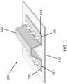
- Figure 1 shows some of the manufacturing steps, according to an embodiment of the method of the present invention, to obtain a composite structure. Particularly, figure 1 shows the provision of two partially cured FRP parts (110, 120) according to step a). More in particular, a first partially cured FRP part (110) and a second partially cured FRP part (120) are shown bonded together to form an ensemble (100) according to step b).
- Said ensemble (100) is formed by the union of two first bonding portions (111, 111') belonging to the first partially cured FRP part (110) with two respective second bonding portions (121, 121') of the second partially cured FRP part (120).
- the first partially cured FRP part (110) is a substantially flat panel
- the second partially cured FRP part (120) is an omega-profile stringer
- the second bonding portions (121, 121') of the second partially cured FRP part (120) are the two foot portions of the omega-profile stringer (120).
- Said omega-profile stringer (120) is joined to the substantially flat panel (110) through the foot portions (121, 121'), which are in contact with two corresponding first bonding portions (111, 111') of the substantially flat panel (110).
- a material-free enclosure is defined between the two foot portions (121, 121') of the omega-profile stringer (120), the inner side of the omega-profile stringer (120), and the portion of surface of the substantially flat panel (110) located between the two bonding portions (111, 111') contacting the foot portions (121, 121') of the omega-profile stringer (120).
- both partially cured FRP parts (110, 120) have been previously manufactured by applying a partial curing cycle, wherein the partial curing cycle is performed at a lower temperature compared to a temperature required to complete a curing cycle according to which the two partially cured FRP parts (110, 120) would be completely cured, and/or during a shorter time compared to a time required to complete a curing cycle according to which the two partially cured FRP parts (110, 120) would be completely cured.
- the two foot portions (121, 121') of the omega-profile stringer (120) and the two bonding portions (111, 111') of the substantially flat panel (110) have been subjected to respective surface treatments in order to enhance the properties of the integration between said partially cured FRP parts (110, 120) by cleaning and activating said surfaces that are intended to be bonded.
- surface treatments are plasma projection, corona discharge, grit blasting and/or laser abrading.
- step b) the integration of the partially cured FRP parts (110,120) to form the ensemble (100) shown according to step b) has been performed by applying temperature and a pressure between 0 and 9 bar to bring the two foot portions (121, 121') of the omega-profile stringer (120) and the two bonding portions (111, 111') of the substantially flat panel (110) into contact.
- omega-profile stringer (120) and substantially flat panel (110) have been integrated into an ensemble (100) by being subjected to a partial curing cycle performed at a lower temperature compared to a temperature required to achieve complete curing and/or during a shorter time compared to a time required to achieve complete curing.
- the manufacturing tool which is not presently claimed, comprises:
- the first mold part (210) is provided with a first pressing surface (211), and the second mold part (220) is provided with a second pressing surface (221), such that the first (211) and second (221) pressing surfaces are configured to be arranged facing each other when the first (210) and second (220) mold parts are coupled to each other.
- the first (210) and/or the second (220) mold part is provided with a pneumatic circuit (290) configured to air-tightly communicate the means to apply vacuum with the inner chamber through at least one vacuum valve (280) arranged on the first (210) and/or the second (220) mold part.
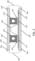
- Figure 2 schematically shows a manufacturing tooling according to the invention. Also, additional steps that an embodiment of the method of the invention follows to manufacture a composite structure are explained based on this figure, and, more in particular, the additional steps necessary to cure the ensemble (100) shown in Figure 1 .
- Figure 2 shows the provision of a mold, according to step c) inside of which is confined the ensemble (100) shown in Figure 1 .
- the mold comprises a first mold part (210) and a second mold part (220) configured for coupling with each other, such that an inner chamber is defined when the first (210) and second (220) mold parts are coupled to each other.
- said inner chamber corresponds to the space that separates the first (210) and the second (220) mold parts and where, as can be seen, the ensemble (100) is housed.
- the substantially flat panel (110) is shown resting on a flat surface of the first mold part (210) along its entire surface.
- the second mold part (220) is shown separated a certain height from the upper surface of the omega-profile stringer (120), which has a trapezoidal shape.
- Said second mold part (220) is shown comprising two blocks (222, 222')configured to contact the foot portions (121, 121') of the omega-profile stringer (120) along their entire upper side (i.e., the side which is not in contact with the substantially flat panel (110)) by means of two second pressing surfaces (221, 221'), respectively.
- first pressing surfaces (211, 211') of the first mold part (210) which are represented with dashed lines, are located opposite the two second pressing surfaces (221, 221') of the second mold part (220).
- the first (210) and second (220) mold parts are shown coupled to each other, such that the two first pressing surfaces (211, 211') of the first mold part (210) press against the two first bonding portions (111, 111') of the substantially flat panel (110); and the two second pressing surfaces (221, 221') of the second mold part (220) press against the two second bonding portions (121, 121'), i.e., the foot portions (121, 121'), of the omega-profile stringer (120).
- the exerted pressure presses the substantially flat panel (110) against the omega-profile stringer (120), i.e, the two foot portions (121, 121') of the omega-profile stringer (120) against the corresponding two bonding portions (111, 111') of the substantially flat panel (110).
- a vacuum is generated inside the inner chamber defined by said first (210) and second (220) parts of the mold, by means of a vacuum valve (230) arranged on at least one of the first (210) and second (220) mold parts, wherein said vacuum valve (230) establishes a fluidic communication between the inner chamber and the exterior of the first (210) and second (220) mold parts.
- step e) of the method vacuum is generated inside the inner chamber and, then, due to the atmospheric pressure, the closure force of the first (210) and second (220) parts of the mold corresponds to the product of the negative vacuum achieved and the size of the surface of both pairs of pressing surfaces (211, 211'; 221, 221').
- the coupling between said first (210) and second (220) mold parts is not airtight in this embodiment, since the lateral ends of the mold remain open, i.e., allowing fluidic communication between the inner chamber and the surrounding atmosphere of mold.
- Figure 2 shows the provision of sealing means (250) in conjunction with a vacuum bag (240) covering the lateral ends of the mold, making it possible to isolate said inner chamber and thus maintain vacuum conditions according to stage e) of the method.
- heat is applied to allow reaching the proper temperature to complete the polymerisation of the resin.
- Application of heat may be performed in different ways.
- step f) comprises introducing the mold housing the ensemble (100) in an oven.
- step f) comprises heating by means of heating means integrated in the first (210) and/or the second (220) mold parts.
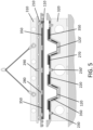
- Figure 3 shows another embodiment of the manufacturing tooling according to the present invention.
- the second mold part (220) has a geometry complementary to that of the omega-profile stringer (120), i.e. with a trapezoidal relief reproducing that of said omega-profile stringer (120) and allowing the second mold part (220) to couple with the first mold part (210) by fitting on the outer surface of said omega-profile stringer (120).
- Figure 3 shows two resilient blocks, each resilient block located between one of the two second pressing surfaces and the corresponding foot portion of the omega-profile stringer (120). More in particular, in this embodiment each resilient block comprises an inflatable bellow (260, 260') in contact with one of the two second pressing surfaces of the second mold part (220), and a resilient caul (270, 270') arranged between an inflatable bellow (260, 260') and the corresponding foot portion of the omega-profile stringer (120).
- each resilient block comprises an inflatable bellow (260, 260') in contact with one of the two second pressing surfaces of the second mold part (220), and a resilient caul (270, 270') arranged between an inflatable bellow (260, 260') and the corresponding foot portion of the omega-profile stringer (120).
- the interposition of a resilient block and, more particularly, of an inflatable bellow (260, 260') and a resilient caul (270, 270'), between a pressing surface of the second mold part (220) and the corresponding foot portion of the omega-profile stringer (120) allows to transmit uniformly the pressure exerted by the second mold part (220) through said pressing surface to the bonding portion during step d) of the method.
- the configuration of the manufacturing tooling shown in Figure 3 allows to control the internal pressure of the inflatable bellows (260, 260') for adjusting the pressure exerted on each corresponding foot portion of the omega-profile stringer (120).
- Figure 3 also depicts the first mold part (210) being provided with a pneumatic circuit (290) configured to air-tightly communicate a vacuum system with the inner chamber through at least one vacuum valve (280).
- a pneumatic circuit (290) configured to air-tightly communicate a vacuum system with the inner chamber through at least one vacuum valve (280).
- the substantially flat panel (110) is arranged on the first mold part (210) covering the vacuum valve (280).
- the substantially flat panel (110) is fixed to the first mold part (210) by the suction generated when vacuum is applied through the vacuum valve (280).
- the omega-profile stringer (120) is joined to the substantially flat panel (110) through two foot portions which are in contact with two corresponding bonding portions of said substantially flat panel (110), such that an enclosure free of material is defined between the two foot portions of the omega-profile stringer (120), the inner side of the omega-profile stringer (120), and the portion of surface of the substantially flat panel (110) located between the two bonding portions contacting the foot portions of the omega-profile stringer (120).
- the ensemble (100) is arranged such that the vacuum valve (280) is arranged contacting the portion of the substantially flat panel (110) defined between the two bonding portions contacting the foot portions of the omega-profile stringer (120).
- the portion of the substantially flat panel (110) defined between the two bonding portions contacting the foot portions of the omega-profile stringer is prevented, by means of said suction generated, to collapse, buckling or bending towards the interior of the enclosure free of material, due to the vacuum generated in the inner chamber according to step e) of the present embodiment of the method by means of the vacuum valves (230, 230') shown, respectively, in Figures 2 and 3 .
- step b) of the method may be performed at different moments.
- step b) is performed prior to steps c) and d). That is, the ensemble (100) of Figure 1 formed by a substantially flat panel (110) and an omega-profile stringer (120) is formed at a stage prior to inserting said ensemble (100) into the mold, as shown in Figures 2 and 3 .
- step b) is performed subsequently to steps c) and d).
- the partially cured FRP parts (110, 120, 120') are inserted in the mold before the partially cured FRP parts (110, 120, 120') are joined.
- a first partially cured FRP part is arranged on/attached to the first mold part
- a second partially cured FRP part is arranged on/attached to the second mold part
- the ensemble is formed when the first and second mold parts are coupled, enclosing the ensemble within the inner chamber
- two omega-profile stringers 120, 120' are intended to be bonded with a substantially flat panel (110). That is, more than two partially cured FRP parts are provided in step a) according to the embodiments shown. Accordingly, the first mold part (210) and the second mold part (220) are provided with a plurality of pairs of complementary pressing surfaces (i.e., a plurality of corresponding first or second pressing surfaces), each first pressing surface of the first mold part (210) being configured to be arranged facing a corresponding second pressing surface of the second mold part (220) when the first (210) and second (220 mold parts are coupled to each other.
- a plurality of pairs of complementary pressing surfaces i.e., a plurality of corresponding first or second pressing surfaces
- step d when the first (210) and second (220) mold parts are coupled according to step d), the four foot portions of the two omega-profile stringers (120, 120') are brought into contact with four corresponding bonding portions of the substantially flat panel (110), and are pressed against them, by four pairs of opposite pressing surfaces of the first (210) and second (220) mold parts.
- the second mold part (220) of the manufacturing tool is attached to a handling frame (320) which can be provided, according to further embodiments of the invention, for in-plant handling of mold parts (210, 220) with the appropriate industrial equipment, such as cranes.
- a handling frame (320) which can be provided, according to further embodiments of the invention, for in-plant handling of mold parts (210, 220) with the appropriate industrial equipment, such as cranes.
- two omega-profile stringers (120, 120') are fixed to the second mold part (220), which is provided with trapezoidal profile cavities, by means of complementary electromagnets (330, 340).
- the first mold part (210) is resting onto a support frame (310).
- a first partially cured FRP part (110) that is, the substantially flat panel (110) is fixed to the first mold part (210) by suction through a plurality of suction valves (280) connected by means of a pneumatic circuit (290) to a vacuum system.
- An ensemble is thus formed, according to step b) subsequently to steps c) and d), that is, when the first (210) and second (220) mold parts are coupled, enclosing the ensemble within the inner chamber.
- the first mold part (210) is attached to the handling frame (310), and, in turn, the substantially flat panel (110) is fixed to the first mold part (210) by suction through a plurality of suction valves (280) connected by means of a pneumatic circuit (290) to a vacuum system.
- the second mold part (220) is resting onto a support frame (320) and two omega-profile stringers (120, 120') are coupled to the second mold part (220) by being inserted into respective cavities provided with trapezoidal shape.
- both embodiments shown in figures 4 and 5 comprise heating means (350) integrated in the first (210) and the second (220) mold parts.
- the heating means (350) can be resistive, inductive, pneumatic or hydraulic.
Landscapes
- Engineering & Computer Science (AREA)
- Mechanical Engineering (AREA)
- Physics & Mathematics (AREA)
- Fluid Mechanics (AREA)
- Aviation & Aerospace Engineering (AREA)
- Health & Medical Sciences (AREA)
- Toxicology (AREA)
- Manufacturing & Machinery (AREA)
- Chemical & Material Sciences (AREA)
- Composite Materials (AREA)
- Transportation (AREA)
- Moulding By Coating Moulds (AREA)
Claims (13)
- Verfahren zur Herstellung einer Verbundstruktur, wobei das Verfahren die folgenden Schritte umfasst:a) Bereitstellen von wenigstens zwei teilgehärteten faserverstärkten Polymer(FRP)-Teilen (110, 120);b) Bilden eines Ensembles (100) durch Verbinden von wenigstens zwei teilgehärteten FRP-Teilen (110, 120) durch Inkontaktbringen eines ersten Bindeabschnitts (111) eines ersten teilgehärteten FRP-Teils (110) mit einem zweiten Bindeabschnitt (121) eines zweiten teilgehärteten FRP-Teils (120) ;c) Bereitstellen eines Formwerkzeugs, das ein erstes Formteil (210) und ein zweites Formteil (220) umfasst, die zum Koppeln miteinander gestaltet sind, so dass eine Innenkammer definiert ist, wenn das erste (210) und das zweite (220) Formteil miteinander gekoppelt sind, wobei die Innenkammer zur Aufnahme des Ensembles (100) im Inneren gestaltet ist, wobeidas erste Formteil (210) mit einer ersten Pressfläche (211) versehen ist unddas zweite Formteil (220) mit einer zweiten Pressfläche (221) versehen ist, wobei die erste (211) und die zweite (221) Pressfläche dafür gestaltet sind, einander zugewandt angeordnet zu sein, wenn das erste (210) und das zweite (220) Formteil aneinander gekoppelt sind;d) Koppeln des ersten (210) und des zweiten (220) Formteils, so dass das Ensemble (100) in die durch das erste (210) und das zweite (220) Formteil definierte Innenkammer aufgenommen wird, wobeidie erste Pressfläche (211) gegen den ersten Bindeabschnitt (111) des ersten teilgehärteten FRP-Teils (110) drückt und die zweite Pressfläche (221) gegen den zweiten Bindeabschnitt (121) des zweiten teilgehärteten FRP-Teils (120) drückt,so dass der von der ersten (211) und der zweiten (221) Pressfläche ausgeübte Druck den ersten (111) und den zweiten (121) Bindeabschnitt gegeneinander drückt;e) Erzeugen eines Vakuums in der Innenkammer; undf) Härten des Ensembles (100) unter Vakuum und Temperatur; dadurch gekennzeichnet, dass Schritt b) Anwenden von Druck, um den ersten Bindeabschnitt (111) und den zweiten Bindeabschnitt (121) in Kontakt zu bringen; und dasAnwenden eines Teilhärtungszyklus umfasst, wobei der Teilhärtungszyklus durchgeführt wird:- bei einer tieferen Temperatur im Vergleich zu einer Temperatur, die zum Vollenden eines Härtungszyklus, durch den die teilgehärteten FKP-Teile (110, 120) vollständig gehärtet werden, ausgelegt ist, und/oder- während einer kürzeren Zeit im Vergleich zu einer Zeit, die zum Vollenden eines Härtungszyklus, durch den die teilgehärteten FKP-Teile (110, 120) vollständig gehärtet werden, ausgelegt ist.
- Verfahren nach Anspruch 1, ferner umfassend vor Schritt a) Herstellen jedes teilgehärteten FRP-Teils (110, 120) durch Anwenden eines Teilhärtungszyklus, wobei der Teilhärtungszyklus durchgeführt wird:- bei einer tieferen Temperatur im Vergleich zu einer Temperatur, die zum Vollenden eines Härtungszyklus, durch den die teilgehärteten FKP-Teile (110, 120) vollständig gehärtet werden, erforderlich ist, und/oder- während einer kürzeren Zeit im Vergleich zu einer Zeit, die zum Vollenden eines Härtungszyklus, durch den die teilgehärteten FKP-Teile (110, 120) vollständig gehärtet werden, erforderlich ist.
- Verfahren nach einem der vorstehenden Ansprüche, ferner umfassend vor Schritt b) Durchführen einer Oberflächenbehandlung an dem ersten Bindeabschnitt (111) und/oder dem zweiten Bindeabschnitt (121), wie z.B. Plasmasprühen, Koronaentladung, Sandstrahlen und/oder Laserschleifen.
- Verfahren nach einem der vorstehenden Ansprüche, wobei Vakuum bei Schritt e) durch wenigstens ein Vakuumventil (230) erzeugt wird, das an wenigstens einem von dem ersten (210) und dem zweiten (220) Formteil angeordnet ist, wobei das Vakuumventil (230) eine Fluidverbindung zwischen der Innenkammer und dem Außenraum des ersten (210) und des zweiten (220) Formteils herstellt.
- Verfahren nach einem der vorstehenden Ansprüche, wobei Schritt e) Bereitstellen umfasst von:einem Vakuumbeutel (240), der den Verbindungsbereich zwischen dem ersten (210) und dem zweiten (220) Formteil wenigstens teilweise bedeckt; undDichtungsmitteln (250), die zum Abdichten der Verbindung zwischen dem Vakuumbeutel und ersten (210) und dem zweiten (220) Formteil gestaltet sind.
- Verfahren nach einem der vorstehenden Ansprüche, wobei Schritt d) Bereitstellen wenigstens eines elastischen Blocks umfasst zwischen:- der ersten Pressfläche (211) und dem ersten Bindeabschnitt (111) des ersten teilgehärteten FRP-Teils (110) und/oder- der zweiten Pressfläche (221) und dem zweiten Bindeabschnitt (121) des zweiten teilgehärteten FRP-Teils (120) .
- Verfahren nach Anspruch 6, wobei ein elastischer Block einen aufblasbaren Balg (260) in Kontakt mit entweder der ersten (211) oder der zweiten (221) Pressfläche und ein elastisches Kissen (270), das zwischen dem aufblasbaren Balg (260) und dem ersten (111) oder zweiten (121) Bindeabschnitt angeordnet ist, umfasst.
- Verfahren nach Anspruch 7, ferner umfassend Steuern des Innendrucks eines aufblasbaren Balgs (260) zum Einstellen des Drucks, der auf einen entsprechenden ersten (111) oder zweiten (121) Bindeabschnitt eines entsprechenden ersten (110) oder zweiten (120) teilgehärteten FRP-Teils ausgeübt wird.
- Verfahren nach einem der vorstehenden Ansprüche, wobei Schritt f) Einführen der Form, die das Ensemble (100) enthält, in einen Ofen umfasst.
- Verfahren nach einem der vorstehenden Ansprüche, wobei Schritt f) Erhitzen mithilfe von Heizmitteln umfasst, die in das erste (210) und/oder zweite (220) Formteil integriert sind.
- Verfahren nach einem der vorstehenden Ansprüche, ferner umfassend nach Härten des Ensembles (100) nach Schritt f) Abkühlen des Ensembles (100).
- Verfahren nach einem der vorstehenden Ansprüche, wobei das erste teilgehärtete FRP-Teil (110) eine im Wesentlichen flache Platte ist und wobei das erste Formteil (210) mit einem pneumatischen Kreis (290) versehen ist, der dafür gestaltet ist, ein Vakuumsystem durch wenigstens ein Vakuumventil (280) luftdicht mit der Innenkammer zu verbinden,und wobei bei Schritt d)die im Wesentlichen flache Platte (110) wenigstens ein Vakuumventil (280) bedeckend auf dem ersten Formteil (210) angeordnet wird; unddurch das Vakuumventil (280) Vakuum angelegt wird, wodurch die im Wesentlichen flache Platte (110) durch die erzeugte Saugwirkung an dem ersten Formteil (210) fixiert wird.
- Verfahren nach Anspruch 12, wobei das zweite teilgehärtete FRP-Teil (120) ein Omega-Profil-Stringer ist, der dazu gestaltet ist, mit der im Wesentlichen flachen Platte (110) durch zwei Fußabschnitte (121, 121') des Omega-Profil-Stringers (120) verbunden zu werden, die zum Kontakt mit zwei entsprechenden Bindeabschnitten (111, 111') der im Wesentlichen flachen Platte (110) gestaltet sind, so dass eine materialfreie Einfassung zwischen den beiden Fußabschnitten (121, 121') des Omega-Profil-Stringers (120) definiert ist, wobei die Innenseite des Omega-Profil-Stringers (120) und der Abschnitt der Oberfläche der im Wesentlichen flachen Platte (110), der sich zwischen den beiden Bindeabschnitten (111, 111') befindet, Kontakt mit den Fußabschnitten (121, 121') des Omega-Profil-Stringers (120) bilden;wobei bei Schritt d)das Ensemble (100) so angeordnet wird, dass wenigstens ein Vakuumventil (280) in Kontakt mit dem Abschnitt der im Wesentlichen flachen Platte (110) angeordnet ist, der zwischen den beiden Bindeabschnitten (111, 111') in Kontakt mit den Fußabschnitten (121, 121') des Omega-Profil-Stringers (120) angeordnet ist.
Priority Applications (4)
| Application Number | Priority Date | Filing Date | Title |
|---|---|---|---|
| ES22382545T ES3008057T3 (en) | 2022-06-08 | 2022-06-08 | Composite manufacturing method |
| EP22382545.6A EP4289604B1 (de) | 2022-06-08 | 2022-06-08 | Verfahren zur herstellung von verbundwerkstoff |
| CN202310559089.4A CN117183403A (zh) | 2022-06-08 | 2023-05-17 | 用于制造复合结构的方法及制造工具 |
| US18/330,125 US20230398750A1 (en) | 2022-06-08 | 2023-06-06 | Composite manufacturing method and tool |
Applications Claiming Priority (1)
| Application Number | Priority Date | Filing Date | Title |
|---|---|---|---|
| EP22382545.6A EP4289604B1 (de) | 2022-06-08 | 2022-06-08 | Verfahren zur herstellung von verbundwerkstoff |
Publications (2)
| Publication Number | Publication Date |
|---|---|
| EP4289604A1 EP4289604A1 (de) | 2023-12-13 |
| EP4289604B1 true EP4289604B1 (de) | 2024-12-18 |
Family
ID=82117343
Family Applications (1)
| Application Number | Title | Priority Date | Filing Date |
|---|---|---|---|
| EP22382545.6A Active EP4289604B1 (de) | 2022-06-08 | 2022-06-08 | Verfahren zur herstellung von verbundwerkstoff |
Country Status (4)
| Country | Link |
|---|---|
| US (1) | US20230398750A1 (de) |
| EP (1) | EP4289604B1 (de) |
| CN (1) | CN117183403A (de) |
| ES (1) | ES3008057T3 (de) |
Family Cites Families (8)
| Publication number | Priority date | Publication date | Assignee | Title |
|---|---|---|---|---|
| JP4921194B2 (ja) * | 2007-01-31 | 2012-04-25 | トヨタ紡織株式会社 | 表皮材の接着装置、及び、表皮材の接着方法 |
| US8834668B2 (en) * | 2008-11-19 | 2014-09-16 | The Boeing Company | Staged cocuring of composite structures |
| US20130115440A1 (en) * | 2010-05-28 | 2013-05-09 | Bernd Hoevel | Composites |
| US8262841B2 (en) * | 2010-11-24 | 2012-09-11 | The Boeing Company | Methods for void-free debulking of adhesive bonded joints |
| CN103895152A (zh) * | 2012-12-29 | 2014-07-02 | 深圳富泰宏精密工业有限公司 | 复合体及其制备方法 |
| US11104113B2 (en) * | 2017-04-19 | 2021-08-31 | The Boeing Company | Systems and methods for assembling elongate composite structures |
| DE102018105765A1 (de) * | 2018-03-13 | 2019-09-19 | Deutsches Zentrum für Luft- und Raumfahrt e.V. | Verfahren zum Herstellen eines Faserverbund-Hohlbauteils und Faserverbund-Hohlbauteil |
| JP2022080869A (ja) * | 2020-11-18 | 2022-05-30 | ザ・ボーイング・カンパニー | 航空機製造のための当て板システム |
-
2022
- 2022-06-08 ES ES22382545T patent/ES3008057T3/es active Active
- 2022-06-08 EP EP22382545.6A patent/EP4289604B1/de active Active
-
2023
- 2023-05-17 CN CN202310559089.4A patent/CN117183403A/zh active Pending
- 2023-06-06 US US18/330,125 patent/US20230398750A1/en active Pending
Also Published As
| Publication number | Publication date |
|---|---|
| US20230398750A1 (en) | 2023-12-14 |
| CN117183403A (zh) | 2023-12-08 |
| EP4289604A1 (de) | 2023-12-13 |
| ES3008057T3 (en) | 2025-03-21 |
Similar Documents
| Publication | Publication Date | Title |
|---|---|---|
| US6254812B1 (en) | Method of making a composite part using a compliant forming surface | |
| EP0904929B1 (de) | Verfahren zum Formen eines inneren Druckstücks während des Formen eines Produktes | |
| US8834782B2 (en) | Composite structures and methods of making same | |
| EP0805747B1 (de) | Verfahren zur herstellung mit einem wabenförmigen kern versehener verbundwerkstoffe | |
| US9284035B2 (en) | Composite tubular-reinforced integrated structural panels with mutually intersecting stiffeners and fabrication processes | |
| TW201304940A (zh) | 纖維強化樹脂與輕量化芯部之複合材料及製造其之方法與裝置 | |
| KR101198625B1 (ko) | 차량용 금속?복합재료 하이브리드 휠의 제조방법 | |
| CN112454938A (zh) | 一种碳纤维蜂窝夹心复合材料构件的成型方法 | |
| US10710327B2 (en) | Methods for making composite parts from stacked partially cured sublaminate units | |
| JP2009542483A (ja) | 複合部品の製造方法 | |
| JP5445037B2 (ja) | 繊維強化プラスチック構造体およびその製造方法 | |
| US20020135093A1 (en) | Method and apparatus for controlling thickness during lay-up and fabrication of composite components | |
| EP3789191B1 (de) | Verfahren zur herstellung einer verbundmaterialstruktur unter verwendung eines cohärtungsverfahrens | |
| CN110104202B (zh) | 使用铰接式芯轴的复合飞机制造工具 | |
| JP2003071864A (ja) | 複合材補強板の製造方法 | |
| US11458719B2 (en) | Method for joining by bonding of parts, in particular composite parts having fibrous reinforcement | |
| US20140360665A1 (en) | Reflector manufactured using multiple use precision extractable tooling | |
| EP4289604B1 (de) | Verfahren zur herstellung von verbundwerkstoff | |
| CN114311731A (zh) | 耐高温双马树脂基复合材料分段固化成型的方法 | |
| EP4633902A1 (de) | Elastomerer werkzeugbalg und verfahren zu seiner herstellung | |
| CN114536813B (zh) | 用于处理复合结构的设备和方法 | |
| Legrand et al. | A study of the feasibility of a monoblock racing motorcycle rim | |
| EP4122682A1 (de) | Verfahren zur herstellung einer verbundboxstruktur | |
| CN121843810A (zh) | 制造纤维增强复合材料制品的方法 | |
| CN118061560A (zh) | 用于将配件集成到型材的翼部之间的方法 |
Legal Events
| Date | Code | Title | Description |
|---|---|---|---|
| PUAI | Public reference made under article 153(3) epc to a published international application that has entered the european phase |
Free format text: ORIGINAL CODE: 0009012 |
|
| STAA | Information on the status of an ep patent application or granted ep patent |
Free format text: STATUS: THE APPLICATION HAS BEEN PUBLISHED |
|
| AK | Designated contracting states |
Kind code of ref document: A1 Designated state(s): AL AT BE BG CH CY CZ DE DK EE ES FI FR GB GR HR HU IE IS IT LI LT LU LV MC MK MT NL NO PL PT RO RS SE SI SK SM TR |
|
| STAA | Information on the status of an ep patent application or granted ep patent |
Free format text: STATUS: REQUEST FOR EXAMINATION WAS MADE |
|
| 17P | Request for examination filed |
Effective date: 20240605 |
|
| RBV | Designated contracting states (corrected) |
Designated state(s): AL AT BE BG CH CY CZ DE DK EE ES FI FR GB GR HR HU IE IS IT LI LT LU LV MC MK MT NL NO PL PT RO RS SE SI SK SM TR |
|
| GRAP | Despatch of communication of intention to grant a patent |
Free format text: ORIGINAL CODE: EPIDOSNIGR1 |
|
| STAA | Information on the status of an ep patent application or granted ep patent |
Free format text: STATUS: GRANT OF PATENT IS INTENDED |
|
| RIC1 | Information provided on ipc code assigned before grant |
Ipc: B64C 3/26 20060101ALN20240628BHEP Ipc: B64C 1/12 20060101ALN20240628BHEP Ipc: B29L 31/30 20060101ALN20240628BHEP Ipc: B29K 105/06 20060101ALN20240628BHEP Ipc: B29C 65/18 20060101ALI20240628BHEP Ipc: B64C 1/06 20060101ALI20240628BHEP Ipc: B64F 5/10 20170101ALI20240628BHEP Ipc: B29C 65/78 20060101ALI20240628BHEP Ipc: B29C 65/22 20060101ALI20240628BHEP Ipc: B29C 65/02 20060101AFI20240628BHEP |
|
| INTG | Intention to grant announced |
Effective date: 20240802 |
|
| GRAS | Grant fee paid |
Free format text: ORIGINAL CODE: EPIDOSNIGR3 |
|
| GRAA | (expected) grant |
Free format text: ORIGINAL CODE: 0009210 |
|
| STAA | Information on the status of an ep patent application or granted ep patent |
Free format text: STATUS: THE PATENT HAS BEEN GRANTED |
|
| AK | Designated contracting states |
Kind code of ref document: B1 Designated state(s): AL AT BE BG CH CY CZ DE DK EE ES FI FR GB GR HR HU IE IS IT LI LT LU LV MC MK MT NL NO PL PT RO RS SE SI SK SM TR |
|
| REG | Reference to a national code |
Ref country code: CH Ref legal event code: EP |
|
| REG | Reference to a national code |
Ref country code: DE Ref legal event code: R096 Ref document number: 602022008831 Country of ref document: DE |
|
| REG | Reference to a national code |
Ref country code: IE Ref legal event code: FG4D |
|
| REG | Reference to a national code |
Ref country code: ES Ref legal event code: FG2A Ref document number: 3008057 Country of ref document: ES Kind code of ref document: T3 Effective date: 20250321 |
|
| REG | Reference to a national code |
Ref country code: LT Ref legal event code: MG9D |
|
| PG25 | Lapsed in a contracting state [announced via postgrant information from national office to epo] |
Ref country code: HR Free format text: LAPSE BECAUSE OF FAILURE TO SUBMIT A TRANSLATION OF THE DESCRIPTION OR TO PAY THE FEE WITHIN THE PRESCRIBED TIME-LIMIT Effective date: 20241218 |
|
| PG25 | Lapsed in a contracting state [announced via postgrant information from national office to epo] |
Ref country code: FI Free format text: LAPSE BECAUSE OF FAILURE TO SUBMIT A TRANSLATION OF THE DESCRIPTION OR TO PAY THE FEE WITHIN THE PRESCRIBED TIME-LIMIT Effective date: 20241218 |
|
| PG25 | Lapsed in a contracting state [announced via postgrant information from national office to epo] |
Ref country code: BG Free format text: LAPSE BECAUSE OF FAILURE TO SUBMIT A TRANSLATION OF THE DESCRIPTION OR TO PAY THE FEE WITHIN THE PRESCRIBED TIME-LIMIT Effective date: 20241218 |
|
| PG25 | Lapsed in a contracting state [announced via postgrant information from national office to epo] |
Ref country code: NO Free format text: LAPSE BECAUSE OF FAILURE TO SUBMIT A TRANSLATION OF THE DESCRIPTION OR TO PAY THE FEE WITHIN THE PRESCRIBED TIME-LIMIT Effective date: 20250318 |
|
| REG | Reference to a national code |
Ref country code: NL Ref legal event code: MP Effective date: 20241218 |
|
| PG25 | Lapsed in a contracting state [announced via postgrant information from national office to epo] |
Ref country code: LV Free format text: LAPSE BECAUSE OF FAILURE TO SUBMIT A TRANSLATION OF THE DESCRIPTION OR TO PAY THE FEE WITHIN THE PRESCRIBED TIME-LIMIT Effective date: 20241218 Ref country code: GR Free format text: LAPSE BECAUSE OF FAILURE TO SUBMIT A TRANSLATION OF THE DESCRIPTION OR TO PAY THE FEE WITHIN THE PRESCRIBED TIME-LIMIT Effective date: 20250319 |
|
| PG25 | Lapsed in a contracting state [announced via postgrant information from national office to epo] |
Ref country code: RS Free format text: LAPSE BECAUSE OF FAILURE TO SUBMIT A TRANSLATION OF THE DESCRIPTION OR TO PAY THE FEE WITHIN THE PRESCRIBED TIME-LIMIT Effective date: 20250318 |
|
| PG25 | Lapsed in a contracting state [announced via postgrant information from national office to epo] |
Ref country code: NL Free format text: LAPSE BECAUSE OF FAILURE TO SUBMIT A TRANSLATION OF THE DESCRIPTION OR TO PAY THE FEE WITHIN THE PRESCRIBED TIME-LIMIT Effective date: 20241218 |
|
| REG | Reference to a national code |
Ref country code: AT Ref legal event code: MK05 Ref document number: 1751932 Country of ref document: AT Kind code of ref document: T Effective date: 20241218 |
|
| PG25 | Lapsed in a contracting state [announced via postgrant information from national office to epo] |
Ref country code: SM Free format text: LAPSE BECAUSE OF FAILURE TO SUBMIT A TRANSLATION OF THE DESCRIPTION OR TO PAY THE FEE WITHIN THE PRESCRIBED TIME-LIMIT Effective date: 20241218 |
|
| PG25 | Lapsed in a contracting state [announced via postgrant information from national office to epo] |
Ref country code: PL Free format text: LAPSE BECAUSE OF FAILURE TO SUBMIT A TRANSLATION OF THE DESCRIPTION OR TO PAY THE FEE WITHIN THE PRESCRIBED TIME-LIMIT Effective date: 20241218 |
|
| PGFP | Annual fee paid to national office [announced via postgrant information from national office to epo] |
Ref country code: DE Payment date: 20250618 Year of fee payment: 4 |
|
| PG25 | Lapsed in a contracting state [announced via postgrant information from national office to epo] |
Ref country code: IS Free format text: LAPSE BECAUSE OF FAILURE TO SUBMIT A TRANSLATION OF THE DESCRIPTION OR TO PAY THE FEE WITHIN THE PRESCRIBED TIME-LIMIT Effective date: 20250418 |
|
| PG25 | Lapsed in a contracting state [announced via postgrant information from national office to epo] |
Ref country code: PT Free format text: LAPSE BECAUSE OF FAILURE TO SUBMIT A TRANSLATION OF THE DESCRIPTION OR TO PAY THE FEE WITHIN THE PRESCRIBED TIME-LIMIT Effective date: 20250421 |
|
| PG25 | Lapsed in a contracting state [announced via postgrant information from national office to epo] |
Ref country code: EE Free format text: LAPSE BECAUSE OF FAILURE TO SUBMIT A TRANSLATION OF THE DESCRIPTION OR TO PAY THE FEE WITHIN THE PRESCRIBED TIME-LIMIT Effective date: 20241218 |
|
| PGFP | Annual fee paid to national office [announced via postgrant information from national office to epo] |
Ref country code: FR Payment date: 20250627 Year of fee payment: 4 |
|
| PG25 | Lapsed in a contracting state [announced via postgrant information from national office to epo] |
Ref country code: AT Free format text: LAPSE BECAUSE OF FAILURE TO SUBMIT A TRANSLATION OF THE DESCRIPTION OR TO PAY THE FEE WITHIN THE PRESCRIBED TIME-LIMIT Effective date: 20241218 Ref country code: RO Free format text: LAPSE BECAUSE OF FAILURE TO SUBMIT A TRANSLATION OF THE DESCRIPTION OR TO PAY THE FEE WITHIN THE PRESCRIBED TIME-LIMIT Effective date: 20241218 |
|
| PG25 | Lapsed in a contracting state [announced via postgrant information from national office to epo] |
Ref country code: SK Free format text: LAPSE BECAUSE OF FAILURE TO SUBMIT A TRANSLATION OF THE DESCRIPTION OR TO PAY THE FEE WITHIN THE PRESCRIBED TIME-LIMIT Effective date: 20241218 |
|
| PG25 | Lapsed in a contracting state [announced via postgrant information from national office to epo] |
Ref country code: CZ Free format text: LAPSE BECAUSE OF FAILURE TO SUBMIT A TRANSLATION OF THE DESCRIPTION OR TO PAY THE FEE WITHIN THE PRESCRIBED TIME-LIMIT Effective date: 20241218 |
|
| PG25 | Lapsed in a contracting state [announced via postgrant information from national office to epo] |
Ref country code: IT Free format text: LAPSE BECAUSE OF FAILURE TO SUBMIT A TRANSLATION OF THE DESCRIPTION OR TO PAY THE FEE WITHIN THE PRESCRIBED TIME-LIMIT Effective date: 20241218 |
|
| PG25 | Lapsed in a contracting state [announced via postgrant information from national office to epo] |
Ref country code: SE Free format text: LAPSE BECAUSE OF FAILURE TO SUBMIT A TRANSLATION OF THE DESCRIPTION OR TO PAY THE FEE WITHIN THE PRESCRIBED TIME-LIMIT Effective date: 20241218 |
|
| REG | Reference to a national code |
Ref country code: DE Ref legal event code: R097 Ref document number: 602022008831 Country of ref document: DE |
|
| PGFP | Annual fee paid to national office [announced via postgrant information from national office to epo] |
Ref country code: ES Payment date: 20250731 Year of fee payment: 4 |
|
| PG25 | Lapsed in a contracting state [announced via postgrant information from national office to epo] |
Ref country code: DK Free format text: LAPSE BECAUSE OF FAILURE TO SUBMIT A TRANSLATION OF THE DESCRIPTION OR TO PAY THE FEE WITHIN THE PRESCRIBED TIME-LIMIT Effective date: 20241218 |
|
| PLBE | No opposition filed within time limit |
Free format text: ORIGINAL CODE: 0009261 |
|
| STAA | Information on the status of an ep patent application or granted ep patent |
Free format text: STATUS: NO OPPOSITION FILED WITHIN TIME LIMIT |
|
| REG | Reference to a national code |
Ref country code: CH Ref legal event code: L10 Free format text: ST27 STATUS EVENT CODE: U-0-0-L10-L00 (AS PROVIDED BY THE NATIONAL OFFICE) Effective date: 20251029 |
|
| 26N | No opposition filed |
Effective date: 20250919 |
|
| REG | Reference to a national code |
Ref country code: CH Ref legal event code: H13 Free format text: ST27 STATUS EVENT CODE: U-0-0-H10-H13 (AS PROVIDED BY THE NATIONAL OFFICE) Effective date: 20260127 |
|
| PG25 | Lapsed in a contracting state [announced via postgrant information from national office to epo] |
Ref country code: MC Free format text: LAPSE BECAUSE OF FAILURE TO SUBMIT A TRANSLATION OF THE DESCRIPTION OR TO PAY THE FEE WITHIN THE PRESCRIBED TIME-LIMIT Effective date: 20241218 |
|
| PG25 | Lapsed in a contracting state [announced via postgrant information from national office to epo] |
Ref country code: LU Free format text: LAPSE BECAUSE OF NON-PAYMENT OF DUE FEES Effective date: 20250608 |
|
| REG | Reference to a national code |
Ref country code: BE Ref legal event code: MM Effective date: 20250630 |
|
| PG25 | Lapsed in a contracting state [announced via postgrant information from national office to epo] |
Ref country code: IE Free format text: LAPSE BECAUSE OF NON-PAYMENT OF DUE FEES Effective date: 20250608 |
|
| PG25 | Lapsed in a contracting state [announced via postgrant information from national office to epo] |
Ref country code: BE Free format text: LAPSE BECAUSE OF NON-PAYMENT OF DUE FEES Effective date: 20250630 |
|
| PG25 | Lapsed in a contracting state [announced via postgrant information from national office to epo] |
Ref country code: CH Free format text: LAPSE BECAUSE OF NON-PAYMENT OF DUE FEES Effective date: 20250630 |