EP4289594A1 - Spacer for harness bundle - Google Patents
Spacer for harness bundle Download PDFInfo
- Publication number
- EP4289594A1 EP4289594A1 EP22177687.5A EP22177687A EP4289594A1 EP 4289594 A1 EP4289594 A1 EP 4289594A1 EP 22177687 A EP22177687 A EP 22177687A EP 4289594 A1 EP4289594 A1 EP 4289594A1
- Authority
- EP
- European Patent Office
- Prior art keywords
- spacer
- maintained
- pieces
- mold
- wires
- Prior art date
- Legal status (The legal status is an assumption and is not a legal conclusion. Google has not performed a legal analysis and makes no representation as to the accuracy of the status listed.)
- Granted
Links
Images




Classifications
-
- B—PERFORMING OPERATIONS; TRANSPORTING
- B29—WORKING OF PLASTICS; WORKING OF SUBSTANCES IN A PLASTIC STATE IN GENERAL
- B29C—SHAPING OR JOINING OF PLASTICS; SHAPING OF MATERIAL IN A PLASTIC STATE, NOT OTHERWISE PROVIDED FOR; AFTER-TREATMENT OF THE SHAPED PRODUCTS, e.g. REPAIRING
- B29C45/00—Injection moulding, i.e. forcing the required volume of moulding material through a nozzle into a closed mould; Apparatus therefor
- B29C45/14—Injection moulding, i.e. forcing the required volume of moulding material through a nozzle into a closed mould; Apparatus therefor incorporating preformed parts or layers, e.g. injection moulding around inserts or for coating articles
- B29C45/14336—Coating a portion of the article, e.g. the edge of the article
- B29C45/14377—Coating a portion of the article, e.g. the edge of the article using an additional insert, e.g. a fastening element
-
- B—PERFORMING OPERATIONS; TRANSPORTING
- B29—WORKING OF PLASTICS; WORKING OF SUBSTANCES IN A PLASTIC STATE IN GENERAL
- B29C—SHAPING OR JOINING OF PLASTICS; SHAPING OF MATERIAL IN A PLASTIC STATE, NOT OTHERWISE PROVIDED FOR; AFTER-TREATMENT OF THE SHAPED PRODUCTS, e.g. REPAIRING
- B29C45/00—Injection moulding, i.e. forcing the required volume of moulding material through a nozzle into a closed mould; Apparatus therefor
- B29C45/14—Injection moulding, i.e. forcing the required volume of moulding material through a nozzle into a closed mould; Apparatus therefor incorporating preformed parts or layers, e.g. injection moulding around inserts or for coating articles
- B29C45/14065—Positioning or centering articles in the mould
-
- B—PERFORMING OPERATIONS; TRANSPORTING
- B29—WORKING OF PLASTICS; WORKING OF SUBSTANCES IN A PLASTIC STATE IN GENERAL
- B29C—SHAPING OR JOINING OF PLASTICS; SHAPING OF MATERIAL IN A PLASTIC STATE, NOT OTHERWISE PROVIDED FOR; AFTER-TREATMENT OF THE SHAPED PRODUCTS, e.g. REPAIRING
- B29C45/00—Injection moulding, i.e. forcing the required volume of moulding material through a nozzle into a closed mould; Apparatus therefor
- B29C45/14—Injection moulding, i.e. forcing the required volume of moulding material through a nozzle into a closed mould; Apparatus therefor incorporating preformed parts or layers, e.g. injection moulding around inserts or for coating articles
- B29C45/14467—Joining articles or parts of a single article
-
- B—PERFORMING OPERATIONS; TRANSPORTING
- B29—WORKING OF PLASTICS; WORKING OF SUBSTANCES IN A PLASTIC STATE IN GENERAL
- B29C—SHAPING OR JOINING OF PLASTICS; SHAPING OF MATERIAL IN A PLASTIC STATE, NOT OTHERWISE PROVIDED FOR; AFTER-TREATMENT OF THE SHAPED PRODUCTS, e.g. REPAIRING
- B29C45/00—Injection moulding, i.e. forcing the required volume of moulding material through a nozzle into a closed mould; Apparatus therefor
- B29C45/14—Injection moulding, i.e. forcing the required volume of moulding material through a nozzle into a closed mould; Apparatus therefor incorporating preformed parts or layers, e.g. injection moulding around inserts or for coating articles
- B29C45/14549—Coating rod-like, wire-like or belt-like articles
-
- B—PERFORMING OPERATIONS; TRANSPORTING
- B29—WORKING OF PLASTICS; WORKING OF SUBSTANCES IN A PLASTIC STATE IN GENERAL
- B29C—SHAPING OR JOINING OF PLASTICS; SHAPING OF MATERIAL IN A PLASTIC STATE, NOT OTHERWISE PROVIDED FOR; AFTER-TREATMENT OF THE SHAPED PRODUCTS, e.g. REPAIRING
- B29C45/00—Injection moulding, i.e. forcing the required volume of moulding material through a nozzle into a closed mould; Apparatus therefor
- B29C45/14—Injection moulding, i.e. forcing the required volume of moulding material through a nozzle into a closed mould; Apparatus therefor incorporating preformed parts or layers, e.g. injection moulding around inserts or for coating articles
- B29C45/14639—Injection moulding, i.e. forcing the required volume of moulding material through a nozzle into a closed mould; Apparatus therefor incorporating preformed parts or layers, e.g. injection moulding around inserts or for coating articles for obtaining an insulating effect, e.g. for electrical components
-
- B—PERFORMING OPERATIONS; TRANSPORTING
- B60—VEHICLES IN GENERAL
- B60R—VEHICLES, VEHICLE FITTINGS, OR VEHICLE PARTS, NOT OTHERWISE PROVIDED FOR
- B60R16/00—Electric or fluid circuits specially adapted for vehicles and not otherwise provided for; Arrangement of elements of electric or fluid circuits specially adapted for vehicles and not otherwise provided for
- B60R16/02—Electric or fluid circuits specially adapted for vehicles and not otherwise provided for; Arrangement of elements of electric or fluid circuits specially adapted for vehicles and not otherwise provided for electric constitutive elements
- B60R16/0207—Wire harnesses
- B60R16/0215—Protecting, fastening and routing means therefor
-
- H—ELECTRICITY
- H01—ELECTRIC ELEMENTS
- H01B—CABLES; CONDUCTORS; INSULATORS; SELECTION OF MATERIALS FOR THEIR CONDUCTIVE, INSULATING OR DIELECTRIC PROPERTIES
- H01B13/00—Apparatus or processes specially adapted for manufacturing conductors or cables
- H01B13/012—Apparatus or processes specially adapted for manufacturing conductors or cables for manufacturing wire harnesses
- H01B13/01209—Details
-
- B—PERFORMING OPERATIONS; TRANSPORTING
- B29—WORKING OF PLASTICS; WORKING OF SUBSTANCES IN A PLASTIC STATE IN GENERAL
- B29C—SHAPING OR JOINING OF PLASTICS; SHAPING OF MATERIAL IN A PLASTIC STATE, NOT OTHERWISE PROVIDED FOR; AFTER-TREATMENT OF THE SHAPED PRODUCTS, e.g. REPAIRING
- B29C45/00—Injection moulding, i.e. forcing the required volume of moulding material through a nozzle into a closed mould; Apparatus therefor
- B29C45/14—Injection moulding, i.e. forcing the required volume of moulding material through a nozzle into a closed mould; Apparatus therefor incorporating preformed parts or layers, e.g. injection moulding around inserts or for coating articles
- B29C45/14065—Positioning or centering articles in the mould
- B29C2045/14131—Positioning or centering articles in the mould using positioning or centering means forming part of the insert
-
- B—PERFORMING OPERATIONS; TRANSPORTING
- B29—WORKING OF PLASTICS; WORKING OF SUBSTANCES IN A PLASTIC STATE IN GENERAL
- B29C—SHAPING OR JOINING OF PLASTICS; SHAPING OF MATERIAL IN A PLASTIC STATE, NOT OTHERWISE PROVIDED FOR; AFTER-TREATMENT OF THE SHAPED PRODUCTS, e.g. REPAIRING
- B29C45/00—Injection moulding, i.e. forcing the required volume of moulding material through a nozzle into a closed mould; Apparatus therefor
- B29C45/14—Injection moulding, i.e. forcing the required volume of moulding material through a nozzle into a closed mould; Apparatus therefor incorporating preformed parts or layers, e.g. injection moulding around inserts or for coating articles
- B29C45/14065—Positioning or centering articles in the mould
- B29C2045/14147—Positioning or centering articles in the mould using pins or needles penetrating through the insert
-
- B—PERFORMING OPERATIONS; TRANSPORTING
- B29—WORKING OF PLASTICS; WORKING OF SUBSTANCES IN A PLASTIC STATE IN GENERAL
- B29C—SHAPING OR JOINING OF PLASTICS; SHAPING OF MATERIAL IN A PLASTIC STATE, NOT OTHERWISE PROVIDED FOR; AFTER-TREATMENT OF THE SHAPED PRODUCTS, e.g. REPAIRING
- B29C45/00—Injection moulding, i.e. forcing the required volume of moulding material through a nozzle into a closed mould; Apparatus therefor
- B29C45/14—Injection moulding, i.e. forcing the required volume of moulding material through a nozzle into a closed mould; Apparatus therefor incorporating preformed parts or layers, e.g. injection moulding around inserts or for coating articles
- B29C45/14065—Positioning or centering articles in the mould
- B29C2045/14163—Positioning or centering articles in the mould using springs being part of the positioning means
-
- B—PERFORMING OPERATIONS; TRANSPORTING
- B29—WORKING OF PLASTICS; WORKING OF SUBSTANCES IN A PLASTIC STATE IN GENERAL
- B29K—INDEXING SCHEME ASSOCIATED WITH SUBCLASSES B29B, B29C OR B29D, RELATING TO MOULDING MATERIALS OR TO MATERIALS FOR MOULDS, REINFORCEMENTS, FILLERS OR PREFORMED PARTS, e.g. INSERTS
- B29K2075/00—Use of PU, i.e. polyureas or polyurethanes or derivatives thereof, as moulding material
-
- B—PERFORMING OPERATIONS; TRANSPORTING
- B29—WORKING OF PLASTICS; WORKING OF SUBSTANCES IN A PLASTIC STATE IN GENERAL
- B29K—INDEXING SCHEME ASSOCIATED WITH SUBCLASSES B29B, B29C OR B29D, RELATING TO MOULDING MATERIALS OR TO MATERIALS FOR MOULDS, REINFORCEMENTS, FILLERS OR PREFORMED PARTS, e.g. INSERTS
- B29K2075/00—Use of PU, i.e. polyureas or polyurethanes or derivatives thereof, as moulding material
- B29K2075/02—Polyureas
-
- B—PERFORMING OPERATIONS; TRANSPORTING
- B29—WORKING OF PLASTICS; WORKING OF SUBSTANCES IN A PLASTIC STATE IN GENERAL
- B29L—INDEXING SCHEME ASSOCIATED WITH SUBCLASS B29C, RELATING TO PARTICULAR ARTICLES
- B29L2031/00—Other particular articles
- B29L2031/34—Electrical apparatus, e.g. sparking plugs or parts thereof
- B29L2031/3462—Cables
-
- H—ELECTRICITY
- H01—ELECTRIC ELEMENTS
- H01B—CABLES; CONDUCTORS; INSULATORS; SELECTION OF MATERIALS FOR THEIR CONDUCTIVE, INSULATING OR DIELECTRIC PROPERTIES
- H01B13/00—Apparatus or processes specially adapted for manufacturing conductors or cables
- H01B13/012—Apparatus or processes specially adapted for manufacturing conductors or cables for manufacturing wire harnesses
- H01B13/01263—Tying, wrapping, binding, lacing, strapping or sheathing harnesses
Definitions
- the present disclosure relates to a spacer for maintaining one or more wires, or one or more harnesses, or bundles or generally speaking pieces to be maintained, in particular during molding process, and a method of manufacturing over molded wires. This is of interest in the automotive industry in particular.
- Highly resistant polyurethane foam sealing of single wires or wire bundles is a standard sealing for firewall grommets.
- Polyurethane foam can be used also for other applications, for example splice over molding, rigid wiring and ring terminal sealing cups.
- the document GB2243254A discloses a spacer for two or more cables or cable cores comprising a star-shaped body of stiff material having radial arms locating the cores or cables at a predetermined distance from each other, and an annulus of stiff material encompassing said cables or cores.
- the present disclosure concerns a spacer for maintaining one or more pieces during a molding process, the spacer having:
- a leaf may be defined as a thin sheet or plate of any substance. That is, the spring curved leaf is a leaf which is curved, is flexible and allows for a spring effect (elastic return force). Flexible is to be understood as capable of movement, in contrast with the external frame which is rigid. What is to be understood by wrap may be to envelop and secure for transportation or storage, that is to say to embrace, to enfold, or to surround.
- a spacer is a device or piece used to create or maintain a desired amount of space, that is to say to maintain a distance between the one or more pieces to be maintained (e.g. wires) held by the spacer and the mold (in particular inner surface of the mold, that is to say in the mold cavity surface).
- an over molded wire or overmolded piece to be maintained is understood as a wire or a piece to be maintained which is covered or surrounded by a sealing material, such as polyurethane.
- the one or more pieces to be maintained may be one or more wires.
- (electrical) wires, pneumatic tubes, fiber optics, and the like may also be present in the bundle or being even directly wrapped by the spacer, and are examples of pieces to be maintained (or clamped). That is, a wire is something (such as a thin plant stem) that is wirelike in a general meaning; or to be more specific, an electrical wire and the like.
- this allows to provide a spacer, also called fishbone insert, which could be preinstalled on the piece(s) to be maintained, wire(s), or harness(es), to firstly ensure that all around the harness there is a minimum distance to the mold surface, to secondly eliminate harness sagging by supporting its weight, and thirdly ensure that harness routing passing the mold is substantially following nominal center line (in particular theoretical nominal center line designed by CAD, computer-aided design, e.g. 3D CAD).
- nominal center line in particular theoretical nominal center line designed by CAD, computer-aided design, e.g. 3D CAD
- the spacer can be called a fishbone insert because it can be defined as a set or network of elongated components (like bones of a fish, corresponding to the spring curved leaves) having free ends and connected by fixed portions to a spine (corresponding to the external frame) being a skeleton or a structural framework.
- this allows to provide a spacer or fishbone insert designed to cover all harness diameters, in particular within a car project.
- This allows to be designed as a single piece component which can be simply clipped on the pieces to be maintained, on wire harness or a few-part component which can be assembled on the harness with usage of its own locks or additional component such as cable ties.
- the spacer according to the present disclosure allows to provide a correct centralization of the pieces to be maintained (e.g. wire harness) inside the mold prior to injection process, to eliminate (limit, suppress or compensate) the wire harness sagging under its own weight, to eliminate (limit, suppress or compensate) wire harness sagging due to 3D shape of polyurethane component, and additional tension brought with this, to correct flow of polyurethane material to the wires, and to provide compatibility with polyurethane foam not to lower or decrease sealing function.
- the pieces to be maintained e.g. wire harness
- the present disclosure significantly improves spacer and molding process, especially the part which is operator dependent and then completely random.
- the spacer according to the present disclosure thereby allows for an easier wire / harness placement in the mold, an easier spacer installation on the wire / harness, the elimination of loose wires which can be smashed during closing of the mold, the elimination of visible wire after the molding process, the elimination of short circuit risk due to wires visible on sealing material (such as polyurethane) product surface, and more flexibility in matter of processing different harness diameters.
- the spacer according to the present disclosure enables development of a completely new line of polyurethane composite products, which could be more compact as spacers eliminate the need to design with extra wall thickness in order to compensate harness or single wire displacement from the center line.
- the free ends are movable between :
- the first wrapping portion and the second wrapping portion are defined by a surface of the free end arranged to be in contact with the one or more pieces to be maintained (e.g. wires). That is, the first wrapping portion and the second wrapping portion can be a plurality of lines of contact (or surfaces or thin surfaces) of the free ends on the one or more wires. The difference between the first wrapping portion and the second wrapping portion is that they are placed in different diameters to allow different diameter of wires to be held in place.
- the first wrapping portion and the second wrapping portion are cavities receiving the one or more pieces to be maintained (e.g. wires).
- each free end is arranged to be in contact with the one or more pieces to be maintained.
- the spacer allows to provide an improved support to the one or more wires, in particular to allow for a flexible support and an adjustment in case of introduction of wires of different diameters. That is, the spacer allows to receive wires of different diameters, or to better maintain a plurality of wires at the same time.
- the free ends extends inwardly.
- the spring curved leaves extend in a direction having a radial component and a tangential component.
- the external frame has an external surface (or external face) and a groove for a cable tie arranged on the external surface, preferably circumferentially.
- the spacer further has a hinged portion and a lock portion, preferably opposed to the hinged portion, and wherein the spacer is arranged to define :
- the spacer further has at least one lock portion.
- each spring curved leaf has a curvature with an internal curved portion and an external curved portion, and the plurality of spring curved leaves is arranged so as to contact the one or more pieces to be maintained on the internal curved portion or on the external curved portion.
- each spring curved leaf extends at an oblique angle from the inner face of the external frame and has a curvature such that the free end of each curved leaf is configured to contact the one or more pieces to be maintained on a concave side of the curvature or on a convex side of the curvature.
- the external frame has at least one outside pin.
- the spacer is made out of plastic or resin, and could be integrally formed.
- a second aspect of the present disclosure concerns a method for over molding one or more pieces to be maintained, the method comprising the steps of:
- the method further has the step of:
- the spacer has an external frame with at least one outside pin
- the method further has the step of :
- the present disclosure relates to a spacer for allowing space between pieces to be maintained and a mold, in a molding process, so as to provide high quality over molding of the pieces.
- Figure 1 illustrates three spacers 1 according to a first embodiment with pieces to be maintained 100 therein, in a mold 200.
- the pieces to be maintained 100 may be wires.
- the mold 200 has an entry portion 201 and an exit portion 202.
- Each spacer 1 is positioned in the mold 200.
- the wires 100 are positioned inside each spacer 1, and follow the path defined by both the spacers 1 and the mold 200.
- a sealing material such as polyurethane (PUR) can be introduced in the mold 200, in order to over mold the pieces to be maintained (e.g. wires) 100.
- PUR polyurethane
- Injection channel and air vents are not represented in the drawings.
- the mold 200 may be adapted for PUR foaming process or PUR potting process, in particular with respect to entry portion 201, exit portion 202, injection channel and air vents , and the like, as necessary.
- the spacers 1 allows to avoid that the pieces to be maintained (e.g. wires) 100 directly touch the mold 200, the pieces to be maintained (e.g. wires) 100 can be entirely over molded and correctly protected, without any piece to be maintained (e.g. wire) 100 uncovered by the sealing material.
- Figure 2 illustrates the spacer 1 according to the first embodiment, in another mold 200.
- the other mold 200 has also the entry portion 201 and the exit portion 202.
- the wires are examples of pieces to be maintained, and the description is generally applicable to any piece to be maintained.
- wire is used hereafter.
- the spacer 1 maintains the wires 100 in a desired path, so that none of the wires 100 directly touch the mold 200. Thereby, a correct over molding of the wires 100 is achieved.
- Figure 3 illustrates the spacer 1 according to the first embodiment with a first wire 101 therein, which is an example of a first piece to be maintained.
- the first wire 101 is an example of wires 100, and may also be a bundle or a harness having the same shape of first wire 101.
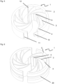
- the spacer 1 has an external frame 2 supporting a plurality of spring curved leaves 3.
- Each of the spring curved leaves 3 has a fixed end 4 attached to an inner face (or inner surface) of the external frame 2.
- Each spring curved leaf 3 further has a free end 5.
- the free ends 5 are arranged to flexibly wrap the first wire 101 as shown in figure 3 . That is, the free ends 5 of the spring curved leaves 3 defines a first wrapping portion 91, having a first diameter matching with the diameter of the first wire 101.
- the free ends 5 are represented in figure 3 in a first position. Each free end 5 is arranged to be in contact with the first wire 101. Thereby, a flexible support and wrapping is provided to the first wire 101.
- each spring curved leaf 3 extends at an oblique angle from the inner face of the external frame 2 and has a curvature such that the free end 5 of each curved leaf 3 is configured to contact the first wire 101 on a concave side of the curvature (or on a convex side of the curvature as illustrated in figure 8 ).
- the spring curved leaf 3 has an elongate shape with the fixed end 4, also called proximal portion, supported by the external frame and projecting inwardly (i.e. to an inside of the spacer 1), and with the free end 5, also called distal portion.
- the distal portion is provided with a contact surface (or a contact line) arranged to contact the first wire 101 and maintain it, in cooperation with the other contact surfaces of the other spring curved leaves 3.
- Figure 4 illustrates the spacer 1 according to the first embodiment with a second wire 102, which is an example of a second piece to be maintained.
- the second wire 102 is an example of wires 100, and may also be a bundle or a harness having the same shape of second wire 102.
- the free ends 5 of the spring curved leaves 3 defines a second wrapping portion 92, having a second diameter matching with the diameter of the second wire 102.
- the free ends 5 are represented in figure 4 in a second position. Each free end 5 is arranged to be in contact with the second wire 102.
- the diameter of the second wire 102 is greater than the diameter of the first wire 101 in the example shown in figures 3-4 .
- the free ends 5 are movable between :
- the first position corresponding to the first wrapping portion 91 may be considered as a rest position when no load is applied on the free ends 5 (and on the spring curved leaves 3), due to a nominal diameter corresponding to the first wire 101.
- the second position corresponding to the second wrapping portion 92 may be considered as a work position when a load is applied on the free ends 5 (and on the spring curved leaves 3), due to the diameter of the second wire 102 which is bigger than the nominal diameter.
- the spring curved leaves 5 allows for an improved flow resistance of the sealing material (e.g. polyurethane) when introduced in the mold 200, so as to facilitate the correct repartition of the sealing material in the mold 200 and improving the correct over molding of the wires 100.
- the sealing material e.g. polyurethane
- the fixed end 4 may be attached to the inner face of the external frame by a flexible anchoring portion, to further adjust and improve the flexibility of the spring curved leaves 3.
- Figure 5 illustrates the spacer 1 according to a second embodiment with a hinged portion 12, in an opened position.
- the wires 100 can be easily placed in the spacer 1, and the spacer 1 can be closed thereafter.
- the spacer 1 may have a lock portion having a hook 10 and a groove 11 arranged to retain the hook 10. Thereby, the spacer 1 can be maintained in a closed position and retain the wires 100.
- Figure 6 illustrates the spacer 1 according to a third embodiment with a groove 20 for a cable tie.
- the groove 20 may receive a cable tie (not shown) in order to fix the over molded wires 100 onto a support or the like, for final use of the wires 100.
- the groove 20 is preferably circumferential is order to receive the cable tie.
- the groove 20 is preferably placed on an outer surface of the external frame 2, the outer face being opposite to the inner face.
- FIG. 7 illustrates the spacer 1 according to a fourth embodiment with lock portions.
- the spacer 1 may have for example two lock portions having the grooves 11 and the hooks 10, so as to maintain the spacer 1 in the closed position.
- the grooves 11 are arranged to cooperate with the hooks 10 so as to maintain the spacer 1 in a closed position.
- Figure 8 illustrates the spacer 1 according to a fifth embodiment with a rectangular external frame 2 and outside pins 30.
- the rectangular external frame 2 is an example of external frame 2.
- the external frame 2 has outside pins 30.
- the outside pins 30 may be located in milled pockets of the mold 200 so as to better placed and locate the spacer 1 in the mold 200. Also, they can be used to create space for sealant to fully cover the outside face of the external frame.
- each spring curved leaf 3 extends at the oblique angle from the inner face of the external frame 2 and has the curvature such that the free end 5 of each curved leaf 3 is configured to contact the one or more pieces to be maintained 100, 101, 102 on a convex side of the curvature.
- the oblique angle may be adapted according to the configuration. That is, each of the spring curved leaves 3 has the curvature.
- the wrapping portion 93 is represented in figure 8 and is defined by external portions of the spring curved leaves 3, on an external side of their curvature, that is to say on the convex side of the curvature.
- the wrapping portions 91-92 are formed by internal portions of the spring curved leaves 3, on an internal side of their curvature, that is to say on their concave side.
- Figure 9 illustrates the spacer 1 according to a sixth embodiment with an oval shape.
- the spacer 1 has an oval shape so as to be adaptable to a desired shape of the over molded wires 100.
- the spacer 1 is also represented with the hook 10, the outside pins 30, the external frame 2 and the spring curved leaves 3.
- the spacer 1 according to the above embodiments also called fishbone inserts, are designed to ensure that the spacer 1 is suitable to accommodate differences in harness/wire diameters with constant outer diameter of the space, so as to match the mold cavity of the mold 200 and match the shape of the final product.
- the spacer 1 has a plurality of spring curved leaves (also called internal leaves) which are flexible and can bend accordingly to match the shape and size of harness/wire inside.
- the internal structure could also be shaped to fit a rectangular shape (as shown in figure 8 ) with spring like structures having the same final effect.
- outside walls of the spacer 1 i.e. external frame 2 are thick enough so as to keep their geometry and diameter constant.
- the spacer geometry can be adjusted according to the sealing final desired shape. The same applies for further consideration of the quantity and shapes of spring curved leaves 3 inside the spacer 1.
- sealing material e.g. polyurethane
- the sealing material can easily flow between them assuring correct filling of the mold 200 and stable molding process.
- the spacer 1 can be made from material compatible with the sealing material to ensure a good adherence.
- the sealing material is preferably polyurethane but can also be PVC, PA, TPU or any suitable material.
- the final product i.e. the one or more over molded wires / harnesses / bundle
- the final product i.e. the one or more over molded wires / harnesses / bundle
- the final product can be de-molded (i.e. removed from the mold 200).
Landscapes
- Engineering & Computer Science (AREA)
- Manufacturing & Machinery (AREA)
- Mechanical Engineering (AREA)
- Injection Moulding Of Plastics Or The Like (AREA)
- Moulds For Moulding Plastics Or The Like (AREA)
- Installation Of Indoor Wiring (AREA)
- Casting Or Compression Moulding Of Plastics Or The Like (AREA)
Abstract
Description
- The present disclosure relates to a spacer for maintaining one or more wires, or one or more harnesses, or bundles or generally speaking pieces to be maintained, in particular during molding process, and a method of manufacturing over molded wires. This is of interest in the automotive industry in particular.
- Highly resistant polyurethane foam sealing of single wires or wire bundles is a standard sealing for firewall grommets. Polyurethane foam can be used also for other applications, for example splice over molding, rigid wiring and ring terminal sealing cups.
- The common way of creating polyurethane product on wires harnesses is injection of polyurethane material into a mold (or mould) through which wire harness is passing.
- Nowadays, in wire / harness molding process, operators need to take extra care to manually shape the wire / wire harness in the mold to ensure that no wires are touching the mold. However, after the closing of the mold, there is no feedback or insurance that wires are still in the desired position. This has at least the following disadvantages: there is a risk of damaging the wires during the closing of the mold, there is difficulty to place the wire / harness and position it in the mold, there is a risk of visible wires after molding process on product surface, and there is a risk of short circuit.
- Customer-specific wiring harness production is bringing challenge which is wire harness diameter depended from the car specification ordered by the end customer. With high content wire harness, there is a risk that wires can touch the mold surface (i.e. cavity surface of the mold) which can lead to jeopardizing sealing capabilities of the overmolding part and to create the risk of shortcut. That is to say, the wire touching the mold surface is not fully covered by the polyurethane and thereby the wire is not fully over molded and badly protected.
- Additionally, there is a need to (over) mold very long components on the harness. This leads to the situation where a wire harness or generally speaking a piece to be maintained, under its own weight or due to geometry, can sag within the mold, thereby causing the same risk as described before. That is to say, the wire (or wire harness, or a part of the bundle) may fall down due to its own weight and touch the mold, so that said wire will not be correctly over molded by the sealing material (such as polyurethane), and thereby will be badly protected. The same situation may be caused by 3D shape of the product, like twisted S shape which even in vertical mold can cause issues (that is to say issues are not only due to gravity but also shapes of the parts). The document
GB2243254A - However, there is not the possibility of adjustment to a variety of cable diameters nor the possibility to correctly allow the molding of the sealing material therein, due to the plain shape and the sealing flow resistance.
- Therefore, there is a need for another kind of solution that is a good trade-off for overcoming the different drawbacks of the prior art.
- In particular, there is a need to solve the problems of decentralization of pieces to be maintained such as a wire harness within the mold during sealant (e.g. polyurethane) process, of wire harness sagging within the mold (especially with long and/or 3D products), and of minimum distance of harness to the mold and its effect on polyurethane over molding surface.
- The present disclosure concerns a spacer for maintaining one or more pieces during a molding process, the spacer having:
- an external frame, and
- a plurality of spring curved leaves,
- A leaf may be defined as a thin sheet or plate of any substance. That is, the spring curved leaf is a leaf which is curved, is flexible and allows for a spring effect (elastic return force). Flexible is to be understood as capable of movement, in contrast with the external frame which is rigid. What is to be understood by wrap may be to envelop and secure for transportation or storage, that is to say to embrace, to enfold, or to surround. A spacer is a device or piece used to create or maintain a desired amount of space, that is to say to maintain a distance between the one or more pieces to be maintained (e.g. wires) held by the spacer and the mold (in particular inner surface of the mold, that is to say in the mold cavity surface).
- This allows to provide an easier manufacturing of the spacer and the one or more pieces to be maintained (e.g. wires) to be over molded, in particular for easy installation on a wire harness (or harnesses, or wire(s)). An over molded wire or overmolded piece to be maintained, is understood as a wire or a piece to be maintained which is covered or surrounded by a sealing material, such as polyurethane. The one or more pieces to be maintained may be one or more wires. Instead of (electrical) wires, pneumatic tubes, fiber optics, and the like may also be present in the bundle or being even directly wrapped by the spacer, and are examples of pieces to be maintained (or clamped). That is, a wire is something (such as a thin plant stem) that is wirelike in a general meaning; or to be more specific, an electrical wire and the like.
- Further, this allows to provide a spacer, also called fishbone insert, which could be preinstalled on the piece(s) to be maintained, wire(s), or harness(es), to firstly ensure that all around the harness there is a minimum distance to the mold surface, to secondly eliminate harness sagging by supporting its weight, and thirdly ensure that harness routing passing the mold is substantially following nominal center line (in particular theoretical nominal center line designed by CAD, computer-aided design, e.g. 3D CAD). The spacer can be called a fishbone insert because it can be defined as a set or network of elongated components (like bones of a fish, corresponding to the spring curved leaves) having free ends and connected by fixed portions to a spine (corresponding to the external frame) being a skeleton or a structural framework.
- Still further, this allows to provide a spacer or fishbone insert designed to cover all harness diameters, in particular within a car project. This allows to be designed as a single piece component which can be simply clipped on the pieces to be maintained, on wire harness or a few-part component which can be assembled on the harness with usage of its own locks or additional component such as cable ties.
- That is, the spacer according to the present disclosure allows to provide a correct centralization of the pieces to be maintained (e.g. wire harness) inside the mold prior to injection process, to eliminate (limit, suppress or compensate) the wire harness sagging under its own weight, to eliminate (limit, suppress or compensate) wire harness sagging due to 3D shape of polyurethane component, and additional tension brought with this, to correct flow of polyurethane material to the wires, and to provide compatibility with polyurethane foam not to lower or decrease sealing function.
- The present disclosure significantly improves spacer and molding process, especially the part which is operator dependent and then completely random.
- The spacer according to the present disclosure thereby allows for an easier wire / harness placement in the mold, an easier spacer installation on the wire / harness, the elimination of loose wires which can be smashed during closing of the mold, the elimination of visible wire after the molding process, the elimination of short circuit risk due to wires visible on sealing material (such as polyurethane) product surface, and more flexibility in matter of processing different harness diameters.
- The spacer according to the present disclosure enables development of a completely new line of polyurethane composite products, which could be more compact as spacers eliminate the need to design with extra wall thickness in order to compensate harness or single wire displacement from the center line.
- Advantageously, the free ends are movable between :
- a first position so as to define a first wrapping portion, and
- at least a second position, different from the first position, so as to define a second wrapping portion.
- Advantageously, the first wrapping portion and the second wrapping portion are defined by a surface of the free end arranged to be in contact with the one or more pieces to be maintained (e.g. wires). That is, the first wrapping portion and the second wrapping portion can be a plurality of lines of contact (or surfaces or thin surfaces) of the free ends on the one or more wires. The difference between the first wrapping portion and the second wrapping portion is that they are placed in different diameters to allow different diameter of wires to be held in place.
- Advantageously, the first wrapping portion and the second wrapping portion are cavities receiving the one or more pieces to be maintained (e.g. wires).
- Advantageously, each free end is arranged to be in contact with the one or more pieces to be maintained.
- This allows to provide an improved support to the one or more wires, in particular to allow for a flexible support and an adjustment in case of introduction of wires of different diameters. That is, the spacer allows to receive wires of different diameters, or to better maintain a plurality of wires at the same time.
- Advantageously, the free ends extends inwardly.
- Advantageously, the spring curved leaves extend in a direction having a radial component and a tangential component.
- Advantageously, the external frame has an external surface (or external face) and a groove for a cable tie arranged on the external surface, preferably circumferentially.
- This allows to facilitate the fixation of the spacer holding the one or more wires with a cable tie.
- Advantageously, the spacer further has a hinged portion and a lock portion, preferably opposed to the hinged portion, and wherein the spacer is arranged to define :
- an opened position wherein the one or more pieces to be maintained can be introduced in the spacer, and
- a closed position wherein the one or more pieces to be maintained can be wrapped by the spacer at the level of the free ends.
- This allows to facilitate the manufacturing of the one or more over molded wires, in particular by facilitating the introduction of the one or more wires in the spacer so as to be held in place.
- Advantageously, the spacer further has at least one lock portion.
- This allows to provide a fixation system between two portions of the spacer, thereby facilitating the manufacturing.
- Advantageously, each spring curved leaf has a curvature with an internal curved portion and an external curved portion, and the plurality of spring curved leaves is arranged so as to contact the one or more pieces to be maintained on the internal curved portion or on the external curved portion.
- In other words, each spring curved leaf extends at an oblique angle from the inner face of the external frame and has a curvature such that the free end of each curved leaf is configured to contact the one or more pieces to be maintained on a concave side of the curvature or on a convex side of the curvature.
- This allows to improve the support of the one or more pieces to be maintained (e.g. wires).
- Advantageously, the external frame has at least one outside pin.
- This allows to improve the positioning of the spacer by locating the outside pin in a corresponding (milled) pocket of the mold. In another variant, the pin is only touching the cavity surface, assuring that no outer face of the insert is not visible, to allow to have more sealant on the outside for a better mechanical integrity. Advantageously, the spacer is made out of plastic or resin, and could be integrally formed.
- This allows to provide an easy manufacturing.
- A second aspect of the present disclosure concerns a method for over molding one or more pieces to be maintained, the method comprising the steps of:
- providing at least one spacer according to the first aspect,
- providing one or more pieces to be maintained (or one or more harnesses, or a bundle of these),
- installing in a mold the at least one spacer, and the one or more pieces to be maintained in contact with free ends of the spacer,
- injecting a sealing material, such as polyurethane, in the mold so as to over mold the one or more pieces to be maintained.
- This allows to facilitate the manufacturing and the over molding of one or more pieces to be maintained (e.g. wires). This also allows to have the above mentioned effects and advantages, as explained with respect to the first aspect.
- Advantageously, the method further has the step of:
- opening the mold so as to extract the one or more over molded pieces to be maintained.
- This allows to manufacture the one or more over molded wires and to extract it from the mold.
- Advantageously, the spacer has an external frame with at least one outside pin, and
the method further has the step of : - placing the at least one outside pin of the spacer in at least one pocket of the mold.
- This allows to provide an improvement of the localization of the spacer in the mold, so as to ensure the correct over molding of the one or more wires.
- Other features, purposes and advantages of the disclosure will become more explicit by means of reading the detailed statement of the nonrestrictive embodiments made with reference to the accompanying drawings
- [
fig. 1 ] illustrates a spacer according to a first embodiment with pieces to be maintained therein, in a mold, - [
fig. 2 ] illustrates the spacer according to the first embodiment, in another mold, - [
fig. 3 ] illustrates the spacer according to the first embodiment with a first wire therein, - [
fig. 4 ] illustrates the spacer according to the first embodiment with a second wire, - [
fig. 5 ] illustrates the spacer according to a second embodiment with a hinged portion, in an opened position, - [
fig. 6 ] illustrates the spacer according to a third embodiment with a groove for a cable tie, - [
fig. 7 ] illustrates the spacer according to a fourth embodiment with lock portions, - [
fig. 8 ] illustrates the spacer according to a fifth embodiment with a rectangular external frame and outside pins, - [
fig. 9 ] illustrates the spacer according to a sixth embodiment with oval shape. - The present disclosure relates to a spacer for allowing space between pieces to be maintained and a mold, in a molding process, so as to provide high quality over molding of the pieces.
-
Figure 1 illustrates threespacers 1 according to a first embodiment with pieces to be maintained 100 therein, in amold 200. In the present embodiment, the pieces to be maintained 100 may be wires. - The
mold 200 has anentry portion 201 and anexit portion 202. - Each
spacer 1 is positioned in themold 200. Thewires 100 are positioned inside eachspacer 1, and follow the path defined by both thespacers 1 and themold 200. - A sealing material, such as polyurethane (PUR), can be introduced in the
mold 200, in order to over mold the pieces to be maintained (e.g. wires) 100. Injection channel and air vents are not represented in the drawings. Themold 200 may be adapted for PUR foaming process or PUR potting process, in particular with respect toentry portion 201,exit portion 202, injection channel and air vents , and the like, as necessary. - That is, as the
spacers 1 allows to avoid that the pieces to be maintained (e.g. wires) 100 directly touch themold 200, the pieces to be maintained (e.g. wires) 100 can be entirely over molded and correctly protected, without any piece to be maintained (e.g. wire) 100 uncovered by the sealing material. -
Figure 2 illustrates thespacer 1 according to the first embodiment, in anothermold 200. Theother mold 200 has also theentry portion 201 and theexit portion 202. - The wires are examples of pieces to be maintained, and the description is generally applicable to any piece to be maintained.
- For sake of brevity, the term wire is used hereafter. The
spacer 1 maintains thewires 100 in a desired path, so that none of thewires 100 directly touch themold 200. Thereby, a correct over molding of thewires 100 is achieved. -
Figure 3 illustrates thespacer 1 according to the first embodiment with afirst wire 101 therein, which is an example of a first piece to be maintained. Thefirst wire 101 is an example ofwires 100, and may also be a bundle or a harness having the same shape offirst wire 101. - The
spacer 1 has anexternal frame 2 supporting a plurality of spring curved leaves 3. Each of the spring curved leaves 3 has a fixedend 4 attached to an inner face (or inner surface) of theexternal frame 2. Each spring curvedleaf 3 further has afree end 5. The free ends 5 are arranged to flexibly wrap thefirst wire 101 as shown infigure 3 . That is, the free ends 5 of the spring curved leaves 3 defines afirst wrapping portion 91, having a first diameter matching with the diameter of thefirst wire 101. The free ends 5 are represented infigure 3 in a first position. Eachfree end 5 is arranged to be in contact with thefirst wire 101. Thereby, a flexible support and wrapping is provided to thefirst wire 101. That is, each spring curvedleaf 3 extends at an oblique angle from the inner face of theexternal frame 2 and has a curvature such that thefree end 5 of eachcurved leaf 3 is configured to contact thefirst wire 101 on a concave side of the curvature (or on a convex side of the curvature as illustrated infigure 8 ). In other words, the spring curvedleaf 3 has an elongate shape with thefixed end 4, also called proximal portion, supported by the external frame and projecting inwardly (i.e. to an inside of the spacer 1), and with thefree end 5, also called distal portion. The distal portion is provided with a contact surface (or a contact line) arranged to contact thefirst wire 101 and maintain it, in cooperation with the other contact surfaces of the other spring curved leaves 3. -
Figure 4 illustrates thespacer 1 according to the first embodiment with asecond wire 102, which is an example of a second piece to be maintained. - The reference number are kept as far as possible with respect to the different figures.
- The
second wire 102 is an example ofwires 100, and may also be a bundle or a harness having the same shape ofsecond wire 102. - The free ends 5 of the spring curved leaves 3 defines a
second wrapping portion 92, having a second diameter matching with the diameter of thesecond wire 102. The free ends 5 are represented infigure 4 in a second position. Eachfree end 5 is arranged to be in contact with thesecond wire 102. The diameter of thesecond wire 102 is greater than the diameter of thefirst wire 101 in the example shown infigures 3-4 . - Thereby, a flexible support and wrapping is provided to the
second wire 102, with thesame spacer 1 as for thefirst wire 101 having a smaller diameter. - In other words, the free ends 5 are movable between :
- a first position so as to define the
first wrapping portion 91, and - the second position, different from the first position, so as to define the
second wrapping portion 92. - The first position corresponding to the
first wrapping portion 91 may be considered as a rest position when no load is applied on the free ends 5 (and on the spring curved leaves 3), due to a nominal diameter corresponding to thefirst wire 101. The second position corresponding to thesecond wrapping portion 92 may be considered as a work position when a load is applied on the free ends 5 (and on the spring curved leaves 3), due to the diameter of thesecond wire 102 which is bigger than the nominal diameter. - Further, the spring curved leaves 5 allows for an improved flow resistance of the sealing material (e.g. polyurethane) when introduced in the
mold 200, so as to facilitate the correct repartition of the sealing material in themold 200 and improving the correct over molding of thewires 100. - In an embodiment, it is to be noted that the
fixed end 4 may be attached to the inner face of the external frame by a flexible anchoring portion, to further adjust and improve the flexibility of the spring curved leaves 3. -
Figure 5 illustrates thespacer 1 according to a second embodiment with a hingedportion 12, in an opened position. - The reference number are kept as far as possible between the different figures and different embodiments.
- In the opened position, the
wires 100 can be easily placed in thespacer 1, and thespacer 1 can be closed thereafter. - The
spacer 1 may have a lock portion having ahook 10 and agroove 11 arranged to retain thehook 10. Thereby, thespacer 1 can be maintained in a closed position and retain thewires 100. -
Figure 6 illustrates thespacer 1 according to a third embodiment with agroove 20 for a cable tie. - That is, after the
wires 100 are being over molded with the sealing material, thegroove 20 may receive a cable tie (not shown) in order to fix the over moldedwires 100 onto a support or the like, for final use of thewires 100. Thegroove 20 is preferably circumferential is order to receive the cable tie. Thegroove 20 is preferably placed on an outer surface of theexternal frame 2, the outer face being opposite to the inner face. - In another aspect, it is possible to use the cable ties as a fixation method for the insert itself, to keep both half portion locked together on the harness, especially with a big harness inside
Figure 7 illustrates thespacer 1 according to a fourth embodiment with lock portions. - The
spacer 1 may have for example two lock portions having thegrooves 11 and thehooks 10, so as to maintain thespacer 1 in the closed position. Thegrooves 11 are arranged to cooperate with thehooks 10 so as to maintain thespacer 1 in a closed position.Figure 8 illustrates thespacer 1 according to a fifth embodiment with a rectangularexternal frame 2 and outside pins 30. - The rectangular
external frame 2 is an example ofexternal frame 2. - The
external frame 2 has outside pins 30. The outside pins 30 may be located in milled pockets of themold 200 so as to better placed and locate thespacer 1 in themold 200. Also, they can be used to create space for sealant to fully cover the outside face of the external frame. - As illustrated in
figure 8 , each spring curvedleaf 3 extends at the oblique angle from the inner face of theexternal frame 2 and has the curvature such that thefree end 5 of eachcurved leaf 3 is configured to contact the one or more pieces to be maintained 100, 101, 102 on a convex side of the curvature. This is to be compared withfigure 3 wherein the contact between the one or more pieces to be maintained 100, 101, 102 is on the concave side of the curvature. It is to be noted the oblique angle may be adapted according to the configuration. That is, each of the spring curved leaves 3 has the curvature. The wrappingportion 93 is represented infigure 8 and is defined by external portions of the spring curved leaves 3, on an external side of their curvature, that is to say on the convex side of the curvature. - In contrast, in
figures 3-7 , the wrapping portions 91-92 are formed by internal portions of the spring curved leaves 3, on an internal side of their curvature, that is to say on their concave side. -
Figure 9 illustrates thespacer 1 according to a sixth embodiment with an oval shape. - The
spacer 1 has an oval shape so as to be adaptable to a desired shape of the over moldedwires 100. - The
spacer 1 is also represented with thehook 10, the outside pins 30, theexternal frame 2 and the spring curved leaves 3. - That is, the
spacer 1 according to the above embodiments, also called fishbone inserts, are designed to ensure that thespacer 1 is suitable to accommodate differences in harness/wire diameters with constant outer diameter of the space, so as to match the mold cavity of themold 200 and match the shape of the final product. - The
spacer 1 has a plurality of spring curved leaves (also called internal leaves) which are flexible and can bend accordingly to match the shape and size of harness/wire inside. - It can also be applied on single wires or any other object to be over molded. The internal structure could also be shaped to fit a rectangular shape (as shown in
figure 8 ) with spring like structures having the same final effect. - Outside walls of the spacer 1 (i.e. external frame 2) are thick enough so as to keep their geometry and diameter constant.
- The spacer geometry can be adjusted according to the sealing final desired shape. The same applies for further consideration of the quantity and shapes of spring curved leaves 3 inside the
spacer 1. - Outside pins 30 are useful to:
- minimize spacer area which can be exposed on final sealing material product,
- protect the
spacer 1 from being covered by release agent present on the mold walls, - fix position between the
spacer 1 and the mold 200 (mold can be prepared with milled pockets in which those outside pins 30 can be registered to move forward with injection). - After closing the mold, injection of sealing material (e.g. polyurethane) is performed.
- Due to the spring curved leaves 3, the sealing material can easily flow between them assuring correct filling of the
mold 200 and stable molding process. - The
spacer 1 can be made from material compatible with the sealing material to ensure a good adherence. The sealing material is preferably polyurethane but can also be PVC, PA, TPU or any suitable material. - After the process, the final product (i.e. the one or more over molded wires / harnesses / bundle) can be de-molded (i.e. removed from the mold 200).
- It will be understood that various modifications and/or improvements obvious to the person skilled in the art may be made to the various embodiments of the disclosure described in the present description without departing from the scope of the disclosure defined by the appended claims. The different embodiments can be combined whenever possible.
wherein the free ends of the plurality of spring curved leaves are arranged to flexibly wrap the one or more pieces to be maintained.
Claims (11)
- A spacer (1) for maintaining one or more pieces (100, 101, 102) during a molding process, the spacer (1) having:- an external frame (2), and- a plurality of spring curved leaves (3),wherein each spring curved leaf (3) has a fixed end (4) attached to an inner face of the external frame (2) and a free end (5), and
wherein the free ends (5) of the plurality of spring curved leaves (3) are arranged to flexibly wrap the one or more pieces to be maintained (100, 101, 102). - The spacer (1) according to claim 1, wherein the free ends (5) are movable between :- a first position so as to define a first wrapping portion (91), and- at least a second position, different from the first position, so as to define a second wrapping portion (92).
- The spacer (1) according to any one of claims 1 to 2, wherein each free end (5) is arranged to be in contact with the one or more pieces to be maintained (100, 101, 102).
- The spacer (1) according to any one of claims 1 to 3, wherein the external frame (2) has an external surface and a groove (20) arranged circumferentially on the external surface.
- The spacer (1) according to any one of claims 1 to 4, wherein the spacer (1) further has a hinged portion (12) and a lock portion (10, 11) preferably opposed to the hinged portion (12), and
wherein the spacer (1) is arranged to define :- an opened position wherein the one or more pieces to be maintained (100, 101, 102) can be introduced in the spacer (1), and- a closed position wherein the one or more pieces to be maintained (100, 101, 102) can be wrapped by the spacer (1) at the level of the free ends (5). - The spacer according to any one of claims 1 to 4, wherein the spacer (1) further has at least one lock portion (10, 11).
- The spacer (1) according to any one of claims 1 to 6, wherein each spring curved leaf (3) extends at an oblique angle from the inner face of the external frame (2) and has a curvature such that the free end (5) of each curved leaf (3) is configured to contact the one or more pieces to be maintained (100, 101, 102) on a concave side of the curvature or on a convex side of the curvature.
- The spacer (1) according to any one of claims 1 to 6, wherein the external frame (2) has at least one outside pin (30).
- A method for over molding one or more pieces to be maintained (100, 101, 102), the method comprising the steps of:- providing at least one spacer (1) according to any one of the claims 1 to 8,- providing one or more pieces to be maintained (100, 101, 102),- installing in a mold (200) the at least one spacer (1), and the one or more pieces to be maintained (100, 101, 102) in contact with free ends (5) of the spacer (1),- injecting a sealing material, such as polyurethane, in the mold (200) so as to over mold the one or more pieces to be maintained (100, 101, 102).
- The method according to claim 9, further having the step of:- opening the mold (200) so as to extract the one or more over molded pieces to be maintained (100, 101, 102).
- The method according to any one of claims 9 to 10, whereinthe spacer (1) is according to claim 8, andthe method further comprises the step of :- placing the at least one outside pin (30) of the spacer (1) in at least one pocket of the mold (200).
Priority Applications (3)
| Application Number | Priority Date | Filing Date | Title |
|---|---|---|---|
| EP22177687.5A EP4289594B1 (en) | 2022-06-07 | 2022-06-07 | Spacer for harness bundle |
| US18/126,628 US12390966B2 (en) | 2022-06-07 | 2023-03-27 | Spacer for harness bundle |
| CN202310511307.7A CN117200098A (en) | 2022-06-07 | 2023-05-08 | Spacer for wire harness bundle |
Applications Claiming Priority (1)
| Application Number | Priority Date | Filing Date | Title |
|---|---|---|---|
| EP22177687.5A EP4289594B1 (en) | 2022-06-07 | 2022-06-07 | Spacer for harness bundle |
Publications (2)
| Publication Number | Publication Date |
|---|---|
| EP4289594A1 true EP4289594A1 (en) | 2023-12-13 |
| EP4289594B1 EP4289594B1 (en) | 2025-08-06 |
Family
ID=81984834
Family Applications (1)
| Application Number | Title | Priority Date | Filing Date |
|---|---|---|---|
| EP22177687.5A Active EP4289594B1 (en) | 2022-06-07 | 2022-06-07 | Spacer for harness bundle |
Country Status (3)
| Country | Link |
|---|---|
| US (1) | US12390966B2 (en) |
| EP (1) | EP4289594B1 (en) |
| CN (1) | CN117200098A (en) |
Citations (6)
| Publication number | Priority date | Publication date | Assignee | Title |
|---|---|---|---|---|
| GB2243254A (en) | 1990-04-14 | 1991-10-23 | Minnesota Mining & Mfg | Spacer for joint of two or more cables or cable cores |
| WO2001042055A1 (en) * | 1999-12-07 | 2001-06-14 | Lear Automotive (Eeds) Spain, S.L. | Method for injecting cable lead-throughs and centering/separating element to be used in said method |
| US9758114B1 (en) * | 2016-05-19 | 2017-09-12 | Delphi Technologies, Inc. | Wire harness assembly with a grommet having a wire spacing retainer and method for manufacturing same |
| US20190134873A1 (en) * | 2017-11-09 | 2019-05-09 | Leoni Kabel Gmbh | Method for overmolding at least one line |
| US20190161032A1 (en) * | 2016-05-09 | 2019-05-30 | Yazaki Systems Technologies Gmbh | Wiring harness, vehicle component, mold, mold system and method for manufacturing the wiring harness |
| DE102018220197B3 (en) * | 2018-11-23 | 2020-03-19 | Leoni Bordnetz-Systeme Gmbh | Spacer, jacketed cable bundle and method for producing a jacketed cable bundle |
Family Cites Families (5)
| Publication number | Priority date | Publication date | Assignee | Title |
|---|---|---|---|---|
| US2600111A (en) | 1946-02-08 | 1952-06-10 | Hans D Isenberg | Coaxial cable with spiral spacer |
| US3296688A (en) * | 1964-07-08 | 1967-01-10 | Minnesota Mining & Mfg | Adjustable centering spacer |
| US3361866A (en) * | 1965-04-09 | 1968-01-02 | Babigan Raymond | Electrical conductor containing an ionizable gas and radioactive material to ionize the gas |
| US4018978A (en) * | 1976-02-25 | 1977-04-19 | I-T-E Imperial Corporation | Orbital disc insulator for SF6 gas-insulated bus |
| EP3422369B1 (en) | 2017-06-30 | 2020-03-04 | ABB Power Grids Switzerland AG | A high voltage capacitive device |
-
2022
- 2022-06-07 EP EP22177687.5A patent/EP4289594B1/en active Active
-
2023
- 2023-03-27 US US18/126,628 patent/US12390966B2/en active Active
- 2023-05-08 CN CN202310511307.7A patent/CN117200098A/en active Pending
Patent Citations (6)
| Publication number | Priority date | Publication date | Assignee | Title |
|---|---|---|---|---|
| GB2243254A (en) | 1990-04-14 | 1991-10-23 | Minnesota Mining & Mfg | Spacer for joint of two or more cables or cable cores |
| WO2001042055A1 (en) * | 1999-12-07 | 2001-06-14 | Lear Automotive (Eeds) Spain, S.L. | Method for injecting cable lead-throughs and centering/separating element to be used in said method |
| US20190161032A1 (en) * | 2016-05-09 | 2019-05-30 | Yazaki Systems Technologies Gmbh | Wiring harness, vehicle component, mold, mold system and method for manufacturing the wiring harness |
| US9758114B1 (en) * | 2016-05-19 | 2017-09-12 | Delphi Technologies, Inc. | Wire harness assembly with a grommet having a wire spacing retainer and method for manufacturing same |
| US20190134873A1 (en) * | 2017-11-09 | 2019-05-09 | Leoni Kabel Gmbh | Method for overmolding at least one line |
| DE102018220197B3 (en) * | 2018-11-23 | 2020-03-19 | Leoni Bordnetz-Systeme Gmbh | Spacer, jacketed cable bundle and method for producing a jacketed cable bundle |
Also Published As
| Publication number | Publication date |
|---|---|
| US20230390982A1 (en) | 2023-12-07 |
| EP4289594B1 (en) | 2025-08-06 |
| US12390966B2 (en) | 2025-08-19 |
| CN117200098A (en) | 2023-12-08 |
Similar Documents
| Publication | Publication Date | Title |
|---|---|---|
| US6069319A (en) | Foamed-in harnesses | |
| US10103526B2 (en) | Protector and wire harness | |
| CN1155776A (en) | Wire bundle sealing system for bulkhead feedthroughs | |
| AU2011372146B2 (en) | Corrugated tube with route-maintaining member, and wire harness | |
| JP6608455B2 (en) | Seal mold split structure for combination cable and method for manufacturing the same | |
| CN110473665A (en) | Harness and its manufacturing method | |
| EP4289594A1 (en) | Spacer for harness bundle | |
| JP2015046969A (en) | Wire protection member | |
| CN110088852A (en) | Method and device for manufacturing a sheath for an electrical cable | |
| JP2024509402A (en) | Manufacturing molds, systems, and methods for manufacturing cable harnesses | |
| CN107210596A (en) | The method that the sealing molding segmenting structure of combination cable and the sealing for manufacturing combination cable mould segmenting structure | |
| EP0681303A1 (en) | Molded cabling and a method of production | |
| WO2015025893A1 (en) | External member and method for producing external member | |
| IE912988A1 (en) | Cable harness | |
| US11398325B2 (en) | Cable assembly with bundling arrangement | |
| US20240200711A1 (en) | Flexible Protection for Rigid Pipes | |
| JP2013005688A (en) | Wire harness with sheath material and manufacturing method thereof | |
| WO2012113809A1 (en) | Air blown optical fibre fixation | |
| US7963006B2 (en) | Retainer for overmolded electrical circuit | |
| JP7283921B2 (en) | wire harness | |
| JP5784902B2 (en) | Wire harness | |
| JP2004006126A (en) | Molded wire harness and molding die | |
| US12565161B2 (en) | Spacer | |
| JP2701155B2 (en) | Insert molding method | |
| JP2012133927A (en) | Manufacturing method of wiring harness and wiring harness |
Legal Events
| Date | Code | Title | Description |
|---|---|---|---|
| PUAI | Public reference made under article 153(3) epc to a published international application that has entered the european phase |
Free format text: ORIGINAL CODE: 0009012 |
|
| STAA | Information on the status of an ep patent application or granted ep patent |
Free format text: STATUS: THE APPLICATION HAS BEEN PUBLISHED |
|
| AK | Designated contracting states |
Kind code of ref document: A1 Designated state(s): AL AT BE BG CH CY CZ DE DK EE ES FI FR GB GR HR HU IE IS IT LI LT LU LV MC MK MT NL NO PL PT RO RS SE SI SK SM TR |
|
| STAA | Information on the status of an ep patent application or granted ep patent |
Free format text: STATUS: REQUEST FOR EXAMINATION WAS MADE |
|
| 17P | Request for examination filed |
Effective date: 20240416 |
|
| RBV | Designated contracting states (corrected) |
Designated state(s): AL AT BE BG CH CY CZ DE DK EE ES FI FR GB GR HR HU IE IS IT LI LT LU LV MC MK MT NL NO PL PT RO RS SE SI SK SM TR |
|
| RAP1 | Party data changed (applicant data changed or rights of an application transferred) |
Owner name: APTIV TECHNOLOGIES AG |
|
| GRAP | Despatch of communication of intention to grant a patent |
Free format text: ORIGINAL CODE: EPIDOSNIGR1 |
|
| STAA | Information on the status of an ep patent application or granted ep patent |
Free format text: STATUS: GRANT OF PATENT IS INTENDED |
|
| INTG | Intention to grant announced |
Effective date: 20250307 |
|
| RIC1 | Information provided on ipc code assigned before grant |
Ipc: H01B 13/012 20060101ALI20250228BHEP Ipc: B29L 31/34 20060101ALI20250228BHEP Ipc: B29K 75/00 20060101ALI20250228BHEP Ipc: B60R 16/02 20060101ALI20250228BHEP Ipc: B29C 45/14 20060101AFI20250228BHEP |
|
| GRAS | Grant fee paid |
Free format text: ORIGINAL CODE: EPIDOSNIGR3 |
|
| GRAA | (expected) grant |
Free format text: ORIGINAL CODE: 0009210 |
|
| STAA | Information on the status of an ep patent application or granted ep patent |
Free format text: STATUS: THE PATENT HAS BEEN GRANTED |
|
| AK | Designated contracting states |
Kind code of ref document: B1 Designated state(s): AL AT BE BG CH CY CZ DE DK EE ES FI FR GB GR HR HU IE IS IT LI LT LU LV MC MK MT NL NO PL PT RO RS SE SI SK SM TR |
|
| RAP3 | Party data changed (applicant data changed or rights of an application transferred) |
Owner name: APTIV TECHNOLOGIES AG |
|
| REG | Reference to a national code |
Ref country code: GB Ref legal event code: FG4D |
|
| REG | Reference to a national code |
Ref country code: CH Ref legal event code: EP |
|
| REG | Reference to a national code |
Ref country code: DE Ref legal event code: R096 Ref document number: 602022018755 Country of ref document: DE |
|
| REG | Reference to a national code |
Ref country code: IE Ref legal event code: FG4D |
|
| P01 | Opt-out of the competence of the unified patent court (upc) registered |
Free format text: CASE NUMBER: UPC_APP_8662_4289594/2025 Effective date: 20251001 |
|
| REG | Reference to a national code |
Ref country code: NL Ref legal event code: MP Effective date: 20250806 |
|
| PG25 | Lapsed in a contracting state [announced via postgrant information from national office to epo] |
Ref country code: IS Free format text: LAPSE BECAUSE OF FAILURE TO SUBMIT A TRANSLATION OF THE DESCRIPTION OR TO PAY THE FEE WITHIN THE PRESCRIBED TIME-LIMIT Effective date: 20251206 |
|
| PG25 | Lapsed in a contracting state [announced via postgrant information from national office to epo] |
Ref country code: NO Free format text: LAPSE BECAUSE OF FAILURE TO SUBMIT A TRANSLATION OF THE DESCRIPTION OR TO PAY THE FEE WITHIN THE PRESCRIBED TIME-LIMIT Effective date: 20251106 |
|
| REG | Reference to a national code |
Ref country code: LT Ref legal event code: MG9D |
|
| PG25 | Lapsed in a contracting state [announced via postgrant information from national office to epo] |
Ref country code: PT Free format text: LAPSE BECAUSE OF FAILURE TO SUBMIT A TRANSLATION OF THE DESCRIPTION OR TO PAY THE FEE WITHIN THE PRESCRIBED TIME-LIMIT Effective date: 20251209 |
|
| PG25 | Lapsed in a contracting state [announced via postgrant information from national office to epo] |
Ref country code: FI Free format text: LAPSE BECAUSE OF FAILURE TO SUBMIT A TRANSLATION OF THE DESCRIPTION OR TO PAY THE FEE WITHIN THE PRESCRIBED TIME-LIMIT Effective date: 20250806 |
|
| PG25 | Lapsed in a contracting state [announced via postgrant information from national office to epo] |
Ref country code: NL Free format text: LAPSE BECAUSE OF FAILURE TO SUBMIT A TRANSLATION OF THE DESCRIPTION OR TO PAY THE FEE WITHIN THE PRESCRIBED TIME-LIMIT Effective date: 20250806 Ref country code: HR Free format text: LAPSE BECAUSE OF FAILURE TO SUBMIT A TRANSLATION OF THE DESCRIPTION OR TO PAY THE FEE WITHIN THE PRESCRIBED TIME-LIMIT Effective date: 20250806 |
|
| PG25 | Lapsed in a contracting state [announced via postgrant information from national office to epo] |
Ref country code: GR Free format text: LAPSE BECAUSE OF FAILURE TO SUBMIT A TRANSLATION OF THE DESCRIPTION OR TO PAY THE FEE WITHIN THE PRESCRIBED TIME-LIMIT Effective date: 20251107 |
|
| PG25 | Lapsed in a contracting state [announced via postgrant information from national office to epo] |
Ref country code: SE Free format text: LAPSE BECAUSE OF FAILURE TO SUBMIT A TRANSLATION OF THE DESCRIPTION OR TO PAY THE FEE WITHIN THE PRESCRIBED TIME-LIMIT Effective date: 20250806 |
|
| PG25 | Lapsed in a contracting state [announced via postgrant information from national office to epo] |
Ref country code: LV Free format text: LAPSE BECAUSE OF FAILURE TO SUBMIT A TRANSLATION OF THE DESCRIPTION OR TO PAY THE FEE WITHIN THE PRESCRIBED TIME-LIMIT Effective date: 20250806 |
|
| PG25 | Lapsed in a contracting state [announced via postgrant information from national office to epo] |
Ref country code: PL Free format text: LAPSE BECAUSE OF FAILURE TO SUBMIT A TRANSLATION OF THE DESCRIPTION OR TO PAY THE FEE WITHIN THE PRESCRIBED TIME-LIMIT Effective date: 20250806 Ref country code: BG Free format text: LAPSE BECAUSE OF FAILURE TO SUBMIT A TRANSLATION OF THE DESCRIPTION OR TO PAY THE FEE WITHIN THE PRESCRIBED TIME-LIMIT Effective date: 20250806 |
|
| PG25 | Lapsed in a contracting state [announced via postgrant information from national office to epo] |
Ref country code: RS Free format text: LAPSE BECAUSE OF FAILURE TO SUBMIT A TRANSLATION OF THE DESCRIPTION OR TO PAY THE FEE WITHIN THE PRESCRIBED TIME-LIMIT Effective date: 20251106 |
|
| PG25 | Lapsed in a contracting state [announced via postgrant information from national office to epo] |
Ref country code: ES Free format text: LAPSE BECAUSE OF FAILURE TO SUBMIT A TRANSLATION OF THE DESCRIPTION OR TO PAY THE FEE WITHIN THE PRESCRIBED TIME-LIMIT Effective date: 20250806 |
|
| REG | Reference to a national code |
Ref country code: AT Ref legal event code: MK05 Ref document number: 1821329 Country of ref document: AT Kind code of ref document: T Effective date: 20250806 |
|
| PG25 | Lapsed in a contracting state [announced via postgrant information from national office to epo] |
Ref country code: SM Free format text: LAPSE BECAUSE OF FAILURE TO SUBMIT A TRANSLATION OF THE DESCRIPTION OR TO PAY THE FEE WITHIN THE PRESCRIBED TIME-LIMIT Effective date: 20250806 |
|
| PG25 | Lapsed in a contracting state [announced via postgrant information from national office to epo] |
Ref country code: DK Free format text: LAPSE BECAUSE OF FAILURE TO SUBMIT A TRANSLATION OF THE DESCRIPTION OR TO PAY THE FEE WITHIN THE PRESCRIBED TIME-LIMIT Effective date: 20250806 |
|
| PG25 | Lapsed in a contracting state [announced via postgrant information from national office to epo] |
Ref country code: AT Free format text: LAPSE BECAUSE OF FAILURE TO SUBMIT A TRANSLATION OF THE DESCRIPTION OR TO PAY THE FEE WITHIN THE PRESCRIBED TIME-LIMIT Effective date: 20250806 |
|
| PG25 | Lapsed in a contracting state [announced via postgrant information from national office to epo] |
Ref country code: IT Free format text: LAPSE BECAUSE OF FAILURE TO SUBMIT A TRANSLATION OF THE DESCRIPTION OR TO PAY THE FEE WITHIN THE PRESCRIBED TIME-LIMIT Effective date: 20250806 |
|
| PG25 | Lapsed in a contracting state [announced via postgrant information from national office to epo] |
Ref country code: CZ Free format text: LAPSE BECAUSE OF FAILURE TO SUBMIT A TRANSLATION OF THE DESCRIPTION OR TO PAY THE FEE WITHIN THE PRESCRIBED TIME-LIMIT Effective date: 20250806 |
|
| PG25 | Lapsed in a contracting state [announced via postgrant information from national office to epo] |
Ref country code: EE Free format text: LAPSE BECAUSE OF FAILURE TO SUBMIT A TRANSLATION OF THE DESCRIPTION OR TO PAY THE FEE WITHIN THE PRESCRIBED TIME-LIMIT Effective date: 20250806 Ref country code: SK Free format text: LAPSE BECAUSE OF FAILURE TO SUBMIT A TRANSLATION OF THE DESCRIPTION OR TO PAY THE FEE WITHIN THE PRESCRIBED TIME-LIMIT Effective date: 20250806 |