EP4289583A1 - Extrusion device, and method for manufacturing resin product - Google Patents
Extrusion device, and method for manufacturing resin product Download PDFInfo
- Publication number
- EP4289583A1 EP4289583A1 EP21924760.8A EP21924760A EP4289583A1 EP 4289583 A1 EP4289583 A1 EP 4289583A1 EP 21924760 A EP21924760 A EP 21924760A EP 4289583 A1 EP4289583 A1 EP 4289583A1
- Authority
- EP
- European Patent Office
- Prior art keywords
- molten resin
- die
- resin
- pressure
- cylinder
- Prior art date
- Legal status (The legal status is an assumption and is not a legal conclusion. Google has not performed a legal analysis and makes no representation as to the accuracy of the status listed.)
- Pending
Links
Images




Classifications
-
- B—PERFORMING OPERATIONS; TRANSPORTING
- B29—WORKING OF PLASTICS; WORKING OF SUBSTANCES IN A PLASTIC STATE IN GENERAL
- B29B—PREPARATION OR PRETREATMENT OF THE MATERIAL TO BE SHAPED; MAKING GRANULES OR PREFORMS; RECOVERY OF PLASTICS OR OTHER CONSTITUENTS OF WASTE MATERIAL CONTAINING PLASTICS
- B29B7/00—Mixing; Kneading
- B29B7/30—Mixing; Kneading continuous, with mechanical mixing or kneading devices
- B29B7/58—Component parts, details or accessories; Auxiliary operations
- B29B7/582—Component parts, details or accessories; Auxiliary operations for discharging, e.g. doors
-
- B—PERFORMING OPERATIONS; TRANSPORTING
- B29—WORKING OF PLASTICS; WORKING OF SUBSTANCES IN A PLASTIC STATE IN GENERAL
- B29B—PREPARATION OR PRETREATMENT OF THE MATERIAL TO BE SHAPED; MAKING GRANULES OR PREFORMS; RECOVERY OF PLASTICS OR OTHER CONSTITUENTS OF WASTE MATERIAL CONTAINING PLASTICS
- B29B7/00—Mixing; Kneading
- B29B7/30—Mixing; Kneading continuous, with mechanical mixing or kneading devices
- B29B7/58—Component parts, details or accessories; Auxiliary operations
- B29B7/72—Measuring, controlling or regulating
- B29B7/726—Measuring properties of mixture, e.g. temperature or density
-
- B—PERFORMING OPERATIONS; TRANSPORTING
- B29—WORKING OF PLASTICS; WORKING OF SUBSTANCES IN A PLASTIC STATE IN GENERAL
- B29B—PREPARATION OR PRETREATMENT OF THE MATERIAL TO BE SHAPED; MAKING GRANULES OR PREFORMS; RECOVERY OF PLASTICS OR OTHER CONSTITUENTS OF WASTE MATERIAL CONTAINING PLASTICS
- B29B7/00—Mixing; Kneading
- B29B7/30—Mixing; Kneading continuous, with mechanical mixing or kneading devices
- B29B7/58—Component parts, details or accessories; Auxiliary operations
- B29B7/72—Measuring, controlling or regulating
- B29B7/728—Measuring data of the driving system, e.g. torque, speed, power, vibration
-
- B—PERFORMING OPERATIONS; TRANSPORTING
- B29—WORKING OF PLASTICS; WORKING OF SUBSTANCES IN A PLASTIC STATE IN GENERAL
- B29B—PREPARATION OR PRETREATMENT OF THE MATERIAL TO BE SHAPED; MAKING GRANULES OR PREFORMS; RECOVERY OF PLASTICS OR OTHER CONSTITUENTS OF WASTE MATERIAL CONTAINING PLASTICS
- B29B7/00—Mixing; Kneading
- B29B7/80—Component parts, details or accessories; Auxiliary operations
- B29B7/88—Adding charges, i.e. additives
-
- B—PERFORMING OPERATIONS; TRANSPORTING
- B29—WORKING OF PLASTICS; WORKING OF SUBSTANCES IN A PLASTIC STATE IN GENERAL
- B29B—PREPARATION OR PRETREATMENT OF THE MATERIAL TO BE SHAPED; MAKING GRANULES OR PREFORMS; RECOVERY OF PLASTICS OR OTHER CONSTITUENTS OF WASTE MATERIAL CONTAINING PLASTICS
- B29B9/00—Making granules
- B29B9/02—Making granules by dividing preformed material
- B29B9/06—Making granules by dividing preformed material in the form of filamentary material, e.g. combined with extrusion
-
- B—PERFORMING OPERATIONS; TRANSPORTING
- B29—WORKING OF PLASTICS; WORKING OF SUBSTANCES IN A PLASTIC STATE IN GENERAL
- B29B—PREPARATION OR PRETREATMENT OF THE MATERIAL TO BE SHAPED; MAKING GRANULES OR PREFORMS; RECOVERY OF PLASTICS OR OTHER CONSTITUENTS OF WASTE MATERIAL CONTAINING PLASTICS
- B29B9/00—Making granules
- B29B9/12—Making granules characterised by structure or composition
-
- B—PERFORMING OPERATIONS; TRANSPORTING
- B29—WORKING OF PLASTICS; WORKING OF SUBSTANCES IN A PLASTIC STATE IN GENERAL
- B29C—SHAPING OR JOINING OF PLASTICS; SHAPING OF MATERIAL IN A PLASTIC STATE, NOT OTHERWISE PROVIDED FOR; AFTER-TREATMENT OF THE SHAPED PRODUCTS, e.g. REPAIRING
- B29C48/00—Extrusion moulding, i.e. expressing the moulding material through a die or nozzle which imparts the desired form; Apparatus therefor
- B29C48/03—Extrusion moulding, i.e. expressing the moulding material through a die or nozzle which imparts the desired form; Apparatus therefor characterised by the shape of the extruded material at extrusion
- B29C48/05—Filamentary, e.g. strands
-
- B—PERFORMING OPERATIONS; TRANSPORTING
- B29—WORKING OF PLASTICS; WORKING OF SUBSTANCES IN A PLASTIC STATE IN GENERAL
- B29C—SHAPING OR JOINING OF PLASTICS; SHAPING OF MATERIAL IN A PLASTIC STATE, NOT OTHERWISE PROVIDED FOR; AFTER-TREATMENT OF THE SHAPED PRODUCTS, e.g. REPAIRING
- B29C48/00—Extrusion moulding, i.e. expressing the moulding material through a die or nozzle which imparts the desired form; Apparatus therefor
- B29C48/25—Component parts, details or accessories; Auxiliary operations
- B29C48/30—Extrusion nozzles or dies
- B29C48/345—Extrusion nozzles comprising two or more adjacently arranged ports, for simultaneously extruding multiple strands, e.g. for pelletising
-
- B—PERFORMING OPERATIONS; TRANSPORTING
- B29—WORKING OF PLASTICS; WORKING OF SUBSTANCES IN A PLASTIC STATE IN GENERAL
- B29C—SHAPING OR JOINING OF PLASTICS; SHAPING OF MATERIAL IN A PLASTIC STATE, NOT OTHERWISE PROVIDED FOR; AFTER-TREATMENT OF THE SHAPED PRODUCTS, e.g. REPAIRING
- B29C48/00—Extrusion moulding, i.e. expressing the moulding material through a die or nozzle which imparts the desired form; Apparatus therefor
- B29C48/25—Component parts, details or accessories; Auxiliary operations
- B29C48/36—Means for plasticising or homogenising the moulding material or forcing it through the nozzle or die
- B29C48/50—Details of extruders
- B29C48/68—Barrels or cylinders
-
- B—PERFORMING OPERATIONS; TRANSPORTING
- B29—WORKING OF PLASTICS; WORKING OF SUBSTANCES IN A PLASTIC STATE IN GENERAL
- B29C—SHAPING OR JOINING OF PLASTICS; SHAPING OF MATERIAL IN A PLASTIC STATE, NOT OTHERWISE PROVIDED FOR; AFTER-TREATMENT OF THE SHAPED PRODUCTS, e.g. REPAIRING
- B29C48/00—Extrusion moulding, i.e. expressing the moulding material through a die or nozzle which imparts the desired form; Apparatus therefor
- B29C48/25—Component parts, details or accessories; Auxiliary operations
- B29C48/36—Means for plasticising or homogenising the moulding material or forcing it through the nozzle or die
- B29C48/50—Details of extruders
- B29C48/69—Filters or screens for the moulding material
-
- B—PERFORMING OPERATIONS; TRANSPORTING
- B29—WORKING OF PLASTICS; WORKING OF SUBSTANCES IN A PLASTIC STATE IN GENERAL
- B29C—SHAPING OR JOINING OF PLASTICS; SHAPING OF MATERIAL IN A PLASTIC STATE, NOT OTHERWISE PROVIDED FOR; AFTER-TREATMENT OF THE SHAPED PRODUCTS, e.g. REPAIRING
- B29C48/00—Extrusion moulding, i.e. expressing the moulding material through a die or nozzle which imparts the desired form; Apparatus therefor
- B29C48/25—Component parts, details or accessories; Auxiliary operations
- B29C48/36—Means for plasticising or homogenising the moulding material or forcing it through the nozzle or die
- B29C48/50—Details of extruders
- B29C48/695—Flow dividers, e.g. breaker plates
-
- B—PERFORMING OPERATIONS; TRANSPORTING
- B29—WORKING OF PLASTICS; WORKING OF SUBSTANCES IN A PLASTIC STATE IN GENERAL
- B29C—SHAPING OR JOINING OF PLASTICS; SHAPING OF MATERIAL IN A PLASTIC STATE, NOT OTHERWISE PROVIDED FOR; AFTER-TREATMENT OF THE SHAPED PRODUCTS, e.g. REPAIRING
- B29C48/00—Extrusion moulding, i.e. expressing the moulding material through a die or nozzle which imparts the desired form; Apparatus therefor
- B29C48/25—Component parts, details or accessories; Auxiliary operations
- B29C48/92—Measuring, controlling or regulating
-
- G—PHYSICS
- G01—MEASURING; TESTING
- G01N—INVESTIGATING OR ANALYSING MATERIALS BY DETERMINING THEIR CHEMICAL OR PHYSICAL PROPERTIES
- G01N11/00—Investigating flow properties of materials, e.g. viscosity, plasticity; Analysing materials by determining flow properties
- G01N11/02—Investigating flow properties of materials, e.g. viscosity, plasticity; Analysing materials by determining flow properties by measuring flow of the material
- G01N11/04—Investigating flow properties of materials, e.g. viscosity, plasticity; Analysing materials by determining flow properties by measuring flow of the material through a restricted passage, e.g. tube, aperture
- G01N11/08—Investigating flow properties of materials, e.g. viscosity, plasticity; Analysing materials by determining flow properties by measuring flow of the material through a restricted passage, e.g. tube, aperture by measuring pressure required to produce a known flow
-
- B—PERFORMING OPERATIONS; TRANSPORTING
- B29—WORKING OF PLASTICS; WORKING OF SUBSTANCES IN A PLASTIC STATE IN GENERAL
- B29B—PREPARATION OR PRETREATMENT OF THE MATERIAL TO BE SHAPED; MAKING GRANULES OR PREFORMS; RECOVERY OF PLASTICS OR OTHER CONSTITUENTS OF WASTE MATERIAL CONTAINING PLASTICS
- B29B7/00—Mixing; Kneading
- B29B7/30—Mixing; Kneading continuous, with mechanical mixing or kneading devices
- B29B7/34—Mixing; Kneading continuous, with mechanical mixing or kneading devices with movable mixing or kneading devices
- B29B7/38—Mixing; Kneading continuous, with mechanical mixing or kneading devices with movable mixing or kneading devices rotary
- B29B7/46—Mixing; Kneading continuous, with mechanical mixing or kneading devices with movable mixing or kneading devices rotary with more than one shaft
- B29B7/48—Mixing; Kneading continuous, with mechanical mixing or kneading devices with movable mixing or kneading devices rotary with more than one shaft with intermeshing devices, e.g. screws
-
- B—PERFORMING OPERATIONS; TRANSPORTING
- B29—WORKING OF PLASTICS; WORKING OF SUBSTANCES IN A PLASTIC STATE IN GENERAL
- B29C—SHAPING OR JOINING OF PLASTICS; SHAPING OF MATERIAL IN A PLASTIC STATE, NOT OTHERWISE PROVIDED FOR; AFTER-TREATMENT OF THE SHAPED PRODUCTS, e.g. REPAIRING
- B29C2948/00—Indexing scheme relating to extrusion moulding
- B29C2948/92—Measuring, controlling or regulating
- B29C2948/92009—Measured parameter
- B29C2948/92019—Pressure
-
- B—PERFORMING OPERATIONS; TRANSPORTING
- B29—WORKING OF PLASTICS; WORKING OF SUBSTANCES IN A PLASTIC STATE IN GENERAL
- B29C—SHAPING OR JOINING OF PLASTICS; SHAPING OF MATERIAL IN A PLASTIC STATE, NOT OTHERWISE PROVIDED FOR; AFTER-TREATMENT OF THE SHAPED PRODUCTS, e.g. REPAIRING
- B29C2948/00—Indexing scheme relating to extrusion moulding
- B29C2948/92—Measuring, controlling or regulating
- B29C2948/92009—Measured parameter
- B29C2948/922—Viscosity; Melt flow index [MFI]; Molecular weight
-
- B—PERFORMING OPERATIONS; TRANSPORTING
- B29—WORKING OF PLASTICS; WORKING OF SUBSTANCES IN A PLASTIC STATE IN GENERAL
- B29C—SHAPING OR JOINING OF PLASTICS; SHAPING OF MATERIAL IN A PLASTIC STATE, NOT OTHERWISE PROVIDED FOR; AFTER-TREATMENT OF THE SHAPED PRODUCTS, e.g. REPAIRING
- B29C2948/00—Indexing scheme relating to extrusion moulding
- B29C2948/92—Measuring, controlling or regulating
- B29C2948/92323—Location or phase of measurement
- B29C2948/92361—Extrusion unit
- B29C2948/9238—Feeding, melting, plasticising or pumping zones, e.g. the melt itself
- B29C2948/924—Barrel or housing
-
- B—PERFORMING OPERATIONS; TRANSPORTING
- B29—WORKING OF PLASTICS; WORKING OF SUBSTANCES IN A PLASTIC STATE IN GENERAL
- B29C—SHAPING OR JOINING OF PLASTICS; SHAPING OF MATERIAL IN A PLASTIC STATE, NOT OTHERWISE PROVIDED FOR; AFTER-TREATMENT OF THE SHAPED PRODUCTS, e.g. REPAIRING
- B29C2948/00—Indexing scheme relating to extrusion moulding
- B29C2948/92—Measuring, controlling or regulating
- B29C2948/92323—Location or phase of measurement
- B29C2948/92361—Extrusion unit
- B29C2948/92409—Die; Nozzle zone
-
- B—PERFORMING OPERATIONS; TRANSPORTING
- B29—WORKING OF PLASTICS; WORKING OF SUBSTANCES IN A PLASTIC STATE IN GENERAL
- B29C—SHAPING OR JOINING OF PLASTICS; SHAPING OF MATERIAL IN A PLASTIC STATE, NOT OTHERWISE PROVIDED FOR; AFTER-TREATMENT OF THE SHAPED PRODUCTS, e.g. REPAIRING
- B29C2948/00—Indexing scheme relating to extrusion moulding
- B29C2948/92—Measuring, controlling or regulating
- B29C2948/92504—Controlled parameter
- B29C2948/92695—Viscosity; Melt flow index [MFI]; Molecular weight
-
- B—PERFORMING OPERATIONS; TRANSPORTING
- B29—WORKING OF PLASTICS; WORKING OF SUBSTANCES IN A PLASTIC STATE IN GENERAL
- B29C—SHAPING OR JOINING OF PLASTICS; SHAPING OF MATERIAL IN A PLASTIC STATE, NOT OTHERWISE PROVIDED FOR; AFTER-TREATMENT OF THE SHAPED PRODUCTS, e.g. REPAIRING
- B29C2948/00—Indexing scheme relating to extrusion moulding
- B29C2948/92—Measuring, controlling or regulating
- B29C2948/92819—Location or phase of control
- B29C2948/92857—Extrusion unit
- B29C2948/92876—Feeding, melting, plasticising or pumping zones, e.g. the melt itself
-
- B—PERFORMING OPERATIONS; TRANSPORTING
- B29—WORKING OF PLASTICS; WORKING OF SUBSTANCES IN A PLASTIC STATE IN GENERAL
- B29C—SHAPING OR JOINING OF PLASTICS; SHAPING OF MATERIAL IN A PLASTIC STATE, NOT OTHERWISE PROVIDED FOR; AFTER-TREATMENT OF THE SHAPED PRODUCTS, e.g. REPAIRING
- B29C2948/00—Indexing scheme relating to extrusion moulding
- B29C2948/92—Measuring, controlling or regulating
- B29C2948/92819—Location or phase of control
- B29C2948/92857—Extrusion unit
- B29C2948/92876—Feeding, melting, plasticising or pumping zones, e.g. the melt itself
- B29C2948/92895—Barrel or housing
-
- B—PERFORMING OPERATIONS; TRANSPORTING
- B29—WORKING OF PLASTICS; WORKING OF SUBSTANCES IN A PLASTIC STATE IN GENERAL
- B29C—SHAPING OR JOINING OF PLASTICS; SHAPING OF MATERIAL IN A PLASTIC STATE, NOT OTHERWISE PROVIDED FOR; AFTER-TREATMENT OF THE SHAPED PRODUCTS, e.g. REPAIRING
- B29C2948/00—Indexing scheme relating to extrusion moulding
- B29C2948/92—Measuring, controlling or regulating
- B29C2948/92819—Location or phase of control
- B29C2948/92857—Extrusion unit
- B29C2948/92904—Die; Nozzle zone
Definitions
- the present invention relates to an extruder and a method of manufacturing a resin product.
- Patent Document 1 Japanese Unexamined Patent Application Publication No. 2016-7819 describes a technique related to a strand manufacturing apparatus including an extruder.
- Patent Document 1 Japanese Unexamined Patent Application Publication No. 2016-7819
- an extruder includes a cylinder, a die having a hole to discharge a molten resin, a pressure measurement unit configured to measure a pressure of the molten resin in the cylinder or the die, and a calculation unit configured to calculate a viscosity of the molten resin based on a measured value of the pressure measurement unit.
- a method of manufacturing a resin product includes a step of (a) preparing an extruder including a cylinder and a die attached to the cylinder and a step of (b) supplying a resin material into the cylinder to form a molten resin and discharging the molten resin from a hole of the die.
- the method of manufacturing a resin product further includes a step of (c) measuring a pressure of the molten resin in the cylinder or the die and a step of (d) calculating a viscosity of the molten resin based on the pressure of the molten resin measured in the step (c).
- FIG. 1 is an explanatory diagram (side view) showing a configuration example of a pellet manufacturing system (pellet manufacturing apparatus) 12 using an extruder (extrusion molding machine) 1 according to the present embodiment.
- the extruder 1 shown in FIG. 1 includes a cylinder (barrel) 2, two screws 17 rotatably (freely rotatably) arranged in the cylinder 2, a rotary drive mechanism 3 for rotating the screws 17 in the cylinder 2, a hopper (resin input unit) 4 arranged on the upstream side (rear end side) of the cylinder 2, a die (mold) 5 attached to the downstream end of the cylinder 2, and an operation panel (operation unit, operation console) 6.
- the hopper 4 is connected to an upper surface of the cylinder 2, and a resin can be supplied into the cylinder 2 through the hopper 4.
- the temperature of the cylinder 2 is controlled by a temperature adjusting unit (temperature adjusting mechanism) (not shown) such as a heater.
- the extruder 1 may further include a filler feeder (not shown) connected to the cylinder 2, and in such a case, desired filler can be fed into the cylinder 2 from the filler feeder.
- the "downstream side” and “upstream side” means the downstream side of the resin flow in the extruder 1
- the "upstream side” means the upstream side of the resin flow in the extruder 1. Therefore, in the extruder 1, the side closer to a plurality of holes 21 of the die 5 described later is the downstream side, and the side farther from the plurality of holes 21 of the die 5, that is, the side closer to the hopper 4 is the upstream side.
- the two screws 17 are rotatably (freely rotatably) inserted and incorporated inside the cylinder 2. Therefore, the extruder 1 can be regarded also as a twin-screw extruder (twin-screw extrusion machine).
- the two screws 17 are arranged so as to mesh with each other and rotated in the cylinder 2.
- the longitudinal direction (long side direction, axial direction, extending direction) of the cylinder 2 and the longitudinal direction (long side direction, axial direction, extending direction) of the screws in the cylinder 2 are the same.
- the case where the number of screws 17 in the cylinder 2 is two is described, but the number of screws 17 in the cylinder 2 may be one as another aspect.
- the spatial volume can be increased when the number of screws 17 in the cylinder 2 is two, the supply capacity of the raw material can be increased in the case of double screws (two screws 17) as compared with the case of single screw (one screw 17) if the diameter of the screw is the same.
- the die 5 can function to discharge a molten resin extruded from the cylinder 2 of the extruder 1 while shaping it into a predetermined cross-sectional shape (here, string-like shape). Therefore, the die 5 is a die (mold) for extrusion molding.
- melting is not limited to melting with heat, but includes melting with a solvent or the like.
- the case of melting a resin with a solvent the case of melting a resin with microwaves, and the like may also be included in the "molten resin” in addition to the case of melting a resin by heating.
- liquid resin may also be included in the "molten resin”.
- the operation panel 6 includes a display unit 7 and an input unit 8.
- the input unit 8 includes, for example, a keyboard, switches, dials, buttons, a touch panel, and the like for use in input.
- the operation of the extruder 1 can be controlled by inputting commands, data, and the like necessary for operating the extruder 1 into the input unit 8.
- the display unit 7 can display, for example, information input to the input unit 8, information related to the operation and state of the extruder 1, and the like.
- the operation panel 6 includes a control unit 9 that controls the operation of the extruder 1.
- the control unit 9 controls the operation of the extruder 1 in accordance with commands, data, and the like input to the input unit 8.
- the control unit 9 can be configured by a computer including, for example, a semiconductor chip for control (semiconductor processor) and a semiconductor chip for storage (memory chip).
- control unit 9 includes a calculation unit 10 that calculates the viscosity of the molten resin based on the measured value of a pressure measurement unit 31 described later (the pressure value of the molten resin measured by the pressure measurement unit 31).
- the calculation unit 10 is configured by, for example, a semiconductor chip for calculation (semiconductor processor). The viscosity calculated by the calculation unit 10 can be displayed on the display unit 7.
- control unit 9 includes a storage unit 11.
- the viscosity calculated by the calculation unit 10 can also be stored (recorded) in the storage unit 11.
- the storage unit 11 is configured by, for example, a semiconductor chip for storage (memory chip).
- control unit 9 computer for control
- the control unit 9 computer for control
- the control unit 9 may be provided separately from the operation panel 6 (that is, outside the operation panel 6) as another aspect.
- the case where the calculation unit 10 and the storage unit 11 are included in the control unit 9 is described, but one or both of the calculation unit 10 and the storage unit 11 may be provided separately from the control unit 9 (computer for control).
- the display unit 7 may be provided separately from the operation panel 6 (that is, outside the operation panel 6).
- the pellet manufacturing system 12 shown in FIG. 1 further includes a cooling bath 13 and a cutting machine 14 in addition to the extruder 1.
- the resin material (thermoplastic resin) supplied from the hopper 4 into the cylinder 2 is melted while being sent forward by the rotation of the screws 17 in the cylinder 2 (that is, becomes molten resin).
- the filler is supplied into the cylinder 2 from the filler feeder (not shown)
- the resin (molten resin) and the filler are kneaded by the rotation of the screws 17 in the cylinder 2 of the extruder 1, and thus the filler is contained in the molten resin in the cylinder 2.
- the operation of the extruder 1 is performed by inputting commands, data, and the like required for operating the extruder 1 to the input unit 8, and the operation of the extruder 1 is controlled by the control unit 9.
- the molten resin sent forward in the cylinder 2 by the rotation of the screws 17 is extruded (discharged) from the die 5 (more specifically, the plurality of holes 21 of the die 5 described later) attached to the tip of the cylinder 2.
- the molten resin is shaped into a string-like shape by the die 5 and extruded as a strand (resin strand) 15 from the die 5.
- the strand 15 extruded from the die 5 of the extruder 1 is cooled and solidified (cured) in the cooling bath 13.
- the solidified strand 15 is cut into a predetermined length by the cutting machine 14.
- pellets (resin pellets) 16 are manufactured as a resin product.
- the extruder 1 can function as a strand manufacturing apparatus.
- the process of manufacturing the resin product includes a step of preparing the extruder 1 having the cylinder 2 and the die 5 attached to the cylinder 2 and a step of supplying a resin material into the cylinder 2 of the extruder 1 to form the molten resin and discharging the molten resin from the holes 21 of the die 5.
- the process of manufacturing the resin product further includes a step of measuring the pressure of the molten resin in the cylinder 2 or the die 5 of the extruder 1 by the pressure measurement unit 31 described later and a step of calculating the viscosity of the molten resin by the calculation unit 10 based on the pressure of the molten resin measured by the pressure measurement unit 31.
- the measurement of the pressure of the molten resin by the pressure measurement unit 31 and the calculation of the viscosity of the molten resin by the calculation unit 10 will be described later in detail.
- FIG. 2 is a front view of the extruder 1 of the present embodiment, and it shows a front view of the die 5 attached to the tip of the cylinder 2.
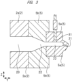
- FIG. 3 is a cross-sectional view showing a principal part of the extruder 1 of the present embodiment.
- FIG. 3 substantially corresponds to a cross-sectional view taken along the line A1-A1 shown in FIG. 2 .
- FIG. 4 is a cross-sectional view showing a principal part of a modification of the extruder 1 of the present embodiment, and it shows a cross section corresponding to FIG. 3 . Note that illustration of fixing members (screws, etc.) for fixing each member is omitted in FIG. 2 to FIG. 4 for the sake of simplification.
- FIG. 3 is a cross-sectional view showing a principal part of the extruder 1 of the present embodiment.
- FIG. 3 substantially corresponds to a cross-sectional view taken along the line A1-A1 shown in FIG. 2 .
- FIG. 4 is
- FIG. 5 is a plan view showing a flange portion 2a of the cylinder 2, an opening 23, a resin flow path portion 22, and the plurality of holes 21 formed in the die 5.
- the flow of molten resin is schematically shown by arrows.
- FIG. 3 and FIG. 4 correspond to the cross-sectional views taken along the line A1-A1 in FIG. 2 , and also correspond to the cross-sectional views taken along the line A2-A2 in FIG. 5 .
- FIG. 6 is a perspective view showing the breaker plate 32.
- FIG. 2 to FIG. 5 show the X direction, the Y direction, and the Z direction.
- the X direction, the Y direction, and the Z direction are directions intersecting each other, and more particularly are directions orthogonal to each other. Therefore, the X direction and the Y direction are orthogonal to each other, and the Z direction is orthogonal to the X direction and the Y direction.
- the X direction and Y direction correspond to the horizontal direction, and the Z direction corresponds to the vertical direction (height direction).
- the Y direction is the extending direction (longitudinal direction, axial direction) of the cylinder 2 and is also the direction in which the molten resin mainly flows through the opening 23 and the resin flow path portion 22.
- the die 5 has the plurality of holes (die hole, discharge port, nozzle, opening) 21 for discharging the molten resin (here, strand 15 made of molten resin) and the resin flow path portion 22 that guides the molten resin supplied (introduced) from the cylinder 2 to the plurality of holes 21.
- the resin flow path portion 22 and the plurality of holes 21 are formed in the die 5.
- the plurality of holes 21 are spatially connected to the resin flow path portion 22.
- the resin flow path portion 22 extends in the flow path direction (here, the Y direction) from the inlet through which the molten resin flows from the cylinder 2 to the plurality of holes 21.
- the plurality of holes 21 are arranged in the X direction and separated from each other.
- FIG. 2 shows a case where the plurality of holes 21 are arrayed in a zigzag arrangement, but the plurality of holes 21 may be arrayed in a single row as another aspect. Further, since FIG. 2 and FIG. 5 are schematic diagrams, the number of holes 21 in FIG. 2 does not match the number of holes 21 in FIG. 5 , but they actually match.
- the number of holes 21 formed in the die 5 can be, for example, about 3 to 100.
- each hole 21 preferably extends obliquely downward.
- the molten resin is discharged obliquely downward from the plurality of holes 21, which makes it easier to guide the strand 15 to the cooling bath 13.
- the plurality of holes 21 communicate with (are spatially connected to) the common resin flow path portion 22.
- the resin flow path portion 22 and the plurality of holes 21 are spaces in which the molten resin supplied (introduced) to the die 5 can flow (move).
- the resin flow path portion 22 and the plurality of holes 21 can be regarded also as a flow path (resin flow path) formed in the die 5 through which the molten resin passes.
- the resin flow path composed of the resin flow path portion 22 and the plurality of holes 21 is surrounded by the metal material constituting the die 5.
- the plurality of holes 21 function to shape the molten resin (strand 15) extruded from the die 5 into a predetermined cross-sectional shape. Namely, since the molten resin is discharged to the outside of the die 5 through the plurality of holes 21, the molten resin is shaped into the predetermined cross-sectional shape by the holes 21 and discharged (extruded) from the holes 21 to the outside of the die 5.
- the cross-sectional shape of the hole 21 cross-sectional shape substantially perpendicular to the extending direction of the hole 21
- the cross-sectional shape of the molten resin (strand 15) (cross-sectional shape substantially perpendicular to the extending direction of the strand 15) discharged from the hole 21 is also circular.
- the resin flow path portion 22 functions as a flow path (resin flow path) for guiding the molten resin supplied from the cylinder 2 to the die 5 to the plurality of holes 21.
- the die 5 is composed of a die member (die main body portion) 5a and a die member (die holder portion, die holding portion) 5b. Namely, the die 5 has the die member 5a and the die member 5b, and the die member 5b is attached to the flange portion 2a at the tip (downstream tip) of the cylinder 2 of the extruder 1 and the die member 5a is attached to the front side of the die member 5a (the side opposite to the side connected to the flange portion 2a of the cylinder 2) . Therefore, the die member 5a is held by the flange portion 2a of the cylinder 2 via the die member 5b, and the die member 5b has a function of holding the die member 5a.
- the plurality of holes 21 are formed in the die member 5a.
- the resin flow path portion 22 is formed over the die member 5a and the die member 5b, and is mainly formed in the die member 5b. Therefore, the die member 5b has a function of holding the die member 5a in which the plurality of holes 21 are formed and defining (specifying) the resin flow path portion 22 for guiding the molten resin from the cylinder 2 to the plurality of holes 21.
- the die 5 can be composed of a single integral member, the plurality of holes 21 and the resin flow path portion 22 can be easily formed and the processing of the die 5 becomes easy if the die 5 is composed of a plurality of members (here, die members 5a and 5b). Since it is the hole 21 formed in the die member 5a that defines the cross-sectional shape of the strand 15, it is also possible to regard the die member 5a as a die and the die member 5b as a die holder portion for holding the die (die member 5a).
- the die member 5b can be composed of a plurality of members (metal members, mold members), and in such a case, the die member 5b can be configured by fixing the plurality of members with fixing members such as screws or bolts.
- the die 5 is preferably made of a metal material, and thus the die members 5a and 5b are preferably made of a metal material.
- the die member 5a is fixed to the die member 5b by fixing members (not shown) such as screws or bolts. Further, the die member 5b is attached and fixed to the flange portion 2a of the cylinder 2 by fixing members (not shown) such as screws or bolts.
- the extruder 1 of the present embodiment includes the pressure measurement unit 31 for measuring the pressure of the molten resin in the cylinder 2 or the die 5.
- the pressure measurement unit 31 includes, for example, a pressure sensor (pressure gauge).
- the pressure measurement unit 31 can be arranged in the cylinder 2 or the die 5.
- the pressure measurement unit 31 measures the pressure of the molten resin at a position on the upstream side of the hole 21 and as close to the hole 21 as possible in the flow path of the molten resin in the extruder 1. Therefore, it is preferable that the pressure measurement unit 31 is arranged in the die 5 instead of the cylinder 2 and measures the pressure of the molten resin in the resin flow path portion 22 in the die 5 (molten resin flowing through the resin flow path portion 22). Further, it is more preferable that the pressure measurement unit 31 is arranged in the die member 5a and the pressure of the molten resin in the resin flow path portion 22 of the die member 5a (molten resin flowing through the resin flow path portion 22) is measured by the pressure measurement unit 31, and this case is shown in FIG. 3 and FIG. 4 .
- FIG. 4 is a modification of the structure of FIG. 3 , and it shows a case where the breaker plate 32 and a screen mesh 33 are used.
- the breaker plate 32 can be interposed in the middle of the flow (flow path) of the molten resin on the upstream side of the plurality of holes 21.
- the breaker plate 32 is a member in which a plurality of openings (holes) 32a through which molten resin can pass are formed (arrayed).
- the screen mesh 33 can be further interposed in the middle of the flow (flow path) of the molten resin on the upstream side of the plurality of holes 21.
- the screen mesh 33 is a net-like member and has a plurality of openings (holes) through which the molten resin can pass.
- the breaker plate 32 and the screen mesh 33 are arranged on the upstream side of the holes 21, more specifically, between the flange portion 2a of the cylinder 2 and the die 5 (therefore, between the opening 23 of the flange portion 2a and the resin flow path portion 22 of the die 5).
- the number of screen meshes 33 may be one or plural. Although it is preferable to use both the breaker plate 32 and the screen mesh 33, either one may be used.
- the opening of the screen mesh 33 is not shown in FIG. 4 .
- the screen mesh 33 and the breaker plate 32 both have a plurality of openings through which the molten resin can pass, the molten resin supplied from the cylinder 2 can flow into the resin flow path portion 22 of the die 5 through (the plurality of openings of) the screen mesh 33 and (the plurality of openings 32a of) the breaker plate 32.
- the screen mesh 33 and the breaker plate 32 have the function of filtering foreign substances in the molten resin and the function of increasing the back pressure in the cylinder 2 to increase the kneading effect of the resin in the cylinder 2.
- the die member 5b is attached to the flange portion 2a of the cylinder 2 such that the opening (outlet of the molten resin) 23 of the flange 2a at the tip of the cylinder 2 and the resin flow path portion 22 of the die 5 communicate (are spatially connected). Therefore, the molten resin conveyed while being kneaded by the screws 17 in the cylinder 2 is extruded from the opening 23 of the flange portion 2a at the tip of the cylinder 2, supplied to the resin flow path portion 22 of the die 5, flows into the plurality of holes 21 through the resin flow path portion 22, and is discharged from the plurality of holes 21 to the outside of the die 5. The molten resin discharged from the plurality of holes 21 becomes the strand 15 mentioned above.
- the molten resin extruded from the opening 23 of the flange portion 2a at the tip of the cylinder 2 is supplied to the resin flow path portion 22 of the die 5 through (the plurality of openings of) the screen mesh 33 and (the plurality of openings 32a of) the breaker plate 32.
- the extruder 1 of the present embodiment includes the pressure measurement unit 31 that measures the pressure of the molten resin in the cylinder 2 or the die 5 and the calculation unit 10 that calculates the viscosity of the molten resin based on the measured value of the pressure measurement unit 31 (pressure value of the molten resin measured by the pressure measurement unit 31).
- the process of manufacturing the resin product (here, pellets 16) by using the extruder 1 of the present embodiment includes the step of measuring the pressure of the molten resin in the cylinder 2 or the die 5 of the extruder 1 by the pressure measurement unit 31 and the step of calculating the viscosity of the molten resin by the calculation unit 10 based on the pressure of the molten resin measured by the pressure measurement unit 31.
- the molten resin extruded from the cylinder 2 is supplied to the resin flow path portion 22 of the die 5, flows into the plurality of holes 21 through the resin flow path portion 22, and is discharged (extruded) from the plurality of holes 21 to the outside of the die 5.
- pressure loss occurs when passing through the hole 21.
- the pressure loss when the molten resin passes through the hole 21 depends on the viscosity of the molten resin, and the pressure loss increases as the viscosity becomes higher and the pressure loss decreases as the viscosity becomes lower.
- the calculation unit 10 can perform such calculation of the viscosity of the molten resin based on the measured value of the pressure measurement unit 31. Specific examples of the calculation method will be described in more detail later.
- the pressure of the molten resin in the cylinder 2 or the die 5 is measured by the pressure measurement unit 31 while discharging the strand 15 made of the molten resin from the plurality of holes 21 of the die 5 by operating the extruder 1 and the viscosity of the molten resin can be calculated by the calculation unit 10 based on the measured value, the viscosity of the molten resin during the operation of the extruder 1 can be grasped in real time. Further, by continuously monitoring the pressure of the molten resin by the pressure measurement unit 31, the viscosity of the molten resin during the operation of the extruder 1 can be continuously monitored.
- the viscosity of the molten resin calculated by the calculation unit 10 can be displayed on the display unit 7, and can be displayed on the display unit 7 at all times by using, for example, numerical values or graphs.
- the process of manufacturing the resin product (here, pellets 16) by using the extruder 1 of the present embodiment further includes a step of displaying the viscosity of the molten resin calculated by the calculation unit 10 on the display unit 7. Therefore, the real-time viscosity of the molten resin during the operation of the extruder 1, the change in the viscosity over time, and the like can be easily and accurately grasped by looking at the display unit 7.
- the quality of the resin product (here, pellets 16 ) manufactured by using the extruder 1 depends on the viscosity of the molten resin formed in the cylinder 2 and discharged from the plurality of holes 21 of the die 5. For this reason, in order to appropriately manage the quality of the resin product (here, pellets 16) manufactured by using the extruder 1, it is extremely useful that the real-time viscosity of the molten resin during the operation of the extruder 1 and the change of the viscosity of the molten resin over time when the extruder 1 is operated continuously for a long period of time can be grasped.
- the continuous change of the viscosity of the molten resin over time during the operation of the extruder 1 can be visually confirmed on the display unit 7, the kneading state (kneading index) of the resin in the extruder 1 and the stability of the quality of the molten resin (strand 15) discharged from the plurality of holes 21 of the die 5 can be easily grasped.
- the cross-sectional size of the hole 21 of the die 5 (area of cross section substantially perpendicular to the direction in which the molten resin flows) is quite small as compared with the cross-sectional size of the resin flow path portion 22 of the die 5 (area of cross section substantially perpendicular to the direction in which the molten resin flows), the pressure loss of the molten resin when flowing through the resin flow path portion 22 is not so large, whereas the pressure loss of the molten resin when passing through the hole 21 is quite large.
- Equation 2 the shear stress ⁇ when the molten resin passes through the hole 21 is expressed by the following Equation 2.
- P 1 is the pressure of the molten resin immediately before passing through the hole 21, and the pressure of the molten resin measured by the pressure measurement unit 31 can be used as this pressure P 1 .
- P 0 is the pressure of the molten resin immediately after being discharged through the hole 21 to the outside of the die 5, and the atmospheric pressure can be used as the value of this pressure P 0 .
- L in Equation 2 is the length of the hole 21 (the length in the direction in which the resin flows).
- the viscosity ⁇ a of the molten resin can be calculated from Equation 3.
- the diameter D and the length L of the hole 21 and the number N of the holes 21 may be input in advance to a viscosity calculation program of the calculation unit 10, and the flow rate Q may be automatically input when the extrusion flow rate (Q 0 ) of the extruder 1 is set. Then, the pressure measurement unit 31 measures the pressure of the molten resin, and the calculation unit 10 can calculate the viscosity ⁇ a of the molten resin from Equation 3 based on the measured value.
- the pressure loss occurs in the hole 21, and the viscosity of the molten resin is calculated based on it. Therefore, it is preferable that the pressure of the molten resin at the entrance of the hole 21 and the pressure of the molten resin measured by the pressure measurement unit 31 match as much as possible, whereby the accuracy of the viscosity of the molten resin calculated based on the measured value of the pressure measurement unit 31 can be improved.
- the pressure loss due to the movement of the molten resin from the pressure measurement position by the pressure measurement unit 31 to the entrance of the hole 21 is sufficiently lower than the pressure loss due to the passage of the molten resin through the hole 21, and in order to achieve this, the pressure measurement position of the molten resin by the pressure measurement unit 31 is preferably as close to the entrance of the hole 21 as possible.
- the pressure measurement unit 31 measures the pressure of the molten resin before the hole 21 (on the upstream side of the hole 21) instead of the pressure of the molten resin in the hole 21.
- the pressure measurement unit 31 is arranged in the die 5 instead of the cylinder 2 and the pressure of the molten resin in the resin flow path portion 22 in the die 5 is measured by the pressure measurement unit 31, and it is more preferable that the pressure measurement unit 31 is arranged in the die member 5a and the pressure of the molten resin in the resin flow path portion 22 in the die member 5a is measured by the pressure measurement unit 31.
- FIG. 7 is a graph showing the correlation between the shear rate and viscosity of a resin. Values obtained when the viscosity of the molten resin is calculated from the measured values of the pressure measurement unit 31 according to the method of the first example described above are plotted with rhombuses. A viscosity fitting curve obtained by measuring the viscosity of the manufactured resin pellets by using a capillary rheometer is shown by a solid line.
- the plot of rhombuses and the viscosity fitting curve shown by a solid line almost match each other. From this, it can be understood that, if the viscosity of the molten resin is calculated from the measured value of the pressure measurement unit 31 according to the method of the first example described above, the viscosity characteristics of the manufactured resin product (here, resin pellets) can be grasped and the quality of the manufactured resin product (resin pellets) can be managed.
- the viscosity of the molten resin can be calculated by using the method of the first example described above based on the measured value of the pressure measurement unit 31 without taking into account the pressure loss when passing through the screen mesh 33 and the breaker plate 32.
- the viscosity of the molten resin is measured by the pressure measurement unit 31 on the downstream side of the screen mesh 33 and the breaker plate 32, even when the screen mesh 33 and the breaker plate 32 are clogged due to some factor, it is possible to prevent the measured value of the pressure measurement unit 31 from being affected by the clogging, so that the stability of the measured value of the pressure measurement unit 31 can be improved. Therefore, also in the case of the structure of FIG. 4 , it is preferable that the viscosity of the molten resin is measured by the pressure measurement unit 31 on the downstream side of the screen mesh 33 and the breaker plate 32, and thus the pressure measurement unit 31 is preferably arranged in the die 5, and is more preferably arranged in the die member 5a.
- the viscosity of the molten resin can be calculated based on the measured value of the pressure measurement unit 31 by using the method of the second example described below.
- FIG. 8 is an explanatory diagram showing a structure of a tip portion of the extruder 1 and a graph showing the pressure of molten resin at each position of the structure. Although illustration of the pressure measurement unit 31 is omitted in FIG. 8 , the structure in FIG. 8 is the same as that of FIG. 4 other than that.
- the pressure of the molten resin greatly decreases and the pressure loss occurs when passing through the opening of the screen mesh 33 and the opening 32a of the breaker plate 32 and when passing through the hole 21.
- the pressure loss when passing through the resin flow path portion 22 is considerably small. Therefore, if the pressure measured value when the viscosity of the molten resin is measured by the pressure measurement unit 31 on the upstream side of the screen mesh 33 and the breaker plate 32 (that is, the pressure measurement unit 31 is arranged in the cylinder 2) is defined as Pa, the pressure measured value Pa is approximated and expressed by the following Equation 4.
- ⁇ P1 in Equation 4 is the pressure loss when the molten resin passes through the hole 21
- ⁇ P2 is the pressure loss when the molten resin passes through the opening of the screen mesh 33 and the opening 32a of the breaker plate 32.
- the viscosity ⁇ a of the molten resin is constant.
- Equation 5 By transforming the Equation 1 above, the following Equation 5 is obtained.
- D 1 in Equation 5 is the diameter of the hole 21, and Q 1 in Equation 5 is the flow rate of the molten resin passing through each hole 21.
- Q 0 is the flow rate of the molten resin supplied from the cylinder 2 to the resin flow path portion 22 of the die 5
- N 1 is the number of holes 21.
- Q 0 can be set as an extrusion flow rate set value when operating the extruder 1.
- L 1 in Equation 5 is the length of the hole 21 (the length in the direction in which the resin flows).
- Equation 6 ⁇ P2 in Equation 5 is expressed by the following Equation 6.
- ⁇ P 2 ⁇ P 2 B + ⁇ P 2 M
- ⁇ P2 B in Equation 6 is the pressure loss when passing through the opening 32a of the breaker plate 32
- ⁇ P2 M in Equation 6 is the pressure loss when passing through (the opening of) the screen mesh 33.
- ⁇ P2 is expressed by the sum (total) of ⁇ P2 B and ⁇ P2 M .
- the pressure loss AP2 B when passing through the opening 32a of the breaker plate 32 can be calculated in the same manner as the pressure loss ⁇ P1 when passing through the hole 21, and is expressed by the following Equation 7.
- D 2 in Equation 7 is the diameter of the opening 32a of the breaker plate 32
- Q 2 in Equation 7 is the flow rate of the molten resin passing through each opening 32a.
- Q 0 is the flow rate of the molten resin supplied from the cylinder 2 to the resin flow path portion 22 of the die 5
- N 2 is the number of openings 32a.
- Q 0 can be set as an extrusion flow rate set value when operating the extruder 1.
- L 2 in Equation 7 is the length of the opening 32a of the breaker plate 32 (the length in the direction in which the resin flows).
- the pressure loss ⁇ P2 M when passing through the screen mesh 33 can be calculated by the following Equation 8.
- ⁇ P 2 M ⁇ ⁇ u ⁇ ⁇ a + ⁇ ⁇ ⁇ ⁇ u 2 Pa
- Equation 8 is the flow velocity of the molten resin
- ⁇ is the viscous resistance coefficient
- ⁇ is the inertial resistance coefficient
- ⁇ is the density.
- the viscous resistance coefficient ⁇ and the inertial resistance coefficient ⁇ are the values specific to the screen mesh and can be provided by the manufacturer of the screen mesh. Also, when a plurality of screen meshes 33 are used in combination, the ⁇ P2 M obtained by Equation 8 may be added up for the number of screen meshes to be used.
- Equation 9 is obtained.
- Equation 9 relates to the pressure loss when passing through the breaker plate 32
- the part C in Equation 9 relates to the pressure loss when passing through the hole 21
- the parts B and E in Equation 9 relate to the pressure loss when passing through the screen mesh 33.
- the viscosity ⁇ a contributes to the parts A, B, and C. Therefore, by transforming Equation 9, the following Equation 10 is obtained.
- A, B, C, and E in Equation 10 are the parts indicated by A, B, C, and E in Equation 9, respectively.
- Equation 11 By transforming Equation 10, the following Equation 11 is obtained.
- the viscosity of the molten resin is measured by the pressure measurement unit 31 on the upstream side of the screen mesh 33 and the breaker plate 32 from this equation 11, and the viscosity ⁇ a of the molten resin can be calculated based on the pressure measured value Pa.
- the calculation unit 10 can calculate the viscosity of the molten resin based on the pressure measured value of the pressure measurement unit 31.
- the pressure measurement unit 31 is arranged in the cylinder 2 and the viscosity of the molten resin is measured by the pressure measurement unit 31 on the upstream side of the screen mesh 33 and the breaker plate 32, if the screen mesh 33 and the breaker plate 32 are clogged due to some factor, the measured value of the pressure measurement unit 31 is affected by the clogging. This is not desirable because it leads to a deviation (error) between the calculated viscosity and the actual viscosity when the calculation unit 10 calculates the viscosity of the molten resin based on the measured value of the pressure measurement unit 31.
- the pressure of the molten resin is measured by using the pressure measurement unit 31 on the downstream side of the members and on the upstream side of the plurality of holes 21.
- the method of the first example described above may be used to calculate the viscosity. In this way, even when members having a plurality of openings through which the molten resin passes such as the screen mesh 33 and the breaker plate 32 are clogged due to some factor, it is possible to prevent the measured value of the pressure measurement unit 31 from being affected by the clogging.
- the calculation unit 10 calculates the viscosity of the molten resin based on the measured value of the pressure measurement unit 31, the occurrence of deviation (error) between the calculated viscosity and the actual viscosity can be more accurately suppressed or prevented.
- FIG. 9 is a plan view of the die 5 used in the modification of the extruder 1 of the present embodiment, and corresponds to FIG. 2 above.
- the number of holes (openings for discharging molten resin) 21 provided in the die 5 is plural (two or more), but the number of holes (openings for discharging molten resin) 21 is one in the case of FIG. 9 .
- the cross-sectional shape of the hole 21 is, for example, a slit shape, and the molten resin discharged from the slit-shaped hole 21 in this case is formed into a film shape instead of a strand shape.
- the manufactured resin product is, for example, a resin film.
- the resin film is conveyed to and wound up by a winding machine (not shown). Also in such a case, as described above, it is possible to measure the pressure of the molten resin in the cylinder 2 or the die 5 of the extruder 1 by the pressure measurement unit 31, calculate the viscosity of the molten resin by the calculation unit 10 based on the measured value of the pressure measurement unit 31, and display the viscosity of the molten resin on the display unit 7. In this way, the effects as described above can be obtained.
Landscapes
- Engineering & Computer Science (AREA)
- Mechanical Engineering (AREA)
- Manufacturing & Machinery (AREA)
- Physics & Mathematics (AREA)
- Health & Medical Sciences (AREA)
- Life Sciences & Earth Sciences (AREA)
- Chemical & Material Sciences (AREA)
- Analytical Chemistry (AREA)
- Biochemistry (AREA)
- General Health & Medical Sciences (AREA)
- General Physics & Mathematics (AREA)
- Immunology (AREA)
- Pathology (AREA)
- Extrusion Moulding Of Plastics Or The Like (AREA)
- Measuring Fluid Pressure (AREA)
- Processing And Handling Of Plastics And Other Materials For Molding In General (AREA)
Abstract
Description
- The present invention relates to an extruder and a method of manufacturing a resin product.
-
Japanese Unexamined Patent Application Publication No. 2016-7819 - Patent Document 1:
Japanese Unexamined Patent Application Publication No. 2016-7819 - It is possible to manufacture a resin product, for example, resin pellets, by using the resin extruded from an extruder. In order to manage the quality of the manufactured resin pellets, it is necessary to check whether the quality is stable by periodically extracting the manufactured resin pellets and measuring the viscosity thereof. However, it is troublesome to periodically extract the manufactured resin pellets to measure the viscosity thereof, which makes the quality management of the resin pellets difficult and increases the manufacturing cost of the resin pellets. For this reason, it is desired to make it easier to manage the quality of the resin product manufactured by using the resin extruded from the extruder.
- Other problems and novel features will be apparent from the descriptions of this specification and accompanying drawings.
- According to one embodiment, an extruder includes a cylinder, a die having a hole to discharge a molten resin, a pressure measurement unit configured to measure a pressure of the molten resin in the cylinder or the die, and a calculation unit configured to calculate a viscosity of the molten resin based on a measured value of the pressure measurement unit.
- According to one embodiment, a method of manufacturing a resin product includes a step of (a) preparing an extruder including a cylinder and a die attached to the cylinder and a step of (b) supplying a resin material into the cylinder to form a molten resin and discharging the molten resin from a hole of the die. The method of manufacturing a resin product further includes a step of (c) measuring a pressure of the molten resin in the cylinder or the die and a step of (d) calculating a viscosity of the molten resin based on the pressure of the molten resin measured in the step (c).
- According to one embodiment, it becomes easy to manage the quality of the resin product manufactured by using the resin extruded from the extruder.
-
-
FIG. 1 is an explanatory diagram showing a configuration example of a pellet manufacturing system using an extruder according to one embodiment; -
FIG. 2 is a front view of the extruder according to one embodiment; -
FIG. 3 is a cross-sectional view showing a principal part of the extruder according to one embodiment; -
FIG. 4 is a cross-sectional view showing a principal part of a modification of the extruder according to one embodiment; -
FIG. 5 is a plan view showing a flange portion of a cylinder, a resin flow path portion and a plurality of holes formed in a die; -
FIG. 6 is a perspective view showing a breaker plate; -
FIG. 7 is a graph showing a correlation between the shear rate and viscosity of a resin; -
FIG. 8 is an explanatory diagram showing a structure of a tip portion of the extruder and a graph showing the pressure of a molten resin at each position of the structure; and -
FIG. 9 is a plan view of a die used in another modification of the extruder according to one embodiment. - Hereinafter, an embodiment will be described in detail with reference to drawings. Note that the members having the same function are denoted by the same reference characters throughout the drawings for describing the embodiment, and the repetitive description thereof will be omitted. Further, in the following embodiment, the description of the same or similar part will not be repeated in principle unless particularly required.
-
FIG. 1 is an explanatory diagram (side view) showing a configuration example of a pellet manufacturing system (pellet manufacturing apparatus) 12 using an extruder (extrusion molding machine) 1 according to the present embodiment. - First, a schematic configuration of the
extruder 1 will be described with reference toFIG. 1 . Theextruder 1 shown inFIG. 1 includes a cylinder (barrel) 2, twoscrews 17 rotatably (freely rotatably) arranged in thecylinder 2, arotary drive mechanism 3 for rotating thescrews 17 in thecylinder 2, a hopper (resin input unit) 4 arranged on the upstream side (rear end side) of thecylinder 2, a die (mold) 5 attached to the downstream end of thecylinder 2, and an operation panel (operation unit, operation console) 6. Thehopper 4 is connected to an upper surface of thecylinder 2, and a resin can be supplied into thecylinder 2 through thehopper 4. The temperature of thecylinder 2 is controlled by a temperature adjusting unit (temperature adjusting mechanism) (not shown) such as a heater. Theextruder 1 may further include a filler feeder (not shown) connected to thecylinder 2, and in such a case, desired filler can be fed into thecylinder 2 from the filler feeder. - When referring to the "downstream side" and "upstream side" with respect to the
extruder 1, the "downstream side" means the downstream side of the resin flow in theextruder 1, and the "upstream side" means the upstream side of the resin flow in theextruder 1. Therefore, in theextruder 1, the side closer to a plurality ofholes 21 of the die 5 described later is the downstream side, and the side farther from the plurality ofholes 21 of thedie 5, that is, the side closer to thehopper 4 is the upstream side. - The two
screws 17 are rotatably (freely rotatably) inserted and incorporated inside thecylinder 2. Therefore, theextruder 1 can be regarded also as a twin-screw extruder (twin-screw extrusion machine). The twoscrews 17 are arranged so as to mesh with each other and rotated in thecylinder 2. The longitudinal direction (long side direction, axial direction, extending direction) of thecylinder 2 and the longitudinal direction (long side direction, axial direction, extending direction) of the screws in thecylinder 2 are the same. - In the present embodiment, the case where the number of
screws 17 in thecylinder 2 is two is described, but the number ofscrews 17 in thecylinder 2 may be one as another aspect. However, since the spatial volume can be increased when the number ofscrews 17 in thecylinder 2 is two, the supply capacity of the raw material can be increased in the case of double screws (two screws 17) as compared with the case of single screw (one screw 17) if the diameter of the screw is the same. - The die 5 can function to discharge a molten resin extruded from the
cylinder 2 of theextruder 1 while shaping it into a predetermined cross-sectional shape (here, string-like shape). Therefore, the die 5 is a die (mold) for extrusion molding. - In this application, "melting" is not limited to melting with heat, but includes melting with a solvent or the like. For this reason, the case of melting a resin with a solvent, the case of melting a resin with microwaves, and the like may also be included in the "molten resin" in addition to the case of melting a resin by heating. Further, liquid resin may also be included in the "molten resin".
- The
operation panel 6 includes adisplay unit 7 and aninput unit 8. Theinput unit 8 includes, for example, a keyboard, switches, dials, buttons, a touch panel, and the like for use in input. The operation of theextruder 1 can be controlled by inputting commands, data, and the like necessary for operating theextruder 1 into theinput unit 8. Thedisplay unit 7 can display, for example, information input to theinput unit 8, information related to the operation and state of theextruder 1, and the like. - The
operation panel 6 includes acontrol unit 9 that controls the operation of theextruder 1. Thecontrol unit 9 controls the operation of theextruder 1 in accordance with commands, data, and the like input to theinput unit 8. Thecontrol unit 9 can be configured by a computer including, for example, a semiconductor chip for control (semiconductor processor) and a semiconductor chip for storage (memory chip). - Also, the
control unit 9 includes acalculation unit 10 that calculates the viscosity of the molten resin based on the measured value of apressure measurement unit 31 described later (the pressure value of the molten resin measured by the pressure measurement unit 31). Thecalculation unit 10 is configured by, for example, a semiconductor chip for calculation (semiconductor processor). The viscosity calculated by thecalculation unit 10 can be displayed on thedisplay unit 7. - Also, the
control unit 9 includes astorage unit 11. The viscosity calculated by thecalculation unit 10 can also be stored (recorded) in thestorage unit 11. Thestorage unit 11 is configured by, for example, a semiconductor chip for storage (memory chip). - Here, the case where the
control unit 9 is built in theoperation panel 6 is described, but the control unit 9 (computer for control) may be provided separately from the operation panel 6 (that is, outside the operation panel 6) as another aspect. Further, here, the case where thecalculation unit 10 and thestorage unit 11 are included in thecontrol unit 9 is described, but one or both of thecalculation unit 10 and thestorage unit 11 may be provided separately from the control unit 9 (computer for control). Also, thedisplay unit 7 may be provided separately from the operation panel 6 (that is, outside the operation panel 6). - The
pellet manufacturing system 12 shown inFIG. 1 further includes a coolingbath 13 and a cuttingmachine 14 in addition to theextruder 1. - Next, the operation of the
pellet manufacturing system 12 including theextruder 1 shown inFIG. 1 will be briefly described. - In the
extruder 1, the resin material (thermoplastic resin) supplied from thehopper 4 into thecylinder 2 is melted while being sent forward by the rotation of thescrews 17 in the cylinder 2 (that is, becomes molten resin). In the case where the filler is supplied into thecylinder 2 from the filler feeder (not shown), the resin (molten resin) and the filler are kneaded by the rotation of thescrews 17 in thecylinder 2 of theextruder 1, and thus the filler is contained in the molten resin in thecylinder 2. Note that the operation of theextruder 1 is performed by inputting commands, data, and the like required for operating theextruder 1 to theinput unit 8, and the operation of theextruder 1 is controlled by thecontrol unit 9. - In the
extruder 1, the molten resin sent forward in thecylinder 2 by the rotation of thescrews 17 is extruded (discharged) from the die 5 (more specifically, the plurality ofholes 21 of thedie 5 described later) attached to the tip of thecylinder 2. At this time, the molten resin is shaped into a string-like shape by thedie 5 and extruded as a strand (resin strand) 15 from thedie 5. Thestrand 15 extruded from thedie 5 of theextruder 1 is cooled and solidified (cured) in the coolingbath 13. The solidifiedstrand 15 is cut into a predetermined length by the cuttingmachine 14. As a result, pellets (resin pellets) 16 are manufactured as a resin product. In thepellet manufacturing system 12, theextruder 1 can function as a strand manufacturing apparatus. - Therefore, the process of manufacturing the resin product (here, pellets 16) includes a step of preparing the
extruder 1 having thecylinder 2 and thedie 5 attached to thecylinder 2 and a step of supplying a resin material into thecylinder 2 of theextruder 1 to form the molten resin and discharging the molten resin from theholes 21 of thedie 5. The process of manufacturing the resin product (here, pellets 16) further includes a step of measuring the pressure of the molten resin in thecylinder 2 or thedie 5 of theextruder 1 by thepressure measurement unit 31 described later and a step of calculating the viscosity of the molten resin by thecalculation unit 10 based on the pressure of the molten resin measured by thepressure measurement unit 31. The measurement of the pressure of the molten resin by thepressure measurement unit 31 and the calculation of the viscosity of the molten resin by thecalculation unit 10 will be described later in detail. - Next, the configuration around the tip of the
extruder 1 of the present embodiment, in particular, the configuration of the die (mold) 5 will be described with reference toFIG. 2 to FIG 6 . -
FIG. 2 is a front view of theextruder 1 of the present embodiment, and it shows a front view of thedie 5 attached to the tip of thecylinder 2.FIG. 3 is a cross-sectional view showing a principal part of theextruder 1 of the present embodiment.FIG. 3 substantially corresponds to a cross-sectional view taken along the line A1-A1 shown inFIG. 2 .FIG. 4 is a cross-sectional view showing a principal part of a modification of theextruder 1 of the present embodiment, and it shows a cross section corresponding toFIG. 3 . Note that illustration of fixing members (screws, etc.) for fixing each member is omitted inFIG. 2 to FIG. 4 for the sake of simplification.FIG. 5 is a plan view showing aflange portion 2a of thecylinder 2, anopening 23, a resinflow path portion 22, and the plurality ofholes 21 formed in thedie 5. InFIG. 5 , the flow of molten resin is schematically shown by arrows. Moreover, when abreaker plate 32 is provided as shown inFIG. 4 , thebreaker plate 32 is located at the position indicated by the dotted line inFIG. 5 . Note thatFIG. 3 andFIG. 4 correspond to the cross-sectional views taken along the line A1-A1 inFIG. 2 , and also correspond to the cross-sectional views taken along the line A2-A2 inFIG. 5 .FIG. 6 is a perspective view showing thebreaker plate 32. - Note that
FIG. 2 to FIG. 5 show the X direction, the Y direction, and the Z direction. The X direction, the Y direction, and the Z direction are directions intersecting each other, and more particularly are directions orthogonal to each other. Therefore, the X direction and the Y direction are orthogonal to each other, and the Z direction is orthogonal to the X direction and the Y direction. The X direction and Y direction correspond to the horizontal direction, and the Z direction corresponds to the vertical direction (height direction). The Y direction is the extending direction (longitudinal direction, axial direction) of thecylinder 2 and is also the direction in which the molten resin mainly flows through theopening 23 and the resinflow path portion 22. - The
die 5 has the plurality of holes (die hole, discharge port, nozzle, opening) 21 for discharging the molten resin (here, strand 15 made of molten resin) and the resinflow path portion 22 that guides the molten resin supplied (introduced) from thecylinder 2 to the plurality ofholes 21. Namely, the resinflow path portion 22 and the plurality ofholes 21 are formed in thedie 5. The plurality ofholes 21 are spatially connected to the resinflow path portion 22. The resinflow path portion 22 extends in the flow path direction (here, the Y direction) from the inlet through which the molten resin flows from thecylinder 2 to the plurality ofholes 21. In thedie 5, the plurality ofholes 21 are arranged in the X direction and separated from each other.FIG. 2 shows a case where the plurality ofholes 21 are arrayed in a zigzag arrangement, but the plurality ofholes 21 may be arrayed in a single row as another aspect. Further, sinceFIG. 2 andFIG. 5 are schematic diagrams, the number ofholes 21 inFIG. 2 does not match the number ofholes 21 inFIG. 5 , but they actually match. The number ofholes 21 formed in thedie 5 can be, for example, about 3 to 100. - Moreover, it is preferable that the extending direction of each of the plurality of
holes 21 provided in thedie 5 is inclined downward with respect to the Y direction. Namely, eachhole 21 preferably extends obliquely downward. As a result, the molten resin is discharged obliquely downward from the plurality ofholes 21, which makes it easier to guide thestrand 15 to the coolingbath 13. - The plurality of
holes 21 communicate with (are spatially connected to) the common resinflow path portion 22. The resinflow path portion 22 and the plurality ofholes 21 are spaces in which the molten resin supplied (introduced) to thedie 5 can flow (move). The resinflow path portion 22 and the plurality ofholes 21 can be regarded also as a flow path (resin flow path) formed in thedie 5 through which the molten resin passes. The resin flow path composed of the resinflow path portion 22 and the plurality ofholes 21 is surrounded by the metal material constituting thedie 5. - The plurality of
holes 21 function to shape the molten resin (strand 15) extruded from thedie 5 into a predetermined cross-sectional shape. Namely, since the molten resin is discharged to the outside of thedie 5 through the plurality ofholes 21, the molten resin is shaped into the predetermined cross-sectional shape by theholes 21 and discharged (extruded) from theholes 21 to the outside of thedie 5. For example, when the cross-sectional shape of the hole 21 (cross-sectional shape substantially perpendicular to the extending direction of the hole 21) is circular, the cross-sectional shape of the molten resin (strand 15) (cross-sectional shape substantially perpendicular to the extending direction of the strand 15) discharged from thehole 21 is also circular. Further, it is also possible to control the diameter of thestrand 15 by the diameter of thehole 21. However, the diameter of thestrand 15 changes also depending on the flow velocity of the molten resin when it is discharged from thehole 21. The resinflow path portion 22 functions as a flow path (resin flow path) for guiding the molten resin supplied from thecylinder 2 to thedie 5 to the plurality ofholes 21. - The
die 5 is composed of a die member (die main body portion) 5a and a die member (die holder portion, die holding portion) 5b. Namely, thedie 5 has thedie member 5a and thedie member 5b, and thedie member 5b is attached to theflange portion 2a at the tip (downstream tip) of thecylinder 2 of theextruder 1 and thedie member 5a is attached to the front side of thedie member 5a (the side opposite to the side connected to theflange portion 2a of the cylinder 2) . Therefore, thedie member 5a is held by theflange portion 2a of thecylinder 2 via thedie member 5b, and thedie member 5b has a function of holding thedie member 5a. The plurality ofholes 21 are formed in thedie member 5a. The resinflow path portion 22 is formed over thedie member 5a and thedie member 5b, and is mainly formed in thedie member 5b. Therefore, thedie member 5b has a function of holding thedie member 5a in which the plurality ofholes 21 are formed and defining (specifying) the resinflow path portion 22 for guiding the molten resin from thecylinder 2 to the plurality ofholes 21. - Although the
die 5 can be composed of a single integral member, the plurality ofholes 21 and the resinflow path portion 22 can be easily formed and the processing of thedie 5 becomes easy if thedie 5 is composed of a plurality of members (here, diemembers hole 21 formed in thedie member 5a that defines the cross-sectional shape of thestrand 15, it is also possible to regard thedie member 5a as a die and thedie member 5b as a die holder portion for holding the die (diemember 5a). Alternatively, thedie member 5b can be composed of a plurality of members (metal members, mold members), and in such a case, thedie member 5b can be configured by fixing the plurality of members with fixing members such as screws or bolts. - The
die 5 is preferably made of a metal material, and thus thedie members die member 5a is fixed to thedie member 5b by fixing members (not shown) such as screws or bolts. Further, thedie member 5b is attached and fixed to theflange portion 2a of thecylinder 2 by fixing members (not shown) such as screws or bolts. - The
extruder 1 of the present embodiment includes thepressure measurement unit 31 for measuring the pressure of the molten resin in thecylinder 2 or thedie 5. Thepressure measurement unit 31 includes, for example, a pressure sensor (pressure gauge). Thepressure measurement unit 31 can be arranged in thecylinder 2 or thedie 5. - However, it is desirable that the
pressure measurement unit 31 measures the pressure of the molten resin at a position on the upstream side of thehole 21 and as close to thehole 21 as possible in the flow path of the molten resin in theextruder 1. Therefore, it is preferable that thepressure measurement unit 31 is arranged in thedie 5 instead of thecylinder 2 and measures the pressure of the molten resin in the resinflow path portion 22 in the die 5 (molten resin flowing through the resin flow path portion 22). Further, it is more preferable that thepressure measurement unit 31 is arranged in thedie member 5a and the pressure of the molten resin in the resinflow path portion 22 of thedie member 5a (molten resin flowing through the resin flow path portion 22) is measured by thepressure measurement unit 31, and this case is shown inFIG. 3 andFIG. 4 . -
FIG. 4 is a modification of the structure ofFIG. 3 , and it shows a case where thebreaker plate 32 and ascreen mesh 33 are used. As shown inFIG. 4 , thebreaker plate 32 can be interposed in the middle of the flow (flow path) of the molten resin on the upstream side of the plurality ofholes 21. As can be seen fromFIG. 4 andFIG. 6 , thebreaker plate 32 is a member in which a plurality of openings (holes) 32a through which molten resin can pass are formed (arrayed). - Further, as shown in
FIG. 4 , not only thebreaker plate 32 but also thescreen mesh 33 can be further interposed in the middle of the flow (flow path) of the molten resin on the upstream side of the plurality ofholes 21. Thescreen mesh 33 is a net-like member and has a plurality of openings (holes) through which the molten resin can pass. - The
breaker plate 32 and thescreen mesh 33 are arranged on the upstream side of theholes 21, more specifically, between theflange portion 2a of thecylinder 2 and the die 5 (therefore, between the opening 23 of theflange portion 2a and the resinflow path portion 22 of the die 5). The number of screen meshes 33 may be one or plural. Although it is preferable to use both thebreaker plate 32 and thescreen mesh 33, either one may be used. - Since the size of the opening of the
screen mesh 33 is smaller than the size of theopening 32a of thebreaker plate 32, the opening of thescreen mesh 33 is not shown inFIG. 4 . However, since thescreen mesh 33 and thebreaker plate 32 both have a plurality of openings through which the molten resin can pass, the molten resin supplied from thecylinder 2 can flow into the resinflow path portion 22 of thedie 5 through (the plurality of openings of) thescreen mesh 33 and (the plurality ofopenings 32a of) thebreaker plate 32. Thescreen mesh 33 and thebreaker plate 32 have the function of filtering foreign substances in the molten resin and the function of increasing the back pressure in thecylinder 2 to increase the kneading effect of the resin in thecylinder 2. - The
die member 5b is attached to theflange portion 2a of thecylinder 2 such that the opening (outlet of the molten resin) 23 of theflange 2a at the tip of thecylinder 2 and the resinflow path portion 22 of thedie 5 communicate (are spatially connected). Therefore, the molten resin conveyed while being kneaded by thescrews 17 in thecylinder 2 is extruded from theopening 23 of theflange portion 2a at the tip of thecylinder 2, supplied to the resinflow path portion 22 of thedie 5, flows into the plurality ofholes 21 through the resinflow path portion 22, and is discharged from the plurality ofholes 21 to the outside of thedie 5. The molten resin discharged from the plurality ofholes 21 becomes thestrand 15 mentioned above. Further, when thebreaker plate 32 and thescreen mesh 33 are provided as shown inFIG. 4 , the molten resin extruded from theopening 23 of theflange portion 2a at the tip of thecylinder 2 is supplied to the resinflow path portion 22 of thedie 5 through (the plurality of openings of) thescreen mesh 33 and (the plurality ofopenings 32a of) thebreaker plate 32. - The
extruder 1 of the present embodiment includes thepressure measurement unit 31 that measures the pressure of the molten resin in thecylinder 2 or thedie 5 and thecalculation unit 10 that calculates the viscosity of the molten resin based on the measured value of the pressure measurement unit 31 (pressure value of the molten resin measured by the pressure measurement unit 31). In addition, the process of manufacturing the resin product (here, pellets 16) by using theextruder 1 of the present embodiment includes the step of measuring the pressure of the molten resin in thecylinder 2 or thedie 5 of theextruder 1 by thepressure measurement unit 31 and the step of calculating the viscosity of the molten resin by thecalculation unit 10 based on the pressure of the molten resin measured by thepressure measurement unit 31. - The molten resin extruded from the
cylinder 2 is supplied to the resinflow path portion 22 of thedie 5, flows into the plurality ofholes 21 through the resinflow path portion 22, and is discharged (extruded) from the plurality ofholes 21 to the outside of thedie 5. At this time, since the opening diameter of thehole 21 is quite small, pressure loss occurs when passing through thehole 21. The pressure loss when the molten resin passes through thehole 21 depends on the viscosity of the molten resin, and the pressure loss increases as the viscosity becomes higher and the pressure loss decreases as the viscosity becomes lower. Therefore, if the pressure loss when the molten resin passes through thehole 21 is known, the viscosity of the molten resin passing through thehole 21 can be known (estimated). The pressure loss when the molten resin passes through thehole 21 is the difference between the pressure of the molten resin immediately before passing through thehole 21 and the pressure of the molten resin immediately after being discharged to the outside of thedie 5 through thehole 21, and the pressure of the molten resin immediately after being discharged to the outside of thedie 5 is almost equal to the atmospheric pressure. Therefore, by estimating the pressure of the molten resin immediately before passing through thehole 21 from the measured value of thepressure measurement unit 31, it is possible to estimate the pressure loss that occurs when the molten resin passes through thehole 21, and the viscosity of the molten resin passing through thehole 21 can be calculated based on the estimated pressure loss. Thecalculation unit 10 can perform such calculation of the viscosity of the molten resin based on the measured value of thepressure measurement unit 31. Specific examples of the calculation method will be described in more detail later. - Since the pressure of the molten resin in the
cylinder 2 or thedie 5 is measured by thepressure measurement unit 31 while discharging thestrand 15 made of the molten resin from the plurality ofholes 21 of thedie 5 by operating theextruder 1 and the viscosity of the molten resin can be calculated by thecalculation unit 10 based on the measured value, the viscosity of the molten resin during the operation of theextruder 1 can be grasped in real time. Further, by continuously monitoring the pressure of the molten resin by thepressure measurement unit 31, the viscosity of the molten resin during the operation of theextruder 1 can be continuously monitored. The viscosity of the molten resin calculated by thecalculation unit 10 can be displayed on thedisplay unit 7, and can be displayed on thedisplay unit 7 at all times by using, for example, numerical values or graphs. Namely, the process of manufacturing the resin product (here, pellets 16) by using theextruder 1 of the present embodiment further includes a step of displaying the viscosity of the molten resin calculated by thecalculation unit 10 on thedisplay unit 7. Therefore, the real-time viscosity of the molten resin during the operation of theextruder 1, the change in the viscosity over time, and the like can be easily and accurately grasped by looking at thedisplay unit 7. The quality of the resin product (here, pellets 16 ) manufactured by using theextruder 1 depends on the viscosity of the molten resin formed in thecylinder 2 and discharged from the plurality ofholes 21 of thedie 5. For this reason, in order to appropriately manage the quality of the resin product (here, pellets 16) manufactured by using theextruder 1, it is extremely useful that the real-time viscosity of the molten resin during the operation of theextruder 1 and the change of the viscosity of the molten resin over time when theextruder 1 is operated continuously for a long period of time can be grasped. In the present embodiment, this can be achieved because theextruder 1 includes thepressure measurement unit 31 and thecalculation unit 10, so that it becomes easy to manage the quality of the resin product (here, pellets 16) manufactured by using theextruder 1. Therefore, the manufacturing cost of the resin product (here, pellets 16) manufactured by using theextruder 1 can be suppressed. In addition, since the continuous change of the viscosity of the molten resin over time during the operation of theextruder 1 can be visually confirmed on thedisplay unit 7, the kneading state (kneading index) of the resin in theextruder 1 and the stability of the quality of the molten resin (strand 15) discharged from the plurality ofholes 21 of thedie 5 can be easily grasped. - Further, the viscosity of the molten resin calculated by the
calculation unit 10 can be stored (recorded) in thestorage unit 11. When the viscosity of the molten resin changes due to some factor, the change can be grasped in real time by thedisplay unit 7, and it is also possible to confirm afterward that the viscosity of the resin has changed due to some factor by storing (recording) the change of the molten resin over time in thestorage unit 11. - In addition, it is also possible to obtain the viscosity of the molten resin as discontinuous (periodic) data (for example, the viscosity measured at the same time every day) by the
pressure measurement unit 31 and thecalculation unit 10 and monitor the stability of the quality of the resin product (here, pellets 16) by using the data. Further, it is also possible to display the discontinuous (periodic) data and the data of the stability of the quality of the resin product (here, pellet 16) determined by the data on thedisplay unit 7. - Next, the first example of the specific method of calculating the viscosity of the molten resin based on the pressure value of the molten resin measured by the
pressure measurement unit 31 will be described. - Since the cross-sectional size of the
hole 21 of the die 5 (area of cross section substantially perpendicular to the direction in which the molten resin flows) is quite small as compared with the cross-sectional size of the resinflow path portion 22 of the die 5 (area of cross section substantially perpendicular to the direction in which the molten resin flows), the pressure loss of the molten resin when flowing through the resinflow path portion 22 is not so large, whereas the pressure loss of the molten resin when passing through thehole 21 is quite large. - The shear rate γa when the molten resin passes through the
hole 21 is expressed by the followingEquation 1. -

- D in
Equation 1 is the diameter of thehole 21, and Q inEquation 1 is the flow rate of the molten resin passing through each of theholes 21. The flow rate Q is expressed as Q=Qo/N, Qo is the flow rate of the molten resin supplied from thecylinder 2 to the resinflow path portion 22 of thedie 5, and N is the number ofholes 21. Q0 can be set as an extrusion flow rate set value when operating theextruder 1. - Also, the shear stress σ when the molten resin passes through the
hole 21 is expressed by the followingEquation 2. -

- ΔP in
Equation 2 is the pressure loss when the molten resin passes through thehole 21, and is expressed as ΔP=P1-P0. Here, P1 is the pressure of the molten resin immediately before passing through thehole 21, and the pressure of the molten resin measured by thepressure measurement unit 31 can be used as this pressure P1. P0 is the pressure of the molten resin immediately after being discharged through thehole 21 to the outside of thedie 5, and the atmospheric pressure can be used as the value of this pressure P0. L inEquation 2 is the length of the hole 21 (the length in the direction in which the resin flows). - The viscosity ηa of the molten resin is expressed by the following
Equation 3 based onEquations -

- In this
Equation 3, the diameter D of thehole 21 and the length L of thehole 21 are known values, and the flow rate Q (=Q0/N) of the molten resin passing through eachhole 21 is the value that can be controlled by the set value of the extrusion flow rate (Q0) when operating theextruder 1. Therefore, as can be seen fromEquation 3, the viscosity ηa can be calculated if the pressure loss ΔP when the molten resin passes through thehole 21 is known. As described above, by using the atmospheric pressure as the value of the pressure P0 and the pressure of the molten resin measured by thepressure measurement unit 31 as the value of the pressure P1 in ΔP=P1-P0, the viscosity ηa of the molten resin can be calculated fromEquation 3. - For example, the diameter D and the length L of the
hole 21 and the number N of theholes 21 may be input in advance to a viscosity calculation program of thecalculation unit 10, and the flow rate Q may be automatically input when the extrusion flow rate (Q0) of theextruder 1 is set. Then, thepressure measurement unit 31 measures the pressure of the molten resin, and thecalculation unit 10 can calculate the viscosity ηa of the molten resin fromEquation 3 based on the measured value. - Further, it is assumed here that the pressure loss occurs in the
hole 21, and the viscosity of the molten resin is calculated based on it. Therefore, it is preferable that the pressure of the molten resin at the entrance of thehole 21 and the pressure of the molten resin measured by thepressure measurement unit 31 match as much as possible, whereby the accuracy of the viscosity of the molten resin calculated based on the measured value of thepressure measurement unit 31 can be improved. For this reason, it is preferable that the pressure loss due to the movement of the molten resin from the pressure measurement position by thepressure measurement unit 31 to the entrance of thehole 21 is sufficiently lower than the pressure loss due to the passage of the molten resin through thehole 21, and in order to achieve this, the pressure measurement position of the molten resin by thepressure measurement unit 31 is preferably as close to the entrance of thehole 21 as possible. However, thepressure measurement unit 31 measures the pressure of the molten resin before the hole 21 (on the upstream side of the hole 21) instead of the pressure of the molten resin in thehole 21. From this point of view, it is preferable that thepressure measurement unit 31 is arranged in thedie 5 instead of thecylinder 2 and the pressure of the molten resin in the resinflow path portion 22 in thedie 5 is measured by thepressure measurement unit 31, and it is more preferable that thepressure measurement unit 31 is arranged in thedie member 5a and the pressure of the molten resin in the resinflow path portion 22 in thedie member 5a is measured by thepressure measurement unit 31. -
FIG. 7 is a graph showing the correlation between the shear rate and viscosity of a resin. Values obtained when the viscosity of the molten resin is calculated from the measured values of thepressure measurement unit 31 according to the method of the first example described above are plotted with rhombuses. A viscosity fitting curve obtained by measuring the viscosity of the manufactured resin pellets by using a capillary rheometer is shown by a solid line. - As can be seen from
FIG. 7 , the plot of rhombuses and the viscosity fitting curve shown by a solid line almost match each other. From this, it can be understood that, if the viscosity of the molten resin is calculated from the measured value of thepressure measurement unit 31 according to the method of the first example described above, the viscosity characteristics of the manufactured resin product (here, resin pellets) can be grasped and the quality of the manufactured resin product (resin pellets) can be managed. - Next, the second example of the specific method of calculating the viscosity of the molten resin based on the pressure value of the molten resin measured by the
pressure measurement unit 31 will be described. This second example assumes that thebreaker plate 32 and thescreen mesh 33 are used as in the structure ofFIG. 4 . - Also in the case of the structure shown in
FIG. 4 , the pressure loss of the molten resin when flowing through the resinflow path portion 22 is not so large, whereas the pressure loss of the molten resin when passing through thehole 21 is quite large as described above. However, in the case of the structure shown inFIG. 4 , the pressure loss of the molten resin when passing through openings of thescreen mesh 33 andopenings 32a of thebreaker plate 32 also becomes quite large. - Therefore, also in the case of the structure shown in
FIG. 4 , if the viscosity of the molten resin is measured by thepressure measurement unit 31 on the downstream side of thescreen mesh 33 and thebreaker plate 32, the viscosity of the molten resin can be calculated by using the method of the first example described above based on the measured value of thepressure measurement unit 31 without taking into account the pressure loss when passing through thescreen mesh 33 and thebreaker plate 32. If the viscosity of the molten resin is measured by thepressure measurement unit 31 on the downstream side of thescreen mesh 33 and thebreaker plate 32, even when thescreen mesh 33 and thebreaker plate 32 are clogged due to some factor, it is possible to prevent the measured value of thepressure measurement unit 31 from being affected by the clogging, so that the stability of the measured value of thepressure measurement unit 31 can be improved. Therefore, also in the case of the structure ofFIG. 4 , it is preferable that the viscosity of the molten resin is measured by thepressure measurement unit 31 on the downstream side of thescreen mesh 33 and thebreaker plate 32, and thus thepressure measurement unit 31 is preferably arranged in thedie 5, and is more preferably arranged in thedie member 5a. - However, even if the viscosity of the molten resin is measured by the
pressure measurement unit 31 on the upstream side of thescreen mesh 33 and the breaker plate 32 (that is, thepressure measurement unit 31 is arranged in the cylinder 2) in the case of the structure shown inFIG. 4 , the viscosity of the molten resin can be calculated based on the measured value of thepressure measurement unit 31 by using the method of the second example described below. -
FIG. 8 is an explanatory diagram showing a structure of a tip portion of theextruder 1 and a graph showing the pressure of molten resin at each position of the structure. Although illustration of thepressure measurement unit 31 is omitted inFIG. 8 , the structure inFIG. 8 is the same as that ofFIG. 4 other than that. - As can be seen from
FIG. 8 , the pressure of the molten resin greatly decreases and the pressure loss occurs when passing through the opening of thescreen mesh 33 and theopening 32a of thebreaker plate 32 and when passing through thehole 21. As compared with that, the pressure loss when passing through the resinflow path portion 22 is considerably small. Therefore, if the pressure measured value when the viscosity of the molten resin is measured by thepressure measurement unit 31 on the upstream side of thescreen mesh 33 and the breaker plate 32 (that is, thepressure measurement unit 31 is arranged in the cylinder 2) is defined as Pa, the pressure measured value Pa is approximated and expressed by the followingEquation 4. -

- Here, ΔP1 in
Equation 4 is the pressure loss when the molten resin passes through thehole 21, and ΔP2 is the pressure loss when the molten resin passes through the opening of thescreen mesh 33 and theopening 32a of thebreaker plate 32. Also, it is assumed that the viscosity ηa of the molten resin is constant. - By transforming the
Equation 1 above, the followingEquation 5 is obtained. -

- D1: Diameter of hole 21 [m]
- Q1: Flow rate
Q 1 = Q 0/N 1[m3/s] - L1: Length of hole 21 [m]
- Here, D1 in
Equation 5 is the diameter of thehole 21, and Q1 inEquation 5 is the flow rate of the molten resin passing through eachhole 21. The flow rate Q1 is expressed as Qi=Qo/Ni, Q0 is the flow rate of the molten resin supplied from thecylinder 2 to the resinflow path portion 22 of thedie 5, and N1 is the number ofholes 21. Q0 can be set as an extrusion flow rate set value when operating theextruder 1. L1 inEquation 5 is the length of the hole 21 (the length in the direction in which the resin flows). - On the other hand, ΔP2 in
Equation 5 is expressed by the followingEquation 6. -

- Here, ΔP2B in
Equation 6 is the pressure loss when passing through theopening 32a of thebreaker plate 32, and ΔP2M inEquation 6 is the pressure loss when passing through (the opening of) thescreen mesh 33. As shown inEquation 6, ΔP2 is expressed by the sum (total) of ΔP2B and ΔP2M. - The pressure loss AP2B when passing through the
opening 32a of thebreaker plate 32 can be calculated in the same manner as the pressure loss ΔP1 when passing through thehole 21, and is expressed by the followingEquation 7. -

- D2: Diameter of
opening 32a [m] - Q2: Flow rate
Q2 = Q0/N2[m3/s] - L2: Length of
opening 32a [m] - Here, D2 in
Equation 7 is the diameter of theopening 32a of thebreaker plate 32, and Q2 inEquation 7 is the flow rate of the molten resin passing through eachopening 32a. The flow rate Q2 is expressed as Q2=Q0/N2, Q0 is the flow rate of the molten resin supplied from thecylinder 2 to the resinflow path portion 22 of thedie 5, and N2 is the number ofopenings 32a. Q0 can be set as an extrusion flow rate set value when operating theextruder 1. L2 inEquation 7 is the length of theopening 32a of the breaker plate 32 (the length in the direction in which the resin flows). - The pressure loss ΔP2M when passing through the
screen mesh 33 can be calculated by the followingEquation 8. -

- u:Flow velocity [m/s] (=flow rate Q0/filtration area × 1/6)
- α:Viscous resistance coefficient [m-1]
- β:Inertial resistance coefficient [-]
- ρ:Density [kg/m3]
- Here, u in
Equation 8 is the flow velocity of the molten resin, α is the viscous resistance coefficient, β is the inertial resistance coefficient, and ρ is the density. The viscous resistance coefficient α and the inertial resistance coefficient β are the values specific to the screen mesh and can be provided by the manufacturer of the screen mesh. Also, when a plurality of screen meshes 33 are used in combination, the ΔP2M obtained byEquation 8 may be added up for the number of screen meshes to be used. - By incorporating
Equation 5,Equation 6,Equation 7, andEquation 8 intoEquation 4, the followingEquation 9 is obtained. -

- Here, the part A in
Equation 9 relates to the pressure loss when passing through thebreaker plate 32, the part C inEquation 9 relates to the pressure loss when passing through thehole 21, and the parts B and E inEquation 9 relate to the pressure loss when passing through thescreen mesh 33. Among them, the viscosity ηa contributes to the parts A, B, and C. Therefore, by transformingEquation 9, the followingEquation 10 is obtained. -

- Here, A, B, C, and E in
Equation 10 are the parts indicated by A, B, C, and E inEquation 9, respectively. - By transforming
Equation 10, the followingEquation 11 is obtained. -

- The viscosity of the molten resin is measured by the
pressure measurement unit 31 on the upstream side of thescreen mesh 33 and thebreaker plate 32 from thisequation 11, and the viscosity ηa of the molten resin can be calculated based on the pressure measured value Pa. - Accordingly, even when the
pressure measurement unit 31 is arranged in thecylinder 2 in the case where thebreaker plate 32 and thescreen mesh 33 are used as shown inFIG. 4 and the viscosity of the molten resin is measured by thepressure measurement unit 31 on the upstream side of thescreen mesh 33 and thebreaker plate 32, thecalculation unit 10 can calculate the viscosity of the molten resin based on the pressure measured value of thepressure measurement unit 31. - However, when the
pressure measurement unit 31 is arranged in thecylinder 2 and the viscosity of the molten resin is measured by thepressure measurement unit 31 on the upstream side of thescreen mesh 33 and thebreaker plate 32, if thescreen mesh 33 and thebreaker plate 32 are clogged due to some factor, the measured value of thepressure measurement unit 31 is affected by the clogging. This is not desirable because it leads to a deviation (error) between the calculated viscosity and the actual viscosity when thecalculation unit 10 calculates the viscosity of the molten resin based on the measured value of thepressure measurement unit 31. - Therefore, when using members having a plurality of openings through which the molten resin passes such as the
breaker plate 32 and thescreen mesh 33, it is more preferable that the pressure of the molten resin is measured by using thepressure measurement unit 31 on the downstream side of the members and on the upstream side of the plurality ofholes 21. In that case, the method of the first example described above may be used to calculate the viscosity. In this way, even when members having a plurality of openings through which the molten resin passes such as thescreen mesh 33 and thebreaker plate 32 are clogged due to some factor, it is possible to prevent the measured value of thepressure measurement unit 31 from being affected by the clogging. As a result, when thecalculation unit 10 calculates the viscosity of the molten resin based on the measured value of thepressure measurement unit 31, the occurrence of deviation (error) between the calculated viscosity and the actual viscosity can be more accurately suppressed or prevented. - A further modification of the
extruder 1 of the present embodiment will be described with reference toFIG. 9. FIG. 9 is a plan view of thedie 5 used in the modification of theextruder 1 of the present embodiment, and corresponds toFIG. 2 above. - In the case of
FIG. 2 , the number of holes (openings for discharging molten resin) 21 provided in thedie 5 is plural (two or more), but the number of holes (openings for discharging molten resin) 21 is one in the case ofFIG. 9 . Further, in the case ofFIG. 9 , the cross-sectional shape of the hole 21 (cross-sectional shape substantially perpendicular to the extending direction of the hole 21) is, for example, a slit shape, and the molten resin discharged from the slit-shapedhole 21 in this case is formed into a film shape instead of a strand shape. The film-shaped molten resin discharged (extruded) from the slit-shapedhole 21 shown inFIG. 9 becomes a resin film after being cooled and solidified by a cooling device such as a cooling roll. Therefore, in the case ofFIG. 9 , the manufactured resin product is, for example, a resin film. The resin film is conveyed to and wound up by a winding machine (not shown). Also in such a case, as described above, it is possible to measure the pressure of the molten resin in thecylinder 2 or thedie 5 of theextruder 1 by thepressure measurement unit 31, calculate the viscosity of the molten resin by thecalculation unit 10 based on the measured value of thepressure measurement unit 31, and display the viscosity of the molten resin on thedisplay unit 7. In this way, the effects as described above can be obtained. - In the foregoing, the invention made by the inventors of this application has been concretely described based on the embodiment. However, it is needless to say that the present invention is not limited to the above-described embodiment and various modifications can be made within the range not departing from the gist thereof.
-
- 1 extruder
- 2 cylinder
- 3 rotary drive mechanism
- 4 hopper
- 5 die
- 5a, 5b die member
- 6 operation panel
- 7 display unit
- 8 input unit
- 9 control unit
- 10 calculation unit
- 11 storage unit
- 12 pellet manufacturing system
- 13 cooling bath
- 14 cutting machine
- 15 strand
- 16 pellets
- 17 screw
- 21 hole
- 22 resin flow path portion
- 23 opening
- 31 pressure measurement unit
- 32 breaker plate
- 33 screen mesh
Claims (20)
- An extruder comprising:a cylinder;a die attached to the cylinder;a resin flow path portion which is provided in the die and to which a molten resin is supplied from the cylinder;a hole which is provided in the die and connected to the resin flow path portion and from which the molten resin is discharged;a pressure measurement unit configured to measure a pressure of the molten resin in the cylinder or the die; anda calculation unit configured to calculate a viscosity of the molten resin based on a measured value of the pressure measurement unit.
- The extruder according to claim 1,
wherein the pressure measurement unit is arranged in the die and measures the pressure of the molten resin in the die. - The extruder according to claim 2,
wherein the pressure measurement unit measures the pressure of the molten resin flowing through the resin flow path portion in the die. - The extruder according to claim 1,wherein the die includes a die main body portion in which the hole is formed and a die holder portion configured to hold the die main body portion, andwherein the pressure measurement unit is arranged in the die main body portion and measures the pressure of the molten resin in the die main body portion.
- The extruder according to claim 1 further comprising:
a member having a plurality of openings through which the molten resin can pass and arranged on an upstream side of the hole. - The extruder according to claim 5,
wherein the pressure measurement unit measures the pressure of the molten resin on a downstream side of the member and on an upstream side of the hole. - The extruder according to claim 5,
wherein the pressure measurement unit measures the pressure of the molten resin on an upstream side of the member. - The extruder according to claim 5,
wherein the member is arranged between the cylinder and the die. - The extruder according to claim 5,
wherein the member includes a breaker plate. - The extruder according to claim 5,
wherein the member includes a screen mesh. - The extruder according to claim 1 further comprising:
a display unit configured to display the viscosity calculated by the calculation unit. - The extruder according to claim 11 further comprising:
a storage unit configured to store the viscosity calculated by the calculation unit. - The extruder according to claim 1,
wherein the die has a plurality of the holes formed therein. - The extruder according to claim 13,
wherein resin pellets are manufactured by using the molten resin discharged from the plurality of holes. - The extruder according to claim 1,
wherein the pressure measurement unit includes a pressure sensor. - A method of manufacturing a resin product comprising steps of:(a) preparing an extruder including a cylinder and a die attached to the cylinder;(b) supplying a resin material into the cylinder to form a molten resin and discharging the molten resin from a hole of the die;(c) measuring a pressure of the molten resin in the cylinder or the die; and(d) calculating a viscosity of the molten resin based on the pressure of the molten resin measured in the step (c).
- The method of manufacturing a resin product according to claim 16 further comprising a step of:
(e) displaying the viscosity of the molten resin calculated in the step (d) on a display unit. - The method of manufacturing a resin product according to claim 16,
wherein the extruder includes:a pressure measurement unit configured to measure the pressure of the molten resin in the cylinder or the die in the step (c); anda calculation unit configured to calculate the viscosity of the molten resin based on a measured value of the pressure measurement unit in the step (d). - The method of manufacturing a resin product according to claim 18,
wherein the die includes:a resin flow path portion to which the molten resin is supplied from the cylinder; andthe hole which is connected to the resin flow path portion and from which the molten resin is discharged, andwherein the pressure measurement unit measures the pressure of the molten resin flowing through the resin flow path portion of the die in the step (c). - The method of manufacturing a resin product according to claim 19,wherein the extruder further includes a member having a plurality of openings through which the molten resin can pass and arranged on an upstream side of the hole, andwherein the pressure measurement unit measures the pressure of the molten resin on a downstream side of the member and on an upstream side of the hole.
Applications Claiming Priority (2)
| Application Number | Priority Date | Filing Date | Title |
|---|---|---|---|
| JP2021014742A JP7597598B2 (en) | 2021-02-02 | 2021-02-02 | Extrusion device and method for manufacturing resin products |
| PCT/JP2021/037885 WO2022168373A1 (en) | 2021-02-02 | 2021-10-13 | Extrusion device, and method for manufacturing resin product |
Publications (2)
| Publication Number | Publication Date |
|---|---|
| EP4289583A1 true EP4289583A1 (en) | 2023-12-13 |
| EP4289583A4 EP4289583A4 (en) | 2024-12-25 |
Family
ID=82741005
Family Applications (1)
| Application Number | Title | Priority Date | Filing Date |
|---|---|---|---|
| EP21924760.8A Pending EP4289583A4 (en) | 2021-02-02 | 2021-10-13 | EXTRUSION DEVICE AND METHOD FOR MANUFACTURING RESIN PRODUCT |
Country Status (6)
| Country | Link |
|---|---|
| US (1) | US12459187B2 (en) |
| EP (1) | EP4289583A4 (en) |
| JP (1) | JP7597598B2 (en) |
| CN (1) | CN116802474A (en) |
| TW (1) | TWI908900B (en) |
| WO (1) | WO2022168373A1 (en) |
Family Cites Families (21)
| Publication number | Priority date | Publication date | Assignee | Title |
|---|---|---|---|---|
| DE2751225C3 (en) * | 1977-11-16 | 1981-08-13 | Werner & Pfleiderer, 7000 Stuttgart | Device with a melt index measuring device arranged after the sieve pack of a screw extruder and a method for regulating the viscosity of melted plastic that is to be molded |
| JPS5954538A (en) * | 1982-09-24 | 1984-03-29 | Mitsubishi Heavy Ind Ltd | Controlling method of extrusion amount |
| JPH01292233A (en) * | 1988-05-19 | 1989-11-24 | Plast Kogaku Kenkyusho:Kk | Viscometer |
| JP3209570B2 (en) * | 1992-03-31 | 2001-09-17 | 株式会社プラスチック工学研究所 | Viscometer |
| JPH05329864A (en) * | 1992-05-29 | 1993-12-14 | Mitsubishi Heavy Ind Ltd | On-line resin viscosity measuring method and quality discriminating method of molded product |
| GB9423063D0 (en) * | 1994-11-16 | 1995-01-04 | Rosand Precision Ltd | Improvements in and relating to reaction apparatus and to control systems for them |
| US5974866A (en) * | 1997-08-29 | 1999-11-02 | General Electric Company | On-line rheometer device |
| JP2003121330A (en) | 2001-10-18 | 2003-04-23 | Sekisui Chem Co Ltd | Slip speed measurement mold and slip speed quantification method |
| JP2003262579A (en) | 2002-03-07 | 2003-09-19 | Asahi Kasei Corp | Viscosity measuring device and viscosity measuring method using the same |
| US7018191B2 (en) * | 2002-08-13 | 2006-03-28 | Harrel Incorporated | Plastics extruder dimension and viscosity control system |
| US7143637B1 (en) * | 2003-04-11 | 2006-12-05 | Mcbrearty Michael | Dielectric slit die for in-line monitoring of liquids processing |
| JP2005349794A (en) | 2004-06-14 | 2005-12-22 | Fujitsu Ltd | Resin evaluation system |
| JP2008230130A (en) | 2007-03-22 | 2008-10-02 | Kaneka Corp | Method and apparatus for producing film having uniform thickness distribution |
| JP5639385B2 (en) * | 2010-05-28 | 2014-12-10 | 宏平 澤 | Kneading extruder |
| JP6297426B2 (en) * | 2014-06-26 | 2018-03-20 | 株式会社日本製鋼所 | Strand manufacturing apparatus, pellet manufacturing apparatus, strand manufacturing method, and pellet manufacturing method |
| FR3032143B1 (en) * | 2015-02-03 | 2017-08-25 | Clextral | CONTROL-CONTROL METHOD OF EXTRUSION MACHINE, AND EXTRUSION MACHINE |
| JP6535629B2 (en) | 2016-03-30 | 2019-06-26 | 積水化成品工業株式会社 | Method of producing resin particles |
| DE202016101935U1 (en) * | 2016-04-13 | 2016-04-27 | Gneuss Gmbh | Extrusion plant for the production of molded plastic parts |
| JP6865065B2 (en) | 2017-03-03 | 2021-04-28 | 旭化成株式会社 | Method for producing thermoplastic resin composition pellets |
| JP6972742B2 (en) | 2017-07-31 | 2021-11-24 | 横浜ゴム株式会社 | Viscosity measurement method and equipment for unvulcanized rubber and flow simulation method for unvulcanized rubber |
| JP6872471B2 (en) * | 2017-11-14 | 2021-05-19 | 株式会社日本製鋼所 | Breaker plate, strand manufacturing equipment, pellet manufacturing equipment and pellet manufacturing method |
-
2021
- 2021-02-02 JP JP2021014742A patent/JP7597598B2/en active Active
- 2021-10-04 TW TW110136863A patent/TWI908900B/en active
- 2021-10-13 WO PCT/JP2021/037885 patent/WO2022168373A1/en not_active Ceased
- 2021-10-13 EP EP21924760.8A patent/EP4289583A4/en active Pending
- 2021-10-13 US US18/272,586 patent/US12459187B2/en active Active
- 2021-10-13 CN CN202180091865.1A patent/CN116802474A/en active Pending
Also Published As
| Publication number | Publication date |
|---|---|
| TW202231434A (en) | 2022-08-16 |
| EP4289583A4 (en) | 2024-12-25 |
| US20240116235A1 (en) | 2024-04-11 |
| JP7597598B2 (en) | 2024-12-10 |
| WO2022168373A1 (en) | 2022-08-11 |
| CN116802474A (en) | 2023-09-22 |
| JP2022118312A (en) | 2022-08-15 |
| US12459187B2 (en) | 2025-11-04 |
| TWI908900B (en) | 2025-12-21 |
Similar Documents
| Publication | Publication Date | Title |
|---|---|---|
| EP3740369B1 (en) | An extruder with axial displacement | |
| CN101612774B (en) | Blowing agent introduction method | |
| DE2751225C3 (en) | Device with a melt index measuring device arranged after the sieve pack of a screw extruder and a method for regulating the viscosity of melted plastic that is to be molded | |
| US12214537B2 (en) | Extruder for manufacturing strand | |
| DE102013009368B4 (en) | Pressure control device for an injection molding machine | |
| US20040032040A1 (en) | Plastics extruder dimension and viscosity control system and method | |
| CN112677442A (en) | Wire rod manufacturing device and granular material manufacturing device | |
| US12459187B2 (en) | Extruder and method of manufacturing resin product | |
| JP7328431B1 (en) | Pressure measuring device and injection molding machine | |
| DE102007012199A1 (en) | Plastification mechanism e.g. extruder or injection molding machine, operating method, involves adjusting and/or maintaining fluid level of raw material in valve within fluid level range corresponding to optimal operating parameter range | |
| US6875382B2 (en) | Process to purge polymer or plastic melt guiding parts of film extrusion systems | |
| DE112021006010T5 (en) | Control device and control method | |
| JP7274348B2 (en) | Method for measuring fluidity index of molten resin | |
| JP4473108B2 (en) | Method and apparatus for molding plastic mixture | |
| Hyun et al. | Use of process data obtained from a data acquisition system for optimizing and debugging extrusion processes | |
| DE10101585A1 (en) | ON-Line Rheological Measurements for Pricess Control | |
| DE112022006629T5 (en) | calculation device and program | |
| WO2021044684A1 (en) | Extrusion device and die for extrusion molding | |
| EP1908569A1 (en) | Extrusion device with a scale for extruding a thermoplastic granulate | |
| AT501953B1 (en) | METHOD FOR DETERMINING MELT HEATENESS IN AN INJECTION MOLDING MACHINE | |
| JP2016043683A (en) | Nozzle for sheet molding | |
| JPH10138313A (en) | Method for estimating pressure loss in mold cavity and injection molding machine using the same | |
| EP4448245B1 (en) | Injection molding device and method | |
| DE3131493C2 (en) | Device for setting and keeping the wall thickness constant during the extrusion of pipes, foils and profiles | |
| Colin et al. | Fused Filament Fabrication Feedstock Characterization Via In-Line Rheology |
Legal Events
| Date | Code | Title | Description |
|---|---|---|---|
| STAA | Information on the status of an ep patent application or granted ep patent |
Free format text: STATUS: THE INTERNATIONAL PUBLICATION HAS BEEN MADE |
|
| PUAI | Public reference made under article 153(3) epc to a published international application that has entered the european phase |
Free format text: ORIGINAL CODE: 0009012 |
|
| STAA | Information on the status of an ep patent application or granted ep patent |
Free format text: STATUS: REQUEST FOR EXAMINATION WAS MADE |
|
| 17P | Request for examination filed |
Effective date: 20230725 |
|
| AK | Designated contracting states |
Kind code of ref document: A1 Designated state(s): AL AT BE BG CH CY CZ DE DK EE ES FI FR GB GR HR HU IE IS IT LI LT LU LV MC MK MT NL NO PL PT RO RS SE SI SK SM TR |
|
| DAV | Request for validation of the european patent (deleted) | ||
| DAX | Request for extension of the european patent (deleted) | ||
| A4 | Supplementary search report drawn up and despatched |
Effective date: 20241125 |
|
| RIC1 | Information provided on ipc code assigned before grant |
Ipc: G01N 11/08 20060101ALI20241119BHEP Ipc: B29B 7/72 20060101ALI20241119BHEP Ipc: B29C 48/345 20190101ALI20241119BHEP Ipc: B29B 9/12 20060101ALI20241119BHEP Ipc: B29B 7/88 20060101ALI20241119BHEP Ipc: B29B 7/48 20060101ALI20241119BHEP Ipc: B29B 7/58 20060101ALI20241119BHEP Ipc: G01N 11/04 20060101ALI20241119BHEP Ipc: B29C 48/92 20190101ALI20241119BHEP Ipc: B29C 48/695 20190101ALI20241119BHEP Ipc: B29C 48/693 20190101ALI20241119BHEP Ipc: B29C 48/05 20190101ALI20241119BHEP Ipc: G01L 7/00 20060101ALI20241119BHEP Ipc: B29B 9/06 20060101AFI20241119BHEP |