EP4289567A1 - Weld angle correction device - Google Patents
Weld angle correction device Download PDFInfo
- Publication number
- EP4289567A1 EP4289567A1 EP23177412.6A EP23177412A EP4289567A1 EP 4289567 A1 EP4289567 A1 EP 4289567A1 EP 23177412 A EP23177412 A EP 23177412A EP 4289567 A1 EP4289567 A1 EP 4289567A1
- Authority
- EP
- European Patent Office
- Prior art keywords
- weld
- torch
- weldment
- data
- correction tool
- Prior art date
- Legal status (The legal status is an assumption and is not a legal conclusion. Google has not performed a legal analysis and makes no representation as to the accuracy of the status listed.)
- Pending
Links
Images



Classifications
-
- B—PERFORMING OPERATIONS; TRANSPORTING
- B25—HAND TOOLS; PORTABLE POWER-DRIVEN TOOLS; MANIPULATORS
- B25J—MANIPULATORS; CHAMBERS PROVIDED WITH MANIPULATION DEVICES
- B25J9/00—Program-controlled manipulators
- B25J9/16—Program controls
- B25J9/1679—Program controls characterised by the tasks executed
- B25J9/1684—Tracking a line or surface by means of sensors
-
- B—PERFORMING OPERATIONS; TRANSPORTING
- B25—HAND TOOLS; PORTABLE POWER-DRIVEN TOOLS; MANIPULATORS
- B25J—MANIPULATORS; CHAMBERS PROVIDED WITH MANIPULATION DEVICES
- B25J9/00—Program-controlled manipulators
- B25J9/16—Program controls
- B25J9/1694—Program controls characterised by use of sensors other than normal servo-feedback from position, speed or acceleration sensors, perception control, multi-sensor controlled systems, sensor fusion
- B25J9/1697—Vision controlled systems
-
- B—PERFORMING OPERATIONS; TRANSPORTING
- B23—MACHINE TOOLS; METAL-WORKING NOT OTHERWISE PROVIDED FOR
- B23K—SOLDERING OR UNSOLDERING; WELDING; CLADDING OR PLATING BY SOLDERING OR WELDING; CUTTING BY APPLYING HEAT LOCALLY, e.g. FLAME CUTTING; WORKING BY LASER BEAM
- B23K37/00—Auxiliary devices or processes, not specially adapted for a procedure covered by only one of the other main groups of this subclass
- B23K37/02—Carriages for supporting the welding or cutting element
- B23K37/0211—Carriages for supporting the welding or cutting element travelling on a guide member, e.g. rail, track
- B23K37/0229—Carriages for supporting the welding or cutting element travelling on a guide member, e.g. rail, track the guide member being situated alongside the workpiece
-
- B—PERFORMING OPERATIONS; TRANSPORTING
- B25—HAND TOOLS; PORTABLE POWER-DRIVEN TOOLS; MANIPULATORS
- B25J—MANIPULATORS; CHAMBERS PROVIDED WITH MANIPULATION DEVICES
- B25J11/00—Manipulators not otherwise provided for
- B25J11/005—Manipulators for mechanical processing tasks
-
- B—PERFORMING OPERATIONS; TRANSPORTING
- B25—HAND TOOLS; PORTABLE POWER-DRIVEN TOOLS; MANIPULATORS
- B25J—MANIPULATORS; CHAMBERS PROVIDED WITH MANIPULATION DEVICES
- B25J13/00—Controls for manipulators
- B25J13/08—Controls for manipulators by means of sensing devices, e.g. viewing or touching devices
-
- B—PERFORMING OPERATIONS; TRANSPORTING
- B25—HAND TOOLS; PORTABLE POWER-DRIVEN TOOLS; MANIPULATORS
- B25J—MANIPULATORS; CHAMBERS PROVIDED WITH MANIPULATION DEVICES
- B25J9/00—Program-controlled manipulators
- B25J9/16—Program controls
- B25J9/1656—Program controls characterised by programming, planning systems for manipulators
- B25J9/1664—Program controls characterised by programming, planning systems for manipulators characterised by motion, path, trajectory planning
-
- B—PERFORMING OPERATIONS; TRANSPORTING
- B25—HAND TOOLS; PORTABLE POWER-DRIVEN TOOLS; MANIPULATORS
- B25J—MANIPULATORS; CHAMBERS PROVIDED WITH MANIPULATION DEVICES
- B25J9/00—Program-controlled manipulators
- B25J9/16—Program controls
- B25J9/1679—Program controls characterised by the tasks executed
-
- G—PHYSICS
- G05—CONTROLLING; REGULATING
- G05B—CONTROL OR REGULATING SYSTEMS IN GENERAL; FUNCTIONAL ELEMENTS OF SUCH SYSTEMS; MONITORING OR TESTING ARRANGEMENTS FOR SUCH SYSTEMS OR ELEMENTS
- G05B19/00—Program-control systems
- G05B19/02—Program-control systems electric
- G05B19/42—Recording and playback systems, i.e. in which the program is recorded from a cycle of operations, e.g. the cycle of operations being manually controlled, after which this record is played back on the same machine
-
- G—PHYSICS
- G06—COMPUTING OR CALCULATING; COUNTING
- G06T—IMAGE DATA PROCESSING OR GENERATION, IN GENERAL
- G06T7/00—Image analysis
- G06T7/50—Depth or shape recovery
- G06T7/55—Depth or shape recovery from multiple images
- G06T7/593—Depth or shape recovery from multiple images from stereo images
-
- G—PHYSICS
- G05—CONTROLLING; REGULATING
- G05B—CONTROL OR REGULATING SYSTEMS IN GENERAL; FUNCTIONAL ELEMENTS OF SUCH SYSTEMS; MONITORING OR TESTING ARRANGEMENTS FOR SUCH SYSTEMS OR ELEMENTS
- G05B2219/00—Program-control systems
- G05B2219/30—Nc systems
- G05B2219/39—Robotics, robotics to robotics hand
- G05B2219/39001—Robot, manipulator control
-
- G—PHYSICS
- G05—CONTROLLING; REGULATING
- G05B—CONTROL OR REGULATING SYSTEMS IN GENERAL; FUNCTIONAL ELEMENTS OF SUCH SYSTEMS; MONITORING OR TESTING ARRANGEMENTS FOR SUCH SYSTEMS OR ELEMENTS
- G05B2219/00—Program-control systems
- G05B2219/30—Nc systems
- G05B2219/39—Robotics, robotics to robotics hand
- G05B2219/39137—Manual teaching, set next point when tool touches other tool, workpiece
-
- G—PHYSICS
- G05—CONTROLLING; REGULATING
- G05B—CONTROL OR REGULATING SYSTEMS IN GENERAL; FUNCTIONAL ELEMENTS OF SUCH SYSTEMS; MONITORING OR TESTING ARRANGEMENTS FOR SUCH SYSTEMS OR ELEMENTS
- G05B2219/00—Program-control systems
- G05B2219/30—Nc systems
- G05B2219/45—Nc applications
- G05B2219/45104—Lasrobot, welding robot
-
- G—PHYSICS
- G06—COMPUTING OR CALCULATING; COUNTING
- G06T—IMAGE DATA PROCESSING OR GENERATION, IN GENERAL
- G06T2207/00—Indexing scheme for image analysis or image enhancement
- G06T2207/10—Image acquisition modality
- G06T2207/10028—Range image; Depth image; 3D point clouds
-
- G—PHYSICS
- G06—COMPUTING OR CALCULATING; COUNTING
- G06T—IMAGE DATA PROCESSING OR GENERATION, IN GENERAL
- G06T2207/00—Indexing scheme for image analysis or image enhancement
- G06T2207/30—Subject of image; Context of image processing
- G06T2207/30108—Industrial image inspection
- G06T2207/30136—Metal
Definitions
- Embodiments of the present invention relate to the use of robots (e.g., collaborative robots or cobots) for welding or cutting. More specifically, embodiments of the present invention relate to a welding angle correction tool and method for correcting recorded robot welding/cutting torch orientations as positioned by a human user when training a robot to traverse a weld joint.
- robots e.g., collaborative robots or cobots
- embodiments of the present invention relate to a welding angle correction tool and method for correcting recorded robot welding/cutting torch orientations as positioned by a human user when training a robot to traverse a weld joint.
- a robotic welding or cutting system is configured to allow a human user to train a robot of the system by positioning a welding or cutting torch attached to an arm of the robot at various points along a joint/seam of a weldment to be welded or cut.
- the user preferably via a user interface, moves the arm of the robot to position a tip of the torch at a desired point along the joint/seam and the point is recorded by the robot controller (i.e., the robot controller records the spatial coordinates and angular orientations of the torch at the point).
- the user does not have to be particularly careful about how the angles (e.g., a push angle and a work angle) of the torch are positioned by the user with respect to the weldment and corresponding joint/seam.
- the weld angle correction tool includes a depth camera that acquires stereoscopic depth image data which is used to determine the actual torch angles of the torch, as positioned by the user, with respect to the joint/seam.
- a method of correcting angles of a welding torch positioned by a user while training a robot of a robotic welding system is provided.
- Stereoscopic image data of a weldment and a corresponding weld seam is acquired and 3D point cloud data is generated.
- 3D plane and intersection data is generated from the 3D point cloud data, representing the weldment and weld seam.
- User-placed 3D torch position and orientation data for a recorded weld point along the weld seam is imported.
- a torch push angle and a torch work angle are calculated for the recorded weld point, with respect to the weldment and weld seam, based on the user-placed torch position and orientation data and the 3D plane and intersection data.
- the torch push angle and the torch work angle are corrected for the recorded weld point based on pre-stored ideal angles for the weld seam.
- a method of correcting angles of a welding torch positioned by a user is provided. Any of the disclosed methods herein allow correcting of angles of a welding torch.
- the method can be performed during training of a robot of a robotic welding system.
- a training setting can comprise any setting in which there is feedback.
- a robot of a robotic welding system can include a computer with a processor and instructions performed thereon.
- the method includes acquiring weldment depth data of a weldment and a corresponding weld seam using a depth camera of a weld angle correction tool, and processing the weldment depth data using a computer of the weld angle correction tool.
- a single image of weldment depth data of the weldment and corresponding weld seam can be acquired.
- the weldment depth data is stereoscopic image data.
- the computer of the weld angle correction tool uses matrix manipulation techniques, point cloud manipulation techniques, and feature recognition techniques as part of processing the weldment depth data.
- the weldment depth data of weldment and weld seam represent physical data of the weldment and weld seam.
- the method also includes importing user-placed 3D torch position and orientation data to the computer of the weld angle correction tool from a robot controller of a robotic welding system in a robot coordinate space for a recorded weld point along the corresponding weld seam.
- the method further includes calculating, using the computer of the weld angle correction tool, at least one torch angle for the recorded weld point with respect to the weldment and the corresponding weld seam in the robot coordinate space based on the weldment depth data of the weldment and the corresponding weld seam, as processed by the computer of the weld angle correction tool, and the user-placed 3D torch position and orientation data.
- the method also includes correcting the at least one torch angle for the recorded weld point based on pre-stored ideal angles for the weldment and the corresponding weld seam.
- the processing of the weldment depth data includes generating 3D point cloud data from the stereoscopic image data in the robot coordinate space using the computer of the weld angle correction tool.
- the processing of the weldment depth data includes generating 3D plane and intersection data representative of the weldment and the corresponding weld seam from the 3D point cloud data in the robot coordinate space using the computer of the weld angle correction tool.
- the torch angle may include, for example, a torch push angle and/or a torch work angle.
- the weldment depth data is transmitted via at least one of a wired or a wireless means from the depth camera to the computer of the weld angle correction tool.
- the user-placed 3D torch position and orientation data is transmitted via at least one of a wired or a wireless means from the robot controller to the computer of the weld angle correction tool.
- a position of the depth camera is calibrated to one of a tip of the welding torch or a tool center point (TCP) of the robot.
- a weld angle correction tool for correcting angles of a welding torch positioned by a user while training a robot of a robotic welding system.
- the weld angle correction tool includes a depth camera configured to acquire weldment depth data of a weldment and a corresponding weld seam to be welded by a robotic welding system having a welding torch.
- the weld angle correction tool also includes a computer device configured to receive the weldment depth data from the depth camera, and user-placed 3D torch position and orientation data from a robot controller of the robotic welding system for a recorded weld point along the corresponding weld seam.
- the computer device is further configured to calculate at least one torch angle of the welding torch for the recorded weld point with respect to the weldment and the corresponding weld seam in a coordinate space of the robotic welding system based on the weldment depth data and the user-placed torch position and orientation data.
- the computer device is also configured to calculate at least one corrected torch angle based on the at least one torch angle for the recorded weld point, as calculated, and pre-stored ideal angles for the weldment and the corresponding weld seam.
- the weldment depth data is stereoscopic image data.
- the depth camera includes two imaging apertures for acquiring the stereoscopic image data.
- calculating of the at least one torch angle using the computer device includes generating 3D point cloud data from the stereoscopic image data in the coordinate space of the robotic welding system. In one embodiment, calculating of the at least one torch angle using the computer device includes generating 3D plane and intersection data representative of the weldment and the corresponding weld seam from the 3D point cloud data in the coordinate space of the robotic welding system.
- the computer device is in the form of a laptop computer. In one embodiment, the computer device is integrated into the robot controller of the robotic welding system. In one embodiment, the computer device is integrated into a welding power supply of the robotic welding system.
- the depth camera is configured to be removably attached to the welding torch. In one embodiment, the depth camera is configured to be mounted on joint 6 of a robot arm of the robotic welding system.
- FIG. 1 illustrates one embodiment of a welding system 100 having a robot portion 200 (e.g., a collaborative robot).
- a robot portion 200 e.g., a collaborative robot
- the inventive concepts herein can apply equally well to a cutting system (e.g., a robotic plasma cutting system).
- the welding system 100 includes a robot portion 200, a welding power supply 310, and a robot controller 320.
- the robot portion 200 has an arm 210 configured to hold a welding torch (e.g., a welding gun) 220.
- a welding torch e.g., a welding gun
- the terms "torch” and “gun” are used herein interchangeably.
- the robot portion 200 also includes a servo-mechanism apparatus 230 configured to move the arm 210 of the robot portion 200 under the command of the robot controller 320.
- the welding system 100 includes a wire feeder (not shown) to feed consumable welding wire to the welding torch 220.
- FIG. 2 illustrates one embodiment of a weld angle correction tool 400.
- the weld angle correction tool 400 includes a depth camera 410 and a computer device (e.g., a lap top computer 420).
- the depth camera 410 has two imaging apertures 411 and 412 and is configured to acquire stereoscopic image data.
- the stereoscopic image data allows the depths of points in space to be determined.
- the stereoscopic image data is transmitted (via wired or wireless means) from the depth camera 410 to the laptop computer 420.
- the laptop computer 420 is programmed to convert the stereoscopic image data to 3D point cloud data, and then generate 3D plane/intersection data from the 3D point cloud data in the coordinate space of the robot (the robot coordinate space). In other embodiments, an alternative coordinate space may be defined and used.
- the robot controller 320 When the user positions the robot arm 210 having the welding torch 220 connected thereto at a desired weld point of a weld joint/seam of a weldment (work piece), the robot controller 320 records the corresponding torch position and orientation data.
- welding and “work piece” are used interchangeably herein.
- the robot controller 320 transmits (via wired or wireless means) the user-placed torch position and orientation data, in the coordinate space of the robot, to the laptop computer 420.
- the laptop computer 420 may be some other type of computer device or controller (e.g., having at least one processor) in some other form.
- the functionality of the laptop computer may be integrated into the robot controller 320, or in another embodiment, into the welding power supply 310.
- FIG. 3 illustrates a robot portion 200 of the welding system 100 of FIG. 1 operatively integrated with the weld angle correction tool 400 of FIG. 2 .
- the depth camera 410 is mounted (e.g., removably attached to) the welding torch 220 behind a gas nozzle of the welding torch 220. In this manner, when the welding torch 220 is positioned at a desired weld point at a weld joint/seam of a weldment, the field of view of the depth camera 410 will include the weld point and a portion of the weldment (along with its weld joint/seam) surrounding the weld point.
- the depth camera 410 may be mounted on joint 6 of the robot arm 210 (near a distal end of the robot arm 210). Other mounting positions are possible as well, in accordance with other embodiments.
- the laptop computer 420 communicates wirelessly (e.g., via Bluetooth ® or Wi-Fi) with the depth camera 410 and the robot controller 320.
- the position of the depth camera 410 is calibrated to, for example, the tip of the torch or a tool center point (TCP) of the robot (e.g., using an eye-hand calibration software).
- TCP tool center point
- the depth camera 410 may be "hardened" to survive the welding environment.
- FIG. 4 illustrates a schematic block diagram of data inputs to and data outputs from an algorithm 425 (or a set of algorithms or processes implemented in software and/or hardware) on the laptop computer 420 of the weld angle correction tool 400 of FIG. 2 when operating with the welding system 100 of FIG. 1 .
- the algorithm 425 operates on two sets of input data being that of weldment j oint/seam stereoscopic image data (depth data) from the depth camera 410 and robot torch position and orientation data from the robot controller 320.
- the algorithm 425 is programmed to convert the depth data to 3D point cloud data, and then generate 3D plane/intersection data from the 3D point cloud data in the coordinate space of the robot, for example.
- the algorithm 425 uses matrix manipulation techniques, point cloud manipulation techniques, and feature recognition techniques. Upon operating on the two sets of input data (the depth data and the torch position/orientation data), the algorithm 425 generates a torch push angle and a torch work angle with respect to the weld joint/seam in the coordinate space of the robot.
- the algorithm 425 uses matrix manipulation techniques, point cloud manipulation techniques, and feature recognition techniques.
- the acquired depth data allows the weld angle correction tool 400 to determine, in three-dimensional detail, characteristics of the weldment joint/seam (i.e., what the geometry of weldment joint/seam looks like). Processing of the acquired depth data eliminates any need to use a touch-sensing technique to determine the geometry of the weldment joint/seam. Also, the robot controller 320 "knows" the recorded position and orientation of the torch with respect to the robot coordinate system, but not with respect to the position and orientation of the weldment/work piece. Together, both the depth data and the robot torch position/orientation data allow the actual torch angles, as positioned by the user, to be determined. Other torch parameters (e.g., a stickout distance) may be determined from the weldment j oint/seam depth data and/or the robot torch position/orientation data, in accordance with other embodiments.
- Other torch parameters e.g., a stickout distance
- FIG. 5A illustrates a welding torch 220 of the welding system 100 that has been positioned by a user at a desired weld point 510 (which is recorded by the robot controller 320) at a joint/seam 520 of a work piece (weldment) 530.
- the welding torch is at a non-ideal push angle.
- FIG. 5B illustrates the welding torch 220 of FIG. 5A that has been positioned by the user at the desired weld point 510 of the joint/seam 520 of the work piece 530 at a non-ideal work angle.
- the depth camera 410 is also configured to provide a regular camera view (e.g., using only one image aperture of the two image apertures of the depth camera 410).
- FIG. 6 illustrates a camera view 600 (provided by the weld angle correction tool 400 of FIG. 2 via the camera 410) of the work piece 530 and the corresponding j oint/seam 520 showing the non-ideal angles of the welding torch 220, in an augmented reality manner, before angle correction has been performed.
- the camera view 600 is displayed on a display device 422 of the laptop computer 420.
- the AR reticle symbol 610 shows the location of the recorded weld point 510 with respect to the work piece 530 and the corresponding joint/seam 520.
- the work angle (represented by AR symbol 615) of the welding torch 220 (as positioned by the user and computed by the algorithm 425) is 61 degrees (non-ideal).
- the push angle (represented by AR symbol 617) of the welding torch 220 (as positioned by the user and computed by the algorithm 425) is -22 degrees (non-ideal).
- a user can view the camera view 600 on a display device 422 of the laptop computer 420 along with AR symbols 610, 615, and 617 representing the weld point 510 and the non-ideal work and push angles.
- the computer 420 is configured (e.g., via hardware and software) to command the displaying of the various augmented reality symbols on the display device 422.
- FIG. 7 illustrates the camera view 600, provided by the weld angle correction tool 400 of FIG. 2 , of the work piece 530 and the corresponding joint/seam 520 showing the corrected angles of the welding torch 220, in an augmented reality manner, after angle correction.
- the user selects the reticle symbol 610 in the camera view 600 (e.g., using a user interface 427 (e.g., a computer keyboard or a computer mouse) of the laptop computer 420.
- a user interface 427 e.g., a computer keyboard or a computer mouse
- the user then commands the system (e.g., via a CNTL F command on the keyboard of the laptop computer 420) to correct the push angle and the work angle of the welding torch 220 at the weld point 510 to the ideal angles for the type of work piece 530 and joint/seam 520 with respect to the characteristics of the work piece 530 and joint/seam 520 (as characterized by the weld angle correction tool 400).
- the AR symbology now shows the corrected work angle symbol 615 representing 45 degrees, and the corrected push angle symbol 617 representing 10 degrees in FIG. 7 .
- the robot controller 320 "knows" the type of work piece and joint/seam.
- the work angle correction tool 400 determines the type of work piece and joint/seam from the 3D point cloud data and informs the robot controller 320.
- the ideal angles are computed by the computer 420 of the weld angle correction tool 400 based on at least the weldment depth data, in one embodiment.
- the type of work piece and joint/seam (along with ideal angles) is pre-stored in the robot controller 320.
- the laptop computer 420 communicates with the robot controller 320, and the robot controller 320 changes the recorded work angle (with respect to the work piece and joint/seam) to the ideal work angle of 45 degrees, and the recorded push angle (with respect to the work piece and j oint/seam) to the ideal push angle of 10 degrees (as seen in the camera view 600 of FIG. 7 ).
- the robot controller 320 may then command the robot arm 210 to re-position the welding torch 220 at the weld point 510, but with the corrected angles of 45 degrees and 10 degrees.
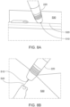
- FIG. 8A illustrates the welding torch 220 as corrected to the ideal push angle of 10 degrees, with respect to the joint/seam 520 of the work piece 530, by the robot of the welding system 100.
- FIG. 8B illustrates the welding torch 220 of FIG. 8A as corrected to the ideal work angle of 45 degrees, with respect to the joint/seam 520 of the work piece 530, by the robot of the welding system 100.
- the weld angle correction tool 400 operates with the robotic welding system 100 in real time when teaching the robot. In this manner, a user can position the tip of a welding torch at a desired weld point in a weld joint/seam, and then use the weld angle correction tool 400 to adjust the angles of the welding torch to the ideal angles for that type of work piece having a particular type of weld joint/seam. Therefore, the user of the welding system does not have to have detailed welding knowledge of how to set the various angles of the welding torch.
- FIG. 9 is a flow chart of an embodiment of a method 900 of correcting welding torch angles using the weld angle correction tool 400 of FIG. 2 as operatively integrated with the welding system 100 of FIG. 1 .
- a single stereoscopic depth image is used to reliably locate planes, plane intersections, and the extents of the plane intersection lines of the weldment and corresponding joint/seam in the 3D robot coordinate space.
- the weld angle correction tool uses one seam with two plane normals to calculate and display the current work angle, as set by the user, and also find the ideal work angle with respect to the joint/seam.
- step 910 of the method 900 stereoscopic image data of a weldment and its corresponding weld joint/seam are acquired using a depth camera of a weld angle correction tool.
- a computer of the weld angle correction tool takes the stereoscopic image data and generates 3D point cloud data representing the weldment and its corresponding weld joint/seam in robot coordinate space.
- the computer of the weld angle correction tool processes the 3D point cloud data to generate 3D plane and intersection data representative of the weldment and its corresponding weld joint/seam in robot coordinate space.
- the computer of the weld angle correction tool imports 3D torch position an orientation data from the robot controller.
- the 3D torch position and orientation data represent the position and orientation of the welding torch as positioned by the user at a recorded weld point along the weld joint/seam, in robot coordinate space.
- the computer of the weld angle correction tool calculates a torch push angle and a torch work angle at the recorded weld point with respect to the weldment and its weld joint/seam in robot coordinate space.
- the computer of the weld angle correction tool uses the user-placed torch position and orientation data and the 3D plane and intersection data of the weldment and weld joint/seam to calculate the torch push angle and the torch work angle.
- the robot controller when commanded by the user via the weld angle correction tool, corrects the torch push angle and the torch weld angle at the recorded weld point with respect to the weldment and weld joint/seam based on pre-stored ideal angles for the weldment and its weld joint/seam.
- the ideal angles are stored in the robot controller, in accordance with one embodiment.
- weld points can be defined by pointing the depth camera at the weld joint/seam and "clicking" on a point instead of moving the welding torch into the weld joint/seam.
- the welding wire of the welding torch can be fully retracted and weld points can be taught to the system with the correct stickout using the depth camera, thus preventing the wire from being bent during teaching.
- Two-dimensional (2D) and three-dimensional (3D) wire search motion can be automatically defined using the detected planes. Inside corners at the start and end of a fillet weld can be detected and push angles can be modified to avoid crashing the robot into the weldment.
- the need for expensive, custom part fixturing can be eliminated by using AR guides to show the user where to place a part in front of the robot, and using the depth camera to teach features that accurately locate the part in space.
- finding the intersection of three (3) seams can be used to quickly teach a part work object frame, allowing for easy program re-use between different robots, or making multiples of the same part.
- small lap-joint seams can be detected and characterized using data acquired by the depth camera and an associated algorithm.
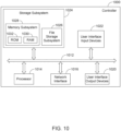
- FIG. 10 illustrates a block diagram of an example embodiment of a controller 1000 that can be used, for example, in the welding system 100 of FIG. 1 .
- the controller 1000 may be used as the robot controller 320 and/or as a controller in the welding power supply 310.
- the controller 1000 may be representative of the laptop computer 420 of FIG. 2 , or of other computer platforms in other embodiments that perform much of the functionality of the weld angle correction tool 400.
- the controller 1000 includes at least one processor 1014 (e.g., a microprocessor, a central processing unit, a graphics processing unit) which communicates with a number of peripheral devices via bus subsystem 1012.
- peripheral devices may include a storage subsystem 1024, including, for example, a memory subsystem 1028 and a file storage subsystem 1026, user interface input devices 1022, user interface output devices 1020, and a network interface subsystem 1016.
- the input and output devices allow user interaction with the controller 1000.
- Network interface subsystem 1016 provides an interface to outside networks and is coupled to corresponding interface devices in other devices.
- User interface input devices 1022 may include a keyboard, pointing devices such as a mouse, trackball, touchpad, or graphics tablet, a scanner, a touchscreen incorporated into the display, audio input devices such as voice recognition systems, microphones, and/or other types of input devices.
- pointing devices such as a mouse, trackball, touchpad, or graphics tablet
- audio input devices such as voice recognition systems, microphones, and/or other types of input devices.
- use of the term "input device” is intended to include all possible types of devices and ways to input information into the controller 1000 or onto a communication network.
- User interface output devices 1020 may include a display subsystem, a printer, or non-visual displays such as audio output devices.
- the display subsystem may include a cathode ray tube (CRT), a flat-panel device such as a liquid crystal display (LCD), a projection device, or some other mechanism for creating a visible image.
- the display subsystem may also provide non-visual display such as via audio output devices.
- output device is intended to include all possible types of devices and ways to output information from the controller 1000 to the user or to another machine or computer system.
- Storage subsystem 1024 stores programming and data constructs that provide some or all of the functionality described herein.
- Computer-executable instructions and data are generally executed by processor 1014 alone or in combination with other processors.
- Memory 1028 used in the storage subsystem 1024 can include a number of memories including a main random access memory (RAM) 1030 for storage of instructions and data during program execution and a read only memory (ROM) 1032 in which fixed instructions are stored.
- a file storage subsystem 1026 can provide persistent storage for program and data files, and may include a hard disk drive, a solid state drive, a floppy disk drive along with associated removable media, a CD-ROM drive, an optical drive, or removable media cartridges.
- the computer-executable instructions and data implementing the functionality of certain embodiments may be stored by file storage subsystem 1026 in the storage subsystem 1024, or in other machines accessible by the processor(s) 1014.
- Bus subsystem 1012 provides a mechanism for letting the various components and subsystems of the controller 1000 communicate with each other as intended. Although bus subsystem 1012 is shown schematically as a single bus, alternative embodiments of the bus subsystem may use multiple buses.
- the controller 1000 can be of varying types. Due to the ever-changing nature of computing devices and networks, the description of the controller 1000 depicted in FIG. 10 is intended only as a specific example for purposes of illustrating some embodiments. Many other configurations of a controller are possible, having more or fewer components than the controller 1000 depicted in FIG. 10 .
Landscapes
- Engineering & Computer Science (AREA)
- Mechanical Engineering (AREA)
- Robotics (AREA)
- Physics & Mathematics (AREA)
- General Physics & Mathematics (AREA)
- Computer Vision & Pattern Recognition (AREA)
- Theoretical Computer Science (AREA)
- Optics & Photonics (AREA)
- Human Computer Interaction (AREA)
- Automation & Control Theory (AREA)
- Numerical Control (AREA)
- Manipulator (AREA)
Abstract
Description
- This U.S. Patent Application claims priority to and the benefit of
U.S. Provisional Patent Application serial number 63/349,180 filed on June 6, 2022 U.S. Published Patent Application No. 2020/0139474 A1 is incorporated herein by reference it its entirety.U.S. Patent No. 9,833,857 B2 - Embodiments of the present invention relate to the use of robots (e.g., collaborative robots or cobots) for welding or cutting. More specifically, embodiments of the present invention relate to a welding angle correction tool and method for correcting recorded robot welding/cutting torch orientations as positioned by a human user when training a robot to traverse a weld joint.
- Programming motion trajectories of a robot (e.g., a collaborative robot) prior to actual welding or cutting can be quite complicated. In addition to the challenges associated with programming a weld trajectory along a weld joint, other challenges exist that are associated with setting and programming angles and orientations of a welding or cutting torch at points along the trajectory.
- A robotic welding or cutting system is configured to allow a human user to train a robot of the system by positioning a welding or cutting torch attached to an arm of the robot at various points along a joint/seam of a weldment to be welded or cut. The user, preferably via a user interface, moves the arm of the robot to position a tip of the torch at a desired point along the joint/seam and the point is recorded by the robot controller (i.e., the robot controller records the spatial coordinates and angular orientations of the torch at the point). In accordance with an embodiment of the present invention, the user does not have to be particularly careful about how the angles (e.g., a push angle and a work angle) of the torch are positioned by the user with respect to the weldment and corresponding joint/seam. The weld angle correction tool includes a depth camera that acquires stereoscopic depth image data which is used to determine the actual torch angles of the torch, as positioned by the user, with respect to the joint/seam. Once the user has positioned the torch and recorded the corresponding desired points along the joint, the user can activate a weld angle correction tool to select a recorded point and make corrections to the recorded parameters (e.g., push angle and work angle) associated with that point.
- In one embodiment, a method of correcting angles of a welding torch positioned by a user while training a robot of a robotic welding system is provided. Stereoscopic image data of a weldment and a corresponding weld seam is acquired and 3D point cloud data is generated. 3D plane and intersection data is generated from the 3D point cloud data, representing the weldment and weld seam. User-placed 3D torch position and orientation data for a recorded weld point along the weld seam is imported. A torch push angle and a torch work angle are calculated for the recorded weld point, with respect to the weldment and weld seam, based on the user-placed torch position and orientation data and the 3D plane and intersection data. The torch push angle and the torch work angle are corrected for the recorded weld point based on pre-stored ideal angles for the weld seam.
- In one embodiment, a method of correcting angles of a welding torch positioned by a user is provided. Any of the disclosed methods herein allow correcting of angles of a welding torch. The method can be performed during training of a robot of a robotic welding system. A training setting can comprise any setting in which there is feedback. A robot of a robotic welding system can include a computer with a processor and instructions performed thereon. The method includes acquiring weldment depth data of a weldment and a corresponding weld seam using a depth camera of a weld angle correction tool, and processing the weldment depth data using a computer of the weld angle correction tool. A single image of weldment depth data of the weldment and corresponding weld seam can be acquired. In one embodiment, the weldment depth data is stereoscopic image data. In one embodiment, the computer of the weld angle correction tool uses matrix manipulation techniques, point cloud manipulation techniques, and feature recognition techniques as part of processing the weldment depth data. The weldment depth data of weldment and weld seam represent physical data of the weldment and weld seam.
- The method also includes importing user-placed 3D torch position and orientation data to the computer of the weld angle correction tool from a robot controller of a robotic welding system in a robot coordinate space for a recorded weld point along the corresponding weld seam. The method further includes calculating, using the computer of the weld angle correction tool, at least one torch angle for the recorded weld point with respect to the weldment and the corresponding weld seam in the robot coordinate space based on the weldment depth data of the weldment and the corresponding weld seam, as processed by the computer of the weld angle correction tool, and the user-placed 3D torch position and orientation data. The method also includes correcting the at least one torch angle for the recorded weld point based on pre-stored ideal angles for the weldment and the corresponding weld seam. In one embodiment, the processing of the weldment depth data includes generating 3D point cloud data from the stereoscopic image data in the robot coordinate space using the computer of the weld angle correction tool. In one embodiment, the processing of the weldment depth data includes generating 3D plane and intersection data representative of the weldment and the corresponding weld seam from the 3D point cloud data in the robot coordinate space using the computer of the weld angle correction tool. The torch angle may include, for example, a torch push angle and/or a torch work angle. In one embodiment, the weldment depth data is transmitted via at least one of a wired or a wireless means from the depth camera to the computer of the weld angle correction tool. In one embodiment, the user-placed 3D torch position and orientation data is transmitted via at least one of a wired or a wireless means from the robot controller to the computer of the weld angle correction tool. In one embodiment, a position of the depth camera is calibrated to one of a tip of the welding torch or a tool center point (TCP) of the robot.
- In one embodiment, a weld angle correction tool for correcting angles of a welding torch positioned by a user while training a robot of a robotic welding system is provided. The weld angle correction tool includes a depth camera configured to acquire weldment depth data of a weldment and a corresponding weld seam to be welded by a robotic welding system having a welding torch. The weld angle correction tool also includes a computer device configured to receive the weldment depth data from the depth camera, and user-placed 3D torch position and orientation data from a robot controller of the robotic welding system for a recorded weld point along the corresponding weld seam. The computer device is further configured to calculate at least one torch angle of the welding torch for the recorded weld point with respect to the weldment and the corresponding weld seam in a coordinate space of the robotic welding system based on the weldment depth data and the user-placed torch position and orientation data. The computer device is also configured to calculate at least one corrected torch angle based on the at least one torch angle for the recorded weld point, as calculated, and pre-stored ideal angles for the weldment and the corresponding weld seam. In one embodiment, the weldment depth data is stereoscopic image data. In one embodiment, the depth camera includes two imaging apertures for acquiring the stereoscopic image data. In one embodiment, calculating of the at least one torch angle using the computer device includes generating 3D point cloud data from the stereoscopic image data in the coordinate space of the robotic welding system. In one embodiment, calculating of the at least one torch angle using the computer device includes generating 3D plane and intersection data representative of the weldment and the corresponding weld seam from the 3D point cloud data in the coordinate space of the robotic welding system. In one embodiment, the computer device is in the form of a laptop computer. In one embodiment, the computer device is integrated into the robot controller of the robotic welding system. In one embodiment, the computer device is integrated into a welding power supply of the robotic welding system. In one embodiment, the depth camera is configured to be removably attached to the welding torch. In one embodiment, the depth camera is configured to be mounted on joint 6 of a robot arm of the robotic welding system.
- Numerous aspects of the general inventive concepts will become readily apparent from the following detailed description of exemplary embodiments, from the claims, and from the accompanying drawings.
- The accompanying drawings, which are incorporated in and constitute a part of the specification, illustrate various embodiments of the disclosure. It will be appreciated that the illustrated element boundaries (e.g., boxes, groups of boxes, or other shapes) in the figures represent one embodiment of boundaries. In some embodiments, one element may be designed as multiple elements or multiple elements may be designed as one element. In some embodiments, an element shown as an internal component of another element may be implemented as an external component and vice versa. Furthermore, elements may not be drawn to scale.
-
FIG. 1 illustrates one embodiment of a welding system having a robot (e.g., a collaborative robot); -
FIG. 2 illustrates one embodiment of a weld angle correction tool; -
FIG. 3 illustrates a robot portion of the welding system ofFIG. 1 operatively integrated with the weld angle correction tool ofFIG. 2 ; -
FIG. 4 illustrates a schematic block diagram of data inputs to and data outputs from an algorithm of the weld angle correction tool ofFIG. 2 when operating with the welding system ofFIG. 1 ; -
FIG. 5A illustrates a welding torch of the welding system that has been positioned by a user at a desired weld point at a joint/seam of a work piece at a non-ideal push angle; -
FIG. 5B illustrates the welding torch ofFIG. 5A that has been positioned by the user at the desired weld point of the joint/seam of the work piece at a non-ideal work angle; -
FIG. 6 illustrates a camera view, provided by the weld angle correction tool ofFIG. 2 , of the work piece and corresponding j oint/seam showing the non-deal angles of the welding torch, before angle correction, in an augmented reality manner; -
FIG. 7 illustrates the camera view, provided by the weld angle correction tool ofFIG. 2 , of the work piece and corresponding joint/seam showing the corrected/ideal angles of the welding torch, after angle correction, in an augmented reality manner; -
FIG. 8A illustrates the welding torch as corrected to the corrected/ideal push angle, with respect to the j oint/seam of the work piece, by the robot of the welding system; -
FIG. 8B illustrates the welding torch ofFIG. 8A as corrected to the corrected ideal work angle, with respect to the j oint/seam of the work piece, by the robot of the welding system; -
FIG. 9 is a flow chart of an embodiment of a method of correcting welding torch angles using the weld angle correction tool ofFIG. 2 as operatively integrated with the welding system ofFIG. 1 ; and -
FIG. 10 illustrates a block diagram of an example embodiment of a controller that can be used, for example, in the welding system ofFIG. 1 . - The examples and figures herein are illustrative only and are not meant to limit the subj ect invention, which is measured by the scope and spirit of the claims. Referring now to the drawings, wherein the showings are for the purpose of illustrating exemplary embodiments of the subject invention only and not for the purpose of limiting same,
FIG. 1 illustrates one embodiment of awelding system 100 having a robot portion 200 (e.g., a collaborative robot). Although the discussion herein focuses on a welding system, the inventive concepts herein can apply equally well to a cutting system (e.g., a robotic plasma cutting system). Referring toFIG. 1 , thewelding system 100 includes arobot portion 200, awelding power supply 310, and arobot controller 320. Therobot portion 200 has anarm 210 configured to hold a welding torch (e.g., a welding gun) 220. The terms "torch" and "gun" are used herein interchangeably. Therobot portion 200 also includes a servo-mechanism apparatus 230 configured to move thearm 210 of therobot portion 200 under the command of therobot controller 320. In one embodiment, thewelding system 100 includes a wire feeder (not shown) to feed consumable welding wire to thewelding torch 220. -
FIG. 2 illustrates one embodiment of a weldangle correction tool 400. The weldangle correction tool 400 includes adepth camera 410 and a computer device (e.g., a lap top computer 420). Thedepth camera 410 has twoimaging apertures 411 and 412 and is configured to acquire stereoscopic image data. The stereoscopic image data allows the depths of points in space to be determined. The stereoscopic image data is transmitted (via wired or wireless means) from thedepth camera 410 to thelaptop computer 420. As discussed later herein, thelaptop computer 420 is programmed to convert the stereoscopic image data to 3D point cloud data, and then generate 3D plane/intersection data from the 3D point cloud data in the coordinate space of the robot (the robot coordinate space). In other embodiments, an alternative coordinate space may be defined and used. - When the user positions the
robot arm 210 having thewelding torch 220 connected thereto at a desired weld point of a weld joint/seam of a weldment (work piece), therobot controller 320 records the corresponding torch position and orientation data. The terms "weldment" and "work piece" are used interchangeably herein. Therobot controller 320 transmits (via wired or wireless means) the user-placed torch position and orientation data, in the coordinate space of the robot, to thelaptop computer 420. In accordance with other embodiments, thelaptop computer 420 may be some other type of computer device or controller (e.g., having at least one processor) in some other form. In one embodiment, the functionality of the laptop computer may be integrated into therobot controller 320, or in another embodiment, into thewelding power supply 310. -
FIG. 3 illustrates arobot portion 200 of thewelding system 100 ofFIG. 1 operatively integrated with the weldangle correction tool 400 ofFIG. 2 . In the embodiment ofFIG. 3 , thedepth camera 410 is mounted (e.g., removably attached to) thewelding torch 220 behind a gas nozzle of thewelding torch 220. In this manner, when thewelding torch 220 is positioned at a desired weld point at a weld joint/seam of a weldment, the field of view of thedepth camera 410 will include the weld point and a portion of the weldment (along with its weld joint/seam) surrounding the weld point. In another embodiment, thedepth camera 410 may be mounted on joint 6 of the robot arm 210 (near a distal end of the robot arm 210). Other mounting positions are possible as well, in accordance with other embodiments. In the embodiment ofFIG. 3 , thelaptop computer 420 communicates wirelessly (e.g., via Bluetooth® or Wi-Fi) with thedepth camera 410 and therobot controller 320. In accordance with one embodiment, the position of thedepth camera 410 is calibrated to, for example, the tip of the torch or a tool center point (TCP) of the robot (e.g., using an eye-hand calibration software). Thedepth camera 410 may be "hardened" to survive the welding environment. -
FIG. 4 illustrates a schematic block diagram of data inputs to and data outputs from an algorithm 425 (or a set of algorithms or processes implemented in software and/or hardware) on thelaptop computer 420 of the weldangle correction tool 400 ofFIG. 2 when operating with thewelding system 100 ofFIG. 1 . Thealgorithm 425 operates on two sets of input data being that of weldment j oint/seam stereoscopic image data (depth data) from thedepth camera 410 and robot torch position and orientation data from therobot controller 320. Thealgorithm 425 is programmed to convert the depth data to 3D point cloud data, and then generate 3D plane/intersection data from the 3D point cloud data in the coordinate space of the robot, for example. In accordance with one embodiment, thealgorithm 425 uses matrix manipulation techniques, point cloud manipulation techniques, and feature recognition techniques. Upon operating on the two sets of input data (the depth data and the torch position/orientation data), thealgorithm 425 generates a torch push angle and a torch work angle with respect to the weld joint/seam in the coordinate space of the robot. One skilled in the art of arc welding will understand the concepts of a torch push angle and a torch work angle. - The acquired depth data (in a single stereoscopic image) allows the weld
angle correction tool 400 to determine, in three-dimensional detail, characteristics of the weldment joint/seam (i.e., what the geometry of weldment joint/seam looks like). Processing of the acquired depth data eliminates any need to use a touch-sensing technique to determine the geometry of the weldment joint/seam. Also, therobot controller 320 "knows" the recorded position and orientation of the torch with respect to the robot coordinate system, but not with respect to the position and orientation of the weldment/work piece. Together, both the depth data and the robot torch position/orientation data allow the actual torch angles, as positioned by the user, to be determined. Other torch parameters (e.g., a stickout distance) may be determined from the weldment j oint/seam depth data and/or the robot torch position/orientation data, in accordance with other embodiments. - As an example,
FIG. 5A illustrates awelding torch 220 of thewelding system 100 that has been positioned by a user at a desired weld point 510 (which is recorded by the robot controller 320) at a joint/seam 520 of a work piece (weldment) 530. The welding torch is at a non-ideal push angle. Similarly,FIG. 5B illustrates thewelding torch 220 ofFIG. 5A that has been positioned by the user at the desiredweld point 510 of the joint/seam 520 of thework piece 530 at a non-ideal work angle. - In one embodiment, the
depth camera 410 is also configured to provide a regular camera view (e.g., using only one image aperture of the two image apertures of the depth camera 410). For example,FIG. 6 illustrates a camera view 600 (provided by the weldangle correction tool 400 ofFIG. 2 via the camera 410) of thework piece 530 and the corresponding j oint/seam 520 showing the non-ideal angles of thewelding torch 220, in an augmented reality manner, before angle correction has been performed. Thecamera view 600 is displayed on adisplay device 422 of thelaptop computer 420. TheAR reticle symbol 610 shows the location of the recordedweld point 510 with respect to thework piece 530 and the corresponding joint/seam 520. The work angle (represented by AR symbol 615) of the welding torch 220 (as positioned by the user and computed by the algorithm 425) is 61 degrees (non-ideal). The push angle (represented by AR symbol 617) of the welding torch 220 (as positioned by the user and computed by the algorithm 425) is -22 degrees (non-ideal). In this manner, a user can view thecamera view 600 on adisplay device 422 of thelaptop computer 420 along withAR symbols weld point 510 and the non-ideal work and push angles. Thecomputer 420 is configured (e.g., via hardware and software) to command the displaying of the various augmented reality symbols on thedisplay device 422. -
FIG. 7 illustrates thecamera view 600, provided by the weldangle correction tool 400 ofFIG. 2 , of thework piece 530 and the corresponding joint/seam 520 showing the corrected angles of thewelding torch 220, in an augmented reality manner, after angle correction. For example, in one embodiment, the user selects thereticle symbol 610 in the camera view 600 (e.g., using a user interface 427 (e.g., a computer keyboard or a computer mouse) of thelaptop computer 420. The user then commands the system (e.g., via a CNTL F command on the keyboard of the laptop computer 420) to correct the push angle and the work angle of thewelding torch 220 at theweld point 510 to the ideal angles for the type ofwork piece 530 and joint/seam 520 with respect to the characteristics of thework piece 530 and joint/seam 520 (as characterized by the weld angle correction tool 400). The AR symbology now shows the correctedwork angle symbol 615 representing 45 degrees, and the correctedpush angle symbol 617 representing 10 degrees inFIG. 7 . - The
robot controller 320 "knows" the type of work piece and joint/seam. For example, in one embodiment, the workangle correction tool 400 determines the type of work piece and joint/seam from the 3D point cloud data and informs therobot controller 320. The ideal angles are computed by thecomputer 420 of the weldangle correction tool 400 based on at least the weldment depth data, in one embodiment. In another embodiment, the type of work piece and joint/seam (along with ideal angles) is pre-stored in therobot controller 320. Thelaptop computer 420 communicates with therobot controller 320, and therobot controller 320 changes the recorded work angle (with respect to the work piece and joint/seam) to the ideal work angle of 45 degrees, and the recorded push angle (with respect to the work piece and j oint/seam) to the ideal push angle of 10 degrees (as seen in thecamera view 600 ofFIG. 7 ). - The
robot controller 320 may then command therobot arm 210 to re-position thewelding torch 220 at theweld point 510, but with the corrected angles of 45 degrees and 10 degrees.FIG. 8A illustrates thewelding torch 220 as corrected to the ideal push angle of 10 degrees, with respect to the joint/seam 520 of thework piece 530, by the robot of thewelding system 100.FIG. 8B illustrates thewelding torch 220 ofFIG. 8A as corrected to the ideal work angle of 45 degrees, with respect to the joint/seam 520 of thework piece 530, by the robot of thewelding system 100. - The weld
angle correction tool 400 operates with therobotic welding system 100 in real time when teaching the robot. In this manner, a user can position the tip of a welding torch at a desired weld point in a weld joint/seam, and then use the weldangle correction tool 400 to adjust the angles of the welding torch to the ideal angles for that type of work piece having a particular type of weld joint/seam. Therefore, the user of the welding system does not have to have detailed welding knowledge of how to set the various angles of the welding torch. -
FIG. 9 is a flow chart of an embodiment of amethod 900 of correcting welding torch angles using the weldangle correction tool 400 ofFIG. 2 as operatively integrated with thewelding system 100 ofFIG. 1 . In general, a single stereoscopic depth image is used to reliably locate planes, plane intersections, and the extents of the plane intersection lines of the weldment and corresponding joint/seam in the 3D robot coordinate space. For example, in one embodiment, the weld angle correction tool uses one seam with two plane normals to calculate and display the current work angle, as set by the user, and also find the ideal work angle with respect to the joint/seam. - In
step 910 of themethod 900, stereoscopic image data of a weldment and its corresponding weld joint/seam are acquired using a depth camera of a weld angle correction tool. Instep 920 of themethod 900, a computer of the weld angle correction tool takes the stereoscopic image data and generates 3D point cloud data representing the weldment and its corresponding weld joint/seam in robot coordinate space. Instep 930 of themethod 900, the computer of the weld angle correction tool processes the 3D point cloud data to generate 3D plane and intersection data representative of the weldment and its corresponding weld joint/seam in robot coordinate space. - In
step 940 of themethod 900, the computer of the weld anglecorrection tool imports 3D torch position an orientation data from the robot controller. The 3D torch position and orientation data represent the position and orientation of the welding torch as positioned by the user at a recorded weld point along the weld joint/seam, in robot coordinate space. Atstep 950 of themethod 900, the computer of the weld angle correction tool calculates a torch push angle and a torch work angle at the recorded weld point with respect to the weldment and its weld joint/seam in robot coordinate space. The computer of the weld angle correction tool uses the user-placed torch position and orientation data and the 3D plane and intersection data of the weldment and weld joint/seam to calculate the torch push angle and the torch work angle. Atstep 960 of themethod 900, the robot controller, when commanded by the user via the weld angle correction tool, corrects the torch push angle and the torch weld angle at the recorded weld point with respect to the weldment and weld joint/seam based on pre-stored ideal angles for the weldment and its weld joint/seam. The ideal angles are stored in the robot controller, in accordance with one embodiment. - Other embodiments can provide additional capability as well. For example, in one embodiment, weld points can be defined by pointing the depth camera at the weld joint/seam and "clicking" on a point instead of moving the welding torch into the weld joint/seam. Furthermore, in a teach mode, the welding wire of the welding torch can be fully retracted and weld points can be taught to the system with the correct stickout using the depth camera, thus preventing the wire from being bent during teaching. Two-dimensional (2D) and three-dimensional (3D) wire search motion can be automatically defined using the detected planes. Inside corners at the start and end of a fillet weld can be detected and push angles can be modified to avoid crashing the robot into the weldment. The need for expensive, custom part fixturing can be eliminated by using AR guides to show the user where to place a part in front of the robot, and using the depth camera to teach features that accurately locate the part in space. In one embodiment, finding the intersection of three (3) seams can be used to quickly teach a part work object frame, allowing for easy program re-use between different robots, or making multiples of the same part. In one embodiment, small lap-joint seams can be detected and characterized using data acquired by the depth camera and an associated algorithm.
-
FIG. 10 illustrates a block diagram of an example embodiment of acontroller 1000 that can be used, for example, in thewelding system 100 ofFIG. 1 . For example, thecontroller 1000 may be used as therobot controller 320 and/or as a controller in thewelding power supply 310. Furthermore, thecontroller 1000 may be representative of thelaptop computer 420 ofFIG. 2 , or of other computer platforms in other embodiments that perform much of the functionality of the weldangle correction tool 400. - Referring to
FIG. 10 , thecontroller 1000 includes at least one processor 1014 (e.g., a microprocessor, a central processing unit, a graphics processing unit) which communicates with a number of peripheral devices viabus subsystem 1012. These peripheral devices may include astorage subsystem 1024, including, for example, amemory subsystem 1028 and afile storage subsystem 1026, userinterface input devices 1022, userinterface output devices 1020, and anetwork interface subsystem 1016. The input and output devices allow user interaction with thecontroller 1000.Network interface subsystem 1016 provides an interface to outside networks and is coupled to corresponding interface devices in other devices. - User
interface input devices 1022 may include a keyboard, pointing devices such as a mouse, trackball, touchpad, or graphics tablet, a scanner, a touchscreen incorporated into the display, audio input devices such as voice recognition systems, microphones, and/or other types of input devices. In general, use of the term "input device" is intended to include all possible types of devices and ways to input information into thecontroller 1000 or onto a communication network. - User
interface output devices 1020 may include a display subsystem, a printer, or non-visual displays such as audio output devices. The display subsystem may include a cathode ray tube (CRT), a flat-panel device such as a liquid crystal display (LCD), a projection device, or some other mechanism for creating a visible image. The display subsystem may also provide non-visual display such as via audio output devices. In general, use of the term "output device" is intended to include all possible types of devices and ways to output information from thecontroller 1000 to the user or to another machine or computer system. -
Storage subsystem 1024 stores programming and data constructs that provide some or all of the functionality described herein. For example, computer-executable instructions and data are generally executed byprocessor 1014 alone or in combination with other processors.Memory 1028 used in thestorage subsystem 1024 can include a number of memories including a main random access memory (RAM) 1030 for storage of instructions and data during program execution and a read only memory (ROM) 1032 in which fixed instructions are stored. Afile storage subsystem 1026 can provide persistent storage for program and data files, and may include a hard disk drive, a solid state drive, a floppy disk drive along with associated removable media, a CD-ROM drive, an optical drive, or removable media cartridges. The computer-executable instructions and data implementing the functionality of certain embodiments may be stored byfile storage subsystem 1026 in thestorage subsystem 1024, or in other machines accessible by the processor(s) 1014. -
Bus subsystem 1012 provides a mechanism for letting the various components and subsystems of thecontroller 1000 communicate with each other as intended. Althoughbus subsystem 1012 is shown schematically as a single bus, alternative embodiments of the bus subsystem may use multiple buses. - The
controller 1000 can be of varying types. Due to the ever-changing nature of computing devices and networks, the description of thecontroller 1000 depicted inFIG. 10 is intended only as a specific example for purposes of illustrating some embodiments. Many other configurations of a controller are possible, having more or fewer components than thecontroller 1000 depicted inFIG. 10 . - While the disclosed embodiments have been illustrated and described in considerable detail, it is not the intention to restrict or in any way limit the scope of the appended claims to such detail. It is, of course, not possible to describe every conceivable combination of components or methodologies for purposes of describing the various aspects of the subject matter. Therefore, the disclosure is not limited to the specific details or illustrative examples shown and described. Thus, this disclosure is intended to embrace alterations, modifications, and variations that fall within the scope of the appended claims, which satisfy the statutory subject matter requirements of 35 U.S.C. §101. The above description of specific embodiments has been given by way of example. From the disclosure given, those skilled in the art will not only understand the general inventive concepts and attendant advantages, but will also find apparent various changes and modifications to the structures and methods disclosed. It is sought, therefore, to cover all such changes and modifications as fall within the spirit and scope of the general inventive concepts, as defined by the appended claims, and equivalents thereof.
Claims (15)
- A method of correcting angles of a welding torch positioned by a user while training a
robot of a robotic welding system, the method comprising:acquiring a single image of weldment depth data of a weldment and a corresponding weld seam using a depth camera of a weld angle correction tool;processing the weldment depth data using the computer of the weld angle correction tool;importing user-placed 3D torch position and orientation data to the computer of the weld angle correction tool from a robot controller of a robotic welding system in a robot coordinate space for a recorded weld point along the corresponding weld seam;calculating, using the computer of the weld angle correction tool, at least one torch angle for the recorded weld point with respect to the weldment and the corresponding weld seam in the robot coordinate space based on the weldment depth data of the weldment and the corresponding weld seam, as processed by the computer of the weld angle correction tool, and the user-placed 3D torch position and orientation data; andcorrecting the at least one torch angle for the recorded weld point based on pre-stored ideal angles for the weldment and the corresponding weld seam. - The method of claim 1, wherein the weldment depth data is stereoscopic image data.
- The method of claim 2, wherein the processing of the weldment depth data includes generating 3D point cloud data from the stereoscopic image data in the robot coordinate space using the computer of the weld angle correction tool, wherein preferably the processing of the weldment depth data includes generating 3D plane and intersection data representative of the weldment and the corresponding weld seam from the 3D point cloud data in the robot coordinate space using the computer of the weld angle correction tool.
- The method of any of the previous claims, wherein the at least one torch angle includes a torch push angle and/or a torch work angle.
- The method of any of the previous claims, wherein the weldment depth data is transmitted via at least one of a wired or a wireless means from the depth camera to the computer of the weld angle correction tool.
- The method of any of the previous claims, wherein the user-placed 3D torch position and orientation data is transmitted via at least one of a wired or a wireless means from the robot controller to the computer of the weld angle correction tool.
- The method of any of the previous claims, wherein a position of the depth camera is calibrated to one of a tip of the welding torch or a tool center point (TCP) of the robot.
- The method of any of the previous claims, wherein the computer of the weld angle correction tool uses matrix manipulation techniques, point cloud manipulation techniques, and feature recognition techniques as part of processing the weldment depth data.
- A weld angle correction tool for correcting angles of a welding torch positioned by a user
while training a robot of a robotic welding system, the weld angle correction tool comprising:a depth camera configured to acquire a single image of weldment depth data of a weldment and a corresponding weld seam to be welded by a robotic welding system having a welding torch; anda computer device configured to receive:the weldment depth data from the depth camera, anduser-placed 3D torch position and orientation data from a robot controller of the robotic welding system for a recorded weld point along the corresponding weld seam,wherein the computer device is configured to:calculate at least one torch angle of the welding torch for the recorded weld point with respect to the weldment and the corresponding weld seam in a coordinate space of the robotic welding system based on the weldment depth data and the user-placed torch position and orientation data, andcalculate at least one corrected torch angle based on the at least one torch angle for the recorded weld point, as calculated, and pre-stored ideal angles for the weldment and the corresponding weld seam. - The weld angle correction tool of claim 9, wherein the weldment depth data is stereoscopic image data.
- The weld angle correction tool of claim 10, wherein calculating of the at least one torch angle using the computer device includes generating 3D point cloud data from the stereoscopic image data in the coordinate space of the robotic welding system, wherein preferably calculating of the at least one torch angle using the computer device includes generating 3D plane and intersection data representative of the weldment and the corresponding weld seam from the 3D point cloud data in the coordinate space of the robotic welding system.
- The weld angle correction tool of any of the claims 9-11, wherein the computer device is in the form of a laptop computer.
- The weld angle correction tool of any of the claims 9-12, wherein the computer device is integrated into the robot controller of the robotic welding system and/or into a welding power supply of the robotic welding system.
- The weld angle correction tool of any of the claims 9-13, wherein the depth camera is configured to be removably attached to the welding torch or is configured to be mounted on joint 6 of a robot arm of the robotic welding system.
- The weld angle correction tool of any of the claims 9-14, wherein the depth camera includes two imaging apertures for acquiring stereoscopic image data.
Applications Claiming Priority (2)
| Application Number | Priority Date | Filing Date | Title |
|---|---|---|---|
| US202263349180P | 2022-06-06 | 2022-06-06 | |
| US17/978,342 US12208530B2 (en) | 2022-06-06 | 2022-11-01 | Weld angle correction device |
Publications (1)
| Publication Number | Publication Date |
|---|---|
| EP4289567A1 true EP4289567A1 (en) | 2023-12-13 |
Family
ID=86692731
Family Applications (1)
| Application Number | Title | Priority Date | Filing Date |
|---|---|---|---|
| EP23177412.6A Pending EP4289567A1 (en) | 2022-06-06 | 2023-06-05 | Weld angle correction device |
Country Status (3)
| Country | Link |
|---|---|
| US (1) | US12208530B2 (en) |
| EP (1) | EP4289567A1 (en) |
| CN (1) | CN117182405B (en) |
Families Citing this family (4)
| Publication number | Priority date | Publication date | Assignee | Title |
|---|---|---|---|---|
| KR102582166B1 (en) * | 2023-06-08 | 2023-09-25 | 주식회사 한다랩 | Pick Up System of Autonomous Charging Robot for Electric Vehicle |
| JP2025001948A (en) * | 2023-06-21 | 2025-01-09 | 株式会社神戸製鋼所 | Workpiece measurement method and welding system |
| CN118840642B (en) * | 2024-06-27 | 2025-10-17 | 华南理工大学 | Robot welding arc blow angle identification method, medium and equipment |
| CN119734260A (en) * | 2024-12-11 | 2025-04-01 | 上海船舶工艺研究所(中国船舶集团有限公司第十一研究所) | A teaching-free system programming method for welding robots with arbitrary workpiece placement |
Citations (6)
| Publication number | Priority date | Publication date | Assignee | Title |
|---|---|---|---|---|
| US5799135A (en) * | 1994-06-28 | 1998-08-25 | Fanuc, Ltd. | Robot controlling method and apparatus using laser sensor |
| US5845053A (en) * | 1994-10-25 | 1998-12-01 | Fanuc Ltd. | Method for teaching welding torch orientation |
| EP2375298A2 (en) * | 2010-03-29 | 2011-10-12 | Daihen Corporation | Programming method for a robot, programming apparatus for a robot, and robot control system |
| US20200114449A1 (en) * | 2018-10-12 | 2020-04-16 | Teradyne, Inc. | System and method for weld path generation |
| US20210138646A1 (en) * | 2019-11-07 | 2021-05-13 | Fanuc Corporation | Controller for determining modification method of position or orientation of robot |
| WO2022016152A1 (en) * | 2020-07-17 | 2022-01-20 | Path Robotics, Inc. | Real time feedback and dynamic adjustment for welding robots |
Family Cites Families (41)
| Publication number | Priority date | Publication date | Assignee | Title |
|---|---|---|---|---|
| US4118620A (en) | 1977-05-20 | 1978-10-03 | Lovelace Alan M Acting Adminis | Computerized system for translating a torch head |
| JPS55136575A (en) | 1979-04-09 | 1980-10-24 | Daikin Ind Ltd | Tracing welding equipment |
| US4750663A (en) | 1986-09-19 | 1988-06-14 | Folded Web Beams Pty. Ltd. | Apparatus and method for fabricating plate web girders |
| US5014183A (en) | 1988-10-31 | 1991-05-07 | Cincinnati Milacron, Inc. | Method and means for path offsets memorization and recall in a manipulator |
| JP2935600B2 (en) | 1991-10-31 | 1999-08-16 | ファナック株式会社 | Attitude control device of welding torch using sensor |
| JP2827741B2 (en) | 1992-09-03 | 1998-11-25 | 日本鋼管株式会社 | Oval pipe welding method and apparatus |
| GB9300403D0 (en) | 1993-01-11 | 1993-03-03 | Huissoon Jan P | Dynamic seam tracking with redundant axes control |
| JPH08118022A (en) | 1994-10-28 | 1996-05-14 | Fanuc Ltd | Multi-layer welding method using laser sensor |
| US5841104A (en) | 1996-09-03 | 1998-11-24 | Abb Flexible Automation, Inc. | Method and system for multiple pass welding |
| KR19980026434A (en) | 1996-10-09 | 1998-07-15 | 김광호 | Welding robot control method and welding controller for multi-layer welding |
| KR100454472B1 (en) | 1996-12-30 | 2004-12-17 | 주식회사 로보테크 | Welding torch angle control method and device of arc welding robot in relation to angle correction of welding torch in welding circular arc |
| US6362456B1 (en) | 1998-12-17 | 2002-03-26 | Caterpillar Inc. | Method and system for controlling weld geometry features for improved fatigue performance of fabricated structures |
| SE526119C2 (en) | 2003-11-24 | 2005-07-05 | Abb Research Ltd | Method and system for programming an industrial robot |
| US7236854B2 (en) | 2004-01-05 | 2007-06-26 | Abb Research Ltd. | Method and a system for programming an industrial robot |
| JP4917252B2 (en) * | 2004-07-23 | 2012-04-18 | ファナック株式会社 | Arc welding equipment |
| JP5103147B2 (en) | 2007-11-19 | 2012-12-19 | 株式会社ダイヘン | Teaching method of welding line coordinates in welding robot and teaching method of offset value in multi-layer welding of welding robot |
| US7962967B2 (en) * | 2008-05-09 | 2011-06-21 | Illinois Tool Works Inc. | Weld characteristic communication system for a welding mask |
| US9352411B2 (en) * | 2008-05-28 | 2016-05-31 | Illinois Tool Works Inc. | Welding training system |
| AT510886B1 (en) | 2011-01-10 | 2012-10-15 | Fronius Int Gmbh | PROCESS FOR INTRODUCING / CHECKING A MOTION FLOW OF A WELDING ROBOT, A WELDING ROBOT AND A CONTROL THEREFOR |
| JP6033047B2 (en) | 2012-11-14 | 2016-11-30 | 株式会社ダイヘン | Multi-layer welding equipment |
| CN104128692B (en) | 2013-04-30 | 2018-04-10 | 株式会社大亨 | The teaching method of the offset of robot controller and multi-pass welding robot |
| JP6168890B2 (en) | 2013-04-30 | 2017-07-26 | 株式会社ダイヘン | Robot control device and teaching method of offset value in multi-layer welding robot |
| US10152034B2 (en) | 2014-03-27 | 2018-12-11 | Panasonic Intellectual Property Management Co., Ltd. | Robot control method for processing a workpiece on a processing line |
| US10665128B2 (en) * | 2014-06-27 | 2020-05-26 | Illinois Tool Works Inc. | System and method of monitoring welding information |
| US10442025B2 (en) | 2014-10-22 | 2019-10-15 | Illinois Tool Works Inc. | Virtual reality controlled mobile robot |
| US10363632B2 (en) | 2015-06-24 | 2019-07-30 | Illinois Tool Works Inc. | Time of flight camera for welding machine vision |
| EP3421167A1 (en) | 2017-06-26 | 2019-01-02 | Fronius International GmbH | Method and device for sampling a workpiece surface of a metallic workpiece |
| CN112638594B (en) | 2018-09-10 | 2024-05-24 | 发纳科美国公司 | Zero teaching of continuous paths for robots |
| JP7116006B2 (en) | 2019-05-08 | 2022-08-09 | 三菱重工業株式会社 | Welding control device, welding control method, and welding control program |
| CN110524581B (en) | 2019-09-16 | 2023-06-02 | 西安中科光电精密工程有限公司 | Flexible welding robot system and welding method thereof |
| CN111496428B (en) * | 2020-04-08 | 2022-06-14 | 济南重工股份有限公司 | Multilayer multi-pass welding bead planning method based on straight welding seam contour recognition and welding workstation |
| CN212526613U (en) * | 2020-06-10 | 2021-02-12 | 江苏瑞伯特智能科技股份有限公司 | Single-side welding and double-side forming welding robot |
| EP4166283A4 (en) | 2020-06-10 | 2023-12-06 | Panasonic Intellectual Property Management Co., Ltd. | WELDING SYSTEM, DEVICE AND METHOD FOR PRODUCING CONTROL PROGRAM FOR WELDING ROBOTS |
| CN113119122B (en) | 2021-04-10 | 2022-11-22 | 西北工业大学 | Hybrid off-line programming method of robot welding system |
| CN114055781B (en) | 2021-10-24 | 2023-12-29 | 扬州大学 | Self-adaptive correction method for fuel tank welding mechanical arm based on point voxel correlation field |
| CN114474041B (en) * | 2021-12-07 | 2024-09-24 | 新拓三维技术(深圳)有限公司 | Welding automation intelligent guiding method and system based on cooperative robot |
| CN114505560B (en) | 2022-02-24 | 2024-06-04 | 华智焊测高科(苏州)有限公司 | Magnetic bias correction method and device for arc hole-through welding |
| CN114515924B (en) | 2022-03-24 | 2022-11-08 | 浙江大学 | Automatic welding system and method for tower foot workpiece based on weld joint identification |
| CN114839995A (en) | 2022-05-19 | 2022-08-02 | 法奥意威(苏州)机器人系统有限公司 | Multilayer multi-path connection path planning and connection operation control method and related device |
| CN114799521B (en) | 2022-06-02 | 2024-02-20 | 南京理工大学 | A kind of skin skeleton laser automatic welding method, device and electronic equipment |
| CN218426128U (en) | 2022-08-24 | 2023-02-03 | 江苏鸿开工业自动化设备有限公司 | Intelligent tracking welding system |
-
2022
- 2022-11-01 US US17/978,342 patent/US12208530B2/en active Active
-
2023
- 2023-06-05 EP EP23177412.6A patent/EP4289567A1/en active Pending
- 2023-06-06 CN CN202310667305.7A patent/CN117182405B/en active Active
Patent Citations (6)
| Publication number | Priority date | Publication date | Assignee | Title |
|---|---|---|---|---|
| US5799135A (en) * | 1994-06-28 | 1998-08-25 | Fanuc, Ltd. | Robot controlling method and apparatus using laser sensor |
| US5845053A (en) * | 1994-10-25 | 1998-12-01 | Fanuc Ltd. | Method for teaching welding torch orientation |
| EP2375298A2 (en) * | 2010-03-29 | 2011-10-12 | Daihen Corporation | Programming method for a robot, programming apparatus for a robot, and robot control system |
| US20200114449A1 (en) * | 2018-10-12 | 2020-04-16 | Teradyne, Inc. | System and method for weld path generation |
| US20210138646A1 (en) * | 2019-11-07 | 2021-05-13 | Fanuc Corporation | Controller for determining modification method of position or orientation of robot |
| WO2022016152A1 (en) * | 2020-07-17 | 2022-01-20 | Path Robotics, Inc. | Real time feedback and dynamic adjustment for welding robots |
Also Published As
| Publication number | Publication date |
|---|---|
| CN117182405B (en) | 2026-05-29 |
| US20230390934A1 (en) | 2023-12-07 |
| US12208530B2 (en) | 2025-01-28 |
| CN117182405A (en) | 2023-12-08 |
Similar Documents
| Publication | Publication Date | Title |
|---|---|---|
| US12208530B2 (en) | Weld angle correction device | |
| US12330298B2 (en) | Weld angle correction device | |
| US10096268B2 (en) | System and device for welding training | |
| CN106994684B (en) | Method for controlling a robot tool | |
| JP4763074B2 (en) | Measuring device and measuring method of position of tool tip of robot | |
| US12420409B2 (en) | Weld angle correction device | |
| US10394216B2 (en) | Method and system for correcting a processing path of a robot-guided tool | |
| US20150202776A1 (en) | Data generation device for vision sensor and detection simulation system | |
| US20170120449A1 (en) | Simulation apparatus of robot, simulation method of robot, control unit and robot system | |
| JP2015202523A (en) | Teaching system, robot system and teaching method | |
| JP2015174142A (en) | Interference avoidance device | |
| JP4836458B2 (en) | How to create an operation program | |
| US12337484B2 (en) | Robot with smart trajectory recording | |
| US20180290304A1 (en) | Offline programming apparatus and method having workpiece position detection program generation function using contact sensor | |
| EP4289569A1 (en) | Weld angle correction device with augmented reality display | |
| US10780584B2 (en) | Remotely operated manual welding method and welding robot implementing such a method | |
| KR20230065880A (en) | Marker detecting device and robot teaching system | |
| US12515272B2 (en) | Weld angle correction device | |
| JP7605884B2 (en) | SYSTEM AND METHOD FOR PROVIDING A COMPUTERIZED EYEWEAR DEVICE TO ASSIST WELDING - Patent application | |
| JP5813931B2 (en) | Teaching data correction system | |
| EP4338897A1 (en) | Weld angle correction device | |
| US20240009748A1 (en) | Robot welding system, robot operation terminal, and welding robot teaching program | |
| CN117182404A (en) | Welding angle correction device | |
| CN117182263A (en) | Welding angle correction device | |
| EP4523841A1 (en) | Weld angle correction device |
Legal Events
| Date | Code | Title | Description |
|---|---|---|---|
| PUAI | Public reference made under article 153(3) epc to a published international application that has entered the european phase |
Free format text: ORIGINAL CODE: 0009012 |
|
| STAA | Information on the status of an ep patent application or granted ep patent |
Free format text: STATUS: THE APPLICATION HAS BEEN PUBLISHED |
|
| AK | Designated contracting states |
Kind code of ref document: A1 Designated state(s): AL AT BE BG CH CY CZ DE DK EE ES FI FR GB GR HR HU IE IS IT LI LT LU LV MC ME MK MT NL NO PL PT RO RS SE SI SK SM TR |
|
| STAA | Information on the status of an ep patent application or granted ep patent |
Free format text: STATUS: REQUEST FOR EXAMINATION WAS MADE |
|
| 17P | Request for examination filed |
Effective date: 20240611 |
|
| RBV | Designated contracting states (corrected) |
Designated state(s): AL AT BE BG CH CY CZ DE DK EE ES FI FR GB GR HR HU IE IS IT LI LT LU LV MC ME MK MT NL NO PL PT RO RS SE SI SK SM TR |
|
| RAP3 | Party data changed (applicant data changed or rights of an application transferred) |
Owner name: LINCOLN GLOBAL, INC. |