EP4289552A1 - Pole sander - Google Patents
Pole sander Download PDFInfo
- Publication number
- EP4289552A1 EP4289552A1 EP23181651.3A EP23181651A EP4289552A1 EP 4289552 A1 EP4289552 A1 EP 4289552A1 EP 23181651 A EP23181651 A EP 23181651A EP 4289552 A1 EP4289552 A1 EP 4289552A1
- Authority
- EP
- European Patent Office
- Prior art keywords
- degrees
- elongate body
- passageway
- output spindle
- plate
- Prior art date
- Legal status (The legal status is an assumption and is not a legal conclusion. Google has not performed a legal analysis and makes no representation as to the accuracy of the status listed.)
- Pending
Links
- 238000005498 polishing Methods 0.000 claims abstract description 7
- 238000003754 machining Methods 0.000 claims abstract 5
- 238000011282 treatment Methods 0.000 claims abstract 5
- 239000004411 aluminium Substances 0.000 description 27
- 229910052782 aluminium Inorganic materials 0.000 description 27
- XAGFODPZIPBFFR-UHFFFAOYSA-N aluminium Chemical compound [Al] XAGFODPZIPBFFR-UHFFFAOYSA-N 0.000 description 27
- 239000000428 dust Substances 0.000 description 10
- 230000002093 peripheral effect Effects 0.000 description 4
- 230000005484 gravity Effects 0.000 description 3
- 229910052751 metal Inorganic materials 0.000 description 3
- 239000002184 metal Substances 0.000 description 3
- 239000004020 conductor Substances 0.000 description 2
- 238000000605 extraction Methods 0.000 description 2
- 239000006260 foam Substances 0.000 description 2
- 230000012447 hatching Effects 0.000 description 2
- 244000137852 Petrea volubilis Species 0.000 description 1
- 238000005452 bending Methods 0.000 description 1
- 238000010276 construction Methods 0.000 description 1
- 238000010586 diagram Methods 0.000 description 1
- 230000002452 interceptive effect Effects 0.000 description 1
- 230000007935 neutral effect Effects 0.000 description 1
- 238000005476 soldering Methods 0.000 description 1
- 238000004381 surface treatment Methods 0.000 description 1
- 210000003813 thumb Anatomy 0.000 description 1
- 238000004804 winding Methods 0.000 description 1
Images


Classifications
-
- B—PERFORMING OPERATIONS; TRANSPORTING
- B24—GRINDING; POLISHING
- B24B—MACHINES, DEVICES, OR PROCESSES FOR GRINDING OR POLISHING; DRESSING OR CONDITIONING OF ABRADING SURFACES; FEEDING OF GRINDING, POLISHING, OR LAPPING AGENTS
- B24B7/00—Machines or devices designed for grinding plane surfaces on work, including polishing plane glass surfaces; Accessories therefor
- B24B7/10—Single-purpose machines or devices
- B24B7/18—Single-purpose machines or devices for grinding floorings, walls, ceilings or the like
- B24B7/182—Single-purpose machines or devices for grinding floorings, walls, ceilings or the like for walls and ceilings
- B24B7/184—Single-purpose machines or devices for grinding floorings, walls, ceilings or the like for walls and ceilings pole sanders
-
- B—PERFORMING OPERATIONS; TRANSPORTING
- B24—GRINDING; POLISHING
- B24B—MACHINES, DEVICES, OR PROCESSES FOR GRINDING OR POLISHING; DRESSING OR CONDITIONING OF ABRADING SURFACES; FEEDING OF GRINDING, POLISHING, OR LAPPING AGENTS
- B24B23/00—Portable grinding machines, e.g. hand-guided; Accessories therefor
- B24B23/02—Portable grinding machines, e.g. hand-guided; Accessories therefor with rotating grinding tools; Accessories therefor
-
- B—PERFORMING OPERATIONS; TRANSPORTING
- B24—GRINDING; POLISHING
- B24B—MACHINES, DEVICES, OR PROCESSES FOR GRINDING OR POLISHING; DRESSING OR CONDITIONING OF ABRADING SURFACES; FEEDING OF GRINDING, POLISHING, OR LAPPING AGENTS
- B24B55/00—Safety devices for grinding or polishing machines; Accessories fitted to grinding or polishing machines for keeping tools or parts of the machine in good working condition
- B24B55/04—Protective covers for the grinding wheel
- B24B55/05—Protective covers for the grinding wheel specially designed for portable grinding machines
- B24B55/052—Protective covers for the grinding wheel specially designed for portable grinding machines with rotating tools
-
- B—PERFORMING OPERATIONS; TRANSPORTING
- B24—GRINDING; POLISHING
- B24B—MACHINES, DEVICES, OR PROCESSES FOR GRINDING OR POLISHING; DRESSING OR CONDITIONING OF ABRADING SURFACES; FEEDING OF GRINDING, POLISHING, OR LAPPING AGENTS
- B24B55/00—Safety devices for grinding or polishing machines; Accessories fitted to grinding or polishing machines for keeping tools or parts of the machine in good working condition
- B24B55/06—Dust extraction equipment on grinding or polishing machines
- B24B55/10—Dust extraction equipment on grinding or polishing machines specially designed for portable grinding machines, e.g. hand-guided
- B24B55/102—Dust extraction equipment on grinding or polishing machines specially designed for portable grinding machines, e.g. hand-guided with rotating tools
-
- B—PERFORMING OPERATIONS; TRANSPORTING
- B24—GRINDING; POLISHING
- B24B—MACHINES, DEVICES, OR PROCESSES FOR GRINDING OR POLISHING; DRESSING OR CONDITIONING OF ABRADING SURFACES; FEEDING OF GRINDING, POLISHING, OR LAPPING AGENTS
- B24B23/00—Portable grinding machines, e.g. hand-guided; Accessories therefor
- B24B23/02—Portable grinding machines, e.g. hand-guided; Accessories therefor with rotating grinding tools; Accessories therefor
- B24B23/028—Angle tools
-
- B—PERFORMING OPERATIONS; TRANSPORTING
- B24—GRINDING; POLISHING
- B24B—MACHINES, DEVICES, OR PROCESSES FOR GRINDING OR POLISHING; DRESSING OR CONDITIONING OF ABRADING SURFACES; FEEDING OF GRINDING, POLISHING, OR LAPPING AGENTS
- B24B27/00—Other grinding machines or devices
- B24B27/0084—Other grinding machines or devices the grinding wheel support being angularly adjustable
-
- B—PERFORMING OPERATIONS; TRANSPORTING
- B24—GRINDING; POLISHING
- B24B—MACHINES, DEVICES, OR PROCESSES FOR GRINDING OR POLISHING; DRESSING OR CONDITIONING OF ABRADING SURFACES; FEEDING OF GRINDING, POLISHING, OR LAPPING AGENTS
- B24B41/00—Component parts such as frames, beds, carriages, headstocks
- B24B41/04—Headstocks; Working-spindles; Features relating thereto
- B24B41/047—Grinding heads for working on plane surfaces
Definitions
- the present invention relates to a pole sander.
- Pole sanders typically comprise a telescopic pole with a sanding head pivotally mounted on one end.
- the sanding head comprises a hood which surrounds a platen which is mounted on an output spindle which projects from the hood.
- Sand paper can be attached to the platen for sanding a work surface.
- a polishing pad can be attached to polish a work surface.
- the output spindle and hence the platen is rotated by an electric motor.
- the electric motor can be mounted on the sanding head.
- the motor can be mounted on the end of the telescopic pole remote from the sanding head.
- a vacuum cleaner can be attached to the sanding head, typically via a nozzle which connects to a pipe which extends through the telescopic pole, to remove dust generated by the sanding action of the rotating platen from under the hood.
- Poles sanders can perform different surface treatments such as sanding, polishing, grinding or rubbing work surfaces.
- pole sanders are disclosed in EP0727281 , EP2033738 , DE102014103019 , WO2014/086873 , EP3083139 and DE102014112355 .
- the present invention is intended to improve the efficiency of the removal of dust or debris from under hood by the vacuum cleaner.
- the pole sander comprises a sanding head 100 pivotally attached to one end of an elongate body 102 and a rear housing 104 attached to the other end.
- the elongate body 102 is telescopic and is formed from two poles 196, 198, one of which slides in an out of the other as described in more detail below.
- the sanding head 100 connects to the end of the elongate body 102 via a pivot mechanism 110 which is described in more detail below.
- the sanding head 100 comprises a hood 112 on top of which is mounted an electric motor 114.
- the motor 114 is a DC brushless motor 114.
- the motor 114 is enclosed by a motor housing 120 which is cup shaped and surrounds the top and sides of the motor 114.
- the motor housing 120 attaches to the top of a gear housing 122 which encloses a planetary gear set 124.
- the gear housing 122 mounts on top of the hood 112.
- the motor 114 is drivingly connected via the planetary gear set 124 to an output spindle 118 having a longitudinal axis 126 about which it rotates and which is located below the hood 112. Attached to the end of output spindle 118 is a circular platen 116 which extends radially outwards from the output spindle 118. When the motor 114 is activated, the motor 114 rotationally drives the output spindle 118 and hence the platen 116 about a drive axis 126.
- a flexible dust extraction pipe 128 attaches to the top of the hood 112 on one side of the motor 114.
- An aperture 130 is formed through the hood 112.
- the end of the flexible pipe 128 surrounds the aperture 130.
- This enables dust and debris generated during the operation of the pole sander to be removed from under the hood 112 by applying a suction force to the flexible pipe 128.
- the operation of the dust extraction of the pole sander is described in more detail below.
- a brush ring 132 attaches to the edge of the hood 112.
- the brush ring 132 is described in more detail below.
- the rear housing 104 is formed two plastic clam shells 134 which clamp to the end of the elongate body 102.
- the rear housing 104 comprises a forward mount section 136 and rear handle section 138.
- a battery mount 140 is formed on the lower surface of the mount section of the rear housing 104.
- a battery pack 142 can be slid in a forward direction (Arrow M in Figure 19 ) onto the battery mount 140 to attach it to the rear housing 104 and in a rearward direction to detach it from the battery mount 140.
- the design of the battery mount 140 and battery 142 are known in art and therefore will not be described in any more detail.
- Control electronics 144 for the motor 114 are mounted inside of forward mount 136 section of the rear housing 104.
- the control electronics 144 are connected to the motor 114 via an electric cable 146 which passes through a second passageway 148 of the elongate body 102 through the length of the elongate body 102.
- the control electronics 144 control the operation of the brushless motor 114.
- a lock on/lock off switch 150 is mounted on the top of rear housing 104 where the rear handle section 138 connects to the forward mount section 136. An operator can use the lock on/lock off switch 150 to activate the motor 114.
- An operator can support the pole sander by grasping the rear handle section138 of the rear housing 104 in one hand and the elongate body 102 in the other. The operator can switch the pole sander on or off using the thumb of the hand grasping the rear handle section 138.
- a vacuum connection nozzle 152 is mounted on the rear of the rear housing 104 which connects to a first passageway 154 which extends through the length of the elongate body 102. The other end of the second passage 154 connects to the flexible pipe 128.
- a vacuum cleaner (not shown) can be connected to the nozzle 152 and draw air from under the hood 112, through the flexible pipe 128, through the first passage 154 in the elongate body 102, through the nozzle 152 and into a vacuum cleaner.
- the hood 112 will now be described with reference to Figures 4 to 6 .
- the hood 112 comprises a flat circular plate 156 which extends radially from a central circular hole 158 through which the output spindle 118 projects.
- a peripheral wall 160 which projects perpendicularly to the plane 422 of the circular plate 156.
- An inner circular inner wall 162 is formed on the underside of the plate 156 in close proximity to and concentrically with the peripheral wall 160.
- the inner wall 162 has the same height as the peripheral wall 160 and extends in the same direction that is parallel to the peripheral wall 160.
- a circular trough 164 is formed between the two walls 160, 162.
- Six rectangular apertures 166 are formed through the base of the trough 164. The apertures 166 are located equidistantly around the centre of the plate 156 in a symmetrical fashion.
- a chamber 166 is formed between the inner wall 162 and the underside of the plate 156.
- the aperture 130 has three edges, a first straight edge 170 which extends tangentially to the longitudinal axis 126 of the output spindle 118, a second edge 172 of equal length which extends from the end of the first edge 170, perpendicularly to the first edge 170, in a direction away from the longitudinal axis 126 of the output spindle 118, and a third curved edge 174 extending between the ends of the first and second edges 170, 172.
- the circular plate 156 has a radius R.
- the whole of the arc shaped aperture 130 is located at a distance of less than half of the radius from longitudinal axis 126 of the output spindle 118 or the centre of the plate 156 ( ⁇ R/2).
- the centre 418 of the arc shaped aperture 130 is located at a distance of less than half of the radius from longitudinal axis 126 of the output spindle 118 or the centre of the plate 156 ( ⁇ R/2).
- Integrally formed on the top side of the plate 156 is a curved wall 178 which forms a tubular passageway 176 from the arc shaped aperture 130 to an opening 420 where the flexible pipe 128 is attached.
- an axis 440 which passes perpendicularly through the plane 442 of the opening 420 of the tubular passageway is angled 430 at between 0 degrees and 10 degrees and ideally is at 5 degrees relative to the plane 422 of the plate.
- tubular passageway 176 connects to the arc shaped aperture 130, it is shaped to engage with the arc shaped aperture 130 at certain angles to maximise the air flow efficiency.
- the first angle of the exit of the tubular passageway 176 where it meets the arc shaped aperture 130 is is located in a vertical plane 300 which passes through axis of rotation 126 of the output spindle 118 across the end of the tubular passage 176 adjacent the arc shaped aperture 130.
- the angle 302 in this plane 300 between the axis of rotation 126 of the output spindle 128 and the direction of the tubular passageway 176 is less than 90 degrees (perpendicular) but greater than 0 degrees (parallel) and is ideally between 20 degrees and 60 degrees.
- the second angle of the exit of the tubular passageway 176 where it meets the arc shaped aperture 130 is is located in a vertical plane 304 which extends tangentially to the axis of rotation 126 of the output spindle 128, the part of the plane 304 which passes through the exit of the tubular passageway 176 being the closest part to the axis of rotation 126 of the output spindle 118.
- the angle 308 in this plane 304 between the plane of the circular plate 156 of the hood 112 and the direction of the tubular passage 176 in the turning direction 306 of the platen 116 is less than 90 degrees and is ideally between 20 degrees and 60 degrees.
- the third angle of the exit of the tubular passageway 176 where it meets the arc shaped aperture 130 is located in a vertical plane 402 which passes through two axes, an axis of rotation 126 of the output spindle 118 and centre axis 400 which is parallel to the axis of rotation 126 of the output spindle but which passes through the centre of the aperture 130.
- the angle 404 in this plane 402 between the axis of rotation 126 of the output spindle 118 and the axis 400 through the centre of the tubular passageway 176 is less than 85 degrees but greater than 20 degrees.
- the third angle can be between 20 degrees and 60 degrees or between 20 degrees and 50 degrees or between 20 degrees and 40 degrees or between 30 degrees and 60 degrees or between 40 degrees and 60 degrees or between 30 degrees and 50 degrees.
- the fourth angle 308 of the exit of the tubular passageway 176 where it meets the arc shaped aperture 130 is located in a vertical plane 414 which passes through two axes, a centre axis 400, which is parallel to the axis of rotation 126 of the output spindle but which passes through the centre of the aperture 130 and a second axis 410, which is parallel to the centre axis and which passes through the part of the opening 420 of the tubular passageway located furthest from the axis of rotation of the output spindle.
- the angle 412 in this plane 414 between the plane 422 of the circular plate 156 of the hood 112 and the direction of the tubular passage 176 in the turning direction 306 of a platen 116 when mounted on the output spindle is between 15 degrees and 50 degrees.
- the fourth angle can be between 20 degrees and 50 degrees or between 20 degrees and 40 degrees or between 30 degrees and 50 degrees or between 40 degrees and 60 degrees or between 30 degrees and 50 degrees.
- the hood 112 is formed in a one-piece construction from plastic.
- the brush ring 132 will now be described with reference to 6 to 8.
- the brush ring 132 comprises a plastic circular ring 180 which is sized so that it is capable of locating inside of the trough 164. Extending perpendicularly from the bottom side of the ring 180 are a series of bristles 182. Attached to the opposite top side of the brush ring 132 are the ends 184 of six leaf springs 186.
- the leaf springs 186 are formed from sheet metal and are resiliently deformable in a direction perpendicular to the plane of the sheet.
- the leaf springs 186 comprises a central section 188 located between two end sections 184, 190. The end sections 184, 190 extend in a direction parallel to the top surface of the ring 180.
- the central section 188 of the leaf springs 186 extends upwardly at a slight angle to the plane of the circular ring 180.
- Each central section 188 of each leaf spring 186 extends through the rectangular aperture 166 in the trough 164 and attaches to the top side 194 of the plate 156 as shown in Figure 8 .
- the leaf springs 186 bias the ring 180 to a position where it is located at a distance from the base of the trough 164 as shown in Figure 6 . In this position, the bristles 182 project below the hood 112. When the sanding head 100 is placed against a work surface, the bristles 182 engage with the work surface.
- the brush ring 132 When the sanding head 100 is pushed against the work surface, the brush ring 132 is pushed into the trough 164 against the biasing force of the leaf springs 186.
- the leaf springs 186 ensure that the bristles 182 are biased into engagement with the work surface.
- the brush ring 132 returns to its original position due to the resilient nature of the leaf springs 186.
- a plastic cover 195 is located over the topside of the hood 112 enclosing the ends 190 of the leaf springs 186 attached to the top side 194.
- the telescopic elongate body 102 will now be described with reference to Figures 1 to 3 and 9 to 14.
- the pole sander has an elongate body 102 comprising a first pole 196 which is capable of sliding in and out of a second pole 198 in a telescopic manner to enable the length of the pole sander to be adjusted.
- a locking mechanism 200 is used to lock the first pole 196 to the second pole 198 when the two poles 196, 198 have been telescoped to a preferred length.
- the first larger passageway 154 is used to transport air (due to suction) and entrained dust and debris, generated during the use of the pole sander, through the poles 196, 198 from the working end to a vacuum nozzle 152 at the opposite end, the nozzle 152 being connected to a vacuum cleaner.
- the second smaller passageway 148 is used as a conduit for electric cable 146 which provide power and control signals from a control electronics 144 for the electric motor 114 mounted in the sanding head 100.
- the first pole 196 comprises a single aluminium tube with an internal wall 202 located inside of the tube, which runs the length of the tube to form the two passageways 148, 154 which run the length of the first pole 196.
- the first larger passageway 154 forms part of the first passageway which is used to transport air.
- the second smaller passageway 148 forms part of the passageway which is used as a conduit for the electric cable 146.
- a first seal 204 attaches to the end of the first pole 196 which is inserted into the second pole 198.
- the shape of the seal 204 corresponds to that of the end of the aluminium tube and internal wall 202.
- the first seal 204 provides a seal between the first pole 196 and the second pole 198. It also acts as a slide bearing.
- the second pole 198 comprises two aluminium tubes 206, 208.
- the second aluminium tube 208 locates inside of the first aluminium tube 206 and runs the full length of the first tube 206, their longitudinal axes being parallel to each other.
- the second aluminium tube 208 forms part of the first passageway which is used to transport air and dust or debris.
- the first aluminium tube 206 forms part of the passageway 154 which is used as a conduit.
- a second seal 210 is attached to the end of the first aluminium tube 206 into which the first pole 196 is inserted.
- the shape of the second seal 210 corresponds to that of the end of the aluminium tube 206.
- a third seal 212 is attached to the end of the second aluminium tube 208 which is inserted into the second passage 148 way of the first pole 196.
- the shape of the third seal 212 corresponds to that of the end of the second aluminium tube 208.
- the seals 210, 212 provides a seal between the first pole 196 and the second pole 198. They also act as slide bearings.
- the two tubes 206, 208 are connected to each other at their ends remote from the seals 210, 212 so that relative movement between the two tubes 206, 208 is prevented.
- the poles 196, 198 are assembled as following.
- the end with the third seal 212 of the second aluminium tube 208 of the second pole 198 is inserted into the second passageway 148 of the first pole 196 through the seal 212.
- the end of the first pole 196 with the first seal 204, with the second aluminium tube 208 inside of it, is then inserted into the end of the first aluminium tube 206 of the second pole 198 with the second seal 212.
- the larger passageway 154 in the first pole 196 connects directly to an end of the flexible tube via a collar 214.
- the larger passageway 154 in the second pole 198 connects to an end of the vacuum attachment nozzle 152 via an extension tube 216.
- poles 196, 198 are made from aluminium, they are conductive. As such the poles, 196, 198 are electrically grounded by being electrically connected to neutral in the electronic control electronics 144 in the rear housing 104. in order to ensure that the whole of elongate body 102 is grounded, ideally, the seals 204, 210, 212 are manufactured from electrically conductive material. This ensures a good electrical connection between the two poles 196, 198.
- metal contacts 218 such as leaf springs can be located between the telescopic poles 196, 198 to ensure electrical conductivity between the poles 196, 198.
- the pivot mechanism 110 will not be described with reference to Figures 4 , 15 and 16 .
- Attached to the end of the first pole 196 in a fixed manner is an end housing 220 (see Figures 1 and 2 ) comprising two clam shells 222 attached to each other using screws (only one clam shell is shown in Figure 4 ).
- the pivot mechanism 110 connects the sanding head 100 to the first pole 196 via the end housing 220.
- the pivot mechanism 110 comprises a fork 224 having two arms 226, a central interconnecting section 228 and a pole support section 230.
- the two arms 226 extend in parallel in a forward direction from the ends of the central interconnecting section 228 in a symmetrical manner.
- the pole support section 230 connects to the centre of the interconnection section 228 on the opposite side of the two arms 226 and projects in a rearward direction opposite but parallel to that of the two arms 226.
- each side of the gear housing 122 in a symmetrical manner are threaded apertures.
- the axis 232 of the of the apertures are aligned with each other and are horizontal.
- Formed in the ends of the two arms 226 are apertures.
- a bolt 234 is passed through each aperture in the end of the each arm 226 and screw into the threaded aperture in the side of the gear housing 122 to attach the fork 224 in a pivotal manner.
- the fork 224 can pivot around the bolts 234 about a horizontal sideways axis 232.
- axle 234 Rigidly mounted in a recess formed in the end of the pole support section 228 is the rear half of an axle 234.
- the axle 234 projects rearwardly.
- Formed in the end housing 220 is an elongate recess 236.
- the recess 236 extends in a direction parallel to the longitudinal axis of the first pole 196.
- the forward half of the axle 234 is mounted inside of the recess 236 via two bearings 240 supported by the end housing in the side walls of the recess.
- the bearings 240 allow the axle to rotate within the recess.
- the axle can rotate about an axis which is parallel to the longitudinal axis of the first pole 196 and which passes through the length of the second smaller passage 148 of the elongate body 102.
- the sanding head 100 has a centre of gravity 242. As best seen in Figure 15 , the axis of pivot 232 of the fork 224 on the sanding head 100 is located forward (distance D in Figure 15 ) of the centre of gravity 242. Furthermore, the axis of pivot 232 of the fork 224 on the sanding head 100 100 is located forward of the drive axis 126 of the output spindle 118. This allows the sanding head 100, which can freely rotate about the bolts 234, to automatically pivot to an angular position where it is parallel to a wall when the sanding head 100 is raised by an operator.
- the axis of rotation of the axle is located below the centre of gravity 242 of the of the sanding head 100.
- the platen 116 comprises a plastic disc 244 with a metal insert 246 located at the centre. Attached to the bottom of disk is layer made of a soft foam 248. Attached on the opposite side of the soft foam layer is a sheet of Velcro 250. The Velcro 250 is used to attach the sandpaper to the platen 116.
- the platen 116 is attached to the output spindle 118 using a bolt 252.
- the platen 116 is circular and extends radially from the drive axis 126 in a direction perpendicular to the drive axis 126.
- Two sets of air holes 254, 256 are formed through the platen 116 to allow air and debris to pass through the platen 116.
- the first set 254 are located towards the outer edge of the platen and in a symmetrical manner around the axis 126.
- the holes 254 of the first set are tear shaped with the narrower end pointing towards the centre. The straight sides of the holes 254 align with the centre of the platen 116.
- the second set of hole 256 are located between the first set 254 and the centre of the platen 116 in a symmetrical manner.
- the holes 256 of the second set are smaller than those of the first set.
- the holes 256 of the second set are tear shaped with the narrower end pointing towards the centre. The straight sides of the holes 256 align with the centre of the plate 116.
- a space 258 is formed between the top of the platen 116 and the underside of the hood 112.
- the size H of the space is kept to a minimum. This ensures that the air speed above the platen 116 is kept as high as possible. If the air speed slows, entrained dust and debris will deposit on the surface of the underside of the hood 112 and therefore will build up. By keeping the air speed high, the dust remains entrained and therefore can be drawn out the flexible pipe 128 due to the suction from a vacuum cleaner.
- the air flow around the rotating platen 116 is improved due to the inner circular inner wall 162 which is adjacent the outer edge of the platen 116.
- the inner wall 162 locates between the edge of the paten and the bristles 182 of the brush ring 132.
- the inner wall 162 guides the moving air in a smooth manner and minimises the amount of contact between the moving air and the bristles 182 of the brush ring 132. If the moving air were to come into contact with the bristles 182, the air flow would become non-uniform as its passes through the bristles 182. Furthermore, the use of the inner wall 162 to separate the bristles 182 from the edge of the platen 116 minimises the amount of dust and debris that collects within the bristles 182.
- the cross-sectional area of the gap 260 between the inner wall 162 and the edge of the platen 116 is the same as that of the cross-sectional area of the flexible pipe 128 which in turn is the same as that of the first passageway 154 way in the two poles 196, 198.
- the second pole 198 extends into the mount section 136 of the rear housing 104.
- a part 270 of the side wall first aluminium tube 206 of the second pole 198 has been removed to expose the surface of the second aluminium tube 208.
- the control electronics 144 are mounted in a control module. Where the part 270 of the first aluminium tube has been removed, the control module 144 is mounted inside of the first aluminium tube 206 adjacent the second aluminium tube 208. This enables heat generated by the electronic module 144 to be transferred to the second aluminium tube 208 which is a good heat conductor and transfer the heat away from the control module 144.
- air is drawn through the second aluminium tube 208 by a vacuum cleaner. The air flow acts to cool the second aluminium tube 208 which in turn acts to cool the electronic module 144.
- the control electronics 144 are connected directly to the motor 114 using a single electrical cable 146 which carries the wires use to provide the electrical current to the windings of the brushless motor 114.
- One end of the cable 146 connects directly to the control electronics 144 via a soldering tag 272 which connects to electric interface 274.
- the other end connects directly to the motor 114.
- the cable 146 is continuous with no plugs or connectors being used so as avoid interfering with the signals generated by the control electronics 144 which are sent down the cable 146 to operate the motor 114.
- a central section 276 of the cable 146 located inside of the two poles 196, 198 is helical to enable the length of the cable 146 in a direction parallel to the longitudinal axis of the poles 196, 198 to extend or reduce depending on the relative telescopic positions of the two poles 196, 198.
- the cable 146 exit the first pole 196 and pass across the pivot mechanism 110 it locates against the side of flexible pipe 128 as shown in Figure 21 .
- a tubular sheaf 278 surrounds both the cable 146 and the flexible pipe 128 as shown in Figures 26 and 27 .
- An extension tube 280 connects to the end of the second aluminium tube 208 of the second pole 198 which extends the first passageway 154 of the second pole 198 through the rear handle section 138 of the rear housing 104 and projects rearwardly of the handle section 138.
- a vacuum nozzle 152 is releasably attachable to the end of the extension tube 280 via a clip 282.
- the clip 282 comprises a first part formed on the vacuum nozzle 152 and a second part formed on the end of the extension tube 280.
- the first part comprises two pins 284, each pin 284 being mounted on the end of a resiliently deformable leg 286.
- the second part comprise two holes 288 formed through the side wall of the end of the extension tube 280 in corresponding locations to the pins 284.
- the legs 286 are bent inwardly so that the pins 284 can slide inside of the end of the extension tube 280 as the vacuum nozzle 152 is slid into the extension tube 280.
- the pins 284 align with the holes 288, the pins 284 are biased into the holes 288 by the resilient legs 286 bending back to their original position. Whilst the pins 284 are located in the holes 288, the vacuum nozzle 152 remains attached to the extension tube 280.
- the pins 284 are pushed back into the apertures to disengage them from the holes 288.
- the nozzle 152 is slid out of the extension tube 280.
- the vacuum nozzle 152 can be attached to the hose of a vacuum cleaner. As the nozzle 152 can be easily attached and detached, a suitable design of nozzle 152 can be chosen depending on the type of vacuum cleaner utilised. Furthermore, if the nozzle 152 breaks it can be easily replaced.
Abstract
Description
- The present invention relates to a pole sander.
- Pole sanders typically comprise a telescopic pole with a sanding head pivotally mounted on one end. The sanding head comprises a hood which surrounds a platen which is mounted on an output spindle which projects from the hood. Sand paper can be attached to the platen for sanding a work surface. Alternatively, a polishing pad can be attached to polish a work surface. The output spindle and hence the platen, is rotated by an electric motor. The electric motor can be mounted on the sanding head. Alternatively, the motor can be mounted on the end of the telescopic pole remote from the sanding head. A vacuum cleaner can be attached to the sanding head, typically via a nozzle which connects to a pipe which extends through the telescopic pole, to remove dust generated by the sanding action of the rotating platen from under the hood.
- Poles sanders can perform different surface treatments such as sanding, polishing, grinding or rubbing work surfaces.
- Examples of pole sanders are disclosed in
EP0727281 ,EP2033738 ,DE102014103019 ,WO2014/086873 ,EP3083139 andDE102014112355 . - The present invention is intended to improve the efficiency of the removal of dust or debris from under hood by the vacuum cleaner.
- Accordingly, there is provided a handheld pole sander in accordance with
claims 1, 4, 7, 9, 12 and 15. -
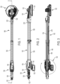
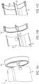
Figure 1 shows a top view of the pole sander; -
Figure 2 shows a side view of the pole sander; -
Figure 3 shows a vertical cross- sectional view of the pole sander; -
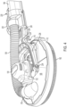
Figure 4 shows a perspective view of the sanding head; -
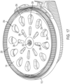
Figure 5 shows an underside view of the sanding head with the platen removed; -
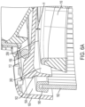
Figure 6A shows a vertical cross-sectional view of the edge of the sanding head; -
Figure 6B is the same asFigure 6A with the addition of hatching to show cross sectional area of gap between edge of the platen and the inner wall; -
Figure 7 shows a perspective view of the brush ring; -
Figure 8 shows a view of part of the top side of the plate with the leaf spring of thebrush ring 132 passing through an aperture from below the plate to attach to the top side of the plate; -
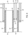
Figure 9 shows a schematic diagram showing how the two poles of the elongate body are telescopically connected to each other; -
Figure 10 shows the seals which connect between the two poles of the elongate body; -
Figure 11A shows the seal for thefirst pole 196 being attached to thefirst pole 196; -
Figure 11B shows a vertical cross section of the seal for thefirst pole 196 being attached to thefirst pole 196; -
Figure 11C shows the seal for thefirst pole 196 mounted on thefirst pole 196; -
Figure 12 shows the seals adjacent the ends of the aluminium tubes of the poles; -
Figure 13 shows a perspective cross section showing how the aluminium tubes and seals of the two poles of the elongate body are telescopically connected to each other; -
Figure 14 shows a perspective cross section showing how the aluminium tubes and seals of the two poles of the elongate body are telescopically connected to each other; -
Figure 15 shows a top view of the sanding head; -
Figure 16 shows a vertical cross section of the sanding head and lower end of thefirst pole 196; -
Figure 17 shows the underside view of the sanding head including the platen; -
Figure 18 shows the platen; -
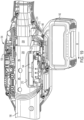
Figure 19 shows the rear housing with one of the clam shells removed; -
Figure 20 shows a vertical cross section of the rear housing; -
Figure 21 shows a top perspective view of the sanding head; -
Figure 22 shows the extension tube inside the handle section of the rear housing with the vacuum nozzle detached; -
Figure 23 shows the extension tube inside of the handle section of the rear housing with the vacuum nozzle attached; -
Figure 24 shows the rear end of the extension tube with the vacuum nozzle detached; -
Figure 25 shows the rear end of the extension tube with the vacuum nozzle attached; -
Figure 26A and Figure 26B show a first angle of where the tubular passageway of the hood engages with the arc shape aperture; -
Figure 27A and Figure 27B shows a second angle of where the tubular passageway engages with the arc shape aperture; -
Figure 28A and Figure 28B show a third angle of where the tubular passageway engages with the arc shape aperture; -
Figure 29A, Figure 29B andFigure 29c show a fourth angle of where the tubular passageway engages with the arc shape aperture; -
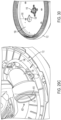
Figure 30 shows of an underside view of the sanding head with the platen removed which is an alternative design to that shown inFigure 5 ; and -
Figure 31 shows a side view of the sanding head. - Referring to
Figures 1 to 3 , the pole sander comprises a sandinghead 100 pivotally attached to one end of anelongate body 102 and arear housing 104 attached to the other end. - The
elongate body 102 is telescopic and is formed from twopoles - The sanding
head 100 connects to the end of theelongate body 102 via apivot mechanism 110 which is described in more detail below. The sandinghead 100 comprises ahood 112 on top of which is mounted anelectric motor 114. Themotor 114 is aDC brushless motor 114. Themotor 114 is enclosed by amotor housing 120 which is cup shaped and surrounds the top and sides of themotor 114. Themotor housing 120 attaches to the top of agear housing 122 which encloses a planetary gear set 124. Thegear housing 122 mounts on top of thehood 112. Themotor 114 is drivingly connected via the planetary gear set 124 to anoutput spindle 118 having alongitudinal axis 126 about which it rotates and which is located below thehood 112. Attached to the end ofoutput spindle 118 is acircular platen 116 which extends radially outwards from theoutput spindle 118. When themotor 114 is activated, themotor 114 rotationally drives theoutput spindle 118 and hence theplaten 116 about adrive axis 126. - A flexible
dust extraction pipe 128 attaches to the top of thehood 112 on one side of themotor 114. Anaperture 130 is formed through thehood 112. The end of theflexible pipe 128 surrounds theaperture 130. As such air can be drawn from beneathhood 112 through theaperture 130 and into theflexible pipe 128. This enables dust and debris generated during the operation of the pole sander to be removed from under thehood 112 by applying a suction force to theflexible pipe 128. The operation of the dust extraction of the pole sander is described in more detail below. - A
brush ring 132 attaches to the edge of thehood 112. Thebrush ring 132 is described in more detail below. - The
rear housing 104 is formed two plastic clam shells 134 which clamp to the end of theelongate body 102. Therear housing 104 comprises aforward mount section 136 andrear handle section 138. Abattery mount 140 is formed on the lower surface of the mount section of therear housing 104. Abattery pack 142 can be slid in a forward direction (Arrow M inFigure 19 ) onto thebattery mount 140 to attach it to therear housing 104 and in a rearward direction to detach it from thebattery mount 140. The design of thebattery mount 140 andbattery 142 are known in art and therefore will not be described in any more detail. -
Control electronics 144 for themotor 114 are mounted inside offorward mount 136 section of therear housing 104. Thecontrol electronics 144 are connected to themotor 114 via anelectric cable 146 which passes through asecond passageway 148 of theelongate body 102 through the length of theelongate body 102. Thecontrol electronics 144 control the operation of thebrushless motor 114. - A lock on/lock off
switch 150 is mounted on the top ofrear housing 104 where therear handle section 138 connects to theforward mount section 136. An operator can use the lock on/lock offswitch 150 to activate themotor 114. - An operator can support the pole sander by grasping the rear handle section138 of the
rear housing 104 in one hand and theelongate body 102 in the other. The operator can switch the pole sander on or off using the thumb of the hand grasping therear handle section 138. - A
vacuum connection nozzle 152 is mounted on the rear of therear housing 104 which connects to afirst passageway 154 which extends through the length of theelongate body 102. The other end of thesecond passage 154 connects to theflexible pipe 128. A vacuum cleaner (not shown) can be connected to thenozzle 152 and draw air from under thehood 112, through theflexible pipe 128, through thefirst passage 154 in theelongate body 102, through thenozzle 152 and into a vacuum cleaner. - The
hood 112 will now be described with reference toFigures 4 to 6 . - The
hood 112 comprises a flatcircular plate 156 which extends radially from a centralcircular hole 158 through which theoutput spindle 118 projects. Formed on the underside of theplate 156 around the edge is aperipheral wall 160 which projects perpendicularly to theplane 422 of thecircular plate 156. An inner circularinner wall 162 is formed on the underside of theplate 156 in close proximity to and concentrically with theperipheral wall 160. Theinner wall 162 has the same height as theperipheral wall 160 and extends in the same direction that is parallel to theperipheral wall 160. Acircular trough 164 is formed between the twowalls rectangular apertures 166 are formed through the base of thetrough 164. Theapertures 166 are located equidistantly around the centre of theplate 156 in a symmetrical fashion. Achamber 166 is formed between theinner wall 162 and the underside of theplate 156. - As shown in
Figure 5 , formed through theplate 156 between theinner wall 162 and the central hole is an arc shapedaperture 130 which allows air and debris to pass through theplate 156. Theaperture 130 has three edges, a firststraight edge 170 which extends tangentially to thelongitudinal axis 126 of theoutput spindle 118, asecond edge 172 of equal length which extends from the end of thefirst edge 170, perpendicularly to thefirst edge 170, in a direction away from thelongitudinal axis 126 of theoutput spindle 118, and a thirdcurved edge 174 extending between the ends of the first andsecond edges circular plate 156 has a radius R. The whole of the arc shapedaperture 130 is located at a distance of less than half of the radius fromlongitudinal axis 126 of theoutput spindle 118 or the centre of the plate 156 (<R/2). In alternative design as shown inFigure 30 , thecentre 418 of the arc shapedaperture 130 is located at a distance of less than half of the radius fromlongitudinal axis 126 of theoutput spindle 118 or the centre of the plate 156 (<R/2). - Integrally formed on the top side of the
plate 156 is acurved wall 178 which forms atubular passageway 176 from the arc shapedaperture 130 to anopening 420 where theflexible pipe 128 is attached. As shown inFigure 31 , anaxis 440 which passes perpendicularly through theplane 442 of theopening 420 of the tubular passageway is angled 430 at between 0 degrees and 10 degrees and ideally is at 5 degrees relative to theplane 422 of the plate. - Where the
tubular passageway 176 connects to the arc shapedaperture 130, it is shaped to engage with the arc shapedaperture 130 at certain angles to maximise the air flow efficiency. - Referring to
Figures 26A and 26B , the first angle of the exit of thetubular passageway 176 where it meets the arc shapedaperture 130 is is located in avertical plane 300 which passes through axis ofrotation 126 of theoutput spindle 118 across the end of thetubular passage 176 adjacent the arc shapedaperture 130. Theangle 302 in thisplane 300 between the axis ofrotation 126 of theoutput spindle 128 and the direction of thetubular passageway 176 is less than 90 degrees (perpendicular) but greater than 0 degrees (parallel) and is ideally between 20 degrees and 60 degrees. - Referring to
Figures 27A and 27B , the second angle of the exit of thetubular passageway 176 where it meets the arc shapedaperture 130 is is located in avertical plane 304 which extends tangentially to the axis ofrotation 126 of theoutput spindle 128, the part of theplane 304 which passes through the exit of thetubular passageway 176 being the closest part to the axis ofrotation 126 of theoutput spindle 118. Theangle 308 in thisplane 304 between the plane of thecircular plate 156 of thehood 112 and the direction of thetubular passage 176 in the turningdirection 306 of theplaten 116 is less than 90 degrees and is ideally between 20 degrees and 60 degrees. - Referring to
Figures 28A and 28B , the third angle of the exit of thetubular passageway 176 where it meets the arc shapedaperture 130 is located in avertical plane 402 which passes through two axes, an axis ofrotation 126 of theoutput spindle 118 andcentre axis 400 which is parallel to the axis ofrotation 126 of the output spindle but which passes through the centre of theaperture 130. Theangle 404 in thisplane 402 between the axis ofrotation 126 of theoutput spindle 118 and theaxis 400 through the centre of thetubular passageway 176 is less than 85 degrees but greater than 20 degrees. The third angle can be between 20 degrees and 60 degrees or between 20 degrees and 50 degrees or between 20 degrees and 40 degrees or between 30 degrees and 60 degrees or between 40 degrees and 60 degrees or between 30 degrees and 50 degrees. - Referring to
Figures 29 ,29B and29C , thefourth angle 308 of the exit of thetubular passageway 176 where it meets the arc shapedaperture 130 is located in avertical plane 414 which passes through two axes, acentre axis 400, which is parallel to the axis ofrotation 126 of the output spindle but which passes through the centre of theaperture 130 and asecond axis 410, which is parallel to the centre axis and which passes through the part of theopening 420 of the tubular passageway located furthest from the axis of rotation of the output spindle. Theangle 412 in thisplane 414 between theplane 422 of thecircular plate 156 of thehood 112 and the direction of thetubular passage 176 in the turningdirection 306 of aplaten 116 when mounted on the output spindle is between 15 degrees and 50 degrees. The fourth angle can be between 20 degrees and 50 degrees or between 20 degrees and 40 degrees or between 30 degrees and 50 degrees or between 40 degrees and 60 degrees or between 30 degrees and 50 degrees. - The
hood 112 is formed in a one-piece construction from plastic. - The
brush ring 132 will now be described with reference to 6 to 8. - The
brush ring 132 comprises a plasticcircular ring 180 which is sized so that it is capable of locating inside of thetrough 164. Extending perpendicularly from the bottom side of thering 180 are a series ofbristles 182. Attached to the opposite top side of thebrush ring 132 are theends 184 of sixleaf springs 186. The leaf springs 186 are formed from sheet metal and are resiliently deformable in a direction perpendicular to the plane of the sheet. The leaf springs 186 comprises acentral section 188 located between twoend sections end sections ring 180. Thecentral section 188 of theleaf springs 186 extends upwardly at a slight angle to the plane of thecircular ring 180. Eachcentral section 188 of eachleaf spring 186 extends through therectangular aperture 166 in thetrough 164 and attaches to thetop side 194 of theplate 156 as shown inFigure 8 . The leaf springs 186 bias thering 180 to a position where it is located at a distance from the base of thetrough 164 as shown inFigure 6 . In this position, thebristles 182 project below thehood 112. When the sandinghead 100 is placed against a work surface, thebristles 182 engage with the work surface. When the sandinghead 100 is pushed against the work surface, thebrush ring 132 is pushed into thetrough 164 against the biasing force of the leaf springs 186. The leaf springs 186 ensure that thebristles 182 are biased into engagement with the work surface. When the sandinghead 100 is removed from the surface, thebrush ring 132 returns to its original position due to the resilient nature of the leaf springs 186. - A
plastic cover 195 is located over the topside of thehood 112 enclosing theends 190 of theleaf springs 186 attached to thetop side 194. - The telescopic
elongate body 102 will now be described with reference toFigures 1 to 3 and 9 to 14. - The pole sander has an
elongate body 102 comprising afirst pole 196 which is capable of sliding in and out of asecond pole 198 in a telescopic manner to enable the length of the pole sander to be adjusted. A locking mechanism 200 is used to lock thefirst pole 196 to thesecond pole 198 when the twopoles - Inside both of the
poles passageways poles larger passageway 154 is used to transport air (due to suction) and entrained dust and debris, generated during the use of the pole sander, through thepoles vacuum nozzle 152 at the opposite end, thenozzle 152 being connected to a vacuum cleaner. The secondsmaller passageway 148 is used as a conduit forelectric cable 146 which provide power and control signals from acontrol electronics 144 for theelectric motor 114 mounted in the sandinghead 100. - The
first pole 196 comprises a single aluminium tube with aninternal wall 202 located inside of the tube, which runs the length of the tube to form the twopassageways first pole 196. The firstlarger passageway 154 forms part of the first passageway which is used to transport air. The secondsmaller passageway 148 forms part of the passageway which is used as a conduit for theelectric cable 146. Afirst seal 204 attaches to the end of thefirst pole 196 which is inserted into thesecond pole 198. The shape of theseal 204 corresponds to that of the end of the aluminium tube andinternal wall 202. Thefirst seal 204 provides a seal between thefirst pole 196 and thesecond pole 198. It also acts as a slide bearing. - The
second pole 198 comprises twoaluminium tubes second aluminium tube 208 locates inside of thefirst aluminium tube 206 and runs the full length of thefirst tube 206, their longitudinal axes being parallel to each other. Thesecond aluminium tube 208 forms part of the first passageway which is used to transport air and dust or debris. Thefirst aluminium tube 206 forms part of thepassageway 154 which is used as a conduit. Asecond seal 210 is attached to the end of thefirst aluminium tube 206 into which thefirst pole 196 is inserted. The shape of thesecond seal 210 corresponds to that of the end of thealuminium tube 206. Athird seal 212 is attached to the end of thesecond aluminium tube 208 which is inserted into thesecond passage 148 way of thefirst pole 196. The shape of thethird seal 212 corresponds to that of the end of thesecond aluminium tube 208. Theseals first pole 196 and thesecond pole 198. They also act as slide bearings. The twotubes seals tubes - The
poles third seal 212 of thesecond aluminium tube 208 of thesecond pole 198 is inserted into thesecond passageway 148 of thefirst pole 196 through theseal 212. The end of thefirst pole 196 with thefirst seal 204, with thesecond aluminium tube 208 inside of it, is then inserted into the end of thefirst aluminium tube 206 of thesecond pole 198 with thesecond seal 212. - The
larger passageway 154 in thefirst pole 196 connects directly to an end of the flexible tube via a collar 214. Thelarger passageway 154 in thesecond pole 198 connects to an end of thevacuum attachment nozzle 152 via an extension tube 216. - As the
poles electronic control electronics 144 in therear housing 104. in order to ensure that the whole ofelongate body 102 is grounded, ideally, theseals poles - In addition or as an alternative,
metal contacts 218 such as leaf springs can be located between thetelescopic poles poles - The
pivot mechanism 110 will not be described with reference toFigures 4 ,15 and16 . - Attached to the end of the
first pole 196 in a fixed manner is an end housing 220 (seeFigures 1 and 2 ) comprising twoclam shells 222 attached to each other using screws (only one clam shell is shown inFigure 4 ). Thepivot mechanism 110 connects the sandinghead 100 to thefirst pole 196 via theend housing 220. - The
pivot mechanism 110 comprises afork 224 having twoarms 226, acentral interconnecting section 228 and apole support section 230. The twoarms 226 extend in parallel in a forward direction from the ends of thecentral interconnecting section 228 in a symmetrical manner. Thepole support section 230 connects to the centre of theinterconnection section 228 on the opposite side of the twoarms 226 and projects in a rearward direction opposite but parallel to that of the twoarms 226. - Formed in each side of the
gear housing 122 in a symmetrical manner are threaded apertures. Theaxis 232 of the of the apertures are aligned with each other and are horizontal. Formed in the ends of the twoarms 226 are apertures. When thefork 224 is attached to the sandinghead 100, the ends of the twoarms 226 align with the apertures formed in the gear housing. Abolt 234 is passed through each aperture in the end of the eacharm 226 and screw into the threaded aperture in the side of thegear housing 122 to attach thefork 224 in a pivotal manner. Thefork 224 can pivot around thebolts 234 about a horizontalsideways axis 232. - Rigidly mounted in a recess formed in the end of the
pole support section 228 is the rear half of anaxle 234. Theaxle 234 projects rearwardly. Formed in theend housing 220 is anelongate recess 236. Therecess 236 extends in a direction parallel to the longitudinal axis of thefirst pole 196. The forward half of theaxle 234 is mounted inside of therecess 236 via twobearings 240 supported by the end housing in the side walls of the recess. Thebearings 240 allow the axle to rotate within the recess. The axle can rotate about an axis which is parallel to the longitudinal axis of thefirst pole 196 and which passes through the length of the secondsmaller passage 148 of theelongate body 102. This allows thefork 224, together with sandinghead 100, to pivot about an axis which is parallel to the longitudinal axis of thefirst pole 196 and which passes through the length of the secondsmaller passage 148 of theelongate body 102. The axis also crosses theoutput axis 126 of the drive spindle. - The sanding
head 100 has a centre ofgravity 242. As best seen inFigure 15 , the axis ofpivot 232 of thefork 224 on the sandinghead 100 is located forward (distance D inFigure 15 ) of the centre ofgravity 242. Furthermore, the axis ofpivot 232 of thefork 224 on the sandinghead 100 100 is located forward of thedrive axis 126 of theoutput spindle 118. This allows the sandinghead 100, which can freely rotate about thebolts 234, to automatically pivot to an angular position where it is parallel to a wall when the sandinghead 100 is raised by an operator. - When the plane of the
platen 116 is parallel to the longitudinal axis of theelongate body 102 as shown inFigure 16 , the axis of rotation of the axle is located below the centre ofgravity 242 of the of the sandinghead 100. - The design of the
platen 116 will now be described with reference toFigures 17 and18 . - The
platen 116 comprises aplastic disc 244 with ametal insert 246 located at the centre. Attached to the bottom of disk is layer made of asoft foam 248. Attached on the opposite side of the soft foam layer is a sheet ofVelcro 250. TheVelcro 250 is used to attach the sandpaper to theplaten 116. - The
platen 116 is attached to theoutput spindle 118 using abolt 252. Theplaten 116 is circular and extends radially from thedrive axis 126 in a direction perpendicular to thedrive axis 126. Two sets ofair holes platen 116 to allow air and debris to pass through theplaten 116. Thefirst set 254 are located towards the outer edge of the platen and in a symmetrical manner around theaxis 126. Theholes 254 of the first set are tear shaped with the narrower end pointing towards the centre. The straight sides of theholes 254 align with the centre of theplaten 116. The second set ofhole 256 are located between thefirst set 254 and the centre of theplaten 116 in a symmetrical manner. Theholes 256 of the second set are smaller than those of the first set. Theholes 256 of the second set are tear shaped with the narrower end pointing towards the centre. The straight sides of theholes 256 align with the centre of theplate 116. - Referring to
Figure 6A , aspace 258 is formed between the top of theplaten 116 and the underside of thehood 112. In the present design, the size H of the space is kept to a minimum. This ensures that the air speed above theplaten 116 is kept as high as possible. If the air speed slows, entrained dust and debris will deposit on the surface of the underside of thehood 112 and therefore will build up. By keeping the air speed high, the dust remains entrained and therefore can be drawn out theflexible pipe 128 due to the suction from a vacuum cleaner. The air flow around therotating platen 116 is improved due to the inner circularinner wall 162 which is adjacent the outer edge of theplaten 116. Theinner wall 162 locates between the edge of the paten and thebristles 182 of thebrush ring 132. Theinner wall 162 guides the moving air in a smooth manner and minimises the amount of contact between the moving air and thebristles 182 of thebrush ring 132. If the moving air were to come into contact with thebristles 182, the air flow would become non-uniform as its passes through thebristles 182. Furthermore, the use of theinner wall 162 to separate thebristles 182 from the edge of theplaten 116 minimises the amount of dust and debris that collects within thebristles 182. - The cross-sectional area of the
gap 260 between theinner wall 162 and the edge of the platen 116 (shown by thehatchings 262 inFigure 6B ) is the same as that of the cross-sectional area of theflexible pipe 128 which in turn is the same as that of thefirst passageway 154 way in the twopoles - Referring to
Figure 19 , thesecond pole 198 extends into themount section 136 of therear housing 104. Apart 270 of the side wallfirst aluminium tube 206 of thesecond pole 198 has been removed to expose the surface of thesecond aluminium tube 208. Thecontrol electronics 144 are mounted in a control module. Where thepart 270 of the first aluminium tube has been removed, thecontrol module 144 is mounted inside of thefirst aluminium tube 206 adjacent thesecond aluminium tube 208. This enables heat generated by theelectronic module 144 to be transferred to thesecond aluminium tube 208 which is a good heat conductor and transfer the heat away from thecontrol module 144. Furthermore, during the operation of the pole sander, air is drawn through thesecond aluminium tube 208 by a vacuum cleaner. The air flow acts to cool thesecond aluminium tube 208 which in turn acts to cool theelectronic module 144. - The
control electronics 144 are connected directly to themotor 114 using a singleelectrical cable 146 which carries the wires use to provide the electrical current to the windings of thebrushless motor 114. One end of thecable 146 connects directly to thecontrol electronics 144 via asoldering tag 272 which connects toelectric interface 274. The other end connects directly to themotor 114. Thecable 146 is continuous with no plugs or connectors being used so as avoid interfering with the signals generated by thecontrol electronics 144 which are sent down thecable 146 to operate themotor 114. Acentral section 276 of thecable 146 located inside of the twopoles cable 146 in a direction parallel to the longitudinal axis of thepoles poles cable 146 exit thefirst pole 196 and pass across thepivot mechanism 110, it locates against the side offlexible pipe 128 as shown inFigure 21 . In order to maintain the position of thecable 146 relative to theflexible pipe 128, atubular sheaf 278 surrounds both thecable 146 and theflexible pipe 128 as shown inFigures 26 and27 . - An
extension tube 280 connects to the end of thesecond aluminium tube 208 of thesecond pole 198 which extends thefirst passageway 154 of thesecond pole 198 through therear handle section 138 of therear housing 104 and projects rearwardly of thehandle section 138. Avacuum nozzle 152 is releasably attachable to the end of theextension tube 280 via a clip 282. The clip 282 comprises a first part formed on thevacuum nozzle 152 and a second part formed on the end of theextension tube 280. The first part comprises twopins 284, eachpin 284 being mounted on the end of a resilientlydeformable leg 286. The second part comprise twoholes 288 formed through the side wall of the end of theextension tube 280 in corresponding locations to thepins 284. To attach thevacuum nozzle 152, thelegs 286 are bent inwardly so that thepins 284 can slide inside of the end of theextension tube 280 as thevacuum nozzle 152 is slid into theextension tube 280. When thepins 284 align with theholes 288, thepins 284 are biased into theholes 288 by theresilient legs 286 bending back to their original position. Whilst thepins 284 are located in theholes 288, thevacuum nozzle 152 remains attached to theextension tube 280. To detach thevacuum nozzle 152 thepins 284 are pushed back into the apertures to disengage them from theholes 288. Thenozzle 152 is slid out of theextension tube 280. Thevacuum nozzle 152 can be attached to the hose of a vacuum cleaner. As thenozzle 152 can be easily attached and detached, a suitable design ofnozzle 152 can be chosen depending on the type of vacuum cleaner utilised. Furthermore, if thenozzle 152 breaks it can be easily replaced.
Claims (12)
- A handheld pole sander for performing different surface machining treatments including but not limited to sanding, polishing, grinding or rubbing a work surface comprising:an elongate body (102) having two ends;a sanding head (100) attached via a pivot mechanism (110) to a first end of the elongate body (102);an electric motor (114) mounted on the sander;wherein the sanding head (100) comprises:a hood (112) comprising a circular plate (156) and a sidewall (162) to form a chamber (166); an output spindle (118) which projects from the hood (112) into the chamber (166); anda wall (178) mounted on top of the plate which forms a tubular passageway from an aperture (130) formed through the plate (130) to an opening;wherein the electric motor (114), when activated, rotatingly drives the output spindle (118);wherein the elongate body comprises a first passageway (154) which extends through the length of the elongate body and which is used to transport air through the length of the elongate body (102);wherein a flexible pipe (128) connects between a first end of the first passageway at the first end of the elongate body (102) and the opening to connect the chamber (166) to the first passageway;characterised in that the centre (418) of the aperture is located at a distance of less than half of the radius of the circular plate from longitudinal axis (126) of the output spindle (118) or the centre of the plate (156) (<R/2).
- A handheld pole sander for performing different surface machining treatments including but not limited to sanding, polishing, grinding or rubbing a work surface comprising:an elongate body (102) having two ends;a sanding head (100) attached via a pivot mechanism (110) to a first end of the elongate body (102);an electric motor (114) mounted on the sander;wherein the sanding head (100) comprises:a hood (112) comprising a plate (156) and a sidewall (162) to form a chamber (166);an output spindle (118) which projects from the hood (112) into the chamber (166); anda wall (178) mounted on top of the plate which forms a tubular passageway from an aperture (130) formed through the plate (130) to an opening;wherein the electric motor (114), when activated, rotatingly drives the output spindle (118);wherein the elongate body comprises a first passageway (154) which extends through the length of the elongate body and which is used to transport air through the length of the elongate body (102);wherein a flexible pipe (128) connects between a first end of the first passageway at the first end of the elongate body (102) and the opening to connect the chamber (166) to the first passageway;characterised in that the exit of the tubular passageway has a first angle located in a vertical plane (300) which passes through an axis of rotation (126) of the output spindle (118) across the end of the tubular passage (176) adjacent the aperture (130);wherein the angle (302) in this plane (300) between the axis of rotation (126) of the output spindle (128) and the direction of the tubular passageway (176) is less than 90 degrees (perpendicular) but greater than 0 degrees (parallel) and ideally less than 85 degrees but greater than 20 degrees.
- A handheld pole sander as claimed in claim 2 wherein the first angle is between 20 degrees and 60 degrees or between 20 degrees and 50 degrees or between 20 degrees and 40 degrees or between 30 degrees and 60 degrees or between 40 degrees and 60 degrees or between 30 degrees and 50 degrees.
- A handheld pole sander as claimed in either of claims 2 or 3 wherein the exit of the tubular passage has a second angle located in a vertical plane (304) which extends tangentially to the axis of rotation (126) of the output spindle (128), the part of the plane (304) which passes through the exit of the tubular passageway (176) being the closest part to the axis of rotation 126 of the output spindle (118);
wherein the angle 308 in this plane (304) is between the plane of the circular plate (156) of the hood (112) and the direction of the tubular passage (176) in the turning direction (306) of the platen (116) is less than 90 degrees and is ideally either between 20 degrees and 60 degrees or between 15 and 50 degrees or between 15 degrees and 60 degrees or between 20 degrees and 50 degrees. - A handheld pole sander for performing different surface machining treatments including but not limited to sanding, polishing, grinding or rubbing a work surface comprising:an elongate body (102) having two ends;a sanding head (100) attached via a pivot mechanism (110) to a first end of the elongate body (102);an electric motor (114) mounted on the sander;wherein the sanding head (100) comprises:a hood (112) comprising a plate (156) and a sidewall (162) to form a chamber (166);an output spindle (118) which projects from the hood (112) into the chamber (166); anda wall (178) mounted on top of the plate which forms a tubular passageway from an aperture (130) formed through the plate (130) to an opening;wherein the electric motor (114), when activated, rotatingly drives the output spindle (118);wherein the elongate body comprises a first passageway (154) which extends through the length of the elongate body and which is used to transport air through the length of the elongate body (102);wherein a flexible pipe (128) connects between a first end of the first passageway at the first end of the elongate body (102) and the opening to connect the chamber (166) to the first passageway;characterised in that the exit of the tubular passage has a fourth angle located in a vertical plane (414) which extends tangentially to the axis of rotation (126) of the output spindle (128), the part of the plane (304) which passes through the exit of the tubular passageway (176) being the closest part to the axis of rotation (126) of the output spindle (118);wherein the angle 308 in this plane (304) between the plane of the circular plate (156) of the hood (112) and the direction of the tubular passage (176) in the turning direction (306) of the platen (116) is less than 90 degrees and is ideally either between 20 degrees and 60 degrees or between 15 and 50 degrees or between 15 degrees and 60 degrees or between 20 degrees and 50 degrees.
- A handheld pole sander as claimed in either of claims 4 or 5 wherein the second angle is between 20 degrees and 60 degrees or between 20 degrees and 50 degrees or between 20 degrees and 40 degrees or between 30 degrees and 60 degrees or between 40 degrees and 60 degrees or between 30 degrees and 50 degrees.
- A handheld pole sander as claimed in any of the previous claims wherein the plate (156) is circular;
wherein the whole of the aperture is located at a distance of less than half of the radius of the circular plate from longitudinal axis (126) of the output spindle 118 or the centre of the plate (156) (<R/2). - A handheld pole sander for performing different surface machining treatments including but not limited to sanding, polishing, grinding or rubbing a work surface comprising:an elongate body (102) having two ends;a sanding head (100) attached via a pivot mechanism (110) to a first end of the elongate body (102);an electric motor (114) mounted on the sander;wherein the sanding head (100) comprises:a hood (112) comprising a circular plate (156) and a sidewall (162) to form a chamber (166);an output spindle (118) which projects from the hood (112) into the chamber (166); anda wall (178) mounted on top of the plate which forms a tubular passageway from an aperture (130) formed through the plate (130) to an opening;wherein the electric motor (114), when activated, rotatingly drives the output spindle (118);wherein the elongate body comprises a first passageway (154) which extends through the length of the elongate body and which is used to transport air through the length of the elongate body (102);wherein a flexible pipe (128) connects between a first end of the first passageway at the first end of the elongate body (102) and the opening to connect the chamber (166) to the first passageway;characterised in that the whole of the aperture is located at a distance of less than half of the radius of the circular plate from longitudinal axis (126) of the output spindle (118) or the centre of the plate (156) (<R/2).
- A handheld pole sander as claimed in any of the previous claims wherein the aperture is an arc shaped aperture (130).
- A handheld pole sander as claimed in claim 9 wherein the aperture (130) has three edges, a first straight edge (170) which extends tangentially to the longitudinal axis (126) of the output spindle (118), a second edge (172) of equal length which extends from the end of the first edge.
- A handheld pole sander as claimed in claim 9 wherein the aperture (130) has three edges, a first straight edge (170) which extends tangentially to the longitudinal axis (126) of the output spindle (118), a second edge (172) of equal length which extends from the end of the first edge (170), perpendicularly to the first edge (170), in a direction away from the longitudinal axis (126) of the output spindle (118), and a third curved edge (174) extending between the ends of the first and second edges (170, 172).
- A handheld pole sander as claimed in any of the previous claims wherein an axis (440) which passes perpendicularly through the plane (442) of the opening (420) of the tubular passageway is angled (430) at between 0 degrees and 10 degrees and ideally is at 5 degrees relative to the plane (422) of the plate.
Applications Claiming Priority (4)
| Application Number | Priority Date | Filing Date | Title |
|---|---|---|---|
| GB201915324A GB201915324D0 (en) | 2019-10-23 | 2019-10-23 | Pole sander |
| GB1919409.1A GB2590708A (en) | 2019-12-23 | 2019-12-23 | Pole sander |
| EP22166274.5A EP4063068A1 (en) | 2019-10-23 | 2020-10-05 | Pole sander |
| EP20200127.7A EP3838480A3 (en) | 2019-10-23 | 2020-10-05 | Pole sander |
Related Parent Applications (2)
| Application Number | Title | Priority Date | Filing Date |
|---|---|---|---|
| EP22166274.5A Division EP4063068A1 (en) | 2019-10-23 | 2020-10-05 | Pole sander |
| EP20200127.7A Division EP3838480A3 (en) | 2019-10-23 | 2020-10-05 | Pole sander |
Publications (1)
| Publication Number | Publication Date |
|---|---|
| EP4289552A1 true EP4289552A1 (en) | 2023-12-13 |
Family
ID=72752370
Family Applications (3)
| Application Number | Title | Priority Date | Filing Date |
|---|---|---|---|
| EP23181651.3A Pending EP4289552A1 (en) | 2019-10-23 | 2020-10-05 | Pole sander |
| EP22166274.5A Pending EP4063068A1 (en) | 2019-10-23 | 2020-10-05 | Pole sander |
| EP20200127.7A Pending EP3838480A3 (en) | 2019-10-23 | 2020-10-05 | Pole sander |
Family Applications After (2)
| Application Number | Title | Priority Date | Filing Date |
|---|---|---|---|
| EP22166274.5A Pending EP4063068A1 (en) | 2019-10-23 | 2020-10-05 | Pole sander |
| EP20200127.7A Pending EP3838480A3 (en) | 2019-10-23 | 2020-10-05 | Pole sander |
Country Status (2)
| Country | Link |
|---|---|
| US (1) | US11919127B2 (en) |
| EP (3) | EP4289552A1 (en) |
Citations (9)
| Publication number | Priority date | Publication date | Assignee | Title |
|---|---|---|---|---|
| EP0727281A1 (en) | 1995-02-16 | 1996-08-21 | Porter-Cable Corporation | Motorized sander |
| EP2033738A2 (en) | 2005-05-02 | 2009-03-11 | Flex-Elektrowerkzeuge GmbH | Portable sander and tool holder device |
| US7625264B1 (en) * | 2008-09-23 | 2009-12-01 | Jeff Gordon | Pneumatic dry wall sander |
| WO2014086873A1 (en) | 2012-12-07 | 2014-06-12 | Flex-Elektrowerkzeuge Gmbh | Handheld grinder |
| DE102014103019A1 (en) | 2014-03-06 | 2015-09-10 | Flex-Elektrowerkzeuge Gmbh | Tool head for a hand-held grinder and hand-held grinder |
| DE102014112355A1 (en) | 2014-08-28 | 2016-03-03 | Flex-Elektrowerkzeuge Gmbh | Tool head and hand-held machine tool |
| EP3083139A1 (en) | 2013-12-19 | 2016-10-26 | Flex-Elektrowerkzeuge GmbH | Hand-held grinder |
| EP3132892A2 (en) * | 2015-08-20 | 2017-02-22 | Techtronic Power Tools Technology Limited | Multi-sander kit |
| US20190232456A1 (en) * | 2018-02-01 | 2019-08-01 | Makita Corporation | Long rod polishing device |
Family Cites Families (43)
| Publication number | Priority date | Publication date | Assignee | Title |
|---|---|---|---|---|
| US3793781A (en) * | 1972-03-10 | 1974-02-26 | A Hutchins | Reciprocating abrading or polishing tool |
| US4329078A (en) | 1980-03-03 | 1982-05-11 | Jameson Corporation | Splice joint lock |
| US4685252A (en) | 1985-07-22 | 1987-08-11 | Ponce Felix C | Reciprocating sander |
| US4782632A (en) * | 1987-10-01 | 1988-11-08 | William Matechuk | Drywall sander |
| US5125190A (en) * | 1990-05-16 | 1992-06-30 | Buser John P | Dust collector and shield for rotary grinder |
| GB9020317D0 (en) | 1990-09-18 | 1990-10-31 | Cross Mfg Co | Sealing devices |
| US5239783A (en) | 1991-08-20 | 1993-08-31 | William Matechuk | Drywall sander |
| DE9216257U1 (en) | 1992-11-30 | 1994-03-31 | Siemens Ag | Suction pipe for a vacuum cleaner |
| CA2152522A1 (en) | 1994-07-01 | 1996-01-02 | William R. Witkowski | Connection for two-part handle |
| US5511269A (en) | 1994-12-05 | 1996-04-30 | Watson; Kay F. | Battery powered tile cleaning apparatus |
| US6855040B2 (en) * | 1997-01-23 | 2005-02-15 | Hao Chien Chao | Ergonomically friendly orbital sander construction |
| US6979254B1 (en) * | 1997-01-23 | 2005-12-27 | Hao Chien Chao | Ergonomically friendly orbital sander construction |
| US6004197A (en) * | 1997-01-23 | 1999-12-21 | Hao Chien Chao | Ergonomically friendly random orbital sander construction |
| DE60030585T2 (en) | 1999-12-21 | 2007-09-13 | Kao Corp. | STRUCTURE OF PIPE CONNECTION AND CLEANING DEVICE |
| JP4067257B2 (en) | 1999-12-21 | 2008-03-26 | 花王株式会社 | Pipe connection structure |
| US6468141B1 (en) | 2000-11-22 | 2002-10-22 | John S. Conboy | Drywall sander |
| US6546596B2 (en) | 2001-01-08 | 2003-04-15 | Rick V. Grote | Extension pole for tools |
| US6758731B2 (en) * | 2001-08-10 | 2004-07-06 | One World Technologies Limited | Orbital sander |
| SE525720C2 (en) | 2003-11-14 | 2005-04-12 | Aba Sweden Ab | Arrangement is for coupling together two rigid tubular objects and comprises male part and female part |
| US7220174B2 (en) | 2004-09-29 | 2007-05-22 | Black & Decker Inc. | Drywall sander |
| DE202005008613U1 (en) | 2005-06-02 | 2005-08-25 | Ho Cheng Garden Tools Co., Ltd., Fu Shing | Telescopic tube, e.g. for gardening tool, has positioning element movably mounted in accommodation chamber extending through sleeve and outer tube for reversible locking in positioning holes, control element with ends in adjustment slots |
| WO2008033377A2 (en) | 2006-09-12 | 2008-03-20 | Black & Decker Inc. | Sanding tool with pivotally coupled head assembly |
| US8137165B2 (en) * | 2008-01-15 | 2012-03-20 | Dust Collection Products, Llc | Dust shroud with adjustable mounting mechanism |
| US8133094B2 (en) * | 2008-01-21 | 2012-03-13 | Dust Collection Products, Llc | Dust shroud with access hatch retention mechanism |
| DE102008055797A1 (en) | 2008-11-04 | 2010-05-06 | Kai Roscher | grinding machine |
| DE102008064564A1 (en) | 2008-12-23 | 2010-06-24 | Flex-Elektrowerkzeuge Gmbh | Tool holding head for a hand-held cleaning / grinding machine and hand-held cleaning / grinding machine |
| US8702478B2 (en) * | 2009-05-08 | 2014-04-22 | Michael Loveless | Angle grinder dust shroud with unitary adjustable mounting collar |
| DE102009021595B4 (en) | 2009-05-15 | 2011-04-28 | Fischer Rohrtechnik Gmbh | Plug-in pipe system for a vacuum cleaner |
| JP5323624B2 (en) | 2009-09-14 | 2013-10-23 | 株式会社マキタ | Dust collector cover for disc grinder |
| US8801506B2 (en) * | 2011-11-28 | 2014-08-12 | X'pole Precision Tools Inc. | Dust collection hood for grinding machine tools |
| JP5734233B2 (en) | 2012-03-30 | 2015-06-17 | 日立アプライアンス株式会社 | Electric vacuum cleaner |
| US9120217B2 (en) | 2013-02-07 | 2015-09-01 | Suncast Technologies, Llc | Snow rake with telescoping pole |
| DE102013213271A1 (en) | 2013-07-05 | 2015-01-08 | Flex-Elektrowerkzeuge Gmbh | Hand held grinding machine |
| DE102014113881A1 (en) | 2014-09-25 | 2016-03-31 | Metabowerke Gmbh | Machine tool and support structure for this |
| US10272558B2 (en) | 2015-10-14 | 2019-04-30 | Black & Decker Inc. | Power tool having an elongated housing supporting a power module |
| EP3208040A1 (en) | 2016-02-17 | 2017-08-23 | HILTI Aktiengesellschaft | Angle grinder dust hood |
| DE102016106557A1 (en) | 2016-04-11 | 2017-10-12 | Festool Gmbh | Hand machine tool with a drive motor |
| DE102016106556A1 (en) | 2016-04-11 | 2017-10-12 | Festool Gmbh | Hand machine tool with a suction hose |
| DE102016106558A1 (en) | 2016-04-11 | 2017-10-12 | Festool Gmbh | Hand machine tool with a circuit breaker |
| CN109227254A (en) | 2017-07-10 | 2019-01-18 | 浙江博来工具有限公司 | A kind of sander |
| US10933506B2 (en) * | 2018-02-12 | 2021-03-02 | The Boeing Company | Monopodic sander and method for operating the same |
| CN209304229U (en) | 2019-01-07 | 2019-08-27 | 杭州宸芯电子商务有限公司 | Wall surface grinding machine dust suction radiator |
| TWM584376U (en) | 2019-05-31 | 2019-10-01 | 周清耀 | Telescopic pipe fitting capable of adjusting and memorizing length |
-
2020
- 2020-10-05 EP EP23181651.3A patent/EP4289552A1/en active Pending
- 2020-10-05 EP EP22166274.5A patent/EP4063068A1/en active Pending
- 2020-10-05 EP EP20200127.7A patent/EP3838480A3/en active Pending
- 2020-10-21 US US17/075,803 patent/US11919127B2/en active Active
Patent Citations (9)
| Publication number | Priority date | Publication date | Assignee | Title |
|---|---|---|---|---|
| EP0727281A1 (en) | 1995-02-16 | 1996-08-21 | Porter-Cable Corporation | Motorized sander |
| EP2033738A2 (en) | 2005-05-02 | 2009-03-11 | Flex-Elektrowerkzeuge GmbH | Portable sander and tool holder device |
| US7625264B1 (en) * | 2008-09-23 | 2009-12-01 | Jeff Gordon | Pneumatic dry wall sander |
| WO2014086873A1 (en) | 2012-12-07 | 2014-06-12 | Flex-Elektrowerkzeuge Gmbh | Handheld grinder |
| EP3083139A1 (en) | 2013-12-19 | 2016-10-26 | Flex-Elektrowerkzeuge GmbH | Hand-held grinder |
| DE102014103019A1 (en) | 2014-03-06 | 2015-09-10 | Flex-Elektrowerkzeuge Gmbh | Tool head for a hand-held grinder and hand-held grinder |
| DE102014112355A1 (en) | 2014-08-28 | 2016-03-03 | Flex-Elektrowerkzeuge Gmbh | Tool head and hand-held machine tool |
| EP3132892A2 (en) * | 2015-08-20 | 2017-02-22 | Techtronic Power Tools Technology Limited | Multi-sander kit |
| US20190232456A1 (en) * | 2018-02-01 | 2019-08-01 | Makita Corporation | Long rod polishing device |
Also Published As
| Publication number | Publication date |
|---|---|
| EP4063068A1 (en) | 2022-09-28 |
| US11919127B2 (en) | 2024-03-05 |
| EP3838480A3 (en) | 2021-07-14 |
| EP3838480A2 (en) | 2021-06-23 |
| US20210121999A1 (en) | 2021-04-29 |
Similar Documents
| Publication | Publication Date | Title |
|---|---|---|
| EP3812090A2 (en) | Pole sander | |
| EP3858543B1 (en) | Pole sander | |
| EP3646768B1 (en) | Vacuum cleaner | |
| CN108527092B (en) | Sanding machine capable of being operated by two hands | |
| EP3812091B1 (en) | Pole sander | |
| EP3812093A1 (en) | Pole sander | |
| GB2590706A (en) | Pole sander | |
| GB2590685A (en) | Pole sander | |
| GB2590707A (en) | Pole sander | |
| EP4289552A1 (en) | Pole sander | |
| EP3812092A2 (en) | Pole sander | |
| EP3812089A1 (en) | Pole sander | |
| GB2590708A (en) | Pole sander | |
| GB2590687A (en) | Pole sander | |
| GB2590683A (en) | Pole sander | |
| GB2590686A (en) | Pole sander | |
| GB2590709A (en) | Pole sander | |
| GB2590684A (en) | Pole sander | |
| GB2590705A (en) | Pole sander | |
| GB2590704A (en) | Pole sander | |
| GB2590682A (en) | Pole sander | |
| CN110644402B (en) | Blowing and sucking machine | |
| GB2592572A (en) | Pole Sander | |
| US11867224B2 (en) | Locking mechanism for two telescoping poles of a power tool | |
| CN220637373U (en) | Multifunctional polishing machine for metal processing |
Legal Events
| Date | Code | Title | Description |
|---|---|---|---|
| PUAI | Public reference made under article 153(3) epc to a published international application that has entered the european phase |
Free format text: ORIGINAL CODE: 0009012 |
|
| STAA | Information on the status of an ep patent application or granted ep patent |
Free format text: STATUS: THE APPLICATION HAS BEEN PUBLISHED |
|
| AC | Divisional application: reference to earlier application |
Ref document number: 3838480 Country of ref document: EP Kind code of ref document: P Ref document number: 4063068 Country of ref document: EP Kind code of ref document: P |
|
| AK | Designated contracting states |
Kind code of ref document: A1 Designated state(s): AL AT BE BG CH CY CZ DE DK EE ES FI FR GB GR HR HU IE IS IT LI LT LU LV MC MK MT NL NO PL PT RO RS SE SI SK SM TR |
|
| STAA | Information on the status of an ep patent application or granted ep patent |
Free format text: STATUS: REQUEST FOR EXAMINATION WAS MADE |
|
| 17P | Request for examination filed |
Effective date: 20231223 |
|
| RBV | Designated contracting states (corrected) |
Designated state(s): AL AT BE BG CH CY CZ DE DK EE ES FI FR GB GR HR HU IE IS IT LI LT LU LV MC MK MT NL NO PL PT RO RS SE SI SK SM TR |