EP4289538A2 - Rotary cutting tool having disk-shaped cutting body and indexable cutting insert therefor - Google Patents
Rotary cutting tool having disk-shaped cutting body and indexable cutting insert therefor Download PDFInfo
- Publication number
- EP4289538A2 EP4289538A2 EP23193269.0A EP23193269A EP4289538A2 EP 4289538 A2 EP4289538 A2 EP 4289538A2 EP 23193269 A EP23193269 A EP 23193269A EP 4289538 A2 EP4289538 A2 EP 4289538A2
- Authority
- EP
- European Patent Office
- Prior art keywords
- insert
- cutting
- cutting insert
- imaginary
- define
- Prior art date
- Legal status (The legal status is an assumption and is not a legal conclusion. Google has not performed a legal analysis and makes no representation as to the accuracy of the status listed.)
- Granted
Links
Images




Classifications
-
- B—PERFORMING OPERATIONS; TRANSPORTING
- B23—MACHINE TOOLS; METAL-WORKING NOT OTHERWISE PROVIDED FOR
- B23C—MILLING
- B23C5/00—Milling-cutters
- B23C5/02—Milling-cutters characterised by the shape of the cutter
- B23C5/08—Disc-type cutters
-
- B—PERFORMING OPERATIONS; TRANSPORTING
- B23—MACHINE TOOLS; METAL-WORKING NOT OTHERWISE PROVIDED FOR
- B23C—MILLING
- B23C5/00—Milling-cutters
- B23C5/16—Milling-cutters characterised by physical features other than shape
- B23C5/20—Milling-cutters characterised by physical features other than shape with removable cutter bits or teeth or cutting inserts
- B23C5/202—Plate-like cutting inserts with special form
-
- B—PERFORMING OPERATIONS; TRANSPORTING
- B23—MACHINE TOOLS; METAL-WORKING NOT OTHERWISE PROVIDED FOR
- B23C—MILLING
- B23C5/00—Milling-cutters
- B23C5/16—Milling-cutters characterised by physical features other than shape
- B23C5/20—Milling-cutters characterised by physical features other than shape with removable cutter bits or teeth or cutting inserts
- B23C5/202—Plate-like cutting inserts with special form
- B23C5/205—Plate-like cutting inserts with special form characterised by chip-breakers of special form
-
- B—PERFORMING OPERATIONS; TRANSPORTING
- B23—MACHINE TOOLS; METAL-WORKING NOT OTHERWISE PROVIDED FOR
- B23C—MILLING
- B23C5/00—Milling-cutters
- B23C5/16—Milling-cutters characterised by physical features other than shape
- B23C5/20—Milling-cutters characterised by physical features other than shape with removable cutter bits or teeth or cutting inserts
- B23C5/22—Securing arrangements for bits or teeth or cutting inserts
- B23C5/2204—Securing arrangements for bits or teeth or cutting inserts with cutting inserts clamped against the walls of the recess in the cutter body by a clamping member acting upon the wall of a hole in the insert
- B23C5/2208—Securing arrangements for bits or teeth or cutting inserts with cutting inserts clamped against the walls of the recess in the cutter body by a clamping member acting upon the wall of a hole in the insert for plate-like cutting inserts
- B23C5/2213—Securing arrangements for bits or teeth or cutting inserts with cutting inserts clamped against the walls of the recess in the cutter body by a clamping member acting upon the wall of a hole in the insert for plate-like cutting inserts having a special shape
-
- B—PERFORMING OPERATIONS; TRANSPORTING
- B23—MACHINE TOOLS; METAL-WORKING NOT OTHERWISE PROVIDED FOR
- B23C—MILLING
- B23C2200/00—Details of milling cutting inserts
- B23C2200/04—Overall shape
- B23C2200/0472—Trapezium
-
- B—PERFORMING OPERATIONS; TRANSPORTING
- B23—MACHINE TOOLS; METAL-WORKING NOT OTHERWISE PROVIDED FOR
- B23C—MILLING
- B23C2200/00—Details of milling cutting inserts
- B23C2200/12—Side or flank surfaces
- B23C2200/121—Side or flank surfaces with projections
-
- B—PERFORMING OPERATIONS; TRANSPORTING
- B23—MACHINE TOOLS; METAL-WORKING NOT OTHERWISE PROVIDED FOR
- B23C—MILLING
- B23C2200/00—Details of milling cutting inserts
- B23C2200/16—Supporting or bottom surfaces
- B23C2200/161—Supporting or bottom surfaces with projections
-
- B—PERFORMING OPERATIONS; TRANSPORTING
- B23—MACHINE TOOLS; METAL-WORKING NOT OTHERWISE PROVIDED FOR
- B23C—MILLING
- B23C2210/00—Details of milling cutters
- B23C2210/16—Fixation of inserts or cutting bits in the tool
- B23C2210/168—Seats for cutting inserts, supports for replacable cutting bits
-
- B—PERFORMING OPERATIONS; TRANSPORTING
- B23—MACHINE TOOLS; METAL-WORKING NOT OTHERWISE PROVIDED FOR
- B23C—MILLING
- B23C2210/00—Details of milling cutters
- B23C2210/28—Arrangement of teeth
- B23C2210/285—Cutting edges arranged at different diameters
Definitions
- the present invention relates to a rotary cutting tool having a disk-shaped cutting body and an indexable cutting insert therefor, for use in metal cutting processes in general, and for slotting operations in particular.
- disk-shaped cutting bodies having a plurality of insert receiving pockets and a plurality of cutting inserts removably retained therein.
- WO 2010/083541 A1 discloses a slotting cutter having a disk-shaped cutting body with a plurality of identical insert receiving pockets and an equal number of identical non-indexable cutting inserts removably retained therein.
- JP 2015-196203 A discloses a slotting cutter having a disk-shaped cutting body with a plurality of non-identical insert receiving pockets and an equal number of identical indexable cutting inserts removably retained therein.
- a cutting tool having features designed in an effort to satisfy one or more of the aforementioned needs in the field.
- the cutting tool under one aspect of the invention, comprising:
- an indexable cutting insert comprising:
- the present invention relates to a cutting tool 20 comprising a disk-shaped cutting body 22 having an axis of rotation R defining a direction of rotation DR about the axis of rotation R, two opposing first and second body end surfaces 24a, 24b and a body peripheral surface 26 extending therebetween.
- a median plane M perpendicular to the axis of rotation R intersects the body peripheral surface 26, and first and second planes P1, P2 are equidistantly offset from opposite first and second sides S1, S2 of the median plane M, respectively.
- neither of the first and second planes P1, P2 may intersect the cutting body 22.
- first and second planes P1, P2 may be annular shaped, thus ensuring that neither of the first and second planes P1, P2 intersect a raised central portion of the cutting body 22.
- a plurality of identical insert receiving pockets 28 are circumferentially spaced about the body peripheral surface 26 and an equal number of identical indexable cutting inserts 30 are removably retained therein.
- the body peripheral surface 26 may have a total of N insert receiving pockets 28 and exhibit N -fold rotational symmetry about the axis of rotation R.
- the cutting tool 20 may exhibit N /2-fold rotational symmetry about the axis of rotation R.
- N is an even number.
- the cutting inserts 30 may be manufactured by a suitably hard material, preferably by form pressing and sintering a cemented carbide, such as tungsten carbide, and the cutting body 22 may be manufactured from a less hard material.
- each insert receiving pocket 28 opens out to the first and second body end surfaces 24a, 24b, and has a seat surface 32 and a back wall 34 shown in this embodiment as being transverse to the seat surface 32.
- each insert receiving pocket 28 may open out to a chip gullet 35, and each chip gullet 35 may be located rotationally forward of its respective insert receiving pocket 28, thus aiding chip evacuation.
- each insert receiving pocket's back wall 34 may be perpendicular to the median plane M.
- each insert receiving pocket's back wall 34 may face in the direction of rotation DR.
- each insert receiving pocket's seat surface 32 may have a floor surface 36 and first and second lateral support surfaces 38a, 38b transverse thereto, and the first and second lateral support surfaces 38a, 38b may be located on the first and second sides S1, S2 of the median plane M, respectively.
- the floor surface 36 and the first and second lateral support surfaces 38a, 38b of each seat surface 32 may be contiguous with their respective chip gullet 35.
- the floor surface 36 and the first and second lateral support surfaces 38a, 38b may be formed in a central recess 40 of the seat surface 32, and the first and second lateral support surfaces 38a, 38b may face towards each other.
- first and second lateral support surfaces 38a, 38b may extend parallel to the median plane M.
- the plurality of identical seat surfaces 32 can be simply and cost-effectively manufactured.
- each seat surface 32 may include a planar raised shoulder surface 41 partially surrounding the central recess 40.
- each cutting insert 30 has opposing upper and lower surfaces 42, 44 and an insert peripheral surface 46 therebetween and an insert axis A1 extending therethrough.
- a through bore 48 coaxial with the insert axis A1 may intersect the upper and lower surfaces 42, 44.
- each cutting insert 30 may not exhibit rotational symmetry about its insert axis A1.
- the lower surface 44 has a bearing surface 50 and first and second lower abutment surfaces 52a, 52b transverse thereto.
- first and second lower abutment surfaces 52a, 52b may be spaced apart.
- first and second lower abutment surfaces 52a, 52b may be planar.
- the bearing surface 50 and the first and second lower abutment surfaces 52a, 52b may be formed on a central boss 51 protruding from the lower surface 44.
- the bearing surface 50 may comprise at least two coplanar bearing sub-surfaces 53a, 53b.
- the lower surface 44 may include a planar bottom surface 55 surrounding the central boss 51.
- the first and second lower abutment surfaces 52a, 52b form an obtuse first tilt angle ⁇ 1 .
- the first tilt angle ⁇ 1 may be greater than 170 degrees and less than 180 degrees, and with 178 degrees shown in the illustrated example of Fig. 10 .
- the first tilt angle ⁇ 1 may be an internal angle.
- the insert peripheral surface 46 has opposing first and second insert end surfaces 54a, 54b spaced apart by opposing first and second insert side surfaces 56a, 56b, with first and second cutting edges 58a, 58b formed at the intersection of the upper surface 42 and the first and second insert end surfaces 54a, 54b, respectively.
- the first cutting edge 58a may be interrupted by a first chip dividing notch 60a
- the second cutting edge 58b may be interrupted by a second chip dividing notch 60b.
- first and second insert end surfaces 54a, 54b may converge towards the first insert side surface 56a, and the first and second lower abutment surfaces 52a, 52b may face in the same direction as the second insert side surface 56b.
- each cutting insert 30 may exhibit mirror symmetry about a vertical plane PV containing its insert axis A1 and intersecting its first and second insert side surfaces 56a, 56b.
- each cutting insert's lower surface 44 is in contact with the seat surface 32 of its respective insert receiving pocket 28, and circumferentially adjacent cutting inserts 30 have a different one of their first and second insert end surfaces 54a, 54b in contact with the back wall 34 of their respective insert receiving pocket 28.
- a clamping screw 62 may extend through the through bore 48 and threadingly engage a screw bore 64 in the seat surface 32.
- the screw bore 64 may be formed in the floor surface 36.
- the screw bore 64 may have a screw axis A2 contained in the median plane M.
- each cutting insert 30 may be non-coaxial with the screw axis A2 of its respective insert receiving pocket 28, and thus each through bore 48 may be eccentrically positioned in relation to its respective screw bore 64.
- each insert's bearing surface 50 may be in contact with the floor surface 36 of its respective insert receiving pocket 28.
- the bottom surface 55 may be spaced apart from the raised shoulder surface 41 by a gap G.
- the median plane M may intersect the first and second cutting edges 58a, 58b of each cutting insert 30.
- each cutting insert's vertical plane PV may be non-perpendicular to the median plane M, albeit with a deviation of 1 degree therefrom.
- the first plane P1 only intersects the first cutting edge 58a of every circumferentially alternate cutting insert 30 at a first intersection point I1 and none of the second cutting edges 58b
- the second plane P2 only intersects the second cutting edge 58b of every circumferentially alternate cutting insert 30 at a second intersection point 12 and none of the first cutting edges 58a.
- first and second cutting edges 58a, 58b intersecting the first and second planes P1, P2, respectively, may be operative and associated with first and second insert end surfaces 54a, 54b, respectively, not in contact with the back wall 34.
- each cutting insert 30 may be indexed in its respective insert receiving pocket 28, such that the unworn first and second cutting edges 58a, 58b become operative.
- each cutting insert 30 may be relocated to another insert receiving pocket 28, such that the unworn first and second cutting edges 58a, 58b become operative, although the operator must ensure that the first plane P1 only intersects the first cutting edge 58a of every circumferentially alternate cutting insert 30 and none of the second cutting edges 58b, and the second plane P2 only intersects the second cutting edge 58b of every circumferentially alternate cutting insert 30 and none of the first cutting edges 58a.
- the first chip dividing notches 60a associated with the operative first cutting edges 58a may be located on one side of the median plane M, and the second chip dividing notches 60b associated with the operative second cutting edges 58b may be located on the opposite side of the median plane M.
- first and second chip dividing notches 60a, 60b provide the operator with a useful visual indictor, when indexing and replacing the cutting inserts 30.
- each first cutting edge 58a may have first and second end points NE1, NE2 located on opposite sides of the median plane M, and each second cutting edge 58b may have third and fourth end points NE3, NE4 located on opposite sides of the median plane M.
- the first end point NE1 of each operative first cutting edge 58a may be contained in the first plane P1 and thus coincident with its associated first intersection point 11
- the third end point NE3 of each operative second cutting edge 58b may be contained in the second plane P2 and thus coincident with its associated second intersection point 12.
- the lateral distance between the first and second planes P1, P2 may define a maximum tool cutting width W MAX of the cutting tool 20.
- each operative first cutting edge 58a may be located a first cutting width W1 from the first plane P1
- the fourth end point NE4 of each operative second cutting edge 58b may be located a second cutting width W2 from the second plane P2.
- the first cutting width W1 may be at least nine tenths of the maximum tool cutting width W MAX , i.e. W1 ⁇ W MAX ⁇ 9/10
- the second cutting distance W2 may be at least nine tenths of the maximum tool cutting width W MAX i.e. W2 ⁇ W MAX ⁇ 9/10.
- the first cutting distance W1 may be equal to the second cutting distance W2.
- each operative first cutting edge 58a may have an inclined first end portion 66a extending from its first end point NE1 and forming an acute first end angle ⁇ 1 of less than 60 degrees with median plane M
- each operative second cutting edge 58b may have an inclined second end portion 66b extending from its third end point NE3 and forming an acute second end angle ⁇ 2 of less than 60 degrees with median plane M.
- the first and second end angles ⁇ 1, ⁇ 2 may be equal.
- the inclined first end portion 66a of each operative first cutting edge 58a may laterally overlap the second cutting width W2, and the inclined second end portion 66b of each operative second cutting edge 58b may laterally overlap the first cutting width W1.
- the operative first and second cutting edges 58a, 58b may be considered 'fully effective', enabling the cutting tool 20 to perform cutting operations at suitably and advantageously high feed rates.
- the first lower abutment surface 52a of each cutting insert 30 having its first cutting edge 58a operative may be in contact with one of the first and second lateral support surfaces 38a, 38b located on one of the first and second sides S1, S2 of the median plane M
- the second lower abutment surface 52b of each cutting insert 30 having its second cutting edge 58b operative may be in contact with one of the first and second lateral support surfaces 38a, 38b located on the other one of the first and second sides S1, S2 of the median plane M .
- the second lower abutment surface 52b of each cutting insert 30 having its first cutting edge 58a operative may not be in contact with any of the first and second lateral support surfaces 38a, 38b
- the first lower abutment surface 52a of each cutting insert 30 having its second cutting edge 58b operative may not be in contact with any of the first and second lateral support surfaces 38a, 38b.
- each insert's lower surface 44 is in contact with the seat surface 32 of its respective insert receiving pocket 28.
- each cutting insert 30 is retained its respective insert receiving pocket 28 with a high level of stability.
- the first lower abutment surface 52a of each cutting insert 30 having its first cutting edge 58a operative may be in contact with the second lateral support surface 38b
- the second lower abutment surface 52b of each cutting insert 30 having its second cutting edge 58b operative may be in contact with the first lateral support surface 38a
- first lower abutment surface 52a of each cutting insert 30 having its first cutting edge 58a operative may be entirely located further from the first intersection point 11 than the second lower abutment surface 52b
- second lower abutment surface 52b of each cutting insert 30 having its second cutting edge 58b operative may be entirely located further from the second intersection point 12 than the first lower abutment surface 52a.
- the first and second lateral sides SL1, SL2 may be equal in length, and the imaginary acute trapezoid T may be an isosceles trapezoid.
- the horizontal plane PH may be located closer to the upper surface 42 than to the lower surface 44, and as shown in Fig. 11 , no portion of the cutting insert 30 below the horizontal plane PH may extend outside the imaginary acute trapezoid T.
- first and second lateral sides SL1, SL2 may be bisected by first and second lateral bisectors BL1, BL2, and the first and second lateral bisectors BL1, BL2 may form an obtuse second tilt angle ⁇ 2.
- the second tilt angle ⁇ 2 may be equal to the first tilt angle ⁇ 1 .
- the first and second end points NE1, NE2 of the first cutting edge 58a define an imaginary first straight line L1
- the third and fourth end points NE3, NE4 of the second cutting edge 58b define an imaginary second line L2.
- the imaginary first straight line L1 may be parallel to one of the first and second lateral sides SL1, SL2, and the imaginary second straight line L2 may be parallel to one of the first and second lateral sides SL1, SL2.
- the imaginary first straight line L1 is parallel to the first lateral side SL1
- the imaginary second straight line L2 is parallel to the second lateral side SL2.
- the first and second lower abutment surfaces 52a, 52b are located inside the imaginary acute trapezoid T.
- first and second lower abutment surfaces 52a, 52b may be entirely located inside the imaginary acute trapezoid T and not intersect the insert peripheral surface 46.
- imaginary third and fourth straight lines L3, L4 extending parallel to the first and second lower abutment surfaces 52a, 52b, respectively, may be perpendicular to the first and second lateral sides SL1, SL2, respectively.
- first and second insert end surfaces 54a, 54b may include first and second end abutment surfaces 68a, 68b.
- the horizontal plane PH may intersect the first and second end abutment surfaces 68a, 68b.
- circumferentially adjacent cutting inserts 30 may have a different one of their first and second end abutment surfaces 68a, 68b in contact with the back wall 34 of their respective insert receiving pocket 28, and also such that each insert's horizontal plane PH intersects the back wall 34 of its respective insert receiving pocket 28.
- first and second end abutment surfaces 68a, 68b may be planar.
- a first end plane E1 defined by the first end abutment surface 68a may contain the first lateral side SL1
- a second end plane E2 defined by the second end abutment surface 68b may contain the second lateral side SL2.
- the second end abutment surface 68b may be located on one side of the first end plane E1 and no portion of the cutting insert 30 may extend to the other side thereof, and the first end abutment surface 68a may be located on one side of the second end plane E2 and no portion of the cutting insert 30 may extend to the other side thereof.
- the first and third peripheral corner points NC1, NC3 define the end points of a short base BS of the acute trapezoid T
- the second and fourth peripheral corner points NC2, NC4 define the end points of a long base BL of the acute trapezoid T.
- the first and second lower abutment surfaces 52a, 52b may face towards the long base BL.
- the first and second lower abutment surfaces 52a, 52b may be entirely located on opposite sides of a base bisector BB bisecting at least one of the short and long bases BS, BL.
- the vertical plane PV may contain the base bisector BB.
- the imaginary first straight line L1 may be parallel to the second lateral side SL2
- the imaginary second straight line L2 may be parallel to the first lateral side SL1
- the imaginary first and second straight lines L1, L2 associated with the operative first and second cutting edges 58a, 58b, respectively, may be perpendicular to the median plane M.
Landscapes
- Engineering & Computer Science (AREA)
- Mechanical Engineering (AREA)
- Milling Processes (AREA)
- Cutting Tools, Boring Holders, And Turrets (AREA)
- Knives (AREA)
Abstract
Description
- The present invention relates to a rotary cutting tool having a disk-shaped cutting body and an indexable cutting insert therefor, for use in metal cutting processes in general, and for slotting operations in particular.
- Within the field of rotary cutting tools used in slotting operations, there are many examples of disk-shaped cutting bodies having a plurality of insert receiving pockets and a plurality of cutting inserts removably retained therein.
-
WO 2010/083541 A1 discloses a slotting cutter having a disk-shaped cutting body with a plurality of identical insert receiving pockets and an equal number of identical non-indexable cutting inserts removably retained therein. -
JP 2015-196203 A - There is a need in the field for an improved rotary cutting tool having a disk-shaped cutting body with a plurality of identical insert receiving pockets and an equal number of identical indexable cutting inserts removably retained therein.
- There is a need in the field for an improved rotary cutting tool in which each indexable cutting insert is retained in its respective insert receiving pocket with a high level of stability.
- There is a need in the field for an improved rotary cutting tool capable of performing cutting operations at high feed rates.
- In accordance with the present invention, there is provided a cutting tool having features designed in an effort to satisfy one or more of the aforementioned needs in the field. The cutting tool, under one aspect of the invention, comprising:
- a disk-shaped cutting body having an axis of rotation defining a direction of rotation about the axis of rotation, opposing first and second body end surfaces and a body peripheral surface extending therebetween,
- a plurality of identical insert receiving pockets circumferentially spaced about the body peripheral surface and an equal number of identical indexable cutting inserts removably retained therein,
- each insert receiving pocket opening out to the first and second body end surfaces, and having a seat surface and a back wall transverse to the seat surface, and
- each cutting insert having opposing upper and lower surfaces and an insert peripheral surface therebetween and an insert axis extending therethrough, the insert peripheral surface having opposing first and second insert end surfaces spaced apart by opposing first and second insert side surfaces, with first and second cutting edges formed at the intersection of the upper surface and the first and second insert end surfaces, respectively,
- wherein:
- each cutting insert's lower surface is in contact with the seat surface of its respective insert receiving pocket, and
- circumferentially adjacent cutting inserts have a different one of their first and second insert end surfaces in contact with the back wall of their respective insert receiving pocket,
- wherein:
- a median plane perpendicular to the axis of rotation intersects the body peripheral surface, and
- first and second planes are equidistantly offset from opposite first and second sides of the median plane, respectively,
- and wherein:
- the first plane only intersects the first cutting edge of every circumferentially alternate cutting insert at a first intersection point and none of the second cutting edges, and
- the second plane only intersects the second cutting edge of every circumferentially alternate cutting insert at a second intersection point and none of the first cutting edges.
- Also in accordance with the present invention, there is provided an indexable cutting insert comprising:
- opposing upper and lower surfaces and an insert peripheral surface therebetween and an insert axis extending therethrough,
- the lower surface having a bearing surface and first and second lower abutment surfaces transverse thereto, and
- the insert peripheral surface having opposing first and second insert end surfaces spaced apart by opposing first and second insert side surfaces, with first and second cutting edges formed at the intersection of the upper surface and the first and second insert end surfaces, respectively,
- wherein in a cross-section taken in a horizontal plane perpendicular to the insert axis and intersecting the insert peripheral surface:
- first and second peripheral corner points formed at the intersection of the first insert end surface and the first and second insert side surfaces, respectively, define the end points of a first lateral side of an imaginary acute trapezoid,
- third and fourth peripheral corner points formed at the intersection of the second insert end surface and the first and second insert side surfaces, respectively, define the end points of a second lateral side of the imaginary acute trapezoid, and
- the first and third peripheral corner points define the end points of a short base of the acute trapezoid, and the second and fourth peripheral corner points define the end points of a long base of the acute trapezoid,
- and wherein in a bottom view of the cutting insert:
the first and second lower abutment surfaces form an obtuse first tilt angle and are located inside the imaginary acute trapezoid.
- For a better understanding, the invention will now be described, by way of example only, with reference to the accompanying drawings in which chain-dash lines represent cut-off boundaries for partial views of a member and in which:
-
Fig. 1 is a perspective view of a cutting tool in accordance with some embodiments of the present invention; -
Fig. 2 is a detailed exploded perspective view of the cutting tool shown inFig. 1 ; -
Fig. 3 is a detailed axial end view of the cutting tool shown inFig. 1 ; -
Fig. 4 is a detailed tangential side view of the cutting tool shown inFig. 1 ; -
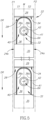
Fig. 5 is a detailed radial side view of the cutting tool shown inFig. 1 , 'flattened out' for illustrative purposes, with the associated cutting inserts and clamping screws removed; -
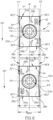
Fig. 6 is a detailed radial side view of the cutting tool shown inFig. 1 , 'flattened out' for illustrative purposes, with the associated cutting inserts retained therein; -
Fig. 7 is a top view of a cutting insert according to the present invention; -
Fig. 8 is a side view of the cutting insert shown inFig. 7 ; -
Fig. 9 is an end view of the cutting insert shown inFig. 7 ; -
Fig. 10 is a bottom view of the cutting insert shown inFig. 7 ; and -
Fig. 11 is a cross-sectional view of the cutting insert shown inFig. 9 , taken along the line XI-XI. - As shown in
Figs. 1 to 6 , the present invention relates to acutting tool 20 comprising a disk-shaped cutting body 22 having an axis of rotation R defining a direction of rotation DR about the axis of rotation R, two opposing first and secondbody end surfaces peripheral surface 26 extending therebetween. - A median plane M perpendicular to the axis of rotation R intersects the body
peripheral surface 26, and first and second planes P1, P2 are equidistantly offset from opposite first and second sides S1, S2 of the median plane M, respectively. - In some embodiments of the present invention, neither of the first and second planes P1, P2 may intersect the
cutting body 22. - In other embodiments of the present invention (not shown), the first and second planes P1, P2 may be annular shaped, thus ensuring that neither of the first and second planes P1, P2 intersect a raised central portion of the
cutting body 22. - According to a first aspect of the present invention, as shown in
Figs. 1 to 6 , a plurality of identicalinsert receiving pockets 28 are circumferentially spaced about the bodyperipheral surface 26 and an equal number of identicalindexable cutting inserts 30 are removably retained therein. - By virtue of the plurality of identical
insert receiving pockets 28 being identical, it should be appreciated that thecutting body 22 can be simply and cost-effectively manufactured. - In some embodiments of the present invention, the body
peripheral surface 26 may have a total of Ninsert receiving pockets 28 and exhibit N-fold rotational symmetry about the axis of rotation R. - Also in some embodiments of the present invention, the
cutting tool 20 may exhibit N/2-fold rotational symmetry about the axis of rotation R. - It should be appreciated that for embodiments of the present invention in which the
cutting tool 20 exhibits N/2-fold rotational symmetry about the axis of rotation R, N is an even number. - In some embodiments of the present invention, the
cutting inserts 30 may be manufactured by a suitably hard material, preferably by form pressing and sintering a cemented carbide, such as tungsten carbide, and thecutting body 22 may be manufactured from a less hard material. - As shown in
Figs. 2 to 5 , eachinsert receiving pocket 28 opens out to the first and secondbody end surfaces seat surface 32 and aback wall 34 shown in this embodiment as being transverse to theseat surface 32. - Also, as shown in
Figs. 2 to 5 , eachinsert receiving pocket 28 may open out to achip gullet 35, and eachchip gullet 35 may be located rotationally forward of its respectiveinsert receiving pocket 28, thus aiding chip evacuation. - In some embodiments of the present invention, each insert receiving pocket's
back wall 34 may be perpendicular to the median plane M. - Also in some embodiments of the present invention each insert receiving pocket's
back wall 34 may face in the direction of rotation DR. - As shown in
Fig. 5 , each insert receiving pocket'sseat surface 32 may have afloor surface 36 and first and secondlateral support surfaces lateral support surfaces - In some embodiments of the present invention, the
floor surface 36 and the first and secondlateral support surfaces seat surface 32 may be contiguous with theirrespective chip gullet 35. - Also in some embodiments of the present invention, the
floor surface 36 and the first and second lateral support surfaces 38a, 38b may be formed in acentral recess 40 of theseat surface 32, and the first and second lateral support surfaces 38a, 38b may face towards each other. - Further in some embodiments of the present invention, the first and second lateral support surfaces 38a, 38b may extend parallel to the median plane M. For such embodiments, the plurality of identical seat surfaces 32 can be simply and cost-effectively manufactured.
- Yet further in some embodiments of the present invention, each
seat surface 32 may include a planar raisedshoulder surface 41 partially surrounding thecentral recess 40. - As shown in
Figs. 7 to 11 , each cuttinginsert 30 has opposing upper andlower surfaces peripheral surface 46 therebetween and an insert axis A1 extending therethrough. - In some embodiments of the present invention, a through
bore 48 coaxial with the insert axis A1 may intersect the upper andlower surfaces - Also in some embodiments of the present invention, each cutting
insert 30 may not exhibit rotational symmetry about its insert axis A1. - As shown in
Figs. 8 to 10 , thelower surface 44 has a bearingsurface 50 and first and secondlower abutment surfaces - In some embodiments of the present invention, the first and second
lower abutment surfaces - Also in some embodiments of the present invention, the first and second
lower abutment surfaces - As shown in
Figs. 8 to 10 , the bearingsurface 50 and the first and secondlower abutment surfaces central boss 51 protruding from thelower surface 44. - In some embodiments of the present invention, the bearing
surface 50 may comprise at least twocoplanar bearing sub-surfaces - Also in some embodiments of the present invention, the
lower surface 44 may include aplanar bottom surface 55 surrounding thecentral boss 51. - As shown in
Fig. 10 , in a bottom view of one of the cutting inserts 30, the first and secondlower abutment surfaces - In some embodiments of the present invention, the first tilt angle α1 may be greater than 170 degrees and less than 180 degrees, and with 178 degrees shown in the illustrated example of
Fig. 10 . - Also in some embodiments of the present invention, the first tilt angle α1 may be an internal angle.
- It should be appreciated that use of the term "internal angle" throughout the description and claims refers to an angle between two planar surface components or zones as measured internal to the member on which the surface components or zones are formed, respectively.
- As shown in
Figs. 7 to 11 , the insertperipheral surface 46 has opposing first and secondinsert end surfaces insert side surfaces second cutting edges upper surface 42 and the first and secondinsert end surfaces - In some embodiments of the present invention, the
first cutting edge 58a may be interrupted by a firstchip dividing notch 60a, and thesecond cutting edge 58b may be interrupted by a secondchip dividing notch 60b. - Also in some embodiments of the present invention, the first and second
insert end surfaces insert side surface 56a, and the first and secondlower abutment surfaces insert side surface 56b. - Further in some embodiments of the present invention, each cutting
insert 30 may exhibit mirror symmetry about a vertical plane PV containing its insert axis A1 and intersecting its first and secondinsert side surfaces - According to the first aspect of the present invention, as shown in
Figs. 3 and 4 , each cutting insert'slower surface 44 is in contact with theseat surface 32 of its respectiveinsert receiving pocket 28, and circumferentially adjacent cutting inserts 30 have a different one of their first and secondinsert end surfaces back wall 34 of their respectiveinsert receiving pocket 28. - In some embodiments of the present invention, a clamping
screw 62 may extend through the throughbore 48 and threadingly engage a screw bore 64 in theseat surface 32. - Also in some embodiments of the present invention, as shown in
Figs. 2 and5 , the screw bore 64 may be formed in thefloor surface 36. - Further in some embodiments of the present invention, the screw bore 64 may have a screw axis A2 contained in the median plane M.
- Yet further in some embodiments of the present invention, the insert axis A1 of each cutting
insert 30 may be non-coaxial with the screw axis A2 of its respectiveinsert receiving pocket 28, and thus each throughbore 48 may be eccentrically positioned in relation to its respective screw bore 64. - Yet still further in some embodiments of the present invention, each insert's
bearing surface 50 may be in contact with thefloor surface 36 of its respectiveinsert receiving pocket 28. - As shown in
Fig. 4 , thebottom surface 55 may be spaced apart from the raisedshoulder surface 41 by a gap G. - As shown in
Fig. 6 , the median plane M may intersect the first andsecond cutting edges insert 30. - In some embodiments of the present invention, as shown in
Fig. 6 , each cutting insert's vertical plane PV may be non-perpendicular to the median plane M, albeit with a deviation of 1 degree therefrom. - According to the first aspect of the present invention, as shown in
Fig. 6 , the first plane P1 only intersects thefirst cutting edge 58a of every circumferentiallyalternate cutting insert 30 at a first intersection point I1 and none of thesecond cutting edges 58b, and the second plane P2 only intersects thesecond cutting edge 58b of every circumferentiallyalternate cutting insert 30 at asecond intersection point 12 and none of thefirst cutting edges 58a. - As shown in
Fig. 6 , the first andsecond cutting edges insert end surfaces back wall 34. - It should be appreciated that once the operative first and
second cutting edges insert 30 may be indexed in its respectiveinsert receiving pocket 28, such that the unworn first andsecond cutting edges - Alternatively, it should be appreciated that once the operative first and
second cutting edges insert 30 may be relocated to anotherinsert receiving pocket 28, such that the unworn first andsecond cutting edges first cutting edge 58a of every circumferentiallyalternate cutting insert 30 and none of thesecond cutting edges 58b, and the second plane P2 only intersects thesecond cutting edge 58b of every circumferentiallyalternate cutting insert 30 and none of thefirst cutting edges 58a. - In some embodiments of the invention, the first
chip dividing notches 60a associated with the operativefirst cutting edges 58a may be located on one side of the median plane M, and the secondchip dividing notches 60b associated with the operativesecond cutting edges 58b may be located on the opposite side of the median plane M. - It should be appreciated that the first and second
chip dividing notches - It should also be appreciated that the inclusion of different recessed or embossed shapes or letters, for example, "R" and "L" adjacent the first and
second cutting edges - As shown in
Fig. 6 , eachfirst cutting edge 58a may have first and second end points NE1, NE2 located on opposite sides of the median plane M, and eachsecond cutting edge 58b may have third and fourth end points NE3, NE4 located on opposite sides of the median plane M. - In some embodiments of the present invention, the first end point NE1 of each operative
first cutting edge 58a may be contained in the first plane P1 and thus coincident with its associated first intersection point 11, and the third end point NE3 of each operativesecond cutting edge 58b may be contained in the second plane P2 and thus coincident with its associatedsecond intersection point 12. For such embodiments of the present invention, the lateral distance between the first and second planes P1, P2 may define a maximum tool cutting width WMAX of thecutting tool 20. - As shown in
Fig. 6 , the second end point NE2 of each operativefirst cutting edge 58a may be located a first cutting width W1 from the first plane P1, and the fourth end point NE4 of each operativesecond cutting edge 58b may be located a second cutting width W2 from the second plane P2. - In some embodiments of the present invention, the first cutting width W1 may be at least nine tenths of the maximum tool cutting width WMAX, i.e. W1 ≥ WMAX ∗9/10, and the second cutting distance W2 may be at least nine tenths of the maximum tool cutting width WMAX i.e. W2 ≥ WMAX ∗9/10.
- Also in some embodiments of the present invention, the first cutting distance W1 may be equal to the second cutting distance W2.
- As shown in
Fig. 4 , each operativefirst cutting edge 58a may have an inclinedfirst end portion 66a extending from its first end point NE1 and forming an acute first end angle β1 of less than 60 degrees with median plane M, and each operativesecond cutting edge 58b may have an inclinedsecond end portion 66b extending from its third end point NE3 and forming an acute second end angle β2 of less than 60 degrees with median plane M. - In some embodiments of the present invention, the first and second end angles β1, β2 may be equal.
- It should be appreciated that for embodiments of the present invention having first and second end angles β1, β2 of less than 60 degrees, the cutting chip thickness will be suitably and advantageously reduced.
- In some embodiments of the present invention, the inclined
first end portion 66a of each operativefirst cutting edge 58a may laterally overlap the second cutting width W2, and the inclinedsecond end portion 66b of each operativesecond cutting edge 58b may laterally overlap the first cutting width W1. - It should be appreciated that for embodiments of the present invention in which the inclined first and
second end portions second cutting edges cutting tool 20 to perform cutting operations at suitably and advantageously high feed rates. - In some embodiments of the present invention, the first
lower abutment surface 52a of each cuttinginsert 30 having itsfirst cutting edge 58a operative, may be in contact with one of the first and second lateral support surfaces 38a, 38b located on one of the first and second sides S1, S2 of the median plane M, and the secondlower abutment surface 52b of each cuttinginsert 30 having itssecond cutting edge 58b operative, may be in contact with one of the first and second lateral support surfaces 38a, 38b located on the other one of the first and second sides S1, S2 of the median plane M . - Also in some embodiments of the present invention, the second
lower abutment surface 52b of each cuttinginsert 30 having itsfirst cutting edge 58a operative (e.g., see the lower part ofFig. 6 ), may not be in contact with any of the first and second lateral support surfaces 38a, 38b, and the firstlower abutment surface 52a of each cuttinginsert 30 having itssecond cutting edge 58b operative (e.g., see the upper part ofFig. 6 ), may not be in contact with any of the first and second lateral support surfaces 38a, 38b. - It should be appreciated that apart from the bearing
surface 50 being in contact with thefloor surface 36 and one of the first and secondlower abutment surfaces lower surface 44 is in contact with theseat surface 32 of its respectiveinsert receiving pocket 28. - It should also be appreciated that for embodiments of the present invention in which the
back wall 34 of eachinsert receiving pocket 28 is perpendicular to the median plane M and the first and second lateral support surfaces 38a, 38b of eachinsert receiving pocket 28 extend parallel to the median plane M, by virtue of one of the first and secondinsert end surfaces back wall 34, and one of the first and secondlower abutment surfaces insert 30 is retained its respectiveinsert receiving pocket 28 with a high level of stability. - In some embodiments of the present invention, the first
lower abutment surface 52a of each cuttinginsert 30 having itsfirst cutting edge 58a operative, may be in contact with the secondlateral support surface 38b, and the secondlower abutment surface 52b of each cuttinginsert 30 having itssecond cutting edge 58b operative, may be in contact with the firstlateral support surface 38a. - Also in some embodiments of the present invention, the first
lower abutment surface 52a of each cuttinginsert 30 having itsfirst cutting edge 58a operative, may be entirely located further from the first intersection point 11 than the secondlower abutment surface 52b, and the secondlower abutment surface 52b of each cuttinginsert 30 having itssecond cutting edge 58b operative, may be entirely located further from thesecond intersection point 12 than the firstlower abutment surface 52a. - It should be appreciated that for embodiments of the present invention in which the operative first or second
lower abutment surface insert 30 is on the opposite side of the median plane M from its associated first orsecond intersection point 11, 12, and further away from its associated first orsecond intersection point 11, 12 than its adjacent non-operative second or firstlower abutment surface lateral support surface lower abutment surface insert 30 caused by unbalanced cutting forces, which include cutting force components directed through the first and second intersection points 11, 12. - According to an additional aspect of the present invention, as shown in
Fig. 11 , in a cross-section taken in a horizontal plane PH perpendicular to the insert axis A1 and intersecting the insertperipheral surface 46 of one of the cutting inserts 30: - first and second peripheral corner points NC1, NC2 formed at the intersection of the first
insert end surface 54a and the first and secondinsert side surfaces - third and fourth peripheral corner points NC3, NC4 formed at the intersection of the second
insert end surface 54b and the first and secondinsert side surfaces - In some embodiments of the present invention, the first and second lateral sides SL1, SL2 may be equal in length, and the imaginary acute trapezoid T may be an isosceles trapezoid.
- Also in some embodiments of the present invention, the horizontal plane PH may be located closer to the
upper surface 42 than to thelower surface 44, and as shown inFig. 11 , no portion of the cuttinginsert 30 below the horizontal plane PH may extend outside the imaginary acute trapezoid T. - Further in some embodiments of the present invention, the first and second lateral sides SL1, SL2 may be bisected by first and second lateral bisectors BL1, BL2, and the first and second lateral bisectors BL1, BL2 may form an obtuse second tilt angle α2.
- Yet further in some embodiments of the present invention, the second tilt angle α2 may be equal to the first tilt angle α1 .
- As shown in
Fig. 7 , the first and second end points NE1, NE2 of thefirst cutting edge 58a define an imaginary first straight line L1, and the third and fourth end points NE3, NE4 of thesecond cutting edge 58b define an imaginary second line L2. - In some embodiments of the present invention, the imaginary first straight line L1 may be parallel to one of the first and second lateral sides SL1, SL2, and the imaginary second straight line L2 may be parallel to one of the first and second lateral sides SL1, SL2.
- As shown in
Figs. 7 to 11 , the imaginary first straight line L1 is parallel to the first lateral side SL1, and the imaginary second straight line L2 is parallel to the second lateral side SL2. - According to the "additional" aspect of the present invention described above with respect to
Fig. 11 , and with further reference toFig. 10 , in the bottom view of one of the cutting inserts 30, the first and secondlower abutment surfaces - In some embodiments of the present invention, the first and second
lower abutment surfaces peripheral surface 46. - Also in some embodiments of the present invention, as shown in
Fig. 10 , imaginary third and fourth straight lines L3, L4 extending parallel to the first and secondlower abutment surfaces - As shown in
Figs. 7 to 11 , the first and secondinsert end surfaces end abutment surfaces - In some embodiments of the present invention, as shown in
Fig. 8 , the horizontal plane PH may intersect the first and secondend abutment surfaces - As shown in
Fig. 3 , circumferentially adjacent cutting inserts 30 may have a different one of their first and secondend abutment surfaces back wall 34 of their respectiveinsert receiving pocket 28, and also such that each insert's horizontal plane PH intersects theback wall 34 of its respectiveinsert receiving pocket 28. - In some embodiments of the present invention, the first and second
end abutment surfaces - Also in some embodiments of the present invention, as shown in
Figs. 10 and11 , a first end plane E1 defined by the firstend abutment surface 68a may contain the first lateral side SL1, and a second end plane E2 defined by the secondend abutment surface 68b may contain the second lateral side SL2. - Further in some embodiments of the present invention, the second
end abutment surface 68b may be located on one side of the first end plane E1 and no portion of the cuttinginsert 30 may extend to the other side thereof, and the firstend abutment surface 68a may be located on one side of the second end plane E2 and no portion of the cuttinginsert 30 may extend to the other side thereof. - As shown in
Fig. 11 , the first and third peripheral corner points NC1, NC3 define the end points of a short base BS of the acute trapezoid T, and the second and fourth peripheral corner points NC2, NC4 define the end points of a long base BL of the acute trapezoid T. - As shown in
Fig. 10 , the first and secondlower abutment surfaces - In some embodiments of the present invention, the first and second
lower abutment surfaces - Also in some embodiments of the present invention, the vertical plane PV may contain the base bisector BB.
- In other embodiments of the present invention (not shown), the imaginary first straight line L1 may be parallel to the second lateral side SL2, and the imaginary second straight line L2 may be parallel to the first lateral side SL1, and thus the imaginary first and second straight lines L1, L2 associated with the operative first and
second cutting edges - Although the present invention has been described to a certain degree of particularity, it should be understood that various alterations and modifications could be made without departing from the spirit or scope of the invention as hereinafter claimed.
- The following aspects are preferred embodiments of the invention.
- 1. A cutting tool (20) comprising:
- a disk-shaped cutting body (22) having an axis of rotation (R) defining a direction of rotation (DR) about the axis of rotation (R), opposing first and second body end surfaces (24a, 24b) and a body peripheral surface (26) extending therebetween,
- a plurality of identical insert receiving pockets (28) circumferentially spaced about the body peripheral surface (26) and an equal number of identical indexable cutting inserts (30) removably retained therein,
- each insert receiving pocket (28) opening out to the first and second body end surfaces (24a, 24b), and having a seat surface (32) and a back wall (34) transverse to the seat surface (32), and
- each cutting insert (30) having opposing upper and lower surfaces (42, 44) and an insert peripheral surface (46) therebetween and an insert axis (A1) extending therethrough, the insert peripheral surface (46) having opposing first and second insert end surfaces (54a, 54b) spaced apart by opposing first and second insert side surfaces (56a, 56b), with first and second cutting edges (58a, 58b) formed at the intersection of the upper surface (42) and the first and second insert end surfaces (54a, 54b), respectively,
- wherein:
- each cutting insert's lower surface (44) is in contact with the seat surface (32) of its respective insert receiving pocket (28), and
- circumferentially adjacent cutting inserts (30) have a different one of their first and second insert end surfaces (54a, 54b) in contact with the back wall (34) of their respective insert receiving pocket (28),
- wherein:
- a median plane (M) perpendicular to the axis of rotation (R) intersects the body peripheral surface (26), and
- first and second planes (P1, P2) are equidistantly offset from opposite first and second sides (
S 1, S2) of the median plane (M), respectively, - and wherein:
- the first plane (P1) only intersects the first cutting edge (58a) of every circumferentially alternate cutting insert (30) at a first intersection point (I1) and none of the second cutting edges (58b), and
- the second plane (P2) only intersects the second cutting edge (58b) of every circumferentially alternate cutting insert (30) at a second intersection point (I2) and none of the first cutting edges (58a).
- 2. The cutting tool (20) according to
aspect 1, wherein the body peripheral surface (26) has a total of N insert receiving pockets (28) and exhibits N-fold rotational symmetry about the axis of rotation (R). - 3. The cutting tool (20) according to
aspect 1 or 2, wherein:
the first and second cutting edges (58a, 58b) intersecting the first and second (P1, P2), respectively, are operative and associated with first and second insert end surfaces (54a, 54b), respectively, not in contact with the back wall (34). - 4. The cutting tool (20) according to aspect 3, wherein:
- each insert receiving pocket's seat surface (32) has a floor surface (36) and first and second lateral support surfaces (38a, 38b) transverse thereto, the first and second lateral support surfaces (38a, 38b) located on the first and second sides (
S 1, S2) of the median plane (M), respectively, and - each cutting insert's lower surface (44) has a bearing surface (50) and first and second lower abutment surfaces (52a, 52b) transverse thereto,
- and wherein:
- the first lower abutment surface (52a) of each cutting insert (30) having its first cutting edge (58a) operative, is in contact with one of the first and second lateral support surfaces (38a, 38b) located on one of the first and second sides (
S 1, S2) of the median plane (M), and - the second lower abutment surface (52b) of each cutting insert (30) having its second cutting edge (58b) operative, is in contact with one of the first and second lateral support surfaces (38a, 38b) located on the other one of the first and second sides (S1, S2) of the median plane (M).
- the first lower abutment surface (52a) of each cutting insert (30) having its first cutting edge (58a) operative, is in contact with one of the first and second lateral support surfaces (38a, 38b) located on one of the first and second sides (
- each insert receiving pocket's seat surface (32) has a floor surface (36) and first and second lateral support surfaces (38a, 38b) transverse thereto, the first and second lateral support surfaces (38a, 38b) located on the first and second sides (
- 5. The cutting tool (20) according to aspect 4, wherein:
- the second lower abutment surface (52b) of each cutting insert (30) having its first cutting edge (58a) operative, is not in contact with any of the first and second lateral support surfaces (38a, 38b), and
- the first lower abutment surface (52a) of each cutting insert (30) having its second cutting edge (58b) operative, is not in contact with any of the first and second lateral support surfaces (38a, 38b).
- 6. The cutting tool (20) according to aspects 4 or 5, wherein in a bottom view of one of the cutting inserts (30):
the first and second lower abutment surfaces (52a, 52b) form an obtuse first tilt angle (α1). - 7. The cutting tool (20) according to any one of aspects 4 to 6, wherein:
- the floor surface (36) and the first and second lateral support surfaces (38a, 38b) are formed in a central recess (40) of the seat surface (32), and the first and second lateral support surfaces (38a, 38b) face towards each other, and
- the bearing surface (50) and the first and second lower abutment surfaces (52a, 52b) are formed on a central boss (51) protruding from the lower surface (44).
- 8. The cutting tool (20) according to any one of aspects 4 to 7, wherein:
- the first lower abutment surface (52a) of each cutting insert (30) having its first cutting edge (58a) operative, is in contact with the second lateral support surface (38b), and
- the second lower abutment surface (52b) of each cutting insert (30) having its second cutting edge (58b) operative, is in contact with the first lateral support surface (38a).
- 9. The cutting tool (20) according to any one of aspects 3 to 8, wherein:
- each first cutting edge (58a) has first and second end points (NE1, NE2) located on opposite sides of the median plane (M), and
- each second cutting edge (58b) has third and fourth end points (NE3, NE4) located on opposite sides of the median plane (M).
- 10. The cutting tool (20) according to aspect 9, wherein:
- the first end point (NE1) of each operative first cutting edge (58a) is contained in the first plane (P1),
- the third end point (NE3) of each operative second cutting edge (58b) is contained in the second plane (P1), and
- the lateral distance between the first and second planes (P1, P2) defines a maximum tool cutting width (WMAX).
- 11. The cutting tool (20) according to aspect 10, wherein:
- the second end point (NE2) of each operative first cutting edge (58a) is located a first cutting width (W1) from the first plane (P1), and
- the fourth end point (NE4) of each operative second cutting edge (58b) is located a second cutting width (W2) from the second plane (P2),
- and wherein:
- the first cutting width (W1) is at least nine tenths of the maximum tool cutting width (WMAX), and
- the second cutting width (W2) is at least nine tenths of the maximum tool cutting width (WMAX).
- 12. The cutting tool (20) according to any one of the preceding aspects, wherein each cutting insert (30) does not exhibit rotational symmetry about its insert axis (A1).
- 13. The cutting tool (20) according to any one of the preceding aspect, wherein each insert receiving pocket's back wall (34) faces in the direction of rotation (DR).
- 14. An indexable cutting insert (30) comprising:
- opposing upper and lower surfaces (42, 44) and an insert peripheral surface (46) therebetween and an insert axis (A1) extending therethrough,
- the lower surface (44) having a bearing surface (50) and first and second lower abutment surfaces (52a, 52b) transverse thereto, and
- the insert peripheral surface (46) having opposing first and second insert end surfaces (54a, 54b) spaced apart by opposing first and second insert side surfaces (56a, 56b), with first and second cutting edges (58a, 58b) formed at the intersection of the upper surface (42) and the first and second insert end surfaces (54a, 54b), respectively,
- wherein in a cross-section taken in a horizontal plane (PH) perpendicular to the insert axis (A1) and intersecting the insert peripheral surface (46):
- first and second peripheral corner points (NC1, NC2) formed at the intersection of the first insert end surface (54a) and the first and second insert side surfaces (56a, 56b), respectively, define the end points of a first lateral side (SL1) of an imaginary acute trapezoid (T),
- third and fourth peripheral corner points (NC3, NC4) formed at the intersection of the second insert end surface (54b) and the first and second insert side surfaces (56a, 56b), respectively, define the end points of a second lateral side (SL2) of the imaginary acute trapezoid (T), and
- the first and third peripheral corner points (NC1, NC3) define the end points of a short base (BS) of the acute trapezoid (T), and the second and fourth peripheral corner points (NC2, NC4) define the end points of a long base (BL) of the acute trapezoid (T),
- and wherein in a bottom view of the cutting insert (30):
the first and second lower abutment surfaces (52a, 52b) form an obtuse first tilt angle (α1) and are located inside the imaginary acute trapezoid (T).
- opposing upper and lower surfaces (42, 44) and an insert peripheral surface (46) therebetween and an insert axis (A1) extending therethrough,
- 15. The cutting insert (30) according to aspect 14, wherein:
- the horizontal plane (PH) is located closer to the upper surface (42) than to the lower surface (44), and
- no portion of the cutting insert (30) below the horizontal plane (PH) extends outside the imaginary acute trapezoid (T).
- 16. The cutting insert (30) according to aspect 14 or 15, wherein in the bottom view:
the first and second lower abutment surfaces (52a, 52b) face towards the long base (BL). - 17. The cutting insert (30) according to any one of aspects 14 to 16, wherein in the bottom view:
imaginary third and fourth straight lines (L3, L4) extending parallel to the first and second lower abutment surfaces (52a, 52b), respectively, are perpendicular to the first and second lateral sides (SL1, SL2), respectively. - 18. The cutting insert (30) according to any one of aspects 14 to 17, wherein:
- the first and second lateral sides (SL1, SL2) are bisected by first and second lateral bisectors (BL1, BL2),
- the first and second lateral bisectors (BL1, BL2) form an obtuse second tilt angle (α2), and
- the second tilt angle (α2) is equal to the first tilt angle (α1).
- 19. The cutting insert (30) according to any one of aspects 14 to 18, exhibiting mirror symmetry about a vertical plane (PV) containing the insert axis (A1) and intersecting the first and second insert side surfaces (56a, 56b).
- 20. The cutting insert (30) according to any one of aspects 14 to 19, wherein:
the bearing surface (50) and the first and second lower abutment surfaces (52a, 52b) are formed on a central boss (51) protruding from the lower surface (44). - 21. The cutting insert (30) according to any one of aspects 14 to 20, wherein the first tilt angle (α1) is an internal angle.
Claims (8)
- An indexable cutting insert (30) comprising:opposing upper and lower surfaces (42, 44) and an insert peripheral surface (46) therebetween and an insert axis (A1) extending therethrough,the lower surface (44) having a bearing surface (50) and first and second lower abutment surfaces (52a, 52b) transverse thereto, andthe insert peripheral surface (46) having opposing first and second insert end surfaces (54a, 54b) spaced apart by opposing first and second insert side surfaces (56a, 56b), with first and second cutting edges (58a, 58b) formed at the intersection of the upper surface (42) and the first and second insert end surfaces (54a, 54b), respectively,characterized in that:
in a cross-section taken in a horizontal plane (PH) perpendicular to the insert axis (A1) and intersecting the insert peripheral surface (46):first and second peripheral corner points (NC1, NC2) formed at the intersection of the first insert end surface (54a) and the first and second insert side surfaces (56a, 56b), respectively, define the end points of a first lateral side (SL1) of an imaginary acute trapezoid (T),third and fourth peripheral corner points (NC3, NC4) formed at the intersection of the second insert end surface (54b) and the first and second insert side surfaces (56a, 56b), respectively, define the end points of a second lateral side (SL2) of the imaginary acute trapezoid (T), andthe first and third peripheral corner points (NC1, NC3) define the end points of a short base (BS) of the acute trapezoid (T), and the second and fourth peripheral corner points (NC2, NC4) define the end points of a long base (BL) of the acute trapezoid (T),and in a bottom view of the cutting insert (30):
the first and second lower abutment surfaces (52a, 52b) form an obtuse first tilt angle (α1) and are located inside the imaginary acute trapezoid (T). - The cutting insert (30) according to claim 1, wherein:the horizontal plane (PH) is located closer to the upper surface (42) than to the lower surface (44), andno portion of the cutting insert (30) below the horizontal plane (PH) extends outside the imaginary acute trapezoid (T).
- The cutting insert (30) according to claim 1 or 2, wherein in the bottom view:
the first and second lower abutment surfaces (52a, 52b) face towards the long base (BL). - The cutting insert (30) according to any one of the preceding claims, wherein in the bottom view:
imaginary third and fourth straight lines (L3, L4) extending parallel to the first and second lower abutment surfaces (52a, 52b), respectively, are perpendicular to the first and second lateral sides (SL1, SL2), respectively. - The cutting insert (30) according to any one of the preceding claims, wherein:the first and second lateral sides (SL1, SL2) are bisected by first and second lateral bisectors (BL1, BL2),the first and second lateral bisectors (BL1, BL2) form an obtuse second tilt angle (α2), andthe second tilt angle (α2) is equal to the first tilt angle (α1).
- The cutting insert (30) according to any one of the preceding claims, exhibiting mirror symmetry about a vertical plane (PV) containing the insert axis (A1) and intersecting the first and second insert side surfaces (56a, 56b).
- The cutting insert (30) according to any one of the preceding claims, wherein:
the bearing surface (50) and the first and second lower abutment surfaces (52a, 52b) are formed on a central boss (51) protruding from the lower surface (44). - The cutting insert (30) according to any one of the preceding claims, wherein the first tilt angle (α1) is an internal angle.
Applications Claiming Priority (3)
| Application Number | Priority Date | Filing Date | Title |
|---|---|---|---|
| US15/815,836 US10525537B2 (en) | 2017-11-17 | 2017-11-17 | Rotary cutting tool having disk-shaped cutting body and indexable cutting insert therefor |
| EP18797166.8A EP3710190B1 (en) | 2017-11-17 | 2018-10-18 | Rotary cutting tool having disk-shaped cutting body |
| PCT/IL2018/051116 WO2019097504A1 (en) | 2017-11-17 | 2018-10-18 | Rotary cutting tool having disk-shaped cutting body and indexable cutting insert therefor |
Related Parent Applications (2)
| Application Number | Title | Priority Date | Filing Date |
|---|---|---|---|
| EP18797166.8A Division-Into EP3710190B1 (en) | 2017-11-17 | 2018-10-18 | Rotary cutting tool having disk-shaped cutting body |
| EP18797166.8A Division EP3710190B1 (en) | 2017-11-17 | 2018-10-18 | Rotary cutting tool having disk-shaped cutting body |
Publications (4)
| Publication Number | Publication Date |
|---|---|
| EP4289538A2 true EP4289538A2 (en) | 2023-12-13 |
| EP4289538A3 EP4289538A3 (en) | 2024-02-28 |
| EP4289538B1 EP4289538B1 (en) | 2025-05-14 |
| EP4289538C0 EP4289538C0 (en) | 2025-05-14 |
Family
ID=64109982
Family Applications (2)
| Application Number | Title | Priority Date | Filing Date |
|---|---|---|---|
| EP18797166.8A Active EP3710190B1 (en) | 2017-11-17 | 2018-10-18 | Rotary cutting tool having disk-shaped cutting body |
| EP23193269.0A Active EP4289538B1 (en) | 2017-11-17 | 2018-10-18 | Rotary cutting tool having disk-shaped cutting body and indexable cutting insert therefor |
Family Applications Before (1)
| Application Number | Title | Priority Date | Filing Date |
|---|---|---|---|
| EP18797166.8A Active EP3710190B1 (en) | 2017-11-17 | 2018-10-18 | Rotary cutting tool having disk-shaped cutting body |
Country Status (11)
| Country | Link |
|---|---|
| US (1) | US10525537B2 (en) |
| EP (2) | EP3710190B1 (en) |
| JP (1) | JP7210572B2 (en) |
| KR (1) | KR102520529B1 (en) |
| CN (1) | CN111315517B (en) |
| BR (1) | BR112020009213A2 (en) |
| CA (1) | CA3079675A1 (en) |
| IL (1) | IL274242B2 (en) |
| PL (2) | PL3710190T3 (en) |
| TW (1) | TWI768117B (en) |
| WO (1) | WO2019097504A1 (en) |
Citations (2)
| Publication number | Priority date | Publication date | Assignee | Title |
|---|---|---|---|---|
| WO2010083541A1 (en) | 2009-01-22 | 2010-07-29 | Linsinger Maschinenbau Gmbh | Side milling cutter tool and cutting element |
| JP2015196203A (en) | 2014-03-31 | 2015-11-09 | 三菱マテリアル株式会社 | Replaceable metal saw |
Family Cites Families (20)
| Publication number | Priority date | Publication date | Assignee | Title |
|---|---|---|---|---|
| JPS59132723U (en) * | 1983-02-24 | 1984-09-05 | 兼房刃物工業株式会社 | Chipsaw |
| US4690024A (en) * | 1985-02-28 | 1987-09-01 | Black & Decker Inc. | Saw blade and tip therefor |
| JPH0760525A (en) * | 1993-08-28 | 1995-03-07 | Retsu Gomi | Milling cutter |
| SE511567C2 (en) * | 1997-04-18 | 1999-10-18 | Sandvik Ab | Inserts for disc cutters, and disc cutters including such inserts |
| IL129297A (en) * | 1998-07-13 | 2002-12-01 | Iscar Ltd | Tangential cutting insert |
| IL140104A (en) * | 2000-12-05 | 2006-06-11 | Amir Satran | Rotary cutting tool |
| IL165621A (en) * | 2004-12-07 | 2008-06-05 | Iscar Ltd | Cutting tool and cutting insert therefor |
| DE102006034673A1 (en) | 2006-07-24 | 2008-01-31 | Walter Ag | crankshaft cutters |
| DE102007011395A1 (en) | 2007-03-07 | 2008-09-11 | Linsinger-Maschinenbau Gmbh | Side-milling cutter tool for cutting element to mill and saw metal blanks, has disk shaped base body and multiple interchangeable cutting elements, particularly hard metal cutters are arranged on boundary area of disk shaped base body |
| RU2567640C2 (en) * | 2010-11-03 | 2015-11-10 | Секо Тулз Аб | Cutting tool with inserts of several types |
| EP2450138B1 (en) | 2010-11-03 | 2013-10-16 | Seco Tools Ab | Cutting insert with grooved surface defining plural support surfaces |
| CN103492110B (en) * | 2011-04-26 | 2015-11-25 | 株式会社钨钛合金 | Cutting inserts and cutting tools |
| IL214782A (en) | 2011-08-22 | 2016-02-29 | Iscar Ltd | Cutting and milling |
| US9033621B2 (en) * | 2011-09-19 | 2015-05-19 | Iscar, Ltd. | Cutting insert, cutting body and clamping mechanism of a cutting tool assembly for chip removal |
| KR101318583B1 (en) * | 2011-12-06 | 2013-10-15 | 한국야금 주식회사 | Insert for slot milling cutter |
| CN104114307B (en) * | 2012-02-20 | 2016-01-20 | 株式会社钨钛合金 | Cutting tip and bit replacing formula cutting element |
| JP6127343B2 (en) * | 2013-03-26 | 2017-05-17 | 住友電工ハードメタル株式会社 | Cutting insert for milling cutter |
| TWI494182B (en) * | 2014-07-28 | 2015-08-01 | 張新添 | Discarded structure of discarded blades |
| KR102252055B1 (en) * | 2014-12-05 | 2021-05-17 | 대구텍 유한책임회사 | Rotary cutting tool and cutting insert thereof |
| CN106180894B (en) * | 2016-08-25 | 2018-09-14 | 唐山冶金锯片有限公司 | A kind of double-sided blade sawtooth cutter block, machine card type saw blade and double-sided blade sawtooth cutter block interchanging method |
-
2017
- 2017-11-17 US US15/815,836 patent/US10525537B2/en active Active
-
2018
- 2018-09-10 TW TW107131657A patent/TWI768117B/en not_active IP Right Cessation
- 2018-10-18 CA CA3079675A patent/CA3079675A1/en active Pending
- 2018-10-18 PL PL18797166.8T patent/PL3710190T3/en unknown
- 2018-10-18 CN CN201880072209.5A patent/CN111315517B/en active Active
- 2018-10-18 IL IL274242A patent/IL274242B2/en unknown
- 2018-10-18 EP EP18797166.8A patent/EP3710190B1/en active Active
- 2018-10-18 PL PL23193269.0T patent/PL4289538T3/en unknown
- 2018-10-18 JP JP2020522965A patent/JP7210572B2/en active Active
- 2018-10-18 KR KR1020207017223A patent/KR102520529B1/en active Active
- 2018-10-18 BR BR112020009213-4A patent/BR112020009213A2/en not_active Application Discontinuation
- 2018-10-18 WO PCT/IL2018/051116 patent/WO2019097504A1/en not_active Ceased
- 2018-10-18 EP EP23193269.0A patent/EP4289538B1/en active Active
Patent Citations (2)
| Publication number | Priority date | Publication date | Assignee | Title |
|---|---|---|---|---|
| WO2010083541A1 (en) | 2009-01-22 | 2010-07-29 | Linsinger Maschinenbau Gmbh | Side milling cutter tool and cutting element |
| JP2015196203A (en) | 2014-03-31 | 2015-11-09 | 三菱マテリアル株式会社 | Replaceable metal saw |
Also Published As
| Publication number | Publication date |
|---|---|
| KR102520529B1 (en) | 2023-04-12 |
| US20190151963A1 (en) | 2019-05-23 |
| TW201922388A (en) | 2019-06-16 |
| PL4289538T3 (en) | 2025-09-08 |
| EP3710190A1 (en) | 2020-09-23 |
| EP3710190B1 (en) | 2024-07-03 |
| EP4289538B1 (en) | 2025-05-14 |
| EP4289538C0 (en) | 2025-05-14 |
| JP2021503376A (en) | 2021-02-12 |
| EP4289538A3 (en) | 2024-02-28 |
| PL3710190T3 (en) | 2024-10-28 |
| KR20200085866A (en) | 2020-07-15 |
| EP3710190C0 (en) | 2024-07-03 |
| CA3079675A1 (en) | 2019-05-23 |
| TWI768117B (en) | 2022-06-21 |
| RU2020112868A (en) | 2021-12-17 |
| CN111315517B (en) | 2023-12-08 |
| BR112020009213A2 (en) | 2020-10-20 |
| RU2020112868A3 (en) | 2022-01-19 |
| CN111315517A (en) | 2020-06-19 |
| IL274242B1 (en) | 2023-07-01 |
| WO2019097504A1 (en) | 2019-05-23 |
| IL274242B2 (en) | 2023-11-01 |
| IL274242A (en) | 2020-06-30 |
| US10525537B2 (en) | 2020-01-07 |
| JP7210572B2 (en) | 2023-01-23 |
Similar Documents
| Publication | Publication Date | Title |
|---|---|---|
| US9120156B2 (en) | Rhombus-shaped indexable cutting insert and cutting tool | |
| US8708613B2 (en) | Left-handed and right-handed cutting tool | |
| US20140227051A1 (en) | Single-Sided Square-Shaped Indexable Cutting Insert and Cutting Tool | |
| CN108778589A (en) | Cutting tip, cutter holder and cutter | |
| TWI737885B (en) | Indexable, single-sided cutting insert having two clamping bores and cutting tool therefor | |
| CN103128350A (en) | A cutting insert and a milling tool | |
| EP3717162A1 (en) | Slitting cutter and tool key in combination therewith | |
| JP5988010B2 (en) | Cutting inserts, tool bodies and cutting tools | |
| WO2014161658A1 (en) | Indexable double-sided milling cutting insert | |
| EP4072762B1 (en) | Cutting insert having two upper cutting edges and a lower central protuberance with four abutment walls defining an imaginary quadrilateral, and rotary cutting tool | |
| EP3710190B1 (en) | Rotary cutting tool having disk-shaped cutting body | |
| RU2776248C2 (en) | Rotary cutting tool with disc-shaped cutting case and indexed cutting insert for it | |
| US10406611B1 (en) | Cutting tool and cutting insert having complementary engagement features for eccentric mounting |
Legal Events
| Date | Code | Title | Description |
|---|---|---|---|
| PUAI | Public reference made under article 153(3) epc to a published international application that has entered the european phase |
Free format text: ORIGINAL CODE: 0009012 |
|
| STAA | Information on the status of an ep patent application or granted ep patent |
Free format text: STATUS: REQUEST FOR EXAMINATION WAS MADE |
|
| 17P | Request for examination filed |
Effective date: 20230915 |
|
| AC | Divisional application: reference to earlier application |
Ref document number: 3710190 Country of ref document: EP Kind code of ref document: P |
|
| AK | Designated contracting states |
Kind code of ref document: A2 Designated state(s): AL AT BE BG CH CY CZ DE DK EE ES FI FR GB GR HR HU IE IS IT LI LT LU LV MC MK MT NL NO PL PT RO RS SE SI SK SM TR |
|
| REG | Reference to a national code |
Ref country code: DE Ref legal event code: R079 Free format text: PREVIOUS MAIN CLASS: B23C0005200000 Ipc: B23C0005080000 Ref country code: DE Ref legal event code: R079 Ref document number: 602018082052 Country of ref document: DE Free format text: PREVIOUS MAIN CLASS: B23C0005200000 Ipc: B23C0005080000 |
|
| PUAL | Search report despatched |
Free format text: ORIGINAL CODE: 0009013 |
|
| AK | Designated contracting states |
Kind code of ref document: A3 Designated state(s): AL AT BE BG CH CY CZ DE DK EE ES FI FR GB GR HR HU IE IS IT LI LT LU LV MC MK MT NL NO PL PT RO RS SE SI SK SM TR |
|
| RIC1 | Information provided on ipc code assigned before grant |
Ipc: B23C 5/22 20060101ALI20240124BHEP Ipc: B23C 5/20 20060101ALI20240124BHEP Ipc: B23C 5/08 20060101AFI20240124BHEP |
|
| RIC1 | Information provided on ipc code assigned before grant |
Ipc: B23C 5/22 20060101ALI20241031BHEP Ipc: B23C 5/20 20060101ALI20241031BHEP Ipc: B23C 5/08 20060101AFI20241031BHEP |
|
| GRAP | Despatch of communication of intention to grant a patent |
Free format text: ORIGINAL CODE: EPIDOSNIGR1 |
|
| STAA | Information on the status of an ep patent application or granted ep patent |
Free format text: STATUS: GRANT OF PATENT IS INTENDED |
|
| INTG | Intention to grant announced |
Effective date: 20241216 |
|
| GRAS | Grant fee paid |
Free format text: ORIGINAL CODE: EPIDOSNIGR3 |
|
| GRAA | (expected) grant |
Free format text: ORIGINAL CODE: 0009210 |
|
| STAA | Information on the status of an ep patent application or granted ep patent |
Free format text: STATUS: THE PATENT HAS BEEN GRANTED |
|
| AC | Divisional application: reference to earlier application |
Ref document number: 3710190 Country of ref document: EP Kind code of ref document: P |
|
| AK | Designated contracting states |
Kind code of ref document: B1 Designated state(s): AL AT BE BG CH CY CZ DE DK EE ES FI FR GB GR HR HU IE IS IT LI LT LU LV MC MK MT NL NO PL PT RO RS SE SI SK SM TR |
|
| REG | Reference to a national code |
Ref country code: GB Ref legal event code: FG4D |
|
| REG | Reference to a national code |
Ref country code: CH Ref legal event code: EP |
|
| REG | Reference to a national code |
Ref country code: DE Ref legal event code: R096 Ref document number: 602018082052 Country of ref document: DE |
|
| REG | Reference to a national code |
Ref country code: IE Ref legal event code: FG4D |
|
| U01 | Request for unitary effect filed |
Effective date: 20250519 |
|
| U07 | Unitary effect registered |
Designated state(s): AT BE BG DE DK EE FI FR IT LT LU LV MT NL PT RO SE SI Effective date: 20250523 |
|
| PG25 | Lapsed in a contracting state [announced via postgrant information from national office to epo] |
Ref country code: ES Free format text: LAPSE BECAUSE OF FAILURE TO SUBMIT A TRANSLATION OF THE DESCRIPTION OR TO PAY THE FEE WITHIN THE PRESCRIBED TIME-LIMIT Effective date: 20250514 |
|
| PG25 | Lapsed in a contracting state [announced via postgrant information from national office to epo] |
Ref country code: NO Free format text: LAPSE BECAUSE OF FAILURE TO SUBMIT A TRANSLATION OF THE DESCRIPTION OR TO PAY THE FEE WITHIN THE PRESCRIBED TIME-LIMIT Effective date: 20250814 Ref country code: GR Free format text: LAPSE BECAUSE OF FAILURE TO SUBMIT A TRANSLATION OF THE DESCRIPTION OR TO PAY THE FEE WITHIN THE PRESCRIBED TIME-LIMIT Effective date: 20250815 |
|
| PG25 | Lapsed in a contracting state [announced via postgrant information from national office to epo] |
Ref country code: HR Free format text: LAPSE BECAUSE OF FAILURE TO SUBMIT A TRANSLATION OF THE DESCRIPTION OR TO PAY THE FEE WITHIN THE PRESCRIBED TIME-LIMIT Effective date: 20250514 |
|
| PG25 | Lapsed in a contracting state [announced via postgrant information from national office to epo] |
Ref country code: RS Free format text: LAPSE BECAUSE OF FAILURE TO SUBMIT A TRANSLATION OF THE DESCRIPTION OR TO PAY THE FEE WITHIN THE PRESCRIBED TIME-LIMIT Effective date: 20250814 |
|
| U20 | Renewal fee for the european patent with unitary effect paid |
Year of fee payment: 8 Effective date: 20250912 |
|
| PG25 | Lapsed in a contracting state [announced via postgrant information from national office to epo] |
Ref country code: IS Free format text: LAPSE BECAUSE OF FAILURE TO SUBMIT A TRANSLATION OF THE DESCRIPTION OR TO PAY THE FEE WITHIN THE PRESCRIBED TIME-LIMIT Effective date: 20250914 |
|
| PG25 | Lapsed in a contracting state [announced via postgrant information from national office to epo] |
Ref country code: SM Free format text: LAPSE BECAUSE OF FAILURE TO SUBMIT A TRANSLATION OF THE DESCRIPTION OR TO PAY THE FEE WITHIN THE PRESCRIBED TIME-LIMIT Effective date: 20250514 |
|
| PG25 | Lapsed in a contracting state [announced via postgrant information from national office to epo] |
Ref country code: CZ Free format text: LAPSE BECAUSE OF FAILURE TO SUBMIT A TRANSLATION OF THE DESCRIPTION OR TO PAY THE FEE WITHIN THE PRESCRIBED TIME-LIMIT Effective date: 20250514 |
|
| PG25 | Lapsed in a contracting state [announced via postgrant information from national office to epo] |
Ref country code: SK Free format text: LAPSE BECAUSE OF FAILURE TO SUBMIT A TRANSLATION OF THE DESCRIPTION OR TO PAY THE FEE WITHIN THE PRESCRIBED TIME-LIMIT Effective date: 20250514 |
|
| PLBE | No opposition filed within time limit |
Free format text: ORIGINAL CODE: 0009261 |
|
| STAA | Information on the status of an ep patent application or granted ep patent |
Free format text: STATUS: NO OPPOSITION FILED WITHIN TIME LIMIT |
|
| REG | Reference to a national code |
Ref country code: CH Ref legal event code: L10 Free format text: ST27 STATUS EVENT CODE: U-0-0-L10-L00 (AS PROVIDED BY THE NATIONAL OFFICE) Effective date: 20260325 |
|
| 26N | No opposition filed |
Effective date: 20260217 |
|
| REG | Reference to a national code |
Ref country code: CH Ref legal event code: H13 Free format text: ST27 STATUS EVENT CODE: U-0-0-H10-H13 (AS PROVIDED BY THE NATIONAL OFFICE) Effective date: 20260527 |
|
| GBPC | Gb: european patent ceased through non-payment of renewal fee |
Effective date: 20251018 |
|
| PG25 | Lapsed in a contracting state [announced via postgrant information from national office to epo] |
Ref country code: MC Free format text: LAPSE BECAUSE OF FAILURE TO SUBMIT A TRANSLATION OF THE DESCRIPTION OR TO PAY THE FEE WITHIN THE PRESCRIBED TIME-LIMIT Effective date: 20250514 |
|
| PG25 | Lapsed in a contracting state [announced via postgrant information from national office to epo] |
Ref country code: GB Free format text: LAPSE BECAUSE OF NON-PAYMENT OF DUE FEES Effective date: 20251018 |
|
| PG25 | Lapsed in a contracting state [announced via postgrant information from national office to epo] |
Ref country code: CH Free format text: LAPSE BECAUSE OF NON-PAYMENT OF DUE FEES Effective date: 20251031 |