EP4287566A1 - High-efficiency transmission ethernet device - Google Patents
High-efficiency transmission ethernet device Download PDFInfo
- Publication number
- EP4287566A1 EP4287566A1 EP22207108.6A EP22207108A EP4287566A1 EP 4287566 A1 EP4287566 A1 EP 4287566A1 EP 22207108 A EP22207108 A EP 22207108A EP 4287566 A1 EP4287566 A1 EP 4287566A1
- Authority
- EP
- European Patent Office
- Prior art keywords
- data
- ethernet
- frames
- packets
- routine
- Prior art date
- Legal status (The legal status is an assumption and is not a legal conclusion. Google has not performed a legal analysis and makes no representation as to the accuracy of the status listed.)
- Granted
Links
Images


Classifications
-
- H—ELECTRICITY
- H04—ELECTRIC COMMUNICATION TECHNIQUE
- H04L—TRANSMISSION OF DIGITAL INFORMATION, e.g. TELEGRAPHIC COMMUNICATION
- H04L12/00—Data switching networks
- H04L12/28—Data switching networks characterised by path configuration, e.g. LAN [Local Area Networks] or WAN [Wide Area Networks]
- H04L12/46—Interconnection of networks
- H04L12/4633—Interconnection of networks using encapsulation techniques, e.g. tunneling
-
- H—ELECTRICITY
- H04—ELECTRIC COMMUNICATION TECHNIQUE
- H04L—TRANSMISSION OF DIGITAL INFORMATION, e.g. TELEGRAPHIC COMMUNICATION
- H04L45/00—Routing or path finding of packets in data switching networks
- H04L45/66—Layer 2 routing, e.g. in Ethernet based MAN's
-
- H—ELECTRICITY
- H04—ELECTRIC COMMUNICATION TECHNIQUE
- H04L—TRANSMISSION OF DIGITAL INFORMATION, e.g. TELEGRAPHIC COMMUNICATION
- H04L47/00—Traffic control in data switching networks
- H04L47/10—Flow control; Congestion control
- H04L47/41—Flow control; Congestion control by acting on aggregated flows or links
-
- H—ELECTRICITY
- H04—ELECTRIC COMMUNICATION TECHNIQUE
- H04L—TRANSMISSION OF DIGITAL INFORMATION, e.g. TELEGRAPHIC COMMUNICATION
- H04L49/00—Packet switching elements
- H04L49/90—Buffering arrangements
- H04L49/9057—Arrangements for supporting packet reassembly or resequencing
-
- H—ELECTRICITY
- H04—ELECTRIC COMMUNICATION TECHNIQUE
- H04L—TRANSMISSION OF DIGITAL INFORMATION, e.g. TELEGRAPHIC COMMUNICATION
- H04L67/00—Network arrangements or protocols for supporting network services or applications
- H04L67/50—Network services
- H04L67/56—Provisioning of proxy services
- H04L67/566—Grouping or aggregating service requests, e.g. for unified processing
-
- H—ELECTRICITY
- H04—ELECTRIC COMMUNICATION TECHNIQUE
- H04L—TRANSMISSION OF DIGITAL INFORMATION, e.g. TELEGRAPHIC COMMUNICATION
- H04L69/00—Network arrangements, protocols or services independent of the application payload and not provided for in the other groups of this subclass
- H04L69/22—Parsing or analysis of headers
-
- H—ELECTRICITY
- H04—ELECTRIC COMMUNICATION TECHNIQUE
- H04L—TRANSMISSION OF DIGITAL INFORMATION, e.g. TELEGRAPHIC COMMUNICATION
- H04L2212/00—Encapsulation of packets
-
- H—ELECTRICITY
- H04—ELECTRIC COMMUNICATION TECHNIQUE
- H04L—TRANSMISSION OF DIGITAL INFORMATION, e.g. TELEGRAPHIC COMMUNICATION
- H04L49/00—Packet switching elements
- H04L49/35—Switches specially adapted for specific applications
- H04L49/351—Switches specially adapted for specific applications for local area network [LAN], e.g. Ethernet switches
-
- Y—GENERAL TAGGING OF NEW TECHNOLOGICAL DEVELOPMENTS; GENERAL TAGGING OF CROSS-SECTIONAL TECHNOLOGIES SPANNING OVER SEVERAL SECTIONS OF THE IPC; TECHNICAL SUBJECTS COVERED BY FORMER USPC CROSS-REFERENCE ART COLLECTIONS [XRACs] AND DIGESTS
- Y02—TECHNOLOGIES OR APPLICATIONS FOR MITIGATION OR ADAPTATION AGAINST CLIMATE CHANGE
- Y02D—CLIMATE CHANGE MITIGATION TECHNOLOGIES IN INFORMATION AND COMMUNICATION TECHNOLOGIES [ICT], I.E. INFORMATION AND COMMUNICATION TECHNOLOGIES AIMING AT THE REDUCTION OF THEIR OWN ENERGY USE
- Y02D30/00—Reducing energy consumption in communication networks
Definitions
- the invention relates to the technical field of communication devices, and more particularly, to a high-efficiency transmission Ethernet device.
- Ethernet is a communication protocol standard that is by far the most commonly used in local area network (LAN) and it was developed in the earlier 1970s. Ethernet is a commonly used LAN standard transmitting data with a transmitting speed at 10/100/1000/2500/1000OMbps.
- an Ethernet device consists of a shared transmission medium, for example, a twisted-pair cable or a coaxial cable, a multiport hub, a bridge or a switch. In a star or bus configuration, the hub/switch/bridge connects computers, printers and workstations to each other with a cable.
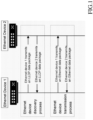
- the first stage is an Ethernet device discovery process.
- the Ethernet device After startup, the Ethernet device sends its main capabilities, such as the management address, device identity and interface identity, to the other Ethernet devices connected to the same local area network through LLDP (Link layer Discovery protocol).
- LLDP Link layer Discovery protocol
- the Ethernet device obtains information corresponding to the other devices in the same local area network.
- the Ethernet device sends, according to capabilities of Ethernet devices at the peer, Ethernet packets (Ethernet frames) that the Ethernet devices at the peer can process, based on the information obtained in the first stage, thereby enabling communication among different Ethernet devices.
- Ethernet data packets used in this process are called Ethernet frames.
- a format of each of the Ethernet frame is shown in Figure 2 .
- the one Ethernet frame comprises a preamble, a start frame delimiter, data, a redundancy check and an interframe gap.
- the preamble is 7 bytes long with a default value of 7 bytes of 0x55;
- the start frame delimiter is 1 byte long with a default value of 0x5D;
- data comprises the Ethernet frame control field (having a length of 18 bytes) and an upper-layer payload data with a variable length;
- the redundancy check is 4 bytes long;
- the interframe gap is at least 12 bytes long.
- the MTU (Maximum Transmission Unit) for an Ethernet is typically 1500 bytes, that is, an Ethernet data frame can be up to 1500 bytes.
- an Ethernet data frame contains two types of data, some data is fixed overhead of some control fields; the other is an upper-layer payload data carried.
- the length of the upper-layer payload data is variable, while the fixed overhead of the control fields is relatively fixed, and each Ethernet frame requires a fixed overhead of at least 42 bytes.
- a large amount of short (about 100 bytes) upper-layer application data may be generated in most applications, such as data packets of voice calls, data packets of online games, and so on. If an upper-layer payload data is 100 bytes, each Ethernet frame is 142 bytes long, and the transmission efficiency is about 70.4%, relatively low.
- the present invention provides a high-efficiency transmission Ethernet device, comprising:
- the Ethernet device further comprises a data acquisition module, wherein the data acquisition module is connected to the data transmitting module and the data receiving module, respectively, and is configured to send a broadcast about its own device information to the local area network each time when the device is powered on, and configured to acquire the device information of other Ethernet devices in the local area network, the device information comprises parameters indicating whether it supports the small packet aggregation function; wherein the data transmitting module and the data receiving module determine whether the other Ethernet devices for data transmission support the small packet aggregation function based on the device information.
- the data acquisition module is connected to the data transmitting module and the data receiving module, respectively, and is configured to send a broadcast about its own device information to the local area network each time when the device is powered on, and configured to acquire the device information of other Ethernet devices in the local area network, the device information comprises parameters indicating whether it supports the small packet aggregation function; wherein the data transmitting module and the data receiving module determine whether the other Ethernet devices for data transmission support the small packet aggregation function based on the device information
- the data acquisition module through a Link Layer Discovery Protocol broadcasts its own device information to the local area network where the device is located.
- the data packet comprises a plurality of payload packets arranged in sequence;
- the data transmitting module comprises:
- the second sending unit comprises:
- the data receiving module comprises:
- a frame structure of the routine Ethernet frames comprises a preamble, a start frame delimiter, the payload packets, a redundancy check and an interframe gap in sequence;
- a frame structure of the aggregated Ethernet frames comprises the preamble, the start frame delimiter, at least two of the aggregated data, the redundancy check and the interframe gap in sequence, and each aggregated data comprises the fragment header and the payload packet.
- the start frame delimiter of the routine Ethernet frames and the start frame delimiter of the aggregated Ethernet frames have different values
- the second receiving unit determines the frame types of the data frames according to the start frame delimiter.
- the Ethernet device is configured to have the small packet aggregation function, so that a plurality of small payload packets can be aggregately encapsulated to form an Ethernet frame during the process of transmission of the Ethernet small payload packets.
- the transmission rate at which the Ethernet transmits the small payload packets can be effectively improved, and the compatibility with old equipment and the Ethernet device that does not support the small packet aggregation function is guaranteed.
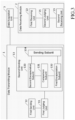
- the present invention provides a high-efficiency transmission Ethernet device, as shown in Figure 3 , comprising:
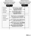
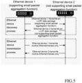
- the high-efficiency transmission Ethernet device disclosed in this technical solution also comprises two stages, as shown in Figures 4 and 5 , wherein the first stage is an Ethernet device discovery process:
- the data acquisition module 3 through a Link Layer Discovery Protocol broadcasts its own device information to the local area network where the device is located.
- the device information broadcast by the Ethernet device is configured with parameters indicating whether it supports the small packet aggregation function, each Ethernet device can obtain information indicating whether the activated Ethernet devices support the small packet aggregation function through the device information broadcast in the local area network, then an adaptive communication can be established depending on different capabilities of different Ethernet devices.
- Forms of the above-mentioned parameters are not limited, and it is only necessary to be negotiated to reach a consensus in the local area network.
- a second stage is an Ethernet device transmission process, which further comprises a data transmitting process and a data receiving process:
- the same local area network may contain both Ethernet devices supporting the small packet aggregation function and Ethernet devices not supporting the small packet aggregation function
- Ethernet devices not supporting the small packet aggregation function if aggregated Ethernet frames are sent to such Ethernet devices, data parsing may fail.
- the data packet is transmitted in the form of the routine Ethernet frames for the Ethernet devices not supporting the small packet aggregation function, while the aggregation encapsulation function of the small payload packets are enabled for the Ethernet devices supporting the small packet aggregation function, to maximize the transmission efficiency of the small payload packets.
- the second sending unit 13 comprises:
- the data packet sent by the upper-layer device at one time comprises 10 payload packets arranged in sequence, for example.
- the first payload packet is a large packet
- the second to sixth payload packets are small packets
- the seventh load packet is a large packet
- the eighth to ninth payload packets are small packets.
- the first payload packet forms a first routine Ethernet frame
- the second payload packet to the sixth payload packet are aggregately encapsulated.
- the data length of each small packet is the same, if the aggregated data length of four small packets reaches a preset maximum transmission length, only the second to fifth payload packets can be aggregately encapsulated to form the first aggregated Ethernet frame.
- the sixth payload packet is a small packet, but the seventh payload packet is a large packet, the sixth payload packet then is individually encapsulated to form a second routine Ethernet frame, the seventh payload packet is encapsulated to form a third routine Ethernet frame, the eighth payload packet to the ninth payload packet can be encapsulated to form a second aggregated Ethernet frame, then the first routine Ethernet frame, the first aggregated Ethernet frame, the second routine Ethernet frame, and the third routine Ethernet frame and the second aggregated Ethernet frame are sent to other Ethernet devices in this sequence, meaning transmission of the data packet is completed.
- the second payload packet to the fourth payload packet can be aggregately encapsulated to form the first aggregated Ethernet frame
- the fifth payload packet and the sixth payload packet are aggregately encapsulated to form the second aggregated Ethernet frame
- the seventh payload packet is encapsulated to form the third routine Ethernet frame
- the eighth payload packet to the ninth payload packet can be encapsulated to form the third aggregated Ethernet frame
- the first routine Ethernet frame, the first aggregated Ethernet frame, the second aggregated Ethernet frame, the second routine Ethernet frame, and the third aggregated Ethernet frame are sent to other Ethernet devices in this sequence, meaning transmission of the data packet is completed.
- the data receiving module 2 comprises:
- a frame structure of the routine Ethernet frames comprises a preamble, a start frame delimiter, the payload packets, a redundancy check and an interframe gap in sequence;
- a frame structure of the aggregated Ethernet frames comprises the preamble, the start frame delimiter, at least two of the payload packets, the redundancy check and the interframe gap in sequence, and each aggregated data comprises the fragment header and the payload packet.
- the start frame delimiter of the routine Ethernet frames and the start frame delimiter of the aggregated Ethernet frames have different values
- the second receiving unit determines the frame types of the data frames according to the start frame delimiter.
- definitions of the preamble, the redundancy check and the interframe gap of the routine Ethernet frame and the aggregated Ethernet frame are the same with the exception that a value of the start frame delimiter of the routine Ethernet frame is generally 0x5D, the value of the start frame delimiter of the aggregated Ethernet frame can be configured to be different from 0x5D, including but not limited to 0x5F.
- fragment header is preferably 2 bytes long, and controls the length of the payload packets of the fragment and whether the payload packet is the payload packet of the last fragment.
- the transmission efficiency of the present invention is increased by nearly 16%. Therefore, the Ethernet device of the present invention can significantly increase the Ethernet transmission efficiency of the small payload packets, and the smaller the payload packet, the higher the transmission efficiency.
Landscapes
- Engineering & Computer Science (AREA)
- Computer Networks & Wireless Communication (AREA)
- Signal Processing (AREA)
- Computer Security & Cryptography (AREA)
- Data Exchanges In Wide-Area Networks (AREA)
- Small-Scale Networks (AREA)
Abstract
Description
- The invention relates to the technical field of communication devices, and more particularly, to a high-efficiency transmission Ethernet device.
- Ethernet is a communication protocol standard that is by far the most commonly used in local area network (LAN) and it was developed in the earlier 1970s. Ethernet is a commonly used LAN standard transmitting data with a transmitting speed at 10/100/1000/2500/1000OMbps. Generally, an Ethernet device consists of a shared transmission medium, for example, a twisted-pair cable or a coaxial cable, a multiport hub, a bridge or a switch. In a star or bus configuration, the hub/switch/bridge connects computers, printers and workstations to each other with a cable.
- After the Ethernet device is started, transmission with other Ethernet devices can be roughly divided into two stages. As shown in
Figure 1 , the first stage is an Ethernet device discovery process. After startup, the Ethernet device sends its main capabilities, such as the management address, device identity and interface identity, to the other Ethernet devices connected to the same local area network through LLDP (Link layer Discovery protocol). In the meantime, the Ethernet device obtains information corresponding to the other devices in the same local area network. In the second stage, the Ethernet device sends, according to capabilities of Ethernet devices at the peer, Ethernet packets (Ethernet frames) that the Ethernet devices at the peer can process, based on the information obtained in the first stage, thereby enabling communication among different Ethernet devices. - When transmitting data over Ethernet, Ethernet data packets used in this process are called Ethernet frames. A format of each of the Ethernet frame is shown in
Figure 2 . it can be seen that the one Ethernet frame comprises a preamble, a start frame delimiter, data, a redundancy check and an interframe gap. The preamble is 7 bytes long with a default value of 7 bytes of 0x55; the start frame delimiter is 1 byte long with a default value of 0x5D; data comprises the Ethernet frame control field (having a length of 18 bytes) and an upper-layer payload data with a variable length; the redundancy check is 4 bytes long; and the interframe gap is at least 12 bytes long. The MTU (Maximum Transmission Unit) for an Ethernet is typically 1500 bytes, that is, an Ethernet data frame can be up to 1500 bytes. - In conclusion, an Ethernet data frame contains two types of data, some data is fixed overhead of some control fields; the other is an upper-layer payload data carried. The length of the upper-layer payload data is variable, while the fixed overhead of the control fields is relatively fixed, and each Ethernet frame requires a fixed overhead of at least 42 bytes. In practice, however, a large amount of short (about 100 bytes) upper-layer application data may be generated in most applications, such as data packets of voice calls, data packets of online games, and so on. If an upper-layer payload data is 100 bytes, each Ethernet frame is 142 bytes long, and the transmission efficiency is about 70.4%, relatively low.
- Given that the foregoing problems exist in the prior art, the present invention provides a high-efficiency transmission Ethernet device, comprising:
- a data transmitting module, wherein when receiving a data packet sent by an upper-layer device, and judging that other Ethernet devices in the same local area network for data transmission support a small packet aggregation function, the data transmitting module is configured to aggregately encapsulate all small packets contained in the data packet to form at least one aggregated Ethernet frame and to send it to other corresponding Ethernet devices; and
- a data receiving module, wherein when receiving data frames sent by other Ethernet devices in the same local area network supporting the small packet aggregation function, performing data parsing on the data frames according to a pre-configured conventional parsing rule when judging that the received data frames are routine Ethernet frames, and performing data parsing on the data frames according to a pre-configured aggregation parsing rule when judging the data frames are the aggregated Ethernet frames.
- Preferably, the Ethernet device further comprises a data acquisition module, wherein the data acquisition module is connected to the data transmitting module and the data receiving module, respectively, and is configured to send a broadcast about its own device information to the local area network each time when the device is powered on, and configured to acquire the device information of other Ethernet devices in the local area network, the device information comprises parameters indicating whether it supports the small packet aggregation function;
wherein the data transmitting module and the data receiving module determine whether the other Ethernet devices for data transmission support the small packet aggregation function based on the device information. - Preferably, the data acquisition module through a Link Layer Discovery Protocol broadcasts its own device information to the local area network where the device is located.
- Preferably, the data packet comprises a plurality of payload packets arranged in sequence;
the data transmitting module comprises: - a first judging unit, configured to output a first signal if it is judged that the other Ethernet devices for data transmission do not support the small packet aggregation function, and configured to output a second signal if it is judged that the other Ethernet devices support the small packet aggregation function;
- a first sending unit, connected to the first judging unit, and configured to encapsulate each of the plurality of payload packets to form the routine Ethernet frames based on the first signal and send them to the other Ethernet devices in sequence;
- a second sending unit, connected to the first judging unit, and configured to routinely encapsulate the plurality of payload packets which are large packets to form the routine Ethernet frames based on the second signal, configured to aggregately encapsulate the plurality of payload packets which are continuous small packets to form the aggregated Ethernet frames, and configured to send them sequentially to the other Ethernet devices according to an order they are arranged in the data packet.
- Preferably, the second sending unit comprises:
- a comparison subunit, configured to obtain a data length of each of the plurality of payload packets based on the second signal, and configured to configure the payload packets having the data length greater than a preset threshold as the large packets and configure the payload packets having the data length not greater than the threshold as the small packets;
- a first encapsulation subunit, connected to the comparison subunit, and configured to encapsulate the plurality of payload packets which are large packets to form the routine Ethernet frames;
- a second encapsulation subunit, connected to the comparison subunit, and configured to aggregate all of the continuous small packets and add a fragment header before each of the payload packets until the aggregated data length reaches a preset maximum transmission length or aggregation of all the continuous small packets is completed, then encapsulate the payload packets to form the aggregated Ethernet frames;
- a sending subunit, connected to the first encapsulation subunit and the second encapsulation subunit, respectively, and configured to sequentially send the routine Ethernet frames and the aggregated Ethernet frames to the other Ethernet devices according to the sequence of the plurality of payload packets in the data packet before they are encapsulated.
- Preferably, the data receiving module comprises:
- a second judging unit, configured to output a third signal if it is judged that the other Ethernet devices sending the data frames support the small packet aggregation function, and configured to output a fourth signal if it is judged that the other Ethernet devices do not support the small packet aggregation function;
- a first receiving unit, connected to the second judging unit, and configured to perform data parsing on the received data frames according to the routine parsing rule, based on the third signal; and
- a second receiving unit, connected to the second judging unit, configured to perform data parsing on the data frames according to the routine parsing rule if it is judged based on the fourth signal that frame types of the data frames are the routine Ethernet frames, and configured to perform data parsing on the data frames according to the aggregation parsing rule if it is judged based on the fourth signal that the frame types of the data frames are the aggregated Ethernet frames.
- Preferably, a frame structure of the routine Ethernet frames comprises a preamble, a start frame delimiter, the payload packets, a redundancy check and an interframe gap in sequence;
a frame structure of the aggregated Ethernet frames comprises the preamble, the start frame delimiter, at least two of the aggregated data, the redundancy check and the interframe gap in sequence, and each aggregated data comprises the fragment header and the payload packet. - Preferably, the start frame delimiter of the routine Ethernet frames and the start frame delimiter of the aggregated Ethernet frames have different values, and the second receiving unit determines the frame types of the data frames according to the start frame delimiter.
- By adopting the above-mentioned technical solutions, the present invention has the following advantages or beneficial effects: the Ethernet device is configured to have the small packet aggregation function, so that a plurality of small payload packets can be aggregately encapsulated to form an Ethernet frame during the process of transmission of the Ethernet small payload packets. In this way, the transmission rate at which the Ethernet transmits the small payload packets can be effectively improved, and the compatibility with old equipment and the Ethernet device that does not support the small packet aggregation function is guaranteed.
-
-
Figure 1 is a schematic diagram showing a process of mutual communication among existing Ethernet devices; -
Figure 2 is a frame structure of a routine Ethernet frame; -
Figure 3 is a schematic diagram showing a structure of a high-efficiency transmission Ethernet device in a preferred embodiment of the present invention; -
Figure 4 is a schematic diagram showing a process of mutual communication between two Ethernet devices supporting a small packet aggregation function in a preferred embodiment of the present invention; -
Figure 5 is a schematic diagram showing a process of mutual communication between Ethernet devices supporting a small packet aggregation function and Ethernet devices not supporting the small packet aggregation function in a preferred embodiment of the present invention; and -
Figure 6 is a frame structure of an aggregated Ethernet frame in a preferred embodiment of the present invention. - The present invention will be described hereinafter with reference to the accompanying drawings and particular embodiments, but the invention is not limited thereto. Other implementations are contemplated as long as they are consistent with the subject of the invention.
- In a preferred embodiment of the invention, given that the foregoing problems exist in the prior art, the present invention provides a high-efficiency transmission Ethernet device, as shown in
Figure 3 , comprising: - a
data transmitting module 1, wherein when receiving a data packet sent by an upper-layer device, and judging that other Ethernet devices in the same local area network for data transmission support a small packet aggregation function, thedata transmitting module 1 is configured to aggregately encapsulate all small packets contained in the data packet to form at least one aggregated Ethernet frame and to send it to other corresponding Ethernet devices; and - a
data receiving module 2, wherein when receiving data frames sent by other Ethernet devices in the same local area network supporting the small packet aggregation function, performing data parsing on the data frames according to a pre-configured routine parsing rule when judging that the received data frames are routine Ethernet frames, and performing data parsing on the data frames according to a pre-configured aggregation parsing rule when judging the data frames are aggregated Ethernet frames. - In particular, the high-efficiency transmission Ethernet device disclosed in this technical solution also comprises two stages, as shown in
Figures 4 and5 , wherein the first stage is an Ethernet device discovery process: - in a preferred embodiment of the invention, the Ethernet device further comprises a
data acquisition module 3, wherein the data acquisition module is connected to thedata transmitting module 1 and thedata receiving module 2, respectively, and is configured to send a broadcast about its own device information to the local area network each time when the device is powered on, and configured to acquire the device information of other Ethernet devices in the local area network, the device information comprises parameters indicating whether it supports the small packet aggregation function; - wherein the
data transmitting module 1 and thedata receiving module 2 determine whether the other Ethernet devices for data transmission support the small packet aggregation function based on the device information. - In a preferred embodiment of the invention, the
data acquisition module 3 through a Link Layer Discovery Protocol broadcasts its own device information to the local area network where the device is located. In this embodiment, the device information broadcast by the Ethernet device is configured with parameters indicating whether it supports the small packet aggregation function, each Ethernet device can obtain information indicating whether the activated Ethernet devices support the small packet aggregation function through the device information broadcast in the local area network, then an adaptive communication can be established depending on different capabilities of different Ethernet devices. Forms of the above-mentioned parameters are not limited, and it is only necessary to be negotiated to reach a consensus in the local area network. - A second stage is an Ethernet device transmission process, which further comprises a data transmitting process and a data receiving process:
- wherein the data transmitting process is to forward the data package sent by the upper-layer device to other Ethernet devices in the same local area network, wherein in a preferred embodiment, the data packet sent by the upper-layer device comprises a plurality of payload packets arranged in sequence;
- the
data transmitting module 1 comprises:- a
first judging unit 11, configured to output a first signal if it is judged that the other Ethernet devices for data transmission do not support the small packet aggregation function, and configured to output a second signal if it is judged that the other Ethernet devices support the small packet aggregation function; - a first sending
unit 12, connected to thefirst judging unit 11, and configured to encapsulate each of the plurality of payload packets to form the routine Ethernet frames based on the first signal and send them to the other Ethernet devices in sequence; - a
second sending unit 13, connected to thefirst judging unit 11, and configured to routinely encapsulate the plurality of payload packets which are large packets to form the routine Ethernet frames based on the second signal, configured to aggregately encapsulate the plurality of payload packets which are continuous small packets to form the aggregated Ethernet frames, and configured to send them sequentially to the other Ethernet devices according to an order they are arranged in the data packet.
- a
- In particular, considering that the same local area network may contain both Ethernet devices supporting the small packet aggregation function and Ethernet devices not supporting the small packet aggregation function, in the case of the Ethernet devices not supporting the small packet aggregation function, if aggregated Ethernet frames are sent to such Ethernet devices, data parsing may fail. In this regard, in order to ensure the compatibility of the devices, in the embodiment, the data packet is transmitted in the form of the routine Ethernet frames for the Ethernet devices not supporting the small packet aggregation function, while the aggregation encapsulation function of the small payload packets are enabled for the Ethernet devices supporting the small packet aggregation function, to maximize the transmission efficiency of the small payload packets.
- Furthermore, the second sending
unit 13 comprises: - a
comparison subunit 131, configured to obtain a data length of each of the plurality of payload packets based on the second signal, and configured to configure the payload packets having the data length greater than a preset threshold as the large packets and configure the payload packets having the data length not greater than the threshold as the small packets; - a
first encapsulation subunit 132, connected to thecomparison subunit 131, and configured to encapsulate the plurality of payload packets which are large packets to form the routine Ethernet frames; - a
second encapsulation subunit 133, connected to thecomparison subunit 131, and configured to aggregate all of the continuous small continuous packets and add a fragment header before each of the payload packets until the aggregated data length reaches a preset maximum transmission length or aggregation of all the continuous small packets is completed, then encapsulate the payload packets to form the aggregated Ethernet frames; - a sending
subunit 134, connected to thefirst encapsulation subunit 132 and thesecond encapsulation subunit 133, respectively, and configured to sequentially send the routine Ethernet frames and the aggregated Ethernet frames to the other Ethernet devices according to the sequence of the plurality of payload packets in the data packet before they are encapsulated. - In particular, in this embodiment, the data packet sent by the upper-layer device at one time comprises 10 payload packets arranged in sequence, for example. The first payload packet is a large packet, and the second to sixth payload packets are small packets, the seventh load packet is a large packet, and the eighth to ninth payload packets are small packets. In the meantime, the first payload packet forms a first routine Ethernet frame, and the second payload packet to the sixth payload packet are aggregately encapsulated. For the sake of easy explanation, it is assumed that the data length of each small packet is the same, if the aggregated data length of four small packets reaches a preset maximum transmission length, only the second to fifth payload packets can be aggregately encapsulated to form the first aggregated Ethernet frame. Although the sixth payload packet is a small packet, but the seventh payload packet is a large packet, the sixth payload packet then is individually encapsulated to form a second routine Ethernet frame,
the seventh payload packet is encapsulated to form a third routine Ethernet frame, the eighth payload packet to the ninth payload packet can be encapsulated to form a second aggregated Ethernet frame, then the first routine Ethernet frame, the first aggregated Ethernet frame, the second routine Ethernet frame, and the third routine Ethernet frame and the second aggregated Ethernet frame are sent to other Ethernet devices in this sequence, meaning transmission of the data packet is completed. - Similarly, in the above-mentioned process, if the data length of three aggregated small packets reaches the preset maximum transmission length, the second payload packet to the fourth payload packet can be aggregately encapsulated to form the first aggregated Ethernet frame, the fifth payload packet and the sixth payload packet are aggregately encapsulated to form the second aggregated Ethernet frame, the seventh payload packet is encapsulated to form the third routine Ethernet frame, and the eighth payload packet to the ninth payload packet can be encapsulated to form the third aggregated Ethernet frame, then the first routine Ethernet frame, the first aggregated Ethernet frame, the second aggregated Ethernet frame, the second routine Ethernet frame, and the third aggregated Ethernet frame are sent to other Ethernet devices in this sequence, meaning transmission of the data packet is completed.
- Wherein the above-mentioned data receiving process is a process of receiving data frames sent by the other Ethernet devices. In particular, in a preferred embodiment of the present invention, the
data receiving module 2 comprises: - a
second judging unit 21, configured to output a third signal if it is judged that the other Ethernet devices sending the data frames support the small packet aggregation function, and configured to output a fourth signal if it is judged that the other Ethernet devices do not support the small packet aggregation function; - a
first receiving unit 22, connected to thesecond judging unit 21, and configured to perform data parsing on the received data frames according to the routine parsing rule, based on the third signal; and - a
second receiving unit 23, connected to thesecond judging unit 22, configured to perform data parsing on the data frames according to the routine parsing rule if it is judged based on the fourth signal that frame types of the data frames are the routine Ethernet frames, and configured to perform data parsing on the data frames according to the aggregation parsing rule if it is judged based on the fourth signal that the frame types of the data frames are the aggregated Ethernet frames. - In particular, since different types of Ethernet data frames have different encapsulation structures, corresponding data parsing rules are also different. In this embodiment, upon receipt of data frames sent by other Ethernet devices, first determining whether the other Ethernet devices, sending the data frames, support the small packet aggregation function, if not, it means that it can only send the routine Ethernet frames, and data parsing can be done for the received data frames simply by directly invoking routine parsing rules. If the other Ethernet devices sending data support the small packet aggregation function, it can be seen from the data transmission process that they may send the routine Ethernet frames or the aggregated Ethernet frames. Therefore, it is necessary to identify the frame types before performing parsing to determine to use the routine parsing rule or the aggregated parsing rule for parsing based on the identification result that the frame types are the routine Ethernet frames or the aggregated Ethernet frames.
- In a preferred embodiment of the invention, as shown in
Figure 2 , a frame structure of the routine Ethernet frames comprises a preamble, a start frame delimiter, the payload packets, a redundancy check and an interframe gap in sequence;
as shown inFigure 6 , a frame structure of the aggregated Ethernet frames comprises the preamble, the start frame delimiter, at least two of the payload packets, the redundancy check and the interframe gap in sequence, and each aggregated data comprises the fragment header and the payload packet. - In a preferred embodiment of the invention, the start frame delimiter of the routine Ethernet frames and the start frame delimiter of the aggregated Ethernet frames have different values, and the second receiving unit determines the frame types of the data frames according to the start frame delimiter.
- In particular, in this embodiment, definitions of the preamble, the redundancy check and the interframe gap of the routine Ethernet frame and the aggregated Ethernet frame are the same with the exception that a value of the start frame delimiter of the routine Ethernet frame is generally 0x5D, the value of the start frame delimiter of the aggregated Ethernet frame can be configured to be different from 0x5D, including but not limited to 0x5F.
- Wherein the fragment header is preferably 2 bytes long, and controls the length of the payload packets of the fragment and whether the payload packet is the payload packet of the last fragment.
- As a preferred embodiment, it is assumed that continuous small load packets are present, and the data length of each small load packet is 100 bytes, and the maximum transmission length is 1500 bytes, when a high-efficiency transmission Ethernet device of the present invention is used, an aggregated Ethernet frame can transmit 1452 bytes of data, and the specific calculation formula is as follows:

- However, in the prior art, 1736 bytes are required to transmit 14 payload packets of 100 bytes, and the calculation formula is as follows:

- Its transmission efficiency is 1400/1736∗ 100=80.6%.
- In conclusion, it can be seen from this embodiment that the transmission efficiency of the present invention is increased by nearly 16%. Therefore, the Ethernet device of the present invention can significantly increase the Ethernet transmission efficiency of the small payload packets, and the smaller the payload packet, the higher the transmission efficiency.
- The above descriptions are only the preferred embodiments of the invention, not thus limiting the embodiments and scope of the invention. Those skilled in the art should be able to realize that the schemes obtained from the content of specification and drawings of the invention are within the scope of the invention.
Claims (8)
- A high-efficiency transmission Ethernet device comprises:a data transmitting module, wherein when receiving a data packet sent by an upper-layer device, and judging that other Ethernet devices in the same local area network for data transmission support a small packet aggregation function, the data transmitting module is configured to aggregately encapsulate all small packets contained in the data packet to form at least one aggregated Ethernet frame and to send it to other corresponding Ethernet devices; anda data receiving module, wherein when receiving data frames sent by other Ethernet devices in the same local area network supporting the small packet aggregation function, performing data parsing on the data frames according to a pre-configured routine parsing rule when judging that the received data frames are routine Ethernet frames, and performing data parsing on the data frames according to a pre-configured aggregation parsing rule when judging the data frames are aggregated Ethernet frames.
- The Ethernet device of claim 1, further comprising a data acquisition module, wherein the data acquisition module is connected to the data transmitting module and the data receiving module, respectively, and is configured to send a broadcast about its own device information to the local area network each time when the device is powered on, and configured to acquire the device information of other Ethernet devices in the local area network, the device information comprises parameters indicating whether it supports the small packet aggregation function;
wherein the data transmitting module and the data receiving module determine whether the other Ethernet devices for data transmission support the small packet aggregation function based on the device information. - The Ethernet device of claim 2, wherein the data acquisition module through a Link Layer Discovery Protocol broadcasts its own device information to the local area network where the device is located.
- The Ethernet device of claim 1, wherein the data packet comprises a plurality of payload packets arranged in sequence;
the data transmitting module comprises:a first judging unit, configured to output a first signal if it is judged that the other Ethernet devices for data transmission do not support the small packet aggregation function, and configured to output a second signal if it is judged that the other Ethernet devices support the small packet aggregation function;a first sending unit, connected to the first judging unit, and configured to encapsulate each of the plurality of payload packets to form the routine Ethernet frames based on the first signal and send them to the other Ethernet devices in sequence;a second sending unit, connected to the first judging unit, and configured to routinely encapsulate the plurality of payload packets which are large packets to form the routine Ethernet frames based on the second signal, configured to aggregately encapsulate the plurality of payload packets which are continuous small packets to form the aggregated Ethernet frames, and configured to send them sequentially to the other Ethernet devices according to an order they are arranged in the data packet. - The Ethernet device of claim 4, wherein the second sending unit comprises:a comparison subunit, configured to obtain a data length of each of the plurality of payload packets based on the second signal, and configured to configure the payload packets having the data length greater than a preset threshold as the large packets and configure the payload packets having the data length not greater than the threshold as the small packets;a first encapsulation subunit, connected to the comparison subunit, and configured to encapsulate the plurality of payload packets which are large packets to form the routine Ethernet frames;a second encapsulation subunit, connected to the comparison subunit, and configured to aggregate all of the continuous small packets and add a fragment header before each of the payload packets until the aggregated data length reaches a preset maximum transmission length or aggregation of all the continuous small packets is completed, then encapsulate the payload packets to form the aggregated Ethernet frame;a sending subunit, connected to the first encapsulation subunit and the second encapsulation subunit, respectively, and configured to sequentially send the routine Ethernet frames and the aggregated Ethernet frames to the other Ethernet devices according to the sequence of the plurality of payload packets in the data packet before they are encapsulated.
- The Ethernet device of claim 5, wherein the data receiving module comprises:a second judging unit, configured to output a third signal if it is judged that the other Ethernet devices sending the data frames support the small packet aggregation function, and configured to output a fourth signal if it is judged that the other Ethernet devices do not support the small packet aggregation function;a first receiving unit, connected to the second judging unit, and configured to perform data parsing on the received data frames according to the routine parsing rule, based on the third signal; anda second receiving unit, connected to the second judging unit, configured to perform data parsing on the data frames according to the routine parsing rule if it is judged based on the fourth signal that frame types of the data frames are the routine Ethernet frames, and configured to perform data parsing on the data frames according to the aggregation parsing rule if it is judged based on the fourth signal that the frame types of the data frames are the aggregated Ethernet frames.
- The Ethernet device of claim 6, wherein a frame structure of the routine Ethernet frames comprises a preamble, a start frame delimiter, the payload packets, a redundancy check and an interframe gap in sequence;
a frame structure of the aggregated Ethernet frames comprises the preamble, the start frame delimiter, at least two of the aggregated data, the redundancy check and the interframe gap in sequence, and each aggregated data comprises the fragment header and the payload packet. - The Ethernet device of claim 7, wherein the start frame delimiter of the routine Ethernet frames and the start frame delimiter of the aggregated Ethernet frames have different values, and the second receiving unit determines the frame types of the data frames according to the start frame delimiter.
Applications Claiming Priority (1)
| Application Number | Priority Date | Filing Date | Title |
|---|---|---|---|
| CN202210618516.7A CN115225711A (en) | 2022-06-01 | 2022-06-01 | An Efficient Transmission Ethernet Device |
Publications (3)
| Publication Number | Publication Date |
|---|---|
| EP4287566A1 true EP4287566A1 (en) | 2023-12-06 |
| EP4287566B1 EP4287566B1 (en) | 2025-09-17 |
| EP4287566C0 EP4287566C0 (en) | 2025-09-17 |
Family
ID=83607896
Family Applications (1)
| Application Number | Title | Priority Date | Filing Date |
|---|---|---|---|
| EP22207108.6A Active EP4287566B1 (en) | 2022-06-01 | 2022-11-14 | High-efficiency transmission ethernet device |
Country Status (7)
| Country | Link |
|---|---|
| US (1) | US11876644B2 (en) |
| EP (1) | EP4287566B1 (en) |
| JP (1) | JP7488599B2 (en) |
| KR (1) | KR102753345B1 (en) |
| CN (1) | CN115225711A (en) |
| TW (1) | TWI808035B (en) |
| WO (1) | WO2023231264A1 (en) |
Citations (3)
| Publication number | Priority date | Publication date | Assignee | Title |
|---|---|---|---|---|
| US20060072615A1 (en) * | 2004-09-29 | 2006-04-06 | Charles Narad | Packet aggregation protocol for advanced switching |
| US20200322465A1 (en) * | 2019-04-03 | 2020-10-08 | National Chiao Tung University | High-speed data-plane packet aggregation and disaggregation method |
| CN113542148A (en) * | 2021-07-15 | 2021-10-22 | 恒安嘉新(北京)科技股份公司 | Message aggregation method and device, network card and readable storage medium |
Family Cites Families (24)
| Publication number | Priority date | Publication date | Assignee | Title |
|---|---|---|---|---|
| US6721334B1 (en) * | 1999-02-18 | 2004-04-13 | 3Com Corporation | Method and apparatus for packet aggregation in packet-based network |
| US7630412B2 (en) * | 2003-08-07 | 2009-12-08 | At&T Intellectual Property I, L.P. | Methods and systems for aggregating Ethernet communications |
| US7489688B2 (en) * | 2003-12-23 | 2009-02-10 | Agere Systems Inc. | Frame aggregation |
| KR101217628B1 (en) * | 2006-02-16 | 2013-01-02 | 삼성전자주식회사 | Method for packet aggregation in power line communication network and apparatus therefor |
| CN101212390A (en) * | 2006-12-30 | 2008-07-02 | 华为技术有限公司 | A data transmission method and device |
| CN101184098B (en) * | 2007-12-11 | 2011-11-02 | 华为技术有限公司 | Data transmission method and transmission apparatus |
| US8351352B1 (en) * | 2009-07-15 | 2013-01-08 | Eastlake Iii Donald E | Methods and apparatus for RBridge hop-by-hop compression and frame aggregation |
| CN102572936B (en) * | 2010-12-29 | 2014-06-18 | 迈普通信技术股份有限公司 | Method for sending and processing wireless aggregation frame and device for sending wireless aggregation frame |
| KR20150050960A (en) * | 2013-11-01 | 2015-05-11 | (주)티에이치엔 | Method for rearranging transmission order of packet and apparatuses using the same |
| US20160099862A1 (en) * | 2014-10-01 | 2016-04-07 | Allied Telesis Holdings Kabushiki Kaisha | Redundant network formation |
| KR102073552B1 (en) * | 2014-10-31 | 2020-02-05 | 아이디 퀀티크 에스.에이. | Method and Apparatus for Generating Data Packet Requiring Encryption in Short Distance Communications |
| US12290230B2 (en) * | 2015-07-17 | 2025-05-06 | Origin Research Wireless, Inc. | Method, apparatus, and system for automatic and adaptive wireless monitoring and tracking |
| EP3424151B1 (en) * | 2016-03-03 | 2020-09-30 | Andrew Wireless Systems GmbH | Hybrid ran/digital das repeater system with ethernet transport |
| CN108965157B (en) * | 2017-05-19 | 2020-08-07 | 华为技术有限公司 | Data transmission method, device, equipment and system |
| CN109842868B (en) | 2017-11-29 | 2021-09-03 | 华为技术有限公司 | Frame aggregation and network setting frame sending method and equipment |
| US11368873B2 (en) * | 2017-12-15 | 2022-06-21 | Huawei Technologies Co., Ltd. | Method and system of packet aggregation |
| CN109861801B (en) * | 2018-10-15 | 2022-12-09 | 北京新岸线移动通信技术有限公司 | Data transmission method and device |
| US11432190B2 (en) * | 2019-01-11 | 2022-08-30 | Blackberry Limited | Aggregation of data frames |
| CN109769268B (en) * | 2019-03-19 | 2022-05-31 | 南京信息职业技术学院 | Frame aggregation algorithm |
| US11202273B2 (en) * | 2019-11-08 | 2021-12-14 | Blackberry Limited | Aggregating messages into a single transmission |
| US11329927B2 (en) * | 2020-06-30 | 2022-05-10 | Lenovo Enterprise Solutions (Singapore) Pte. Ltd. | Automatic MTU configuration on a L2 domain |
| TWI745034B (en) * | 2020-08-18 | 2021-11-01 | 國立陽明交通大學 | Method of aggregating and disaggregating packet |
| CN112601255B (en) * | 2020-12-16 | 2023-05-26 | 北京银牧微电子科技有限公司 | MAC frame transmitting method and device, PHY frame aggregation method and device |
| CN112738846A (en) * | 2020-12-25 | 2021-04-30 | 中国电子科技集团公司第五十四研究所 | A method for aggregation of Ethernet frames in wireless ad hoc networks |
-
2022
- 2022-06-01 CN CN202210618516.7A patent/CN115225711A/en active Pending
- 2022-10-09 WO PCT/CN2022/124216 patent/WO2023231264A1/en not_active Ceased
- 2022-11-04 TW TW111142280A patent/TWI808035B/en active
- 2022-11-11 US US17/985,520 patent/US11876644B2/en active Active
- 2022-11-14 EP EP22207108.6A patent/EP4287566B1/en active Active
- 2022-11-15 JP JP2022182207A patent/JP7488599B2/en active Active
- 2022-11-16 KR KR1020220153340A patent/KR102753345B1/en active Active
Patent Citations (3)
| Publication number | Priority date | Publication date | Assignee | Title |
|---|---|---|---|---|
| US20060072615A1 (en) * | 2004-09-29 | 2006-04-06 | Charles Narad | Packet aggregation protocol for advanced switching |
| US20200322465A1 (en) * | 2019-04-03 | 2020-10-08 | National Chiao Tung University | High-speed data-plane packet aggregation and disaggregation method |
| CN113542148A (en) * | 2021-07-15 | 2021-10-22 | 恒安嘉新(北京)科技股份公司 | Message aggregation method and device, network card and readable storage medium |
Also Published As
| Publication number | Publication date |
|---|---|
| CN115225711A (en) | 2022-10-21 |
| TW202349923A (en) | 2023-12-16 |
| US11876644B2 (en) | 2024-01-16 |
| JP2023177208A (en) | 2023-12-13 |
| KR102753345B1 (en) | 2025-01-09 |
| US20230396465A1 (en) | 2023-12-07 |
| JP7488599B2 (en) | 2024-05-22 |
| EP4287566B1 (en) | 2025-09-17 |
| WO2023231264A1 (en) | 2023-12-07 |
| EP4287566C0 (en) | 2025-09-17 |
| TWI808035B (en) | 2023-07-01 |
| KR20230167288A (en) | 2023-12-08 |
Similar Documents
| Publication | Publication Date | Title |
|---|---|---|
| US11477130B2 (en) | Transmission control method and apparatus | |
| US6091733A (en) | Communication device using communication protocol including transport layer and communication method using communication protocol including transport layer | |
| EP3531620B1 (en) | Method for processing message in hybrid access network, and network device | |
| EP4037267B1 (en) | Method, apparatus and system for sending message | |
| US20070291793A1 (en) | Data transmission method using packet aggregation | |
| JP2002290459A (en) | Packet transfer apparatus and method | |
| JP2009147786A (en) | Communication device, data frame transmission control method, and program | |
| US20120281541A1 (en) | Signaling Describing the Operation of a Link Bundle | |
| CN112333094A (en) | Data transmission processing method and device, network equipment and readable storage medium | |
| CN103647759A (en) | Negotiation method and apparatus of maximum segment size (MSS) | |
| CN110932992A (en) | Load balancing communication method based on tunnel mode | |
| WO2000072532A9 (en) | System and method for network packet reduction | |
| CN108282391B (en) | VXLAN message fragmentation method and device | |
| CN115766605A (en) | Network congestion control method, device and system | |
| EP2119148A1 (en) | Network offloading with reduced packet loss | |
| CN102594665B (en) | Service data transmission method and device | |
| US11876644B2 (en) | High-efficiency transmission ethernet device | |
| US6711178B1 (en) | Enhanced claw packing protocol | |
| CN113726635A (en) | Message processing method and device and electronic equipment | |
| CN107104813B (en) | Information transmission method, gateway and controller | |
| CN110912942A (en) | Method for reducing UDP message sending time delay | |
| EP2173067A1 (en) | A message processing apparatus and the method thereof | |
| CN116032862B (en) | Method for transmitting BE data by TTE system with low delay and TTE system | |
| CN118573631A (en) | Traffic congestion control method, device and system | |
| JP4434019B2 (en) | Data distribution management device and data distribution management method |
Legal Events
| Date | Code | Title | Description |
|---|---|---|---|
| PUAI | Public reference made under article 153(3) epc to a published international application that has entered the european phase |
Free format text: ORIGINAL CODE: 0009012 |
|
| STAA | Information on the status of an ep patent application or granted ep patent |
Free format text: STATUS: THE APPLICATION HAS BEEN PUBLISHED |
|
| AK | Designated contracting states |
Kind code of ref document: A1 Designated state(s): AL AT BE BG CH CY CZ DE DK EE ES FI FR GB GR HR HU IE IS IT LI LT LU LV MC ME MK MT NL NO PL PT RO RS SE SI SK SM TR |
|
| P01 | Opt-out of the competence of the unified patent court (upc) registered |
Effective date: 20231206 |
|
| STAA | Information on the status of an ep patent application or granted ep patent |
Free format text: STATUS: REQUEST FOR EXAMINATION WAS MADE |
|
| 17P | Request for examination filed |
Effective date: 20240529 |
|
| RBV | Designated contracting states (corrected) |
Designated state(s): AL AT BE BG CH CY CZ DE DK EE ES FI FR GB GR HR HU IE IS IT LI LT LU LV MC ME MK MT NL NO PL PT RO RS SE SI SK SM TR |
|
| GRAP | Despatch of communication of intention to grant a patent |
Free format text: ORIGINAL CODE: EPIDOSNIGR1 |
|
| STAA | Information on the status of an ep patent application or granted ep patent |
Free format text: STATUS: GRANT OF PATENT IS INTENDED |
|
| RIC1 | Information provided on ipc code assigned before grant |
Ipc: H04L 49/351 20220101ALN20250403BHEP Ipc: H04L 49/9057 20220101ALI20250403BHEP Ipc: H04L 47/41 20220101ALI20250403BHEP Ipc: H04L 45/00 20220101ALI20250403BHEP Ipc: H04L 12/46 20060101AFI20250403BHEP |
|
| INTG | Intention to grant announced |
Effective date: 20250416 |
|
| GRAS | Grant fee paid |
Free format text: ORIGINAL CODE: EPIDOSNIGR3 |
|
| GRAA | (expected) grant |
Free format text: ORIGINAL CODE: 0009210 |
|
| STAA | Information on the status of an ep patent application or granted ep patent |
Free format text: STATUS: THE PATENT HAS BEEN GRANTED |
|
| AK | Designated contracting states |
Kind code of ref document: B1 Designated state(s): AL AT BE BG CH CY CZ DE DK EE ES FI FR GB GR HR HU IE IS IT LI LT LU LV MC ME MK MT NL NO PL PT RO RS SE SI SK SM TR |
|
| REG | Reference to a national code |
Ref country code: GB Ref legal event code: FG4D |
|
| REG | Reference to a national code |
Ref country code: CH Ref legal event code: EP |
|
| REG | Reference to a national code |
Ref country code: IE Ref legal event code: FG4D |
|
| U01 | Request for unitary effect filed |
Effective date: 20250923 |
|
| U07 | Unitary effect registered |
Designated state(s): AT BE BG DE DK EE FI FR IT LT LU LV MT NL PT RO SE SI Effective date: 20250930 |
|
| P04 | Withdrawal of opt-out of the competence of the unified patent court (upc) registered |
Free format text: CASE NUMBER: APP_591411_1/2023 Effective date: 20250930 |
|
| U20 | Renewal fee for the european patent with unitary effect paid |
Year of fee payment: 4 Effective date: 20251112 |
|
| PG25 | Lapsed in a contracting state [announced via postgrant information from national office to epo] |
Ref country code: NO Free format text: LAPSE BECAUSE OF FAILURE TO SUBMIT A TRANSLATION OF THE DESCRIPTION OR TO PAY THE FEE WITHIN THE PRESCRIBED TIME-LIMIT Effective date: 20251217 |
|
| PG25 | Lapsed in a contracting state [announced via postgrant information from national office to epo] |
Ref country code: HR Free format text: LAPSE BECAUSE OF FAILURE TO SUBMIT A TRANSLATION OF THE DESCRIPTION OR TO PAY THE FEE WITHIN THE PRESCRIBED TIME-LIMIT Effective date: 20250917 |
|
| PG25 | Lapsed in a contracting state [announced via postgrant information from national office to epo] |
Ref country code: GR Free format text: LAPSE BECAUSE OF FAILURE TO SUBMIT A TRANSLATION OF THE DESCRIPTION OR TO PAY THE FEE WITHIN THE PRESCRIBED TIME-LIMIT Effective date: 20251218 |
|
| PG25 | Lapsed in a contracting state [announced via postgrant information from national office to epo] |
Ref country code: RS Free format text: LAPSE BECAUSE OF FAILURE TO SUBMIT A TRANSLATION OF THE DESCRIPTION OR TO PAY THE FEE WITHIN THE PRESCRIBED TIME-LIMIT Effective date: 20251217 |
|
| PG25 | Lapsed in a contracting state [announced via postgrant information from national office to epo] |
Ref country code: SM Free format text: LAPSE BECAUSE OF FAILURE TO SUBMIT A TRANSLATION OF THE DESCRIPTION OR TO PAY THE FEE WITHIN THE PRESCRIBED TIME-LIMIT Effective date: 20250917 |
|
| PG25 | Lapsed in a contracting state [announced via postgrant information from national office to epo] |
Ref country code: ES Free format text: LAPSE BECAUSE OF FAILURE TO SUBMIT A TRANSLATION OF THE DESCRIPTION OR TO PAY THE FEE WITHIN THE PRESCRIBED TIME-LIMIT Effective date: 20250917 |
|
| PG25 | Lapsed in a contracting state [announced via postgrant information from national office to epo] |
Ref country code: IS Free format text: LAPSE BECAUSE OF FAILURE TO SUBMIT A TRANSLATION OF THE DESCRIPTION OR TO PAY THE FEE WITHIN THE PRESCRIBED TIME-LIMIT Effective date: 20260117 |
|
| PG25 | Lapsed in a contracting state [announced via postgrant information from national office to epo] |
Ref country code: CZ Free format text: LAPSE BECAUSE OF FAILURE TO SUBMIT A TRANSLATION OF THE DESCRIPTION OR TO PAY THE FEE WITHIN THE PRESCRIBED TIME-LIMIT Effective date: 20250917 |
|
| PG25 | Lapsed in a contracting state [announced via postgrant information from national office to epo] |
Ref country code: PL Free format text: LAPSE BECAUSE OF FAILURE TO SUBMIT A TRANSLATION OF THE DESCRIPTION OR TO PAY THE FEE WITHIN THE PRESCRIBED TIME-LIMIT Effective date: 20250917 |
|
| PG25 | Lapsed in a contracting state [announced via postgrant information from national office to epo] |
Ref country code: SK Free format text: LAPSE BECAUSE OF FAILURE TO SUBMIT A TRANSLATION OF THE DESCRIPTION OR TO PAY THE FEE WITHIN THE PRESCRIBED TIME-LIMIT Effective date: 20250917 |