EP4287564A1 - Can interface termination control - Google Patents
Can interface termination control Download PDFInfo
- Publication number
- EP4287564A1 EP4287564A1 EP22275072.1A EP22275072A EP4287564A1 EP 4287564 A1 EP4287564 A1 EP 4287564A1 EP 22275072 A EP22275072 A EP 22275072A EP 4287564 A1 EP4287564 A1 EP 4287564A1
- Authority
- EP
- European Patent Office
- Prior art keywords
- termination
- bus
- switch
- resistor
- termination resistor
- Prior art date
- Legal status (The legal status is an assumption and is not a legal conclusion. Google has not performed a legal analysis and makes no representation as to the accuracy of the status listed.)
- Granted
Links
Images

Classifications
-
- H—ELECTRICITY
- H04—ELECTRIC COMMUNICATION TECHNIQUE
- H04L—TRANSMISSION OF DIGITAL INFORMATION, e.g. TELEGRAPHIC COMMUNICATION
- H04L12/00—Data switching networks
- H04L12/28—Data switching networks characterised by path configuration, e.g. LAN [Local Area Networks] or WAN [Wide Area Networks]
- H04L12/40—Bus networks
- H04L12/40006—Architecture of a communication node
-
- H—ELECTRICITY
- H04—ELECTRIC COMMUNICATION TECHNIQUE
- H04L—TRANSMISSION OF DIGITAL INFORMATION, e.g. TELEGRAPHIC COMMUNICATION
- H04L12/00—Data switching networks
- H04L12/28—Data switching networks characterised by path configuration, e.g. LAN [Local Area Networks] or WAN [Wide Area Networks]
- H04L12/40—Bus networks
- H04L12/40006—Architecture of a communication node
- H04L12/40032—Details regarding a bus interface enhancer
-
- H—ELECTRICITY
- H04—ELECTRIC COMMUNICATION TECHNIQUE
- H04L—TRANSMISSION OF DIGITAL INFORMATION, e.g. TELEGRAPHIC COMMUNICATION
- H04L25/00—Baseband systems
- H04L25/02—Details ; arrangements for supplying electrical power along data transmission lines
- H04L25/0264—Arrangements for coupling to transmission lines
- H04L25/0272—Arrangements for coupling to multiple lines, e.g. for differential transmission
-
- H—ELECTRICITY
- H04—ELECTRIC COMMUNICATION TECHNIQUE
- H04L—TRANSMISSION OF DIGITAL INFORMATION, e.g. TELEGRAPHIC COMMUNICATION
- H04L25/00—Baseband systems
- H04L25/02—Details ; arrangements for supplying electrical power along data transmission lines
- H04L25/0264—Arrangements for coupling to transmission lines
- H04L25/0298—Arrangement for terminating transmission lines
-
- H—ELECTRICITY
- H04—ELECTRIC COMMUNICATION TECHNIQUE
- H04L—TRANSMISSION OF DIGITAL INFORMATION, e.g. TELEGRAPHIC COMMUNICATION
- H04L12/00—Data switching networks
- H04L12/28—Data switching networks characterised by path configuration, e.g. LAN [Local Area Networks] or WAN [Wide Area Networks]
- H04L12/40—Bus networks
- H04L2012/40208—Bus networks characterized by the use of a particular bus standard
- H04L2012/40215—Controller Area Network CAN
Definitions
- the present disclosure is concerned with controlling termination resistance in a CAN interface.
- a controller area network is an electronic bus designed to connect various devices, e.g. ECUs, (also known as nodes) together and to send messages containing information such as sensor parameters, commands etc. between the nodes.
- ECUs also known as nodes
- Typical devices that are connected to a CAN bus are sensors, actuators and other control devices.
- the CAN bus consists of two wires and allows all connected devices/nodes to communicate with and via the bus.
- CAN buses are used, e.g. in automotives and in aerospace to connect and allow communication between various ECUs or devices in the vehicle/aircraft.
- the CAN is particularly suitable in high electrical noise environments as it is designed to work with high noise immunity.
- the bus has two ends connected to nodes or interfaces but is also connected to other so-called stub devices or nodes between the ends of the bus.
- the bus is, as mentioned above, formed of a wire pair and generally has a 120 Ohm characteristic impedance. Termination resistors, usually 120 Ohms, are provided at the nodes at the ends of the bus, to suppress reflections back along the bus, but the stub devices do not need such resistors.
- the CAN termination resistor can be split into two series resistors (typically each 60 Ohms) with the mid-point between the resistors connected via a capacitor to ground (or the vehicle chassis). This provides a capacitive coupling path for any high frequency noise on the bus.
- a controller area network, CAN, device arranged to communicate on a CAN bus
- the device comprising a processor, a CAN controller, a CAN transceiver and a termination resistor and switch assembly, the termination resistor and switch assembly comprising a switch and a first termination resistor and a second termination resistor for connection, respectively, between the device and a first line and a second line of the CAN bus, the switch comprising a dual opto-coupled solid-state relay, between the first termination resistor and the second termination resistor, and a split termination capacitor connected at a mid-point between the first termination resistor and the second termination resistor and ground, whereby the switch is controlled by a termination enable signal from the device processor to switch in or switch out the first and second termination resistors according to a position of the device on the CAN bus.
- controller area network with a plurality of such devices, as well as a method of adjusting the termination resistance of a CAN device.
- a CAN bus is a two wire bus to which several devices or nodes are connected for communication on and via the bus.
- the nodes connected to the bus transmit and receive information sent as binary information using a frame according to a selected CAN communication protocol as is known in the art and this will not be described further here.
- Each node is provided with a central processor unit, usually a microprocessor (here abbreviated to MCU), a CAN controller for controlling reception and transmission of data from and to the bus, and a CAN transceiver.
- a central processor unit usually a microprocessor (here abbreviated to MCU), a CAN controller for controlling reception and transmission of data from and to the bus, and a CAN transceiver.
- nodes For those nodes to be provided to the ends of the bus, it is necessary to provide the node with a termination resistor. Nodes connected to the CAN bus between its ends do not have a termination resistor.
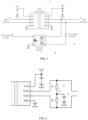
- Figure 1 shows the standard method of CAN termination of an isolated CAN transceiver 1 connected to the MCU of the node at the MCU interface 2 and to the CAN bus at the CAN interface 3.
- the transceiver drives data to and detects data from the CAN bus.
- the node is also provided with a switchable solid state relay 4 that allows a termination resistor 5 to be switched in (for an end node) or not (for a stub node). If the termination resistor 5 is to be activated or enabled for a given node, a termination enable signal 6 is provided to the isolated switch 4.
- the switch closes to connect the termination resistor 5 across the CAN interface 3 thus providing termination resistance for that node. This works well for a single termination resistor, using e.g. a MOSFET that switches the resistor in or out.
- the termination resistor 5' is split into two resistors 5a, 5b connected across the high and low bus lines between the CAN interface and the transceiver.
- the mid-point M between the two split resistors 5a, 5b is connected to ground via a capacitor 6.
- the filter capacitor 6 value is preferably selected to create a 3dB point above the CAN bus bitrate.
- the present disclosure provides a method of software control for switching in a split CAN termination so that any one node can be easily and quickly configured to be an end node or a stub node without a change in hardware and typically requiring only software or firmware changes.
- An example of this is described with reference to Fig. 3 which shows a CAN transceiver 10 connected, as in the example described above, between an MCU interface 20 and a CAN interface 30.
- An isolated switch 40 with solid state circuitry is provided for the node to control the enabling of two split termination resistors 50a, 50b for respective connection to the high and low bus wires 31, 32.
- the switch 40 comprises two solid state devices 40a, 40b forming a dual opto-coupled solid state relay (SSR).
- SSR solid state relay
- a dual opto-coupled SSR is advantageous in that it provides isolation, but other types of isolation could be used.
- the first solid state device 40a is connected between a first side of the first split resistor 50a and ground, via a capacitor 60.
- the second solid state device 40b is connected with a first side of the second split resistor 50b and ground via the capacitor 60.
- the opto-coupler LEDs 41a, 41b are connected in series between a termination enable line 70 (here, e.g. via an impedance) and ground.
- the first LED 41a activates the first solid state device to enable the first resistor and the second LED 41b activates the second solid state device to enable the second resistor.
- the other sides of the resistors are connected, respectively, to the high and low lines 31, 32.
- the isolated switch 60 will now be described in more detail.
- the termination resistors 50a, 50b values are selected to take into account the on-resistance of the solid state relay 40a, 40b.
- the enable signal provided to the switch can be either high side control or low side control depending on the MCU sink/source current capability.
- the opto-coupler LEDs 41a, 41b to activate the SSR 40a, 40b are series connected and can be controlled directly from the MCU.
- a single part can be used for the transceiver regardless of whether the node will be an end node or a stub node.
- a new node is added, a previous end node may then become a stub node and the termination resistor can be disabled.
- the enabling/disabling of termination can be automated by the software in the CAN devices, so that a negotiation is carried out to detect all CAN devices, and if any new devices are detected or previous devices are missing, the required termination settings are automatically applied.
- the control mechanism provides an electrically isolated way of controlling CAN termination with a split termination capacitor.
- the termination according to the disclosure can be controlled directly by the node MCU which means that the node can be easily and quickly adapted to be an end node or a stub node.
Landscapes
- Engineering & Computer Science (AREA)
- Computer Networks & Wireless Communication (AREA)
- Signal Processing (AREA)
- Power Engineering (AREA)
- Small-Scale Networks (AREA)
- Dc Digital Transmission (AREA)
Abstract
Description
- The present disclosure is concerned with controlling termination resistance in a CAN interface.
- A controller area network (CAN) is an electronic bus designed to connect various devices, e.g. ECUs, (also known as nodes) together and to send messages containing information such as sensor parameters, commands etc. between the nodes. Typical devices that are connected to a CAN bus are sensors, actuators and other control devices. The CAN bus consists of two wires and allows all connected devices/nodes to communicate with and via the bus. CAN buses are used, e.g. in automotives and in aerospace to connect and allow communication between various ECUs or devices in the vehicle/aircraft. The CAN is particularly suitable in high electrical noise environments as it is designed to work with high noise immunity. The bus has two ends connected to nodes or interfaces but is also connected to other so-called stub devices or nodes between the ends of the bus. The bus is, as mentioned above, formed of a wire pair and generally has a 120 Ohm characteristic impedance. Termination resistors, usually 120 Ohms, are provided at the nodes at the ends of the bus, to suppress reflections back along the bus, but the stub devices do not need such resistors. For improved EMI emission levels, the CAN termination resistor can be split into two series resistors (typically each 60 Ohms) with the mid-point between the resistors connected via a capacitor to ground (or the vehicle chassis). This provides a capacitive coupling path for any high frequency noise on the bus. When providing nodes to be attached to the bus, it is often not known whether the node will be provided at the end of the bus or as a stub device between the bus ends and, therefore, not known whether the node is one that will require a termination resistor.
- To simplify the design process, it has been considered by the inventors to be desirable to be able to control termination resistance for a node according to its intended location on the bus.
- According to the disclosure there is provided a controller area network, CAN, device arranged to communicate on a CAN bus, the device comprising a processor, a CAN controller, a CAN transceiver and a termination resistor and switch assembly, the termination resistor and switch assembly comprising a switch and a first termination resistor and a second termination resistor for connection, respectively, between the device and a first line and a second line of the CAN bus, the switch comprising a dual opto-coupled solid-state relay, between the first termination resistor and the second termination resistor, and a split termination capacitor connected at a mid-point between the first termination resistor and the second termination resistor and ground, whereby the switch is controlled by a termination enable signal from the device processor to switch in or switch out the first and second termination resistors according to a position of the device on the CAN bus.
- Also provided is a controller area network with a plurality of such devices, as well as a method of adjusting the termination resistance of a CAN device.
- Examples of the termination control according to the disclosure will now be described. It should be noted that variations are possible within the scope of the claims.
-
Figure 1 is a simple circuit diagram showing standard CAN termination of an isolated CAN transceiver. -
Figure 2 shows an example of split CAN termination -
Figure 3 is a simple circuit diagram showing control of the CAN termination according to an example of the disclosure. - As mentioned above, a CAN bus is a two wire bus to which several devices or nodes are connected for communication on and via the bus. The nodes connected to the bus transmit and receive information sent as binary information using a frame according to a selected CAN communication protocol as is known in the art and this will not be described further here.
- Each node is provided with a central processor unit, usually a microprocessor (here abbreviated to MCU), a CAN controller for controlling reception and transmission of data from and to the bus, and a CAN transceiver.
- For those nodes to be provided to the ends of the bus, it is necessary to provide the node with a termination resistor. Nodes connected to the CAN bus between its ends do not have a termination resistor.
-
Figure 1 shows the standard method of CAN termination of anisolated CAN transceiver 1 connected to the MCU of the node at theMCU interface 2 and to the CAN bus at theCAN interface 3. The transceiver drives data to and detects data from the CAN bus. The node is also provided with a switchablesolid state relay 4 that allows atermination resistor 5 to be switched in (for an end node) or not (for a stub node). If thetermination resistor 5 is to be activated or enabled for a given node, a termination enablesignal 6 is provided to theisolated switch 4. The switch closes to connect thetermination resistor 5 across theCAN interface 3 thus providing termination resistance for that node. This works well for a single termination resistor, using e.g. a MOSFET that switches the resistor in or out. - In the case of the termination resistor being a split resistor, as shown in
Fig. 2 , the switching in or out is, however, not so simple. The termination resistor 5' is split into tworesistors split resistors capacitor 6. Thefilter capacitor 6 value is preferably selected to create a 3dB point above the CAN bus bitrate. - The present disclosure provides a method of software control for switching in a split CAN termination so that any one node can be easily and quickly configured to be an end node or a stub node without a change in hardware and typically requiring only software or firmware changes. An example of this is described with reference to
Fig. 3 which shows aCAN transceiver 10 connected, as in the example described above, between anMCU interface 20 and aCAN interface 30. - An
isolated switch 40 with solid state circuitry is provided for the node to control the enabling of twosplit termination resistors low bus wires switch 40 comprises twosolid state devices solid state device 40a is connected between a first side of thefirst split resistor 50a and ground, via acapacitor 60. The secondsolid state device 40b is connected with a first side of thesecond split resistor 50b and ground via thecapacitor 60. - The opto-
coupler LEDs first LED 41a activates the first solid state device to enable the first resistor and thesecond LED 41b activates the second solid state device to enable the second resistor. The other sides of the resistors are connected, respectively, to the high andlow lines - The series common mode output choke and the
parallel termination resistors capacitor 60 together also form a noise filter 80. - The
isolated switch 60 will now be described in more detail. - The
termination resistors solid state relay coupler LEDs - By having a software controlled switching in and out of the split termination resistor, a single part can be used for the transceiver regardless of whether the node will be an end node or a stub node. In a network with many nodes, there may be a need to remove one node that was, for example, previously an end node, which means that a different node, that was previously a stub node with no termination resistor, can easily be configured with a termination resistor when it becomes a new end node. Similarly, if a new node is added, a previous end node may then become a stub node and the termination resistor can be disabled. The enabling/disabling of termination can be automated by the software in the CAN devices, so that a negotiation is carried out to detect all CAN devices, and if any new devices are detected or previous devices are missing, the required termination settings are automatically applied.
- The control mechanism provides an electrically isolated way of controlling CAN termination with a split termination capacitor. The termination according to the disclosure can be controlled directly by the node MCU which means that the node can be easily and quickly adapted to be an end node or a stub node. These advantages are provided using a small number of inexpensive components and the circuitry has a small pcb footprint.
Claims (12)
- A controller area network, CAN, device arranged to communicate on a CAN bus, the device comprising a processor, a CAN controller, a CAN transceiver (10) and a termination resistor and switch assembly, the termination resistor and switch assembly comprising a switch (40) and a first termination resistor (50a) and a second termination resistor (50b) for connection, respectively, between the device and a first line (31) and a second line (32) of the CAN bus, the switch comprising a dual opto-coupled solid-state relay, between the first termination resistor and the second termination resistor, and a split termination capacitor (60) connected at a mid-point between the first termination resistor and the second termination resistor and ground, whereby the switch is controlled by a termination enable signal from the device processor to switch in or switch out the first and second termination resistors according to a position of the device on the CAN bus.
- The CAN device of claim 1, wherein the dual opto-coupled solid-state relay comprises a first opto-coupler LED (41a) and a first solid state device (4oa) arranged to be enabled by the first opto-coupler LED and a second opto-coupler LED (41b) and a second solid state device (40b) arranged to be enabled by the second opto-coupler LED, first and second solid-state devices connected in series and the split termination capacitor connected from the mid-point between the first and second solid-state devices and ground.
- The CAN device of claim 2, wherein the first solid-state device (40a) is connected between a first side of the first split resistor (50a) and ground, and the second solid-state device (40b) is connected with a first side of the second split resistor (50b) and ground via the split termination capacitor (60).
- The CAN device of claim 2 or 3, wherein the first and second opto-coupler LEDs are connected in series between a termination enable line (70) connected to the processor, and ground.
- The CAN device of any preceding claim, wherein the first and second termination resistors and the slit termination capacitor combine to form a noise filter.
- The CAN device of any preceding claim, wherein the termination enable signal is controlled by software stored in the processor.
- The CAN device of any preceding claim, wherein the software stored in the processor is configured to control the termination enable signal based on a detection of all devices connected to the CAN.
- A control area network, CAN, comprising a CAN bus and a plurality of CAN devices as claimed in any preceding claim for connection to and communication with and over the CAN bus, wherein the enable signal is controlled for each device according to its intended location of the bus.
- The CAN of claim 8, wherein the processor is a microprocessor and the transceiver being connected to the microprocessor via an interface.
- A method of controlling the termination resistance of a CAN device for connection to a bus of a CAN, the method comprising generating an enable signal to switch on or off a split termination resistor for the device depending on the position of the device on the CAN bus.
- The method of claim 10, further comprising detecting the position of other devices on the CAN bus and controlling the enable signal for each device depending on the detected positions of other devices on the bus.
- The method of claim 10 or 11, further comprising adjusting the termination resistance for a device in response to the device changing between a position at an end of the bus and a position intermediate the ends of the bus.
Priority Applications (2)
| Application Number | Priority Date | Filing Date | Title |
|---|---|---|---|
| EP22275072.1A EP4287564B1 (en) | 2022-06-02 | 2022-06-02 | Can interface termination control |
| US18/204,667 US20230396462A1 (en) | 2022-06-02 | 2023-06-01 | Can interface termination control |
Applications Claiming Priority (1)
| Application Number | Priority Date | Filing Date | Title |
|---|---|---|---|
| EP22275072.1A EP4287564B1 (en) | 2022-06-02 | 2022-06-02 | Can interface termination control |
Publications (2)
| Publication Number | Publication Date |
|---|---|
| EP4287564A1 true EP4287564A1 (en) | 2023-12-06 |
| EP4287564B1 EP4287564B1 (en) | 2026-04-08 |
Family
ID=81940576
Family Applications (1)
| Application Number | Title | Priority Date | Filing Date |
|---|---|---|---|
| EP22275072.1A Active EP4287564B1 (en) | 2022-06-02 | 2022-06-02 | Can interface termination control |
Country Status (2)
| Country | Link |
|---|---|
| US (1) | US20230396462A1 (en) |
| EP (1) | EP4287564B1 (en) |
Families Citing this family (1)
| Publication number | Priority date | Publication date | Assignee | Title |
|---|---|---|---|---|
| KR20250005730A (en) * | 2023-07-03 | 2025-01-10 | 삼성에스디아이 주식회사 | Can communication apparatus and method |
Citations (3)
| Publication number | Priority date | Publication date | Assignee | Title |
|---|---|---|---|---|
| US20150346259A1 (en) * | 2014-05-27 | 2015-12-03 | GM Global Technology Operations LLC | Method and apparatus for open-wire fault detection and diagnosis in a controller area network |
| EP3214803A1 (en) * | 2016-03-03 | 2017-09-06 | Nxp B.V. | Feedforward ringing suppression circuit |
| US20190018817A1 (en) * | 2016-04-04 | 2019-01-17 | A-Dec, Inc. | High speed communications network in dental equipment |
Family Cites Families (8)
| Publication number | Priority date | Publication date | Assignee | Title |
|---|---|---|---|---|
| US6889345B2 (en) * | 2001-10-19 | 2005-05-03 | Hewlett-Packard Development Company, Lp. | System and method for locating a failed storage device in a data storage system |
| DE102015121732B4 (en) * | 2015-12-14 | 2022-07-14 | Knorr-Bremse Systeme für Nutzfahrzeuge GmbH | Circuit arrangement for a switchable line termination of a serial bus |
| US20190098723A1 (en) * | 2017-09-28 | 2019-03-28 | Innosys, Inc. | High Capacity Flexible Lighting Fixture, System and Method |
| US11057213B2 (en) * | 2017-10-13 | 2021-07-06 | Garrett Transportation I, Inc. | Authentication system for electronic control unit on a bus |
| US11804679B2 (en) * | 2018-09-07 | 2023-10-31 | Cilag Gmbh International | Flexible hand-switch circuit |
| US11373831B2 (en) * | 2019-05-18 | 2022-06-28 | Amber Solutions, Inc. | Intelligent circuit breakers |
| US10785066B1 (en) * | 2019-11-22 | 2020-09-22 | Nxp B.V. | Can communication with broken cable |
| US11539548B2 (en) * | 2020-09-23 | 2022-12-27 | Microchip Technology Incorporated | Method, system and apparatus for suppressing controller area network bus ringing |
-
2022
- 2022-06-02 EP EP22275072.1A patent/EP4287564B1/en active Active
-
2023
- 2023-06-01 US US18/204,667 patent/US20230396462A1/en not_active Abandoned
Patent Citations (3)
| Publication number | Priority date | Publication date | Assignee | Title |
|---|---|---|---|---|
| US20150346259A1 (en) * | 2014-05-27 | 2015-12-03 | GM Global Technology Operations LLC | Method and apparatus for open-wire fault detection and diagnosis in a controller area network |
| EP3214803A1 (en) * | 2016-03-03 | 2017-09-06 | Nxp B.V. | Feedforward ringing suppression circuit |
| US20190018817A1 (en) * | 2016-04-04 | 2019-01-17 | A-Dec, Inc. | High speed communications network in dental equipment |
Also Published As
| Publication number | Publication date |
|---|---|
| EP4287564B1 (en) | 2026-04-08 |
| US20230396462A1 (en) | 2023-12-07 |
Similar Documents
| Publication | Publication Date | Title |
|---|---|---|
| KR101922797B1 (en) | Feedforward ringing suppression circuit | |
| JP2851124B2 (en) | Multiplex transmission method | |
| EP2726997B1 (en) | Broadcast serial bus termination | |
| CA2528392A1 (en) | Multi-functional port | |
| KR20030030012A (en) | System and method for transmission-line termination by signal cancellation, and applications thereof | |
| US20180262595A1 (en) | Interfaces for selecting among multiple communications protocols | |
| KR20200033341A (en) | Transceiver for bus system, and method for reducing vibration tendency when switching between different bit states | |
| US20230396462A1 (en) | Can interface termination control | |
| JP2022553574A5 (en) | ||
| CN111711552A (en) | Terminal resistor access circuit, servo driver and control system | |
| AU2347792A (en) | Automatic detector and selector of rs-232 or v.35 interface | |
| US11190372B2 (en) | Differential bus network | |
| CN102693117B (en) | Interface circuit and electronic device with interface circuit | |
| CN104852871B (en) | RS-485 network-based resistor configuration system and method thereof | |
| US10880115B2 (en) | Method for performing a data communication | |
| KR20200033340A (en) | Transceiver for bus system, and method for reducing vibration tendency when switching between different bit states | |
| US7752503B2 (en) | CAN controller system | |
| CN111164937B (en) | Transmitting/receiving device for a bus system and method for reducing the tendency of oscillations during transitions between different bit states | |
| US10187229B2 (en) | Bi-directional, full-duplex differential communication over a single conductor pair | |
| JP2002140139A (en) | Method and device for electrically terminating transmission bus for communication network | |
| JPH0370423B2 (en) | ||
| JP2022141060A (en) | Communication system for gas engine-driven air conditioner | |
| US20240291127A1 (en) | Bus interface for a two-wire bus with adjustable pull-up/pull-down resistance values | |
| CN117478124A (en) | Bidirectional digital isolator and communication method | |
| CN120277013A (en) | Electronic device and signal transmission control method |
Legal Events
| Date | Code | Title | Description |
|---|---|---|---|
| PUAI | Public reference made under article 153(3) epc to a published international application that has entered the european phase |
Free format text: ORIGINAL CODE: 0009012 |
|
| STAA | Information on the status of an ep patent application or granted ep patent |
Free format text: STATUS: THE APPLICATION HAS BEEN PUBLISHED |
|
| AK | Designated contracting states |
Kind code of ref document: A1 Designated state(s): AL AT BE BG CH CY CZ DE DK EE ES FI FR GB GR HR HU IE IS IT LI LT LU LV MC MK MT NL NO PL PT RO RS SE SI SK SM TR |
|
| STAA | Information on the status of an ep patent application or granted ep patent |
Free format text: STATUS: REQUEST FOR EXAMINATION WAS MADE |
|
| 17P | Request for examination filed |
Effective date: 20240605 |
|
| RBV | Designated contracting states (corrected) |
Designated state(s): AL AT BE BG CH CY CZ DE DK EE ES FI FR GB GR HR HU IE IS IT LI LT LU LV MC MK MT NL NO PL PT RO RS SE SI SK SM TR |
|
| GRAP | Despatch of communication of intention to grant a patent |
Free format text: ORIGINAL CODE: EPIDOSNIGR1 |
|
| STAA | Information on the status of an ep patent application or granted ep patent |
Free format text: STATUS: GRANT OF PATENT IS INTENDED |
|
| INTG | Intention to grant announced |
Effective date: 20251208 |
|
| RIC1 | Information provided on ipc code assigned before grant |
Ipc: H04L 12/40 20060101AFI20251128BHEP Ipc: H04L 25/02 20060101ALI20251128BHEP |
|
| GRAS | Grant fee paid |
Free format text: ORIGINAL CODE: EPIDOSNIGR3 |
|
| GRAA | (expected) grant |
Free format text: ORIGINAL CODE: 0009210 |
|
| STAA | Information on the status of an ep patent application or granted ep patent |
Free format text: STATUS: THE PATENT HAS BEEN GRANTED |
|
| AK | Designated contracting states |
Kind code of ref document: B1 Designated state(s): AL AT BE BG CH CY CZ DE DK EE ES FI FR GB GR HR HU IE IS IT LI LT LU LV MC MK MT NL NO PL PT RO RS SE SI SK SM TR |
|
| REG | Reference to a national code |
Ref country code: CH Ref legal event code: F10 Free format text: ST27 STATUS EVENT CODE: U-0-0-F10-F00 (AS PROVIDED BY THE NATIONAL OFFICE) Effective date: 20260408 Ref country code: GB Ref legal event code: FG4D |
|
| REG | Reference to a national code |
Ref country code: DE Ref legal event code: R096 Ref document number: 602022033956 Country of ref document: DE |