EP4287374A1 - Battery pack and vehicle comprising same - Google Patents
Battery pack and vehicle comprising same Download PDFInfo
- Publication number
- EP4287374A1 EP4287374A1 EP22895850.0A EP22895850A EP4287374A1 EP 4287374 A1 EP4287374 A1 EP 4287374A1 EP 22895850 A EP22895850 A EP 22895850A EP 4287374 A1 EP4287374 A1 EP 4287374A1
- Authority
- EP
- European Patent Office
- Prior art keywords
- bushing
- gasket
- battery pack
- tray
- pack according
- Prior art date
- Legal status (The legal status is an assumption and is not a legal conclusion. Google has not performed a legal analysis and makes no representation as to the accuracy of the status listed.)
- Pending
Links
Images



Classifications
-
- H—ELECTRICITY
- H01—ELECTRIC ELEMENTS
- H01M—PROCESSES OR MEANS, e.g. BATTERIES, FOR THE DIRECT CONVERSION OF CHEMICAL ENERGY INTO ELECTRICAL ENERGY
- H01M50/00—Constructional details or processes of manufacture of the non-active parts of electrochemical cells other than fuel cells, e.g. hybrid cells
- H01M50/10—Primary casings; Jackets or wrappings
- H01M50/183—Sealing members
- H01M50/186—Sealing members characterised by the disposition of the sealing members
-
- H—ELECTRICITY
- H01—ELECTRIC ELEMENTS
- H01M—PROCESSES OR MEANS, e.g. BATTERIES, FOR THE DIRECT CONVERSION OF CHEMICAL ENERGY INTO ELECTRICAL ENERGY
- H01M50/00—Constructional details or processes of manufacture of the non-active parts of electrochemical cells other than fuel cells, e.g. hybrid cells
- H01M50/20—Mountings; Secondary casings or frames; Racks, modules or packs; Suspension devices; Shock absorbers; Transport or carrying devices; Holders
- H01M50/204—Racks, modules or packs for multiple batteries or multiple cells
-
- H—ELECTRICITY
- H01—ELECTRIC ELEMENTS
- H01M—PROCESSES OR MEANS, e.g. BATTERIES, FOR THE DIRECT CONVERSION OF CHEMICAL ENERGY INTO ELECTRICAL ENERGY
- H01M50/00—Constructional details or processes of manufacture of the non-active parts of electrochemical cells other than fuel cells, e.g. hybrid cells
- H01M50/20—Mountings; Secondary casings or frames; Racks, modules or packs; Suspension devices; Shock absorbers; Transport or carrying devices; Holders
- H01M50/204—Racks, modules or packs for multiple batteries or multiple cells
- H01M50/207—Racks, modules or packs for multiple batteries or multiple cells characterised by their shape
- H01M50/209—Racks, modules or packs for multiple batteries or multiple cells characterised by their shape adapted for prismatic or rectangular cells
-
- H—ELECTRICITY
- H01—ELECTRIC ELEMENTS
- H01M—PROCESSES OR MEANS, e.g. BATTERIES, FOR THE DIRECT CONVERSION OF CHEMICAL ENERGY INTO ELECTRICAL ENERGY
- H01M50/00—Constructional details or processes of manufacture of the non-active parts of electrochemical cells other than fuel cells, e.g. hybrid cells
- H01M50/20—Mountings; Secondary casings or frames; Racks, modules or packs; Suspension devices; Shock absorbers; Transport or carrying devices; Holders
- H01M50/244—Secondary casings; Racks; Suspension devices; Carrying devices; Holders characterised by their mounting method
-
- H—ELECTRICITY
- H01—ELECTRIC ELEMENTS
- H01M—PROCESSES OR MEANS, e.g. BATTERIES, FOR THE DIRECT CONVERSION OF CHEMICAL ENERGY INTO ELECTRICAL ENERGY
- H01M50/00—Constructional details or processes of manufacture of the non-active parts of electrochemical cells other than fuel cells, e.g. hybrid cells
- H01M50/20—Mountings; Secondary casings or frames; Racks, modules or packs; Suspension devices; Shock absorbers; Transport or carrying devices; Holders
- H01M50/249—Mountings; Secondary casings or frames; Racks, modules or packs; Suspension devices; Shock absorbers; Transport or carrying devices; Holders specially adapted for aircraft or vehicles, e.g. cars or trains
-
- H—ELECTRICITY
- H01—ELECTRIC ELEMENTS
- H01M—PROCESSES OR MEANS, e.g. BATTERIES, FOR THE DIRECT CONVERSION OF CHEMICAL ENERGY INTO ELECTRICAL ENERGY
- H01M50/00—Constructional details or processes of manufacture of the non-active parts of electrochemical cells other than fuel cells, e.g. hybrid cells
- H01M50/20—Mountings; Secondary casings or frames; Racks, modules or packs; Suspension devices; Shock absorbers; Transport or carrying devices; Holders
- H01M50/262—Mountings; Secondary casings or frames; Racks, modules or packs; Suspension devices; Shock absorbers; Transport or carrying devices; Holders with fastening means, e.g. locks
-
- H—ELECTRICITY
- H01—ELECTRIC ELEMENTS
- H01M—PROCESSES OR MEANS, e.g. BATTERIES, FOR THE DIRECT CONVERSION OF CHEMICAL ENERGY INTO ELECTRICAL ENERGY
- H01M50/00—Constructional details or processes of manufacture of the non-active parts of electrochemical cells other than fuel cells, e.g. hybrid cells
- H01M50/20—Mountings; Secondary casings or frames; Racks, modules or packs; Suspension devices; Shock absorbers; Transport or carrying devices; Holders
- H01M50/271—Lids or covers for the racks or secondary casings
-
- H—ELECTRICITY
- H01—ELECTRIC ELEMENTS
- H01M—PROCESSES OR MEANS, e.g. BATTERIES, FOR THE DIRECT CONVERSION OF CHEMICAL ENERGY INTO ELECTRICAL ENERGY
- H01M2220/00—Batteries for particular applications
- H01M2220/20—Batteries in motive systems, e.g. vehicle, ship, plane
-
- Y—GENERAL TAGGING OF NEW TECHNOLOGICAL DEVELOPMENTS; GENERAL TAGGING OF CROSS-SECTIONAL TECHNOLOGIES SPANNING OVER SEVERAL SECTIONS OF THE IPC; TECHNICAL SUBJECTS COVERED BY FORMER USPC CROSS-REFERENCE ART COLLECTIONS [XRACs] AND DIGESTS
- Y02—TECHNOLOGIES OR APPLICATIONS FOR MITIGATION OR ADAPTATION AGAINST CLIMATE CHANGE
- Y02E—REDUCTION OF GREENHOUSE GAS [GHG] EMISSIONS, RELATED TO ENERGY GENERATION, TRANSMISSION OR DISTRIBUTION
- Y02E60/00—Enabling technologies; Technologies with a potential or indirect contribution to GHG emissions mitigation
- Y02E60/10—Energy storage using batteries
Definitions
- the present disclosure relates to a battery pack and a vehicle including the same.
- Secondary batteries have high applicability according to product groups and electrical characteristics such as high energy density, and thus, are commonly applied not only to mobile devices but also to electric vehicles (EVs) or hybrid vehicles (HEVs) driven by electric power sources. Because secondary batteries may radically reduce the use of fossil fuel and do not generate any by-products that come with energy consumption, the secondary batteries are gaining attention as a new alternative energy source for improving eco-friendliness and energy efficiency.
- EVs electric vehicles
- HEVs hybrid vehicles
- Types of secondary batteries that are currently widely used include lithium-ion batteries, lithium polymer batteries, nickel cadmium batteries, nickel hydride batteries, and nickel zinc batteries.
- An operating voltage of a unit secondary battery cell ranges from about 2.5 V to about 4.5 V. Accordingly, when a higher output voltage is required, a battery pack may be configured by connecting a plurality of battery cells in series. Also, a battery pack may be configured by connecting a plurality of battery cells in parallel according to charge/discharge capacity required for the battery pack. Accordingly, the number of battery cells included in a battery pack may be set in various ways according to a required output voltage or charge/discharge capacity.
- a method of first configuring a battery module including at least one battery cell and adding other elements by using the at least one battery module to configure a battery pack is general.
- a conventional battery pack generally includes at least one battery module including at least one battery cell, a case tray supporting the at least one battery module, and a tray cover coupled to the case tray.
- a sealing gasket is assembled with the case tray and the tray cover.
- a separate gasket mounting structure such as a flange or a groove for seating the sealing gasket on the case tray or tray cover is additionally made to assemble the sealing gasket.
- the present disclosure is designed to solve the problems of the related art, and therefore the present disclosure is directed to providing a battery pack capable of increasing energy density and securing sealing performance, and a vehicle including the battery pack.
- Another object of the present disclosure is to provide a battery pack capable of securing cost competitiveness and a vehicle including the battery pack.
- a battery pack comprising: at least one battery module including at least one battery cell; a case tray configured to support the at least one battery module; a tray cover coupled to the case tray; and at least one bushing gasket configured to connect the case tray and the tray cover and to support the case tray on at least three points.
- the bushing gasket may include: a gasket member configured to support the case tray; a bushing member inserted into the gasket member; a bolting member disposed on one side of the gasket member; and a nut member fastened with the bolting member and configured to pass through the bushing member on the other side of the gasket member.
- the gasket member may include: a gasket body provided with a bushing member insert hole into which the bushing member is inserted; and at least one guide pin provided on the gasket body.
- the at least one guide pin may be formed to protrude from the other side of the gasket body to a predetermined length.
- the guide pin may be provided as a pair, and the pair of guide pins may be disposed with the bushing member insert hole interposed therebetween.
- the gasket member may include a gasket bead provided on the gasket body and provided along the circumference of the bushing member insert hole.
- the bushing member may include: a bushing body inserted into the bushing member insert hole; and a bushing opening formed in the bushing body configured to allow the nut member to pass therethrough.
- the tray cover may be provided with a nut member insert hole through which the nut member passes.
- the bushing gasket may be provided in plurality, and the plurality of bushing gaskets may be spaced apart from each other by a predetermined distance.
- a vehicle including at least one battery pack according to the above embodiments.
- a battery pack capable of increasing energy density and securing sealing performance, and a vehicle including the battery pack.
- FIG. 1 is a view for describing a battery pack according to an embodiment of the present disclosure.
- a battery pack 1 may be provided in a vehicle such as an electric vehicle or a hybrid vehicle as an energy source.
- the battery pack 1 may be mounted on the body of the vehicle, and may be mounted on the lower part of the body of the vehicle.
- the battery pack 1 may include a battery module 10, a case tray 20, a tray cover 30, and a bushing gasket 50.
- the battery module 10 may be provided in at least one or in plurality.
- the battery module 10 may include a battery cell 15.
- the battery cell 15 may be provided in at least one or in plurality.
- the battery cell 15 is a secondary battery, and may be provided as a pouch-type secondary battery, a prismatic secondary battery, or a cylindrical secondary battery.
- the battery cell 15 will be described as being provided as a pouch-type secondary battery.
- the case tray 20 supports the at least one battery module 10 and may be mounted on a machine or instrument using the battery pack 1 as an energy source.
- the case tray 20 may be mounted on a vehicle such as an electric vehicle.
- the case tray 20 may include a nut member fastening hole 25 (see FIGS. 5 to 7 ) and a guide pin insert hole 27 (see FIGS. 5 to 7 ).
- the nut member fastening hole 25 may be provided in at least one or in plurality.
- a nut member 400 of the bushing gasket 50 described later may pass or be fastened through the nut member fastening hole 25.
- the nut member fastening hole 25 may be provided near the edge of the case tray 20.
- the nut member fastening hole 25 may also be formed in other parts other than the vicinity of the edge of the case tray 20 for fastening of the bushing gasket 50 described later.
- the guide pin insert hole 27 may be provided in at least one or in plurality so as to face each other with the nut member fastening hole 25 interposed therebetween.
- a guide pin 130 of the bushing gasket 50 described later may be inserted through the guide pin insert hole 27.
- the tray cover 30 is coupled with the case tray 20, and may reinforce the strength of the case tray 20.
- the tray cover 30 may be mounted on an upper edge of the case tray 20. It is not limited thereto, and the tray cover 30 may also be provided in a shape capable of covering the upper side of the case tray 20 and coupled to the case tray 20, of course.
- a nut member fastening hole 35 may be provided in the tray cover 30.
- the nut member fastening holes 35 may be provided in at least one or in plurality.
- the nut member 400 of the bushing gasket 50 described later may pass or be fastened through the nut member fastening hole 35.
- the nut member fastening hole 35 may be provided near the edge of the tray cover 30.
- the nut member fastening hole 35 may be formed at a position opposite to the nut member fastening hole 25 of the case tray 20. Meanwhile, the nut member fastening hole 35 may also be formed at other parts other than the vicinity of the edge of the tray cover 30 for fastening of the bushing gasket 50 described later.
- the bushing gasket 50 is for implementing a watertight structure, connects the case tray 20 and the tray cover 30, and may support the case tray 20 on at least three points.
- the bushing gasket 50 may more stably support the battery module 10 together with the case tray 20 and the tray cover 30 through this three-point support structure.
- the bushing gasket 50 may be provided in plurality.
- the plurality of bushing gaskets 50 may be spaced apart from each other by a predetermined distance when the case tray 20 and the tray cover 30 are connected.
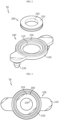
- FIG. 2 is an exploded perspective view of a bushing gasket of the battery pack of FIG. 1
- FIG. 3 is a front view of the bushing gasket of FIG. 2
- FIG. 4 is a rear view of the bushing gasket of FIG. 2 .
- the bushing gasket 50 may include a gasket member 100, a bushing member 200, a bolting member 300 (see FIGS. 5 to 7 ), and a nut member 400 (see FIGS. 5 to 7 ).
- the gasket member 100 may support the case tray 20.
- the gasket member 100 may include a gasket body 110, a guide pin 130, and a gasket bead 150.
- the gasket body 110 may include a bushing member insert hole 115 into which the bushing member 200 described later is inserted.
- the bushing member insert hole 115 may be provided at the center of the gasket body 110.
- the guide pin 130 is provided in at least one or in plurality, and may be provided in the gasket body 110. Specifically, the guide pin 130 may be provided as a pair. The pair of guide pins 130 may be disposed to face each other with the bushing member insert hole 115 interposed therebetween.
- the pair of guide pins 130 may protrude from the other side of the gasket body 110 to a predetermined length.
- the pair of guide pins 130 may be integrally formed from the gasket body 110 or separately mounted to the gasket body 110.
- the pair of guide pins 130 may form a three-point support structure together with a fastening coupling structure of the bolt member 300 and the nut member 400 described later. Accordingly, in this embodiment, when the bushing gasket 50 is coupled, a three-point support structure is formed, so that the support of the battery module 10 may be guided more stably.
- the gasket bead 150 is to further improve the sealing performance of the bushing gasket 50, is provided on the gasket body 110, and may be provided along the circumference of the bushing member insert hole 115.
- the gasket bead 150 may be elastically deformed when the bolting member 300 and the nut member 400 described later are coupled, and may be more closely attached to the case tray 20 and the case cover 30. That is, when the bolting member 300 and the nut member 400 described later are combined, the gasket bead 150 is pressurized to form surface pressure on both sides of the case tray 20 and the case cover 30, and may be more closely attached to the case tray 20 and the case cover 30.
- the bushing member 200 is for guiding fastening of the bolting member 300 and the nut member 400 described later, and may be inserted into the gasket member 100.
- the bushing member 200 may include a bushing body 210 and a bushing opening 230.
- the bushing body 210 has a substantially cylindrical ring shape and may be inserted into the bushing member insert hole 115.
- the bushing body 210 may be made of a metal material. Meanwhile, the bushing body 210 may also be made of an insulating material.
- the bushing opening 230 is formed in the center of the bushing body 210 and may allow the nut member 400 described later to pass therethrough.
- the bushing opening 230 may allow the nut member 400 described later to pass therethrough or to be fastened therethrough.
- the bolting member 300 is disposed on one side of the gasket member 100 and may be fastened to the nut member 400 described later.
- the gasket member 100 may be fixed to the case tray 20 and the case cover 30 through fastening with the bolting member 300 and the nut member 400 described later.
- the nut member 400 is fastened to the bolting member 300, and may pass or be fastened through the bushing member 200 at the other side of the gasket member 100. Specifically, the nut member 400 may pass or be fastened through the bushing opening 230 disposed in the gasket body 110 of the gasket member 100.
- FIGS. 5 to 7 are views for describing the assembly process of the bushing gasket of the battery pack of FIG. 1 .
- the bushing gasket 50 may implement the watertight structure of the battery pack 1 together, while being disposed between the case tray 20 and the tray cover 30.
- the worker or the like allow the nut member 400 of the bushing gasket 50 to pass or be fastened through the nut member fastening hole 25 of the case tray 20 and the nut member fastening hole 35 of the tray cover 30.
- the worker or the like may seat the gasket member 100 of the bushing gasket 50 between the case tray 20 and the tray cover 30.
- the worker or the like may insert the guide pins 130 of the gasket member 100 into the guide pin insert hole 27 of the case tray 20.
- the worker or the like may fasten the bolting member 300 with the nut member 400 disposed in the bushing opening 230 of the bushing member 200 of the bushing gasket 50.
- the bushing body 210 of the bushing member 200 may prevent the bolting member 300 and the nut member 400 from moving, so that it is possible to guide a more stable fastening between the bolting member 300 and the nut member 400.
- the energy density of the battery pack 1 may be significantly increased while implementing a slimmer structure of the battery pack 1 by omitting an additional gasket seating structure.
- the assembly process of the battery pack 1 may be simplified and the manufacturing cost of the battery pack 1 may be significantly reduced by omitting an additional gasket seating structure.
- the assembly efficiency of the battery pack 1 may be remarkably improved through the bushing gasket 50 while manufacturing cost may be lowered to secure cost competitiveness.
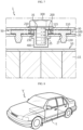
- FIG. 8 is a view for describing a vehicle according to an embodiment of the present disclosure.
- the battery pack 1 may be provided in a vehicle V as a fuel source of the vehicle.
- the battery pack 1 may be provided in electric vehicles, hybrid vehicles, commercial vehicles such as trucks and buses, and any other type of vehicles V capable of using the battery pack 1 as a fuel source.
- the battery pack 1 may be provided in other devices, instruments, and facilities, such as an energy storage system using a secondary battery, in addition to the vehicle V.
- the battery pack 1 and devices, instruments, and facilities having the battery pack 1 such as the vehicle V include the battery module 10 described above, a battery pack 1 having all of the advantages due to the battery module 10 described above, and devices, instruments, and facilities such as a vehicle V having such a battery pack 1 may be implemented.
- a battery pack 1 capable of increasing energy density and securing sealing performance, and a vehicle V including the battery pack.
- a battery pack 1 capable of securing cost competitiveness and a vehicle V including the battery pack.
Landscapes
- Chemical & Material Sciences (AREA)
- Chemical Kinetics & Catalysis (AREA)
- Electrochemistry (AREA)
- General Chemical & Material Sciences (AREA)
- Engineering & Computer Science (AREA)
- Aviation & Aerospace Engineering (AREA)
- Battery Mounting, Suspending (AREA)
Abstract
Description
- The present disclosure relates to a battery pack and a vehicle including the same.
- The present application claims priority to
Korean Patent Application No. 10-2021-0161760 filed on November 22, 2021 - Secondary batteries have high applicability according to product groups and electrical characteristics such as high energy density, and thus, are commonly applied not only to mobile devices but also to electric vehicles (EVs) or hybrid vehicles (HEVs) driven by electric power sources. Because secondary batteries may radically reduce the use of fossil fuel and do not generate any by-products that come with energy consumption, the secondary batteries are gaining attention as a new alternative energy source for improving eco-friendliness and energy efficiency.
- Types of secondary batteries that are currently widely used include lithium-ion batteries, lithium polymer batteries, nickel cadmium batteries, nickel hydride batteries, and nickel zinc batteries. An operating voltage of a unit secondary battery cell, that is, a unit battery cell, ranges from about 2.5 V to about 4.5 V. Accordingly, when a higher output voltage is required, a battery pack may be configured by connecting a plurality of battery cells in series. Also, a battery pack may be configured by connecting a plurality of battery cells in parallel according to charge/discharge capacity required for the battery pack. Accordingly, the number of battery cells included in a battery pack may be set in various ways according to a required output voltage or charge/discharge capacity.
- When a battery pack is configured by connecting a plurality of battery cells in series/parallel, a method of first configuring a battery module including at least one battery cell and adding other elements by using the at least one battery module to configure a battery pack is general.
- A conventional battery pack generally includes at least one battery module including at least one battery cell, a case tray supporting the at least one battery module, and a tray cover coupled to the case tray.
- On the other hand, in the case of a conventional battery pack, in order to implement a watertight structure, a sealing gasket is assembled with the case tray and the tray cover. In the case of a conventional battery pack, a separate gasket mounting structure such as a flange or a groove for seating the sealing gasket on the case tray or tray cover is additionally made to assemble the sealing gasket.
- However, such a conventional separate gasket mounting structure occupies a considerable space or volume in the battery pack structure, increasing the size of the entire battery pack and reducing the energy density of the battery pack.
- In addition, in the case of a conventional separate gasket mounting structure, there is also a problem of reducing cost competitiveness by causing an increase in manufacturing cost due to an additional molding process of the case tray or the tray cover for forming such a separate additional structure.
- The present disclosure is designed to solve the problems of the related art, and therefore the present disclosure is directed to providing a battery pack capable of increasing energy density and securing sealing performance, and a vehicle including the battery pack.
- In addition, another object of the present disclosure is to provide a battery pack capable of securing cost competitiveness and a vehicle including the battery pack.
- In one aspect of the present disclosure, there is provided a battery pack comprising: at least one battery module including at least one battery cell; a case tray configured to support the at least one battery module; a tray cover coupled to the case tray; and at least one bushing gasket configured to connect the case tray and the tray cover and to support the case tray on at least three points.
- The bushing gasket may include: a gasket member configured to support the case tray; a bushing member inserted into the gasket member; a bolting member disposed on one side of the gasket member; and a nut member fastened with the bolting member and configured to pass through the bushing member on the other side of the gasket member.
- The gasket member may include: a gasket body provided with a bushing member insert hole into which the bushing member is inserted; and at least one guide pin provided on the gasket body.
- The at least one guide pin may be formed to protrude from the other side of the gasket body to a predetermined length.
- The guide pin may be provided as a pair, and the pair of guide pins may be disposed with the bushing member insert hole interposed therebetween.
- The gasket member may include a gasket bead provided on the gasket body and provided along the circumference of the bushing member insert hole.
- The bushing member may include: a bushing body inserted into the bushing member insert hole; and a bushing opening formed in the bushing body configured to allow the nut member to pass therethrough.
- The tray cover may be provided with a nut member insert hole through which the nut member passes.
- The bushing gasket may be provided in plurality, and the plurality of bushing gaskets may be spaced apart from each other by a predetermined distance.
- In another aspect of the present disclosure, there is also provided a vehicle including at least one battery pack according to the above embodiments.
- According to various embodiments as described above, it is possible to provide a battery pack capable of increasing energy density and securing sealing performance, and a vehicle including the battery pack.
- In addition, according to various embodiments as described above, it is possible to provide a battery pack capable of securing cost competitiveness and a vehicle including the battery pack.
- The accompanying drawings illustrate a preferred embodiment of the present disclosure and together with the foregoing disclosure, serve to provide further understanding of the technical features of the present disclosure, and thus, the present disclosure is not construed as being limited to the drawing.
-
FIG. 1 is a view for describing a battery pack according to an embodiment of the present disclosure. -
FIG. 2 is an exploded perspective view of a bushing gasket of the battery pack ofFIG. 1 . -
FIG. 3 is a front view of the bushing gasket ofFIG. 2 . -
FIG. 4 is a rear view of the bushing gasket ofFIG. 2 . -
FIGS. 5 to 7 are views for describing the assembly process of the bushing gasket of the battery pack ofFIG. 1 . -
FIG. 8 is a view for describing a vehicle according to an embodiment of the present disclosure. - The present disclosure will now be described more fully with reference to the accompanying drawings, in which exemplary embodiments of the present disclosure are shown. These embodiments are provided so that the present disclosure will be thorough and complete, and will fully convey the concept of the present disclosure to one of ordinary skill in the art, and the present disclosure may be embodied in many different forms and should not be construed as being limited to the embodiments set forth herein. In addition, in order to help the understanding of the present disclosure, the accompanying drawings are not drawn to scale, but dimensions of some components may be exaggerated.
-
FIG. 1 is a view for describing a battery pack according to an embodiment of the present disclosure. - Referring to
FIG. 1 , abattery pack 1 may be provided in a vehicle such as an electric vehicle or a hybrid vehicle as an energy source. Thebattery pack 1 may be mounted on the body of the vehicle, and may be mounted on the lower part of the body of the vehicle. - The
battery pack 1 may include abattery module 10, acase tray 20, atray cover 30, and abushing gasket 50. - The
battery module 10 may be provided in at least one or in plurality. Thebattery module 10 may include abattery cell 15. - The
battery cell 15 may be provided in at least one or in plurality. Thebattery cell 15 is a secondary battery, and may be provided as a pouch-type secondary battery, a prismatic secondary battery, or a cylindrical secondary battery. Hereinafter, in this embodiment, thebattery cell 15 will be described as being provided as a pouch-type secondary battery. - The
case tray 20 supports the at least onebattery module 10 and may be mounted on a machine or instrument using thebattery pack 1 as an energy source. By way of example, thecase tray 20 may be mounted on a vehicle such as an electric vehicle. - The
case tray 20 may include a nut member fastening hole 25 (seeFIGS. 5 to 7 ) and a guide pin insert hole 27 (seeFIGS. 5 to 7 ). - The nut member fastening
hole 25 may be provided in at least one or in plurality. Anut member 400 of the bushinggasket 50 described later may pass or be fastened through the nutmember fastening hole 25. - The nut member fastening
hole 25 may be provided near the edge of thecase tray 20. In this regard, the nut member fasteninghole 25 may also be formed in other parts other than the vicinity of the edge of the case tray 20 for fastening of thebushing gasket 50 described later. - The guide
pin insert hole 27 may be provided in at least one or in plurality so as to face each other with the nutmember fastening hole 25 interposed therebetween. Aguide pin 130 of the bushinggasket 50 described later may be inserted through the guidepin insert hole 27. - The
tray cover 30 is coupled with thecase tray 20, and may reinforce the strength of thecase tray 20. Thetray cover 30 may be mounted on an upper edge of thecase tray 20. It is not limited thereto, and thetray cover 30 may also be provided in a shape capable of covering the upper side of thecase tray 20 and coupled to thecase tray 20, of course. - A nut member fastening hole 35 (see
FIGS. 5 to 7 ) may be provided in thetray cover 30. - The nut member fastening holes 35 may be provided in at least one or in plurality. The
nut member 400 of thebushing gasket 50 described later may pass or be fastened through the nutmember fastening hole 35. - The nut
member fastening hole 35 may be provided near the edge of thetray cover 30. The nutmember fastening hole 35 may be formed at a position opposite to the nutmember fastening hole 25 of thecase tray 20. Meanwhile, the nutmember fastening hole 35 may also be formed at other parts other than the vicinity of the edge of thetray cover 30 for fastening of thebushing gasket 50 described later. - The
bushing gasket 50 is for implementing a watertight structure, connects thecase tray 20 and thetray cover 30, and may support thecase tray 20 on at least three points. - The
bushing gasket 50 may more stably support thebattery module 10 together with thecase tray 20 and thetray cover 30 through this three-point support structure. - The
bushing gasket 50 may be provided in plurality. The plurality ofbushing gaskets 50 may be spaced apart from each other by a predetermined distance when thecase tray 20 and thetray cover 30 are connected. - Hereinafter, the
bushing gasket 50 according to this embodiment will be looked at in more detail. -
FIG. 2 is an exploded perspective view of a bushing gasket of the battery pack ofFIG. 1 ,FIG. 3 is a front view of the bushing gasket ofFIG. 2 , andFIG. 4 is a rear view of the bushing gasket ofFIG. 2 . - Referring to
FIGS. 2 to 4 , thebushing gasket 50 may include agasket member 100, abushing member 200, a bolting member 300 (seeFIGS. 5 to 7 ), and a nut member 400 (seeFIGS. 5 to 7 ). - The
gasket member 100 may support thecase tray 20. - The
gasket member 100 may include agasket body 110, aguide pin 130, and agasket bead 150. - The
gasket body 110 may include a bushingmember insert hole 115 into which thebushing member 200 described later is inserted. The bushingmember insert hole 115 may be provided at the center of thegasket body 110. - The
guide pin 130 is provided in at least one or in plurality, and may be provided in thegasket body 110. Specifically, theguide pin 130 may be provided as a pair. The pair of guide pins 130 may be disposed to face each other with the bushingmember insert hole 115 interposed therebetween. - The pair of guide pins 130 may protrude from the other side of the
gasket body 110 to a predetermined length. Here, the pair of guide pins 130 may be integrally formed from thegasket body 110 or separately mounted to thegasket body 110. - The pair of guide pins 130 may form a three-point support structure together with a fastening coupling structure of the
bolt member 300 and thenut member 400 described later. Accordingly, in this embodiment, when thebushing gasket 50 is coupled, a three-point support structure is formed, so that the support of thebattery module 10 may be guided more stably. - The
gasket bead 150 is to further improve the sealing performance of thebushing gasket 50, is provided on thegasket body 110, and may be provided along the circumference of the bushingmember insert hole 115. - The
gasket bead 150 may be elastically deformed when the boltingmember 300 and thenut member 400 described later are coupled, and may be more closely attached to thecase tray 20 and thecase cover 30. That is, when the boltingmember 300 and thenut member 400 described later are combined, thegasket bead 150 is pressurized to form surface pressure on both sides of thecase tray 20 and thecase cover 30, and may be more closely attached to thecase tray 20 and thecase cover 30. - The
bushing member 200 is for guiding fastening of the boltingmember 300 and thenut member 400 described later, and may be inserted into thegasket member 100. - The
bushing member 200 may include abushing body 210 and abushing opening 230. - The
bushing body 210 has a substantially cylindrical ring shape and may be inserted into the bushingmember insert hole 115. Thebushing body 210 may be made of a metal material. Meanwhile, thebushing body 210 may also be made of an insulating material. - The
bushing opening 230 is formed in the center of thebushing body 210 and may allow thenut member 400 described later to pass therethrough. Here, thebushing opening 230 may allow thenut member 400 described later to pass therethrough or to be fastened therethrough. - The bolting
member 300 is disposed on one side of thegasket member 100 and may be fastened to thenut member 400 described later. Thegasket member 100 may be fixed to thecase tray 20 and the case cover 30 through fastening with the boltingmember 300 and thenut member 400 described later. - The
nut member 400 is fastened to the boltingmember 300, and may pass or be fastened through thebushing member 200 at the other side of thegasket member 100. Specifically, thenut member 400 may pass or be fastened through thebushing opening 230 disposed in thegasket body 110 of thegasket member 100. - Hereinafter, the assembly process of the
bushing gasket 50 according to this embodiment will be described in more detail. -
FIGS. 5 to 7 are views for describing the assembly process of the bushing gasket of the battery pack ofFIG. 1 . - Referring to
FIGS. 5 to 7 , during the manufacturing process of thebattery pack 1, a worker or the like may seat thebattery module 10 in thecase tray 20 and then couple thecase tray 20 and thetray cover 30. Here, thebushing gasket 50 may implement the watertight structure of thebattery pack 1 together, while being disposed between thecase tray 20 and thetray cover 30. - Specifically, the worker or the like allow the
nut member 400 of thebushing gasket 50 to pass or be fastened through the nutmember fastening hole 25 of thecase tray 20 and the nutmember fastening hole 35 of thetray cover 30. - In addition, the worker or the like may seat the
gasket member 100 of thebushing gasket 50 between thecase tray 20 and thetray cover 30. Here, the worker or the like may insert the guide pins 130 of thegasket member 100 into the guidepin insert hole 27 of thecase tray 20. - Through the insertion of the guide pins 130, positioning of the
case tray 20 is guided when the boltingmember 300 and thenut member 400 are coupled, and it is possible to prevent position deviation or position misalignment of thecase tray 20 or thetray cover 30 that may occur during the coupling. - Then, the worker or the like may fasten the bolting
member 300 with thenut member 400 disposed in thebushing opening 230 of thebushing member 200 of thebushing gasket 50. Here, when the boltingmember 300 and thenut member 400 are coupled, thebushing body 210 of thebushing member 200 may prevent the boltingmember 300 and thenut member 400 from moving, so that it is possible to guide a more stable fastening between the boltingmember 300 and thenut member 400. - In this embodiment, through the
bushing gasket 50, it is possible to effectively secure the sealing performance of thebattery pack 1 by implementing a simpler bolt nut assembly structure without a separate gasket seating structure such as a conventional flange or groove. - Accordingly, in this embodiment, the energy density of the
battery pack 1 may be significantly increased while implementing a slimmer structure of thebattery pack 1 by omitting an additional gasket seating structure. - In addition, in this embodiment, the assembly process of the
battery pack 1 may be simplified and the manufacturing cost of thebattery pack 1 may be significantly reduced by omitting an additional gasket seating structure. - Therefore, in this embodiment, the assembly efficiency of the
battery pack 1 may be remarkably improved through thebushing gasket 50 while manufacturing cost may be lowered to secure cost competitiveness. -
FIG. 8 is a view for describing a vehicle according to an embodiment of the present disclosure. - Referring to
FIG. 8 , thebattery pack 1 may be provided in a vehicle V as a fuel source of the vehicle. By way of example, thebattery pack 1 may be provided in electric vehicles, hybrid vehicles, commercial vehicles such as trucks and buses, and any other type of vehicles V capable of using thebattery pack 1 as a fuel source. - Also, the
battery pack 1 may be provided in other devices, instruments, and facilities, such as an energy storage system using a secondary battery, in addition to the vehicle V. - As such, since the
battery pack 1 and devices, instruments, and facilities having thebattery pack 1 such as the vehicle V according to this embodiment include thebattery module 10 described above, abattery pack 1 having all of the advantages due to thebattery module 10 described above, and devices, instruments, and facilities such as a vehicle V having such abattery pack 1 may be implemented. - According to various embodiments as described above, it is possible to provide a
battery pack 1 capable of increasing energy density and securing sealing performance, and a vehicle V including the battery pack. - In addition, according to various embodiments as described above, it is possible to provide a
battery pack 1 capable of securing cost competitiveness and a vehicle V including the battery pack. - While the preferred embodiments of the present disclosure have been shown and described, the present disclosure is not limited to the specific embodiments described above, various modifications may be made by one of ordinary skill in the art to which the present disclosure pertains without departing from the gist of the present disclosure as defined by the claims, and these modifications should not be individually understood from the technical feature or prospect of the present disclosure.
Claims (10)
- A battery pack comprising:at least one battery module including at least one battery cell;a case tray configured to support the at least one battery module;a tray cover coupled to the case tray; andat least one bushing gasket configured to connect the case tray and the tray cover and to support the case tray on at least three points.
- The battery pack according to claim 1, wherein the bushing gasket includes:a gasket member configured to support the case tray;a bushing member inserted into the gasket member;a bolting member disposed on one side of the gasket member; anda nut member fastened with the bolting member and configured to pass through the bushing member on the other side of the gasket member.
- The battery pack according to claim 2, wherein the gasket member includes:a gasket body provided with a bushing member insert hole into which the bushing member is inserted; andat least one guide pin provided on the gasket body.
- The battery pack according to claim 3, wherein the at least one guide pin is formed to protrude from the other side of the gasket body to a predetermined length.
- The battery pack according to claim 3, wherein the guide pin is provided as a pair, and
wherein the pair of guide pins are disposed with the bushing member insert hole interposed therebetween. - The battery pack according to claim 3, wherein the gasket member includes a gasket bead provided on the gasket body and provided along the circumference of the bushing member insert hole.
- The battery pack according to claim 2, wherein the bushing member includes:a bushing body inserted into the bushing member insert hole; anda bushing opening formed in the bushing body configured to allow the nut member to pass therethrough.
- The battery pack according to claim 1, wherein the tray cover is provided with a nut member insert hole through which the nut member passes.
- The battery pack according to claim 1, wherein the bushing gasket is provided in plurality, and
wherein the plurality of bushing gaskets are spaced apart from each other by a predetermined distance. - A vehicle comprising at least one battery pack according to claim 1.
Applications Claiming Priority (2)
| Application Number | Priority Date | Filing Date | Title |
|---|---|---|---|
| KR1020210161760A KR20230075298A (en) | 2021-11-22 | 2021-11-22 | Battery pack and vehicle comprising the battery pack |
| PCT/KR2022/015148 WO2023090641A1 (en) | 2021-11-22 | 2022-10-07 | Battery pack and vehicle comprising same |
Publications (2)
| Publication Number | Publication Date |
|---|---|
| EP4287374A1 true EP4287374A1 (en) | 2023-12-06 |
| EP4287374A4 EP4287374A4 (en) | 2024-10-16 |
Family
ID=86397267
Family Applications (1)
| Application Number | Title | Priority Date | Filing Date |
|---|---|---|---|
| EP22895850.0A Pending EP4287374A4 (en) | 2021-11-22 | 2022-10-07 | BATTERY PACK AND VEHICLE WITH IT |
Country Status (6)
| Country | Link |
|---|---|
| US (1) | US20240234886A9 (en) |
| EP (1) | EP4287374A4 (en) |
| JP (1) | JP7674048B2 (en) |
| KR (1) | KR20230075298A (en) |
| CN (1) | CN116830367A (en) |
| WO (1) | WO2023090641A1 (en) |
Families Citing this family (2)
| Publication number | Priority date | Publication date | Assignee | Title |
|---|---|---|---|---|
| CN115528504A (en) * | 2021-06-24 | 2022-12-27 | 福特全球技术公司 | Bracket assembly for battery pack and battery pack including same |
| WO2026023715A1 (en) * | 2024-07-24 | 2026-01-29 | 엘지전자 주식회사 | Riveting device for cylindrical battery |
Family Cites Families (6)
| Publication number | Priority date | Publication date | Assignee | Title |
|---|---|---|---|---|
| JP5786974B2 (en) * | 2014-01-15 | 2015-09-30 | 三菱自動車工業株式会社 | Battery case |
| KR101725908B1 (en) * | 2014-11-17 | 2017-04-11 | 주식회사 엘지화학 | Battery Pack Having Portion for Fixing of Gasket |
| KR102123661B1 (en) * | 2016-02-22 | 2020-06-16 | 주식회사 엘지화학 | Battery pack and vehicle comprising the battery pack |
| CN107565069A (en) * | 2016-06-30 | 2018-01-09 | 北京普莱德新能源电池科技有限公司 | A kind of electrokinetic cell lodge body, electrokinetic cell bag, electric automobile |
| KR102084152B1 (en) * | 2016-11-04 | 2020-03-03 | 주식회사 엘지화학 | Battery Pack having tray stopper for preventing spring back of Pack cover |
| KR102779617B1 (en) * | 2019-12-02 | 2025-03-10 | 주식회사 엘지에너지솔루션 | Battery pack and device including the same |
-
2021
- 2021-11-22 KR KR1020210161760A patent/KR20230075298A/en not_active Ceased
-
2022
- 2022-10-07 JP JP2023553372A patent/JP7674048B2/en active Active
- 2022-10-07 CN CN202280013947.9A patent/CN116830367A/en active Pending
- 2022-10-07 WO PCT/KR2022/015148 patent/WO2023090641A1/en not_active Ceased
- 2022-10-07 EP EP22895850.0A patent/EP4287374A4/en active Pending
- 2022-10-07 US US18/279,194 patent/US20240234886A9/en active Pending
Also Published As
| Publication number | Publication date |
|---|---|
| EP4287374A4 (en) | 2024-10-16 |
| KR20230075298A (en) | 2023-05-31 |
| CN116830367A (en) | 2023-09-29 |
| US20240136620A1 (en) | 2024-04-25 |
| JP7674048B2 (en) | 2025-05-09 |
| WO2023090641A1 (en) | 2023-05-25 |
| JP2024509155A (en) | 2024-02-29 |
| US20240234886A9 (en) | 2024-07-11 |
Similar Documents
| Publication | Publication Date | Title |
|---|---|---|
| EP3836244A1 (en) | Battery module and battery pack comprising battery module | |
| EP4071903A1 (en) | Battery pack and vehicle comprising same | |
| US12609398B2 (en) | Battery pack and vehicle including the same | |
| EP4203159A2 (en) | Battery module, battery pack including same, and vehicle | |
| US20240136620A1 (en) | Battery pack and vehicle including the same | |
| KR102123661B1 (en) | Battery pack and vehicle comprising the battery pack | |
| KR102949549B1 (en) | Battery pack and vehicle comprising the battery pack | |
| US12183936B2 (en) | Battery pack and vehicle comprising same battery pack | |
| KR102917540B1 (en) | Cell module assembly and method for manufacturing the same | |
| US12431575B2 (en) | Battery pack having improved fastening structure and vehicle comprising same | |
| KR102770325B1 (en) | Battery pack and vehicle comprising the battery pack | |
| EP4276995A1 (en) | Multi-battery pack having compact structure | |
| EP4231418A1 (en) | Battery pack assembly guide jig | |
| KR20200055336A (en) | Battery pack | |
| KR20240025401A (en) | Battery cell assembly | |
| EP4287378A1 (en) | Battery pack and vehicle comprising same | |
| EP4661160A1 (en) | Battery pack and vehicle comprising same | |
| EP4742369A1 (en) | Battery pack and vehicle comprising same | |
| KR20200104625A (en) | Battery mount structure for making provision for collision and vehicle having the same | |
| KR20200104621A (en) | Catridge for battery cell having counterbar hole and battery module assembly including the same | |
| KR20250053590A (en) | Battery pack and vehicle comprising the same | |
| KR20250154129A (en) | Tray for activating of battery cell and battery cell produced using the same, and battery pack and vehicle comprising battery cells |
Legal Events
| Date | Code | Title | Description |
|---|---|---|---|
| STAA | Information on the status of an ep patent application or granted ep patent |
Free format text: STATUS: THE INTERNATIONAL PUBLICATION HAS BEEN MADE |
|
| PUAI | Public reference made under article 153(3) epc to a published international application that has entered the european phase |
Free format text: ORIGINAL CODE: 0009012 |
|
| STAA | Information on the status of an ep patent application or granted ep patent |
Free format text: STATUS: REQUEST FOR EXAMINATION WAS MADE |
|
| 17P | Request for examination filed |
Effective date: 20230830 |
|
| AK | Designated contracting states |
Kind code of ref document: A1 Designated state(s): AL AT BE BG CH CY CZ DE DK EE ES FI FR GB GR HR HU IE IS IT LI LT LU LV MC ME MK MT NL NO PL PT RO RS SE SI SK SM TR |
|
| A4 | Supplementary search report drawn up and despatched |
Effective date: 20240918 |
|
| RIC1 | Information provided on ipc code assigned before grant |
Ipc: H01M 50/249 20210101ALI20240912BHEP Ipc: H01M 50/204 20210101AFI20240912BHEP |
|
| DAV | Request for validation of the european patent (deleted) | ||
| DAX | Request for extension of the european patent (deleted) | ||
| STAA | Information on the status of an ep patent application or granted ep patent |
Free format text: STATUS: EXAMINATION IS IN PROGRESS |
|
| 17Q | First examination report despatched |
Effective date: 20250630 |