EP4287372A1 - Assembled battery and battery pack - Google Patents
Assembled battery and battery pack Download PDFInfo
- Publication number
- EP4287372A1 EP4287372A1 EP22746075.5A EP22746075A EP4287372A1 EP 4287372 A1 EP4287372 A1 EP 4287372A1 EP 22746075 A EP22746075 A EP 22746075A EP 4287372 A1 EP4287372 A1 EP 4287372A1
- Authority
- EP
- European Patent Office
- Prior art keywords
- battery
- assembled battery
- heat dissipation
- elastic member
- peripheral surface
- Prior art date
- Legal status (The legal status is an assumption and is not a legal conclusion. Google has not performed a legal analysis and makes no representation as to the accuracy of the status listed.)
- Granted
Links
Images


Classifications
-
- H—ELECTRICITY
- H01—ELECTRIC ELEMENTS
- H01M—PROCESSES OR MEANS, e.g. BATTERIES, FOR THE DIRECT CONVERSION OF CHEMICAL ENERGY INTO ELECTRICAL ENERGY
- H01M50/00—Constructional details or processes of manufacture of the non-active parts of electrochemical cells other than fuel cells, e.g. hybrid cells
- H01M50/20—Mountings; Secondary casings or frames; Racks, modules or packs; Suspension devices; Shock absorbers; Transport or carrying devices; Holders
- H01M50/289—Mountings; Secondary casings or frames; Racks, modules or packs; Suspension devices; Shock absorbers; Transport or carrying devices; Holders characterised by spacing elements or positioning means within frames, racks or packs
- H01M50/293—Mountings; Secondary casings or frames; Racks, modules or packs; Suspension devices; Shock absorbers; Transport or carrying devices; Holders characterised by spacing elements or positioning means within frames, racks or packs characterised by the material
-
- H—ELECTRICITY
- H01—ELECTRIC ELEMENTS
- H01M—PROCESSES OR MEANS, e.g. BATTERIES, FOR THE DIRECT CONVERSION OF CHEMICAL ENERGY INTO ELECTRICAL ENERGY
- H01M10/00—Secondary cells; Manufacture thereof
- H01M10/60—Heating or cooling; Temperature control
- H01M10/61—Types of temperature control
- H01M10/613—Cooling or keeping cold
-
- H—ELECTRICITY
- H01—ELECTRIC ELEMENTS
- H01M—PROCESSES OR MEANS, e.g. BATTERIES, FOR THE DIRECT CONVERSION OF CHEMICAL ENERGY INTO ELECTRICAL ENERGY
- H01M10/00—Secondary cells; Manufacture thereof
- H01M10/60—Heating or cooling; Temperature control
- H01M10/62—Heating or cooling; Temperature control specially adapted for specific applications
- H01M10/623—Portable devices, e.g. mobile telephones, cameras or pacemakers
- H01M10/6235—Power tools
-
- H—ELECTRICITY
- H01—ELECTRIC ELEMENTS
- H01M—PROCESSES OR MEANS, e.g. BATTERIES, FOR THE DIRECT CONVERSION OF CHEMICAL ENERGY INTO ELECTRICAL ENERGY
- H01M10/00—Secondary cells; Manufacture thereof
- H01M10/60—Heating or cooling; Temperature control
- H01M10/65—Means for temperature control structurally associated with the cells
- H01M10/653—Means for temperature control structurally associated with the cells characterised by electrically insulating or thermally conductive materials
-
- H—ELECTRICITY
- H01—ELECTRIC ELEMENTS
- H01M—PROCESSES OR MEANS, e.g. BATTERIES, FOR THE DIRECT CONVERSION OF CHEMICAL ENERGY INTO ELECTRICAL ENERGY
- H01M10/00—Secondary cells; Manufacture thereof
- H01M10/60—Heating or cooling; Temperature control
- H01M10/65—Means for temperature control structurally associated with the cells
- H01M10/655—Solid structures for heat exchange or heat conduction
- H01M10/6554—Rods or plates
-
- H—ELECTRICITY
- H01—ELECTRIC ELEMENTS
- H01M—PROCESSES OR MEANS, e.g. BATTERIES, FOR THE DIRECT CONVERSION OF CHEMICAL ENERGY INTO ELECTRICAL ENERGY
- H01M10/00—Secondary cells; Manufacture thereof
- H01M10/60—Heating or cooling; Temperature control
- H01M10/65—Means for temperature control structurally associated with the cells
- H01M10/655—Solid structures for heat exchange or heat conduction
- H01M10/6554—Rods or plates
- H01M10/6555—Rods or plates arranged between the cells
-
- H—ELECTRICITY
- H01—ELECTRIC ELEMENTS
- H01M—PROCESSES OR MEANS, e.g. BATTERIES, FOR THE DIRECT CONVERSION OF CHEMICAL ENERGY INTO ELECTRICAL ENERGY
- H01M50/00—Constructional details or processes of manufacture of the non-active parts of electrochemical cells other than fuel cells, e.g. hybrid cells
- H01M50/20—Mountings; Secondary casings or frames; Racks, modules or packs; Suspension devices; Shock absorbers; Transport or carrying devices; Holders
- H01M50/204—Racks, modules or packs for multiple batteries or multiple cells
-
- H—ELECTRICITY
- H01—ELECTRIC ELEMENTS
- H01M—PROCESSES OR MEANS, e.g. BATTERIES, FOR THE DIRECT CONVERSION OF CHEMICAL ENERGY INTO ELECTRICAL ENERGY
- H01M50/00—Constructional details or processes of manufacture of the non-active parts of electrochemical cells other than fuel cells, e.g. hybrid cells
- H01M50/20—Mountings; Secondary casings or frames; Racks, modules or packs; Suspension devices; Shock absorbers; Transport or carrying devices; Holders
- H01M50/204—Racks, modules or packs for multiple batteries or multiple cells
- H01M50/207—Racks, modules or packs for multiple batteries or multiple cells characterised by their shape
- H01M50/213—Racks, modules or packs for multiple batteries or multiple cells characterised by their shape adapted for cells having curved cross-section, e.g. round or elliptic
-
- H—ELECTRICITY
- H01—ELECTRIC ELEMENTS
- H01M—PROCESSES OR MEANS, e.g. BATTERIES, FOR THE DIRECT CONVERSION OF CHEMICAL ENERGY INTO ELECTRICAL ENERGY
- H01M50/00—Constructional details or processes of manufacture of the non-active parts of electrochemical cells other than fuel cells, e.g. hybrid cells
- H01M50/40—Separators; Membranes; Diaphragms; Spacing elements inside cells
- H01M50/471—Spacing elements inside cells other than separators, membranes or diaphragms; Manufacturing processes thereof
- H01M50/474—Spacing elements inside cells other than separators, membranes or diaphragms; Manufacturing processes thereof characterised by their position inside the cells
-
- H—ELECTRICITY
- H01—ELECTRIC ELEMENTS
- H01M—PROCESSES OR MEANS, e.g. BATTERIES, FOR THE DIRECT CONVERSION OF CHEMICAL ENERGY INTO ELECTRICAL ENERGY
- H01M50/00—Constructional details or processes of manufacture of the non-active parts of electrochemical cells other than fuel cells, e.g. hybrid cells
- H01M50/40—Separators; Membranes; Diaphragms; Spacing elements inside cells
- H01M50/471—Spacing elements inside cells other than separators, membranes or diaphragms; Manufacturing processes thereof
- H01M50/477—Spacing elements inside cells other than separators, membranes or diaphragms; Manufacturing processes thereof characterised by their shape
-
- H—ELECTRICITY
- H01—ELECTRIC ELEMENTS
- H01M—PROCESSES OR MEANS, e.g. BATTERIES, FOR THE DIRECT CONVERSION OF CHEMICAL ENERGY INTO ELECTRICAL ENERGY
- H01M50/00—Constructional details or processes of manufacture of the non-active parts of electrochemical cells other than fuel cells, e.g. hybrid cells
- H01M50/40—Separators; Membranes; Diaphragms; Spacing elements inside cells
- H01M50/471—Spacing elements inside cells other than separators, membranes or diaphragms; Manufacturing processes thereof
- H01M50/48—Spacing elements inside cells other than separators, membranes or diaphragms; Manufacturing processes thereof characterised by the material
- H01M50/486—Organic material
-
- H—ELECTRICITY
- H01—ELECTRIC ELEMENTS
- H01M—PROCESSES OR MEANS, e.g. BATTERIES, FOR THE DIRECT CONVERSION OF CHEMICAL ENERGY INTO ELECTRICAL ENERGY
- H01M10/00—Secondary cells; Manufacture thereof
- H01M10/60—Heating or cooling; Temperature control
- H01M10/65—Means for temperature control structurally associated with the cells
- H01M10/656—Means for temperature control structurally associated with the cells characterised by the type of heat-exchange fluid
- H01M10/6561—Gases
- H01M10/6562—Gases with free flow by convection only
-
- H—ELECTRICITY
- H01—ELECTRIC ELEMENTS
- H01M—PROCESSES OR MEANS, e.g. BATTERIES, FOR THE DIRECT CONVERSION OF CHEMICAL ENERGY INTO ELECTRICAL ENERGY
- H01M2220/00—Batteries for particular applications
- H01M2220/20—Batteries in motive systems, e.g. vehicle, ship, plane
-
- H—ELECTRICITY
- H01—ELECTRIC ELEMENTS
- H01M—PROCESSES OR MEANS, e.g. BATTERIES, FOR THE DIRECT CONVERSION OF CHEMICAL ENERGY INTO ELECTRICAL ENERGY
- H01M2220/00—Batteries for particular applications
- H01M2220/30—Batteries in portable systems, e.g. mobile phone, laptop
-
- Y—GENERAL TAGGING OF NEW TECHNOLOGICAL DEVELOPMENTS; GENERAL TAGGING OF CROSS-SECTIONAL TECHNOLOGIES SPANNING OVER SEVERAL SECTIONS OF THE IPC; TECHNICAL SUBJECTS COVERED BY FORMER USPC CROSS-REFERENCE ART COLLECTIONS [XRACs] AND DIGESTS
- Y02—TECHNOLOGIES OR APPLICATIONS FOR MITIGATION OR ADAPTATION AGAINST CLIMATE CHANGE
- Y02E—REDUCTION OF GREENHOUSE GAS [GHG] EMISSIONS, RELATED TO ENERGY GENERATION, TRANSMISSION OR DISTRIBUTION
- Y02E60/00—Enabling technologies; Technologies with a potential or indirect contribution to GHG emissions mitigation
- Y02E60/10—Energy storage using batteries
Definitions
- the present invention relates to an assembled battery and a battery pack which are to be mounted, for example, in power tools, etc. and used as power sources for electric motors, etc.
- Power tools generally include ones which are used in the state of being connected to the so-called commercial power source and ones which have an assembled battery mounted therein that serves as a power source for an electric motor for driving.
- the power tools having an assembled battery mounted therein are frequently used from the point of view of the excellent handleability, etc.
- An assembled battery is a battery in which a plurality of battery cells is connected serially or in parallel.
- battery cells are enclosed in a battery case made of, for example, a polycarbonate and united therewith, and the assembled battery is housed inside a power tool.
- Patent Document 1 proposes an assembled battery in which in case where abnormal heat generation has occurred, for example, because an overcurrent has flowed into a battery cell, the burning can be prevented or inhibited from spreading to adjoining battery cells.
- the assembled battery described in Patent Document 1 is configured of a plurality of battery cells and a block for holding the battery cells, the block being made of a metallic material and composed of a plurality of small blocks. The dimensions of the gap between the block and each battery cell are regulated.
- Patent Document 1 states that in the assembled battery described therein, which has such configuration, heat can be rapidly diffused because the block holding the battery cells is made of a metallic material.
- Patent Document 2 discloses an anti-firing material capable of reducing the risk of firing in electricity storage devices.
- the above anti-firing material is, for example, a porous carbonaceous material having a noncombustible gas, aqueous solvent, or noncombustible solvent adsorbed into the pores and onto the surface thereof.
- Patent Document 2 as stated above describes that in case of abnormality, when the secondary battery has released the electrolytic solution or a gaseous component, e.g., an electrolytic-solution decomposition gas, an effect can be obtained in which the gaseous component passes through the above anti-firing material and is thereby reduced in temperature.
- a gaseous component e.g., an electrolytic-solution decomposition gas
- the assembled battery described in Patent Document 1 necessitates a plurality of blocks and the blocks need to be designed in accordance with the electronic appliance, power tool, or the like in which the assembled battery is to be mounted, since the gaps between the blocks and the battery cells are varied. There is hence a problem in that the design of the blocks and fabrication of the assembled battery are complicated.
- the anti-firing material although effective against the evolution of a gaseous component from a secondary battery in case of abnormality, is unable to lower the temperature of the batteries themselves in cases when the battery cells which have been fabricated into an assembled battery are subjected to charge/discharge cycling (i.e., "during ordinary use") and in case of abnormality.
- the present invention is made in view of the aforementioned problems, and an object of the invention is to provide an assembled battery and a battery pack which are easy to design and fabricate and in which during ordinary use and in case of abnormality, heat transfer between battery cells can be inhibited and the battery cells can be efficiently cooled to inhibit the occurrence of thermal runaway.
- the object of the present invention is accomplished with the following configuration [1] regarding an assembled battery.
- the assembled battery of the present invention includes a flameproof material covering the peripheral surface of each battery cell, the transfer of heat between the battery cells can be inhibited during ordinary use and in case of abnormality. Since the assembled battery of the present invention includes a heat dissipation member covering the peripheral surface of the flameproof material, heat generated from each battery cell can be efficiently radiated to the outside. Furthermore, since the assembled battery of the present invention can be fabricated by merely attaching the flameproof material and the heat dissipation member to the peripheral surface of each battery cell, there is no need of changing the design of the battery case in accordance with the kind of the battery cells and fabrication of the assembled battery requires no complicated operation.
- the battery pack of the present invention includes the assembled battery encased, not only the transfer of heat between the battery cells can be inhibited and the propagation of thermal runaway can be prevented, but also this battery pack can be easily fabricated.
- the present inventor diligently made investigations in order to provide an assembled battery in which during ordinary use and in case of abnormality, heat transfer between the battery cells can be inhibited and the battery cells can be efficiently cooled to inhibit the occurrence of thermal runaway.
- FIG. 1 is a cross-sectional view schematically illustrating a battery pack containing an assembled battery according to a first embodiment of the present invention.
- the battery pack 1 is one obtained by encasing an assembled battery 10 according to a first embodiment, which is described in detail below, in a battery case 7 made of, for example, a resin.
- Each battery cell 2 has an electrode surface 2a having an electrode 3 and a peripheral surface 2b that is a surface orthogonal to the electrode surface 2a.
- the battery cells 2 have been disposed such that the peripheral surfaces 2b thereof face each other, and are connected serially or in parallel, with the electrodes 3 and a connector (not shown), etc. interposed therebetween.
- the peripheral surface 2b of each battery cell 2 is covered with a flameproof material 4 and the peripheral surface of the flameproof material 4 is covered with a heat dissipation member 8, thereby configuring the assembled battery 10.
- the heat dissipation member 8 is, for example, a tubular body which is open at both ends, and covers the peripheral surface of the battery cell 2 and flameproof material 4.
- both ends of the heat dissipation member 8 (tubular body) means one longitudinal-direction (top-bottom direction in FIG. 1 ) end of the heat dissipation member 8 and the other end thereof, namely, the open ends of the tubular body.
- the heat dissipation member 8 further covering the peripheral surface of the battery cell 2 and flameproof material 4 is made of a material having excellent thermal conductivity, as will be described later. Because of this, in cases when some of the heat was unable to be inhibited by the flameproof material 4 from being transferred and has reached the heat dissipation member 8, then the heat spreads in plane directions of the dissipation member 8 and is radiated to both end sides of the heat dissipation member 8. The battery cell 2 can hence be efficiently cooled.
- the heat dissipation member 8 is a tubular body as stated above, and is made of a material such as, for example, a metal or carbon, and has substantially no stretchability. Because of this, in cases when the gap between the heat dissipation member 8 and the battery cell 2 and flameproof material 4 is small, an effect can be obtained in which if the battery cell 2 deforms in case of abnormality, the heat dissipation member 8 inhibits the battery cell 2 from deforming. The battery case 7 can hence be inhibited from breaking.
- the covering of the battery cell 2 with the heat dissipation member 8 makes it possible to avoid a trouble, for example, that fragments of the battery cell 2, an organic electrolytic liquid present in the battery cell 2, etc. reach other battery cells 2 to exert an adverse influence.
- the battery cells 2 may be prismatic or round.
- Each flameproof material 4 preferably covers all of the peripheral surface of the battery cell 2. However, a part of the peripheral surface may be uncovered according to need, so long as the flameproof material 4 can inhibit the propagation of thermal runaway described above.
- Each heat dissipation member 8 also preferably covers all of the peripheral surface of the battery cell 2 covered with the flameproof material 4. However, a part of the peripheral surface may be uncovered according to need, so long as the heat dissipation member 8 can have the heat dissipation effect described above.
- the heat dissipation members 8 were each a tubular body open at both ends.
- the heat dissipation members 8 are not limited to tubular bodies.
- a sheet-shaped heat dissipation material may be used and wrapped around the outer surface of a battery cell 2 covered with a flameproof material 4 to form a heat dissipation member 8.
- the effect of inhibiting the battery cell 2 from deforming is lower than in the case of using the tubular heat dissipation member 8.
- the heat dissipation member formed by wrapping a sheet-shaped heat dissipation material around the peripheral surface of the flameproof material 4 can flexibly cope with the deformations during ordinary use.
- a tubular heat dissipation member 8 can be easily produced by wrapping the sheet around the outer surface of the flameproof material 4 and then fixing the free end of the wrapped sheet to a part of the wrapped sheet.
- FIG. 2 is a cross-sectional view schematically illustrating a battery pack containing an assembled battery according to a second embodiment of the present invention.
- FIGs. 2 and 3 which show the second and third embodiments described below, parts or portions that are identical with or equal to those in the first embodiment are designated by like numerals, and explanations thereon are omitted or simplified.
- the assembled battery 20 includes elastic members 5 each disposed between a flameproof material 4 and a heat dissipation member 8 over the peripheral surface 2b of a battery cell 2.
- the elastic member 5 is, for example, a tubular body which is open at both ends. The elastic member 5 covers the peripheral surface of the battery cell 2 and flameproof material 4 along the peripheral direction and presses the battery cell.
- the elastic members 5, which press the battery cells 2 have both the effect of inhibiting the battery cells 2 from deforming and the effect of absorbing deformations of the battery cells 2. That is, when a battery cell 2 deforms in case of abnormality, the heat dissipation member 8 flexibly deforms in accordance with the deformation of the battery cell 2 while inhibiting the deformation of the battery cell 2. Because of this, even when the heat dissipation member is one formed from a sheet-shaped heat dissipation material, the elastic member 5 can absorb the deformations of the battery cell 2 to inhibit the battery case 7 from breaking.
- the elastic member 5 disposed between the flameproof material 4 and the heat dissipation member 8 can absorb slight deformations of the battery cell 2 to prevent a pressure from being unnecessarily applied to adjoining battery cells 2.
- FIG. 3 is a cross-sectional view schematically illustrating a battery pack containing an assembled battery according to a third embodiment of the present invention.
- the assembled battery 30 includes elastic members 5 each disposed on the outer side of a flameproof material 4 and a heat dissipation member 8 over the peripheral surface 2b of a battery cell 2.
- the elastic member 5 is, for example, a tubular body which is open at both ends, as in the second embodiment.
- the elastic member 5 covers, along the peripheral direction, the peripheral surface of the battery cell 2 covered with both the flameproof material 4 and the heat dissipation member 8 and presses the battery cell.
- the third embodiment which has such configuration, is especially effective, for example, when heat dissipation members formed from sheet-shaped heat dissipation materials are used.
- a heat dissipation member formed from a sheet-shaped heat dissipation material is used on the peripheral surface of a battery cell 2 covered with a flameproof material 4, then the effect of inhibiting the battery cell 2 from deforming is lessened.
- an elastic member 5 has been further disposed on the peripheral surface of the heat dissipation member, it is possible, during ordinary use and in case of abnormality, to absorb deformations of the battery cell 2 while inhibiting the battery cell 2 from deforming, thereby inhibiting the battery case 7 from breaking.
- the elastic members 5 may be made of a material having heat-insulating properties, like the flameproof materials 4. Hence, by disposing such elastic members 5 on the peripheral surfaces of the heat dissipation members, a higher heat-insulating effect can be obtained.
- each elastic member 5 need not cover all of the peripheral surface of the flameproof material 4 or heat dissipation member 8, and may be one which can be expected to have the effects of elastic members 5 described above.
- each elastic member 5 may be one which covers only a part of the peripheral surface so long as the assembled battery has been configured so that the elastic member 5 covers the peripheral surface along the peripheral direction and presses the battery cell 2.
- the flameproof materials 4 to be used in the assembled batteries 10, 20, and 30 according to the embodiments preferably contain organic fibers and/or inorganic fibers, and more preferably further contain inorganic particles according to need.
- these materials which have been processed into, for example, a sheet shape. Since it is important that materials for constituting the flameproof materials 4 should have heat-insulating properties, these materials are selected from among materials having high heat-insulating performance.
- the inorganic fibers include silica-alumina fibers, alumina fibers, silica fibers, rock wool, alkaline-earth silicate fibers, glass fibers, zirconia fibers, and potassium titanate whisker fibers. These inorganic fibers are preferred from the standpoints of heat resistance, strength, availability, etc. Inorganic fibers of one kind may be used alone, or two or more kinds of inorganic fibers may be used in combination. Especially preferred of those inorganic fibers from the standpoint of handleability are silica-alumina fibers, alumina fibers, silica fibers, rock wool, alkaline-earth silicate fibers, and glass fibers.
- the cross-sectional shape of the inorganic fibers is not particularly limited, and examples thereof include a circular cross-section, a flat cross-section, a hollow cross-section, a polygonal cross-section, and a core cross-section.
- fibers having an unusual cross-section such as a hollow, flat, or polygonal cross-section are suitable for use because such fibers slightly improve the heat-insulating properties.
- a preferred lower limit of the average fiber length of the inorganic fibers is 0.1 mm, and a more preferred lower limit thereof is 0.5 mm. Meanwhile, a preferred upper limit of the average fiber length of the inorganic fibers is 50 mm, and a more preferred upper limit thereof is 10 mm. In case where the average fiber length of the inorganic fibers is less than 0.1 mm, the inorganic fibers are less apt to be intertwined with each other and this may reduce the mechanical strength of the flameproof material 4.
- the inorganic fibers although having a reinforcing effect, cannot be tightly intertwined with each other, or the individual inorganic fibers separately become round and this is prone to form continuous voids and may hence result in a decrease in heat-insulating property.
- a preferred lower limit of the average fiber diameter of the inorganic fibers is 1 ⁇ m, a more preferred lower limit thereof is 2 ⁇ m, and a still more preferred lower limit thereof is 3 ⁇ m. Meanwhile, a preferred upper limit of the average fiber diameter of the inorganic fibers is 15 ⁇ m, and a more preferred upper limit thereof is 10 ⁇ m. In case where the average fiber diameter of the inorganic fibers is less than 1 ⁇ m, the inorganic fibers themselves are likely to have reduced mechanical strength. From the standpoint of influences on human health, the average fiber diameter of the inorganic fibers is preferably 3 ⁇ m or larger.
- the average fiber diameter of the inorganic fibers is larger than 15 ⁇ m, there is a possibility that heat transfer by the inorganic fibers as a solid medium might be enhanced to result in a decrease in heat-insulating property and that the flameproof material might be deteriorated in shapability and strength.
- fibers made of heat-curing resins and thermoplastic resins can be selected.
- use can be made of synthetic fibers made of modified poly(ethylene terephthalate) (PET), polyethylene (PE), polypropylene, polyesters, nylons, poly(butylene terephthalate), and the like.
- Vinylon fibers made of a long-chain synthetic polymer including at least 65 mass% vinyl alcohol units.
- Vinylal fibers made of a long-chain synthetic poly(vinyl alcohol) polymer having a different degree of acetalization.
- Poly(vinyl chloride) (chlorofiber) fibers made of a long-chain synthetic polymer including vinyl chloride units as a main component.
- Vinylidene poly(vinylidene chloride), chlorofiber
- Acrylic fibers made of a long-chain synthetic polymer including at least 85 mass% repeating units of acrylonitrile group.
- Modacrylic fibers made of a long-chain synthetic polymer including repeating units of acrylonitrile group in an amount of 35 mass% or larger but less than 85 mass%.
- Nylon polyamide: fibers made of a long-chain synthetic polymer in which 85% or more of repeating amide bonds are bonded to aliphatic or alicyclic units.
- Aramid fibers made of a long-chain synthetic polymer in which 85 mass% or more of amide or imide bonds are each directly bonded to two benzene rings and the number of imide bonds, if any, does not exceed the number of amide bonds.
- Polyester fibers made of a long-chain synthetic polymer including at least 85 mass% units of an ester of terephthalic acid with a dihydric alcohol.
- PET Poly(ethylene terephthalate)
- Poly(trimethylene terephthalate) (PTT) fibers made of a long-chain synthetic polymer including at least 85 mass% units of an ester of terephthalic acid with 1,3-propanediol.
- PBT Poly(butylene terephthalate)
- PE Polyethylene
- Polypropylene (PP) fibers made of a long-chain synthetic polymer which is a polymer formed from a saturated aliphatic hydrocarbon and having a methyl side chain bonded to one of every two carbon atoms and which has stereoregularity and has no other substituents.
- Polyurethane fibers made of a long-chain synthetic polymer which includes 85 mass% or more polyurethane segment and which, when elongated three times the tension-free length, rapidly recovers the original length upon release from the tension.
- Preferred ranges of the average fiber length and average fiber diameter of the organic fibers are the same as those of the inorganic fibers.
- the inorganic particles are preferably ones made of a compound having heat resistance.
- a metal oxide can be used.
- the metal oxide examples include silica (SiO 2 ), alumina (Al 2 O 3 ), mullite (Al 6 O 13 Si 2 ), zirconia (ZrO 2 ), magnesia (MgO), and titania (TiO 2 ).
- the metal oxide is not limited to these.
- preferred examples of the inorganic particles include boron nitride (BN) and boron carbide (B 4 C).
- materials having thermal conductivity can be selected so that the heat which was generated by each battery cell 2 and has reached the heat dissipation member 8 is diffused in plane directions of the heat dissipation member 8 and radiated to both end sides of the heat dissipation member 8.
- Such materials preferably have heat transfer coefficients of, for example, 10 (W/m ⁇ K) or higher. Specifically, it is preferred to select at least one material from among metals, carbon, and ceramics.
- metals examples include stainless steel, aluminum or aluminum alloys, and copper or copper alloys.
- Ceramics examples include SiC and AlN.
- the elastic members 5 to be used in the assembled batteries 10, 20, and 30 use can be made of materials that have both elasticity which enables the elastic members 5 to deform flexibly in accordance with deformations of the battery cells 2 and stretchability which enables the elastic members 5 to press the battery cells 2 after having been attached to the peripheral surfaces of the flameproof materials 4 or heat dissipation members 8 and that preferably have heat-insulating properties.
- a rubber or an elastomer can, for example, be used.
- the elastic members 5 shown in FIG. 2 and FIG. 3 are each a tubular body which is open at both ends and in which the outer surface and the inner surface are smooth.
- the shape of the elastic members 5 is not limited to that shown in FIG. 2 and FIG. 3 .
- FIG. 4 is a perspective view showing a shape example of elastic members applicable to an assembled battery according to an embodiment of the present invention.
- Elastic members having the shapes shown below can all be used in place of the elastic members 5 of the assembled battery 20 shown in FIG. 2 or the assembled battery 30 shown in FIG. 3 .
- the effects, etc. of elastic members having the various shapes shown below are hence explained on the assumption that the elastic members have been applied to the assembled battery 20 or 30.
- the inner surface of the elastic member 15, which is a tubular body, has a plurality of grooves 16 formed therein which extend from one end 15a to the other end 15b of the elastic member 15.
- the terms "one end 15a” and “the other end 15b" for the elastic member 5 (tubular body) respectively mean one longitudinal-direction (top-bottom direction in FIG. 2 ) end and the other longitudinal-direction end of the elastic member 5. That is, those terms mean the open ends of the tubular body.
- the elastic member 15 has grooves 16 in the inner surface thereof, spaces are formed between the elastic member 15 and the flameproof material 4 or between the elastic member 15 and the heat dissipation member 8. Because of this, in cases when heat has reached the elastic member 15, the gas in the spaces is heated and the high-temperature gas is discharged from the spaces to the one end 15a side and the other end 15b side of the elastic member 15. As a result, a fresh gas is introduced into the spaces and the battery cell 2 can hence be effectively cooled.
- the grooves 16 formed in the elastic member 15 are not particularly limited in the number, depth, peripheral-direction width, etc. thereof. By changing the number, depth, and peripheral-direction width of the grooves 16, the elasticity, stretchability, etc. of the elastic member 15 can be changed. It is hence possible to variously design the grooves 16 in accordance with required properties and the size of that region of the battery case 7 which is for encasing the battery cell 2 therein.
- the grooves 16 need not be always formed in a direction parallel with the longitudinal direction of the elastic member 15. However, from the standpoint of preventing the heat of the battery cell 2 from being transferred to adjoining battery cells 2, it is preferred to discharge the heated gas to the electrode surface 2a side of the battery cell 2 and to the side where the surface facing the electrode surface 2a is present. Consequently, in the case of forming grooves 16, the grooves 16 may be formed so as to extend from the one end 15a to the other end 15b of the elastic member 15.
- grooves 16 In cases when grooves 16 have been formed so as not extend in a direction parallel with the longitudinal direction of the elastic member 15 but to have a given angle with the parallel direction, it is possible to cool a wider area in the surface of the battery cell 2.
- the grooves 16 may have been formed either helically or curvedly.
- the given angle is preferably larger than 0° with respect to the parallel direction. Meanwhile, the given angle is preferably 45° or less because the heated high-temperature gas can be efficiently discharged, and is more preferably 30° or less.
- FIG. 5 is a perspective view showing another shape example of elastic members applicable to the assembled battery according to an embodiment of the present invention.
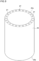
- the elastic member 25 is a tubular body which is open at both ends and in which the inner surface and the outer surface are smooth, but has a plurality of through holes 27 in an inner portion thereof which pierce the elastic member 25 from one end 25a to the other end 25b.
- each elastic member 25 has through holes 27 in the thickness-direction inner portion, the inside of each through hole 27 is a space. Consequently, in cases when heat generated by the battery cell 2 has reached the elastic member 25, the gas in the through holes 27 is heated and the resultant high-temperature gas is discharged from the through holes 27 to the one end 15a side and the other end 15b side of the elastic member 25. As a result, a fresh gas is introduced into the through holes 27 and the battery cell 2 can hence be efficiently cooled.
- the through holes 27 formed in the elastic member 25 are not particularly limited in the number, size, etc. thereof. As in the elastic member 15 shown in FIG. 4 , the through holes 27 can be variously designed in accordance with properties required of the elastic member 25 and the size of that region of the battery case 7 which is for encasing the battery cell 2 therein.
- the through holes 27 need not be always formed in a direction parallel with the longitudinal direction of the elastic member 25. In the case of forming through holes 27, the through holes 27 may be formed so as to extend from the one end 25a to the other end 25b of the elastic member 25.
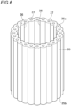
- FIG. 6 is a perspective view showing still another shape example of elastic members applicable to the assembled battery according to an embodiment of the present invention.
- the elastic member 35 has a shape formed by disposing a plurality of tubes side-by-side along the longitudinal direction thereof and bonding the adjoining surfaces to each other. Consequently, the elastic member 35 has a plurality of grooves 36 formed in the inner surface thereof like the elastic member 15 shown in FIG. 4 , and has a plurality of through holes 37 in a thickness-direction inner portion thereof which pierce the elastic member 35 form one end 35a to the other end 35b, like the elastic member 25 shown in FIG. 5 .
- Each elastic member 35 has the grooves 36 to form spaces between the elastic member 35 and the flameproof material 4 or between the elastic member 35 and the heat dissipation member 8 and further has the through holes 37. Consequently, the spaces coupled with the through holes 37 enhance the effect of discharging the heated gas to the one end 35a side and the other end 35b side of the elastic member 35, making it possible to more effectively cool the battery cell 2.
- the number and size of the through holes 37 to be formed in the elastic member 35 and the depth, etc. of the grooves 36 to be formed in the elastic member 35 can be suitably designed.
- grooves 36 or through holes 37 have been formed so as to not to extend in a direction parallel with the longitudinal direction of the elastic member 35 but to have the given angle with the parallel direction, it is possible to cool a wider area in the surface of the battery cell 2.
- the grooves 36 and the through holes 37 may have been formed either helically or curvedly.
- the battery case 7 for encasing therein any of the assembled batteries 10, 20, and 30 according to the embodiments is not particularly limited in the material and shape thereof. Besides being a polycarbonate, the material of the battery case 7 can be PP, PET, a polyamide (PA), aluminum, stainless steel (steel use stainless; SUS), or the like. The shape of the battery case 7 can be selected at will in accordance with the device, e.g., power tool, to which the assembled battery is to be applied.
- the assembled batteries 10, 20, and 30 are ones in which each battery cell 2 by itself has heat-insulating properties and which include the heat dissipation members 8 for further inhibiting heat transfer to adjoining battery cells 2 and can inhibit the occurrence of heat propagation.
- These battery cells 2 hence may not have been encased in the battery case 7.
- a plurality of battery cells 2 each covered with a flameproof material 4 and a heat dissipation member 8 may be tied up with a band or the like to configure an assembled battery and this assembled battery in such a configuration can be mounted in a device, e.g., a power tool.
- the assembled battery 10 according to this embodiment can be easily fabricated, as an assembled battery showing the effects described above, by merely covering each of battery cells 2 with a flameproof material 4 and attaching thereto a heat dissipation member 8 which is, for example, a tubular body. Since a flameproof material 4 and a heat dissipation member 8 are attached to each of the battery cells 2, a complicated design is unnecessary for the battery case 7. In the case of attaching elastic members 5, 15, 25, or 35, the assembled battery 20 or 30 can be easily fabricated in the same manner and a complicated design is unnecessary for the battery case 7.
- the flameproof materials 4 in cases when the flameproof materials 4 are sheet-shaped ones, the flameproof materials 4 each can be easily processed into a size suitable for covering the peripheral surface of a battery cell 2 regardless of the shape or size of the battery cell 2.
- the elastic members in cases when the elastic members are to be attached, the elastic members can be easily attached to various battery cells 2 without being affected by the shapes and sizes of the battery cells 2, since the elastic members have stretchability.
- the assembled batteries and battery packs according to the embodiments can be favorably used not only in power tools but in power-assisted bicycles, electric two-wheeled vehicles, electric vehicles, etc.
Landscapes
- Chemical & Material Sciences (AREA)
- Chemical Kinetics & Catalysis (AREA)
- Electrochemistry (AREA)
- General Chemical & Material Sciences (AREA)
- Engineering & Computer Science (AREA)
- Manufacturing & Machinery (AREA)
- Life Sciences & Earth Sciences (AREA)
- Biophysics (AREA)
- Battery Mounting, Suspending (AREA)
- Secondary Cells (AREA)
Abstract
Description
- The present invention relates to an assembled battery and a battery pack which are to be mounted, for example, in power tools, etc. and used as power sources for electric motors, etc.
- Power tools generally include ones which are used in the state of being connected to the so-called commercial power source and ones which have an assembled battery mounted therein that serves as a power source for an electric motor for driving. The power tools having an assembled battery mounted therein are frequently used from the point of view of the excellent handleability, etc.
- An assembled battery is a battery in which a plurality of battery cells is connected serially or in parallel. For example, battery cells are enclosed in a battery case made of, for example, a polycarbonate and united therewith, and the assembled battery is housed inside a power tool.
- Mainly used as such battery cells to be mounted in power tools are lithium-ion secondary batteries, which can have higher capacities and higher outputs than lead acid batteries and nickel-hydrogen batteries. However, in case where thermal runaway has occurred in one battery cell because of internal short-circuiting, overcharge, or the like of the battery (that is, in case of " abnormality"), it is possible that heat transfer to adjoining another battery cells might occur to cause thermal runaway to the adjoining another battery cells.
- As a measure against the occurrence of thermal runaway described above,
Patent Document 1, for example, proposes an assembled battery in which in case where abnormal heat generation has occurred, for example, because an overcurrent has flowed into a battery cell, the burning can be prevented or inhibited from spreading to adjoining battery cells. The assembled battery described inPatent Document 1 is configured of a plurality of battery cells and a block for holding the battery cells, the block being made of a metallic material and composed of a plurality of small blocks. The dimensions of the gap between the block and each battery cell are regulated. -
Patent Document 1 states that in the assembled battery described therein, which has such configuration, heat can be rapidly diffused because the block holding the battery cells is made of a metallic material. -
Patent Document 2 discloses an anti-firing material capable of reducing the risk of firing in electricity storage devices. The above anti-firing material is, for example, a porous carbonaceous material having a noncombustible gas, aqueous solvent, or noncombustible solvent adsorbed into the pores and onto the surface thereof. -
Patent Document 2 as stated above describes that in case of abnormality, when the secondary battery has released the electrolytic solution or a gaseous component, e.g., an electrolytic-solution decomposition gas, an effect can be obtained in which the gaseous component passes through the above anti-firing material and is thereby reduced in temperature. -
- Patent Document 1:
JP2014-96271A - Patent Document 2:
JP2013-187089A - However, in the assembled battery described in
Patent Document 1, since the block made of a metallic material is composed of two, vertically separated parts and has a heat insulator disposed between the two parts, it is difficult to efficiently dissipate heat generated from one battery. - Furthermore, the assembled battery described in
Patent Document 1 necessitates a plurality of blocks and the blocks need to be designed in accordance with the electronic appliance, power tool, or the like in which the assembled battery is to be mounted, since the gaps between the blocks and the battery cells are varied. There is hence a problem in that the design of the blocks and fabrication of the assembled battery are complicated. - With respect to
Patent Document 2, the anti-firing material, although effective against the evolution of a gaseous component from a secondary battery in case of abnormality, is unable to lower the temperature of the batteries themselves in cases when the battery cells which have been fabricated into an assembled battery are subjected to charge/discharge cycling (i.e., "during ordinary use") and in case of abnormality. - The present invention is made in view of the aforementioned problems, and an object of the invention is to provide an assembled battery and a battery pack which are easy to design and fabricate and in which during ordinary use and in case of abnormality, heat transfer between battery cells can be inhibited and the battery cells can be efficiently cooled to inhibit the occurrence of thermal runaway.
- The object of the present invention is accomplished with the following configuration [1] regarding an assembled battery.
- [1] An assembled battery in which a plurality of battery cells is connected serially or in parallel, the battery cells each having an electrode surface having an electrode and a peripheral surface orthogonal to the electrode surface and being disposed such that the peripheral surfaces face each other,
- the assembled battery including
- the battery cells,
- a flameproof material covering the peripheral surface of the battery cells, and
- a heat dissipation member covering the peripheral surface of the battery cells which is covered with the flameproof material.
- [2] The assembled battery according to [1] wherein the heat dissipation member is a tubular body which is open at both ends.
- [3] The assembled battery according to [1] wherein the heat dissipation member is a sheet-shaped heat dissipation material wrapped around the peripheral surface of the battery cells which is covered with the flameproof material.
- [4] The assembled battery according to any one of [1] to [3] wherein the heat dissipation member is made of at least one material selected from among metals, carbon, and ceramics.
- [5] The assembled battery according to any one of [1] to [4] wherein the flameproof material contains organic fibers and/or inorganic fibers.
- [6] The assembled battery according to any one of [1] to [5] which includes an elastic member disposed between the flameproof material and the heat dissipation member, the elastic member covering at least a part of the peripheral surface of the battery cells which is covered with the flameproof material and pressing the battery cells.
- [7] The assembled battery according to any one of [1] to [5] which includes an elastic member provided to at least a part of the peripheral surface of the battery cells which is covered with both the flameproof material and the heat dissipation member, the elastic member covering the peripheral surface along a peripheral direction and pressing the battery cells.
- [8] The assembled battery according to [6] or [7] wherein the elastic member is made of a rubber or an elastomer.
- [9] The assembled battery according to any one of [6] to [8] wherein the elastic member is a tubular body which is open at both ends.
- [10] The assembled battery according to [9] wherein the elastic member has a plurality of grooves extending in an inner surface of the tubular body from one end to the other end of the tubular body.
- [11] The assembled battery according to [9] or [10] wherein the elastic member has a plurality of through holes piercing the tubular body from one end to the other end thereof.
The object of the present invention is accomplished with the following configuration [12] regarding a battery pack. - [12] A battery pack obtained by encasing the assembled battery according to any one of [1] to [11] in a battery case.
- Since the assembled battery of the present invention includes a flameproof material covering the peripheral surface of each battery cell, the transfer of heat between the battery cells can be inhibited during ordinary use and in case of abnormality. Since the assembled battery of the present invention includes a heat dissipation member covering the peripheral surface of the flameproof material, heat generated from each battery cell can be efficiently radiated to the outside. Furthermore, since the assembled battery of the present invention can be fabricated by merely attaching the flameproof material and the heat dissipation member to the peripheral surface of each battery cell, there is no need of changing the design of the battery case in accordance with the kind of the battery cells and fabrication of the assembled battery requires no complicated operation.
- Since the battery pack of the present invention includes the assembled battery encased, not only the transfer of heat between the battery cells can be inhibited and the propagation of thermal runaway can be prevented, but also this battery pack can be easily fabricated.
-
-
FIG. 1 is a cross-sectional view schematically illustrating a battery pack containing an assembled battery according to a first embodiment of the present invention. -
FIG. 2 is a cross-sectional view schematically illustrating a battery pack containing an assembled battery according to a second embodiment of the present invention. -
FIG. 3 is a cross-sectional view schematically illustrating a battery pack containing an assembled battery according to a third embodiment of the present invention. -
FIG. 4 is a perspective view showing a shape example of elastic members applicable to an assembled battery according to an embodiment of the present invention. -
FIG. 5 is a perspective view showing another shape example of elastic members applicable to the assembled battery according to an embodiment of the present invention. -
FIG. 6 is a perspective view showing still another shape example of elastic members applicable to the assembled battery according to an embodiment of the present invention. - The present inventor diligently made investigations in order to provide an assembled battery in which during ordinary use and in case of abnormality, heat transfer between the battery cells can be inhibited and the battery cells can be efficiently cooled to inhibit the occurrence of thermal runaway.
- As a result, the inventor has discovered that the problems described above can be eliminated by covering the peripheral surface of each battery cell with a flameproof material and covering the peripheral surface thereof with a heat dissipation member.
- Embodiments of the present invention are described in detail below while referring to the drawings. The present invention is not limited to the following embodiments, and can be modified at will so long as the modifications do not depart from the spirit of the invention.
-
FIG. 1 is a cross-sectional view schematically illustrating a battery pack containing an assembled battery according to a first embodiment of the present invention. Thebattery pack 1 is one obtained by encasing an assembledbattery 10 according to a first embodiment, which is described in detail below, in abattery case 7 made of, for example, a resin. - The assembled battery according to a first embodiment of the present invention is described in detail below.
- Each
battery cell 2 has anelectrode surface 2a having anelectrode 3 and aperipheral surface 2b that is a surface orthogonal to theelectrode surface 2a. Thebattery cells 2 have been disposed such that theperipheral surfaces 2b thereof face each other, and are connected serially or in parallel, with theelectrodes 3 and a connector (not shown), etc. interposed therebetween. - The
peripheral surface 2b of eachbattery cell 2 is covered with aflameproof material 4 and the peripheral surface of theflameproof material 4 is covered with aheat dissipation member 8, thereby configuring the assembledbattery 10. Theheat dissipation member 8 is, for example, a tubular body which is open at both ends, and covers the peripheral surface of thebattery cell 2 andflameproof material 4. In this embodiment, the expression "both ends of the heat dissipation member 8 (tubular body)" means one longitudinal-direction (top-bottom direction inFIG. 1 ) end of theheat dissipation member 8 and the other end thereof, namely, the open ends of the tubular body. - In the assembled
battery 10 having such configuration, since theperipheral surface 2b of eachbattery cell 2 is covered with theflameproof material 4, heat generated from thebattery cell 2 during ordinary use can be inhibited from being transferred to the periphery. Meanwhile, even in a case where thermal runaway has occurred in one of the battery cells in case of abnormality, heat transfer to the periphery is inhibited and the other battery cell, which adjoins said one battery cell, can be inhibited from receiving the heat, making it possible to prevent the thermal runaway from propagating. - The
heat dissipation member 8 further covering the peripheral surface of thebattery cell 2 andflameproof material 4 is made of a material having excellent thermal conductivity, as will be described later. Because of this, in cases when some of the heat was unable to be inhibited by theflameproof material 4 from being transferred and has reached theheat dissipation member 8, then the heat spreads in plane directions of thedissipation member 8 and is radiated to both end sides of theheat dissipation member 8. Thebattery cell 2 can hence be efficiently cooled. - Incidentally, when thermal runaway occurs in a battery cell in case of abnormality, a gas is evolved within this battery to elevate the internal pressure and thus cause a deformation of the battery cell. This deformation, when large, may cause breakage of the case.
- In the assembled
battery 10 according to the first embodiment, theheat dissipation member 8 is a tubular body as stated above, and is made of a material such as, for example, a metal or carbon, and has substantially no stretchability. Because of this, in cases when the gap between theheat dissipation member 8 and thebattery cell 2 andflameproof material 4 is small, an effect can be obtained in which if thebattery cell 2 deforms in case of abnormality, theheat dissipation member 8 inhibits thebattery cell 2 from deforming. Thebattery case 7 can hence be inhibited from breaking. - If the
battery cell 2 has heated up to an even higher temperature and exploded due to an increase in internal pressure, the covering of thebattery cell 2 with theheat dissipation member 8 makes it possible to avoid a trouble, for example, that fragments of thebattery cell 2, an organic electrolytic liquid present in thebattery cell 2, etc. reachother battery cells 2 to exert an adverse influence. - In this embodiment, the
battery cells 2 may be prismatic or round. - Each
flameproof material 4 preferably covers all of the peripheral surface of thebattery cell 2. However, a part of the peripheral surface may be uncovered according to need, so long as theflameproof material 4 can inhibit the propagation of thermal runaway described above. - Each
heat dissipation member 8 also preferably covers all of the peripheral surface of thebattery cell 2 covered with theflameproof material 4. However, a part of the peripheral surface may be uncovered according to need, so long as theheat dissipation member 8 can have the heat dissipation effect described above. - In the assembled
battery 10 according to the first embodiment described above, theheat dissipation members 8 were each a tubular body open at both ends. However, theheat dissipation members 8 are not limited to tubular bodies. For example, a sheet-shaped heat dissipation material may be used and wrapped around the outer surface of abattery cell 2 covered with aflameproof material 4 to form aheat dissipation member 8. - In the case of using a heat dissipation member thus formed, the effect of inhibiting the
battery cell 2 from deforming is lower than in the case of using the tubularheat dissipation member 8. However, since battery cells slightly deform during ordinary use, the heat dissipation member formed by wrapping a sheet-shaped heat dissipation material around the peripheral surface of theflameproof material 4 can flexibly cope with the deformations during ordinary use. - Even with a sheet-shaped heat dissipation material, a tubular
heat dissipation member 8 can be easily produced by wrapping the sheet around the outer surface of theflameproof material 4 and then fixing the free end of the wrapped sheet to a part of the wrapped sheet. -
FIG. 2 is a cross-sectional view schematically illustrating a battery pack containing an assembled battery according to a second embodiment of the present invention. InFIGs. 2 and3 , which show the second and third embodiments described below, parts or portions that are identical with or equal to those in the first embodiment are designated by like numerals, and explanations thereon are omitted or simplified. - In the second embodiment, the assembled
battery 20 includeselastic members 5 each disposed between aflameproof material 4 and aheat dissipation member 8 over theperipheral surface 2b of abattery cell 2. Like theheat dissipation member 8, theelastic member 5 is, for example, a tubular body which is open at both ends. Theelastic member 5 covers the peripheral surface of thebattery cell 2 andflameproof material 4 along the peripheral direction and presses the battery cell. - In the second embodiment, which has such configuration, the
elastic members 5, which press thebattery cells 2, have both the effect of inhibiting thebattery cells 2 from deforming and the effect of absorbing deformations of thebattery cells 2. That is, when abattery cell 2 deforms in case of abnormality, theheat dissipation member 8 flexibly deforms in accordance with the deformation of thebattery cell 2 while inhibiting the deformation of thebattery cell 2. Because of this, even when the heat dissipation member is one formed from a sheet-shaped heat dissipation material, theelastic member 5 can absorb the deformations of thebattery cell 2 to inhibit thebattery case 7 from breaking. - Furthermore, during ordinary use, the
elastic member 5 disposed between theflameproof material 4 and theheat dissipation member 8 can absorb slight deformations of thebattery cell 2 to prevent a pressure from being unnecessarily applied to adjoiningbattery cells 2. -
FIG. 3 is a cross-sectional view schematically illustrating a battery pack containing an assembled battery according to a third embodiment of the present invention. - In the third embodiment, the assembled
battery 30 includeselastic members 5 each disposed on the outer side of aflameproof material 4 and aheat dissipation member 8 over theperipheral surface 2b of abattery cell 2. Theelastic member 5 is, for example, a tubular body which is open at both ends, as in the second embodiment. Theelastic member 5 covers, along the peripheral direction, the peripheral surface of thebattery cell 2 covered with both theflameproof material 4 and theheat dissipation member 8 and presses the battery cell. - The third embodiment, which has such configuration, is especially effective, for example, when heat dissipation members formed from sheet-shaped heat dissipation materials are used. As stated above, in cases when a heat dissipation member formed from a sheet-shaped heat dissipation material is used on the peripheral surface of a
battery cell 2 covered with aflameproof material 4, then the effect of inhibiting thebattery cell 2 from deforming is lessened. In this embodiment, however, since anelastic member 5 has been further disposed on the peripheral surface of the heat dissipation member, it is possible, during ordinary use and in case of abnormality, to absorb deformations of thebattery cell 2 while inhibiting thebattery cell 2 from deforming, thereby inhibiting thebattery case 7 from breaking. - Materials for forming the
elastic members 5 will be described later. Theelastic members 5 may be made of a material having heat-insulating properties, like theflameproof materials 4. Hence, by disposing suchelastic members 5 on the peripheral surfaces of the heat dissipation members, a higher heat-insulating effect can be obtained. - In the second and third embodiments, which include
elastic members 5, eachelastic member 5 need not cover all of the peripheral surface of theflameproof material 4 orheat dissipation member 8, and may be one which can be expected to have the effects ofelastic members 5 described above. For example, eachelastic member 5 may be one which covers only a part of the peripheral surface so long as the assembled battery has been configured so that theelastic member 5 covers the peripheral surface along the peripheral direction and presses thebattery cell 2. - Next, the
flameproof materials 4,heat dissipation members 8, andelastic members 5 which constitute the assembled batteries according to the embodiments are described in detail. - The
flameproof materials 4 to be used in the assembledbatteries flameproof materials 4 should have heat-insulating properties, these materials are selected from among materials having high heat-insulating performance. - Examples of the inorganic fibers include silica-alumina fibers, alumina fibers, silica fibers, rock wool, alkaline-earth silicate fibers, glass fibers, zirconia fibers, and potassium titanate whisker fibers. These inorganic fibers are preferred from the standpoints of heat resistance, strength, availability, etc. Inorganic fibers of one kind may be used alone, or two or more kinds of inorganic fibers may be used in combination. Especially preferred of those inorganic fibers from the standpoint of handleability are silica-alumina fibers, alumina fibers, silica fibers, rock wool, alkaline-earth silicate fibers, and glass fibers.
- The cross-sectional shape of the inorganic fibers is not particularly limited, and examples thereof include a circular cross-section, a flat cross-section, a hollow cross-section, a polygonal cross-section, and a core cross-section. Of these, fibers having an unusual cross-section such as a hollow, flat, or polygonal cross-section are suitable for use because such fibers slightly improve the heat-insulating properties.
- A preferred lower limit of the average fiber length of the inorganic fibers is 0.1 mm, and a more preferred lower limit thereof is 0.5 mm. Meanwhile, a preferred upper limit of the average fiber length of the inorganic fibers is 50 mm, and a more preferred upper limit thereof is 10 mm. In case where the average fiber length of the inorganic fibers is less than 0.1 mm, the inorganic fibers are less apt to be intertwined with each other and this may reduce the mechanical strength of the
flameproof material 4. Meanwhile, in case where the average fiber length thereof exceeds 50 mm, the inorganic fibers, although having a reinforcing effect, cannot be tightly intertwined with each other, or the individual inorganic fibers separately become round and this is prone to form continuous voids and may hence result in a decrease in heat-insulating property. - A preferred lower limit of the average fiber diameter of the inorganic fibers is 1 µm, a more preferred lower limit thereof is 2 µm, and a still more preferred lower limit thereof is 3 µm. Meanwhile, a preferred upper limit of the average fiber diameter of the inorganic fibers is 15 µm, and a more preferred upper limit thereof is 10 µm. In case where the average fiber diameter of the inorganic fibers is less than 1 µm, the inorganic fibers themselves are likely to have reduced mechanical strength. From the standpoint of influences on human health, the average fiber diameter of the inorganic fibers is preferably 3 µm or larger. Meanwhile, in case where the average fiber diameter of the inorganic fibers is larger than 15 µm, there is a possibility that heat transfer by the inorganic fibers as a solid medium might be enhanced to result in a decrease in heat-insulating property and that the flameproof material might be deteriorated in shapability and strength.
- As the organic fibers, fibers made of heat-curing resins and thermoplastic resins can be selected. For example, use can be made of synthetic fibers made of modified poly(ethylene terephthalate) (PET), polyethylene (PE), polypropylene, polyesters, nylons, poly(butylene terephthalate), and the like.
- The kinds, structures, etc. of synthetic fibers usable in the embodiments are explained in greater detail below.
- Vinylon: fibers made of a long-chain synthetic polymer including at least 65 mass% vinyl alcohol units.
- Vinylal: fibers made of a long-chain synthetic poly(vinyl alcohol) polymer having a different degree of acetalization.
- Poly(vinyl chloride) (chlorofiber): fibers made of a long-chain synthetic polymer including vinyl chloride units as a main component.
- Vinylidene (poly(vinylidene chloride), chlorofiber): fibers made of a long-chain synthetic polymer including vinylidene chloride units (-CH2-CCl2-) as a main component.
- Acrylic: fibers made of a long-chain synthetic polymer including at least 85 mass% repeating units of acrylonitrile group.
- Modacrylic: fibers made of a long-chain synthetic polymer including repeating units of acrylonitrile group in an amount of 35 mass% or larger but less than 85 mass%.
- Nylon (polyamide): fibers made of a long-chain synthetic polymer in which 85% or more of repeating amide bonds are bonded to aliphatic or alicyclic units.
- Aramid: fibers made of a long-chain synthetic polymer in which 85 mass% or more of amide or imide bonds are each directly bonded to two benzene rings and the number of imide bonds, if any, does not exceed the number of amide bonds.
- Polyester: fibers made of a long-chain synthetic polymer including at least 85 mass% units of an ester of terephthalic acid with a dihydric alcohol.
- Poly(ethylene terephthalate) (PET): fibers made of a long-chain synthetic polymer including at least 85 mass% units of an ester of terephthalic acid with ethylene glycol.
- Poly(trimethylene terephthalate) (PTT): fibers made of a long-chain synthetic polymer including at least 85 mass% units of an ester of terephthalic acid with 1,3-propanediol.
- Poly(butylene terephthalate) (PBT): fibers made of a long-chain synthetic polymer including at least 85 mass% units of an ester of terephthalic acid with 1,4-butanediol.
- Polyethylene (PE): fibers made of a long-chain synthetic polymer formed from a saturated aliphatic hydrocarbon and having no substituents.
- Polypropylene (PP): fibers made of a long-chain synthetic polymer which is a polymer formed from a saturated aliphatic hydrocarbon and having a methyl side chain bonded to one of every two carbon atoms and which has stereoregularity and has no other substituents.
- Polyurethane (elastane): fibers made of a long-chain synthetic polymer which includes 85 mass% or more polyurethane segment and which, when elongated three times the tension-free length, rapidly recovers the original length upon release from the tension.
- Poly (lactic acid) (polylactide): fibers made of a long-chain synthetic polymer including lactic ester units in an amount of 50 mass% or larger
- Preferred ranges of the average fiber length and average fiber diameter of the organic fibers are the same as those of the inorganic fibers.
- The inorganic particles are preferably ones made of a compound having heat resistance. For example, a metal oxide can be used.
- Specific examples of the metal oxide include silica (SiO2), alumina (Al2O3), mullite (Al6O13Si2), zirconia (ZrO2), magnesia (MgO), and titania (TiO2). However, the metal oxide is not limited to these. Besides those metal oxides, preferred examples of the inorganic particles include boron nitride (BN) and boron carbide (B4C).
- As materials for the heat dissipation members to be used in the assembled
batteries battery cell 2 and has reached theheat dissipation member 8 is diffused in plane directions of theheat dissipation member 8 and radiated to both end sides of theheat dissipation member 8. - Such materials preferably have heat transfer coefficients of, for example, 10 (W/m·K) or higher. Specifically, it is preferred to select at least one material from among metals, carbon, and ceramics.
- Examples of the metals include stainless steel, aluminum or aluminum alloys, and copper or copper alloys.
- Examples of the ceramics include SiC and AlN.
- As the
elastic members 5 to be used in the assembledbatteries elastic members 5 to deform flexibly in accordance with deformations of thebattery cells 2 and stretchability which enables theelastic members 5 to press thebattery cells 2 after having been attached to the peripheral surfaces of theflameproof materials 4 orheat dissipation members 8 and that preferably have heat-insulating properties. As suchelastic members 5, a rubber or an elastomer can, for example, be used. - The
elastic members 5 shown inFIG. 2 andFIG. 3 are each a tubular body which is open at both ends and in which the outer surface and the inner surface are smooth. However, the shape of theelastic members 5 is not limited to that shown inFIG. 2 andFIG. 3 . -
FIG. 4 is a perspective view showing a shape example of elastic members applicable to an assembled battery according to an embodiment of the present invention. Elastic members having the shapes shown below can all be used in place of theelastic members 5 of the assembledbattery 20 shown inFIG. 2 or the assembledbattery 30 shown inFIG. 3 . The effects, etc. of elastic members having the various shapes shown below are hence explained on the assumption that the elastic members have been applied to the assembledbattery - As
FIG. 4 shows, the inner surface of theelastic member 15, which is a tubular body, has a plurality ofgrooves 16 formed therein which extend from oneend 15a to theother end 15b of theelastic member 15. In this embodiment, the terms "oneend 15a" and "theother end 15b" for the elastic member 5 (tubular body) respectively mean one longitudinal-direction (top-bottom direction inFIG. 2 ) end and the other longitudinal-direction end of theelastic member 5. That is, those terms mean the open ends of the tubular body. - In cases when
elastic members 15 thus configured are used in the assembledbattery 20 shown inFIG. 2 or in the assembledbattery 30 shown inFIG. 3 , it is possible to obtain the same effects as in the second embodiment or the third embodiment, respectively. - Furthermore, since the
elastic member 15 hasgrooves 16 in the inner surface thereof, spaces are formed between theelastic member 15 and theflameproof material 4 or between theelastic member 15 and theheat dissipation member 8. Because of this, in cases when heat has reached theelastic member 15, the gas in the spaces is heated and the high-temperature gas is discharged from the spaces to the oneend 15a side and theother end 15b side of theelastic member 15. As a result, a fresh gas is introduced into the spaces and thebattery cell 2 can hence be effectively cooled. - The
grooves 16 formed in theelastic member 15 are not particularly limited in the number, depth, peripheral-direction width, etc. thereof. By changing the number, depth, and peripheral-direction width of thegrooves 16, the elasticity, stretchability, etc. of theelastic member 15 can be changed. It is hence possible to variously design thegrooves 16 in accordance with required properties and the size of that region of thebattery case 7 which is for encasing thebattery cell 2 therein. - The
grooves 16 need not be always formed in a direction parallel with the longitudinal direction of theelastic member 15. However, from the standpoint of preventing the heat of thebattery cell 2 from being transferred to adjoiningbattery cells 2, it is preferred to discharge the heated gas to theelectrode surface 2a side of thebattery cell 2 and to the side where the surface facing theelectrode surface 2a is present. Consequently, in the case of forminggrooves 16, thegrooves 16 may be formed so as to extend from the oneend 15a to theother end 15b of theelastic member 15. - In cases when
grooves 16 have been formed so as not extend in a direction parallel with the longitudinal direction of theelastic member 15 but to have a given angle with the parallel direction, it is possible to cool a wider area in the surface of thebattery cell 2. Thegrooves 16 may have been formed either helically or curvedly. - The given angle is preferably larger than 0° with respect to the parallel direction. Meanwhile, the given angle is preferably 45° or less because the heated high-temperature gas can be efficiently discharged, and is more preferably 30° or less.
-
FIG. 5 is a perspective view showing another shape example of elastic members applicable to the assembled battery according to an embodiment of the present invention. AsFIG. 5 shows, theelastic member 25 is a tubular body which is open at both ends and in which the inner surface and the outer surface are smooth, but has a plurality of throughholes 27 in an inner portion thereof which pierce theelastic member 25 from oneend 25a to theother end 25b. - Also, in an assembled battery employing
elastic members 25 thus configured, it is possible to obtain the same effects as in the case where theelastic members 5 and theelastic members 15 are used. Since eachelastic member 25 has throughholes 27 in the thickness-direction inner portion, the inside of each throughhole 27 is a space. Consequently, in cases when heat generated by thebattery cell 2 has reached theelastic member 25, the gas in the throughholes 27 is heated and the resultant high-temperature gas is discharged from the throughholes 27 to the oneend 15a side and theother end 15b side of theelastic member 25. As a result, a fresh gas is introduced into the throughholes 27 and thebattery cell 2 can hence be efficiently cooled. - The through holes 27 formed in the
elastic member 25 are not particularly limited in the number, size, etc. thereof. As in theelastic member 15 shown inFIG. 4 , the throughholes 27 can be variously designed in accordance with properties required of theelastic member 25 and the size of that region of thebattery case 7 which is for encasing thebattery cell 2 therein. - The through holes 27 need not be always formed in a direction parallel with the longitudinal direction of the
elastic member 25. In the case of forming throughholes 27, the throughholes 27 may be formed so as to extend from the oneend 25a to theother end 25b of theelastic member 25. - In cases when through
holes 27 have been formed so as not to extend in a direction parallel with the longitudinal direction of theelastic member 25 but to have the given angle with the parallel direction, it is possible to cool a wider area in the surface of thebattery cell 2. Note that the throughholes 27 may have been formed either helically or curvedly. -
FIG. 6 is a perspective view showing still another shape example of elastic members applicable to the assembled battery according to an embodiment of the present invention. AsFIG. 6 shows, theelastic member 35 has a shape formed by disposing a plurality of tubes side-by-side along the longitudinal direction thereof and bonding the adjoining surfaces to each other. Consequently, theelastic member 35 has a plurality ofgrooves 36 formed in the inner surface thereof like theelastic member 15 shown inFIG. 4 , and has a plurality of throughholes 37 in a thickness-direction inner portion thereof which pierce theelastic member 35 form oneend 35a to theother end 35b, like theelastic member 25 shown inFIG. 5 . - Also, in an assembled battery employing
elastic members 35 thus configured, it is possible to obtain the same effects as in the case where theelastic members elastic member 35 has thegrooves 36 to form spaces between theelastic member 35 and theflameproof material 4 or between theelastic member 35 and theheat dissipation member 8 and further has the through holes 37. Consequently, the spaces coupled with the throughholes 37 enhance the effect of discharging the heated gas to the oneend 35a side and theother end 35b side of theelastic member 35, making it possible to more effectively cool thebattery cell 2. - The number and size of the through
holes 37 to be formed in theelastic member 35 and the depth, etc. of thegrooves 36 to be formed in theelastic member 35 can be suitably designed. - As in the case of the
elastic member 15 and theelastic member 25, in cases whengrooves 36 or throughholes 37 have been formed so as to not to extend in a direction parallel with the longitudinal direction of theelastic member 35 but to have the given angle with the parallel direction, it is possible to cool a wider area in the surface of thebattery cell 2. Thegrooves 36 and the throughholes 37 may have been formed either helically or curvedly. - The
battery case 7 for encasing therein any of the assembledbatteries battery case 7 can be PP, PET, a polyamide (PA), aluminum, stainless steel (steel use stainless; SUS), or the like. The shape of thebattery case 7 can be selected at will in accordance with the device, e.g., power tool, to which the assembled battery is to be applied. - Incidentally, the assembled
batteries battery cell 2 by itself has heat-insulating properties and which include theheat dissipation members 8 for further inhibiting heat transfer to adjoiningbattery cells 2 and can inhibit the occurrence of heat propagation. Thesebattery cells 2 hence may not have been encased in thebattery case 7. For example, a plurality ofbattery cells 2 each covered with aflameproof material 4 and aheat dissipation member 8 may be tied up with a band or the like to configure an assembled battery and this assembled battery in such a configuration can be mounted in a device, e.g., a power tool. - The assembled
battery 10 according to this embodiment can be easily fabricated, as an assembled battery showing the effects described above, by merely covering each ofbattery cells 2 with aflameproof material 4 and attaching thereto aheat dissipation member 8 which is, for example, a tubular body. Since aflameproof material 4 and aheat dissipation member 8 are attached to each of thebattery cells 2, a complicated design is unnecessary for thebattery case 7. In the case of attachingelastic members battery battery case 7. - In the embodiments, in cases when the
flameproof materials 4 are sheet-shaped ones, theflameproof materials 4 each can be easily processed into a size suitable for covering the peripheral surface of abattery cell 2 regardless of the shape or size of thebattery cell 2. In cases when the elastic members are to be attached, the elastic members can be easily attached tovarious battery cells 2 without being affected by the shapes and sizes of thebattery cells 2, since the elastic members have stretchability. - The assembled batteries and battery packs according to the embodiments can be favorably used not only in power tools but in power-assisted bicycles, electric two-wheeled vehicles, electric vehicles, etc.
- Various embodiments were explained above while referring to the drawings, but it is a matter of course that the present invention is not limited to those examples. It is apparent that a person skilled in the art can conceive of variously modified or changed examples within the scope of the claims, and these examples are, of course, considered to be within the technical range of the present invention. The constituent elements in the embodiments described above may be combined at will so long as the combinations do not depart from the spirit of the invention.
- This application is based on a
Japanese patent application filed on February 1, 2021 (Application No. 2021-014632 -
- 1: Battery pack
- 2: Battery cell
- 2a: Electrode surface
- 3: Electrode
- 4: Flameproof material
- 5, 15, 25, 35: Elastic member
- 7: Battery case
- 8: Heat dissipation member
- 10, 20, 30: Assembled battery
- 16, 36: Groove
- 27, 37: Through hole
Claims (12)
- An assembled battery in which a plurality of battery cells is connected serially or in parallel, the battery cells each having an electrode surface having an electrode and a peripheral surface orthogonal to the electrode surface and being disposed such that the peripheral surfaces face each other,the assembled battery comprisingthe battery cells,a flameproof material covering the peripheral surface of the battery cells, anda heat dissipation member covering the peripheral surface of the battery cells which is covered with the flameproof material.
- The assembled battery according to claim 1, wherein the heat dissipation member is a tubular body which is open at both ends.
- The assembled battery according to claim 1, wherein the heat dissipation member is a sheet-shaped heat dissipation material wrapped around the peripheral surface of the battery cells which is covered with the flameproof material.
- The assembled battery according to any one of claims 1 to 3, wherein the heat dissipation member is made of at least one material selected from among metals, carbon, and ceramics.
- The assembled battery according to any one of claims 1 to 4, wherein the flameproof material contains organic fibers and/or inorganic fibers.
- The assembled battery according to any one of claims 1 to 5, which includes an elastic member disposed between the flameproof material and the heat dissipation member, the elastic member covering at least a part of the peripheral surface of the battery cells which is covered with the flameproof material and pressing the battery cells.
- The assembled battery according to any one of claims 1 to 5, which includes an elastic member provided to at least a part of the peripheral surface of the battery cells which is covered with both the flameproof material and the heat dissipation member, the elastic member covering the peripheral surface along a peripheral direction and pressing the battery cells.
- The assembled battery according to claim 6 or 7, wherein the elastic member is made of a rubber or an elastomer.
- The assembled battery according to any one of claims 6 to 8, wherein the elastic member is a tubular body which is open at both ends.
- The assembled battery according to claim 9, wherein the elastic member has a plurality of grooves extending in an inner surface of the tubular body from one end to the other end of the tubular body.
- The assembled battery according to claim 9 or 10, wherein the elastic member has a plurality of through holes piercing the tubular body from one end to the other end of the tubular body.
- A battery pack in which the assembled battery according to any one of claims 1 to 11 is encased in a battery case.
Applications Claiming Priority (2)
| Application Number | Priority Date | Filing Date | Title |
|---|---|---|---|
| JP2021014632A JP7089076B1 (en) | 2021-02-01 | 2021-02-01 | Batteries and battery packs |
| PCT/JP2022/003686 WO2022163856A1 (en) | 2021-02-01 | 2022-01-31 | Assembled battery and battery pack |
Publications (3)
| Publication Number | Publication Date |
|---|---|
| EP4287372A1 true EP4287372A1 (en) | 2023-12-06 |
| EP4287372A4 EP4287372A4 (en) | 2025-01-08 |
| EP4287372B1 EP4287372B1 (en) | 2026-03-11 |
Family
ID=82100048
Family Applications (1)
| Application Number | Title | Priority Date | Filing Date |
|---|---|---|---|
| EP22746075.5A Active EP4287372B1 (en) | 2021-02-01 | 2022-01-31 | Assembled battery and battery pack |
Country Status (5)
| Country | Link |
|---|---|
| US (1) | US20240128566A1 (en) |
| EP (1) | EP4287372B1 (en) |
| JP (1) | JP7089076B1 (en) |
| CN (1) | CN116964838A (en) |
| WO (1) | WO2022163856A1 (en) |
Families Citing this family (1)
| Publication number | Priority date | Publication date | Assignee | Title |
|---|---|---|---|---|
| KR20250039165A (en) * | 2023-09-13 | 2025-03-20 | 주식회사 아모그린텍 | Battery thermal runaway delay and flame retardant pad and battery pack comprising the same |
Family Cites Families (12)
| Publication number | Priority date | Publication date | Assignee | Title |
|---|---|---|---|---|
| JP5136078B2 (en) | 2008-01-22 | 2013-02-06 | 豊田合成株式会社 | Battery assembly |
| JP5966457B2 (en) | 2012-03-08 | 2016-08-10 | 栗田工業株式会社 | Ignition prevention material for electricity storage device, ignition prevention system including this ignition prevention material, and electricity storage system using this ignition prevention system |
| JP2014096271A (en) | 2012-11-09 | 2014-05-22 | Panasonic Corp | Battery pack |
| JP2019053816A (en) | 2016-01-28 | 2019-04-04 | 三洋電機株式会社 | Battery pack |
| JP6885791B2 (en) | 2017-06-05 | 2021-06-16 | 積水化学工業株式会社 | Thermal runaway prevention sheet |
| JP7074455B2 (en) | 2017-10-31 | 2022-05-24 | イビデン株式会社 | Insulation sheet for assembled battery and assembled battery |
| US12080898B2 (en) * | 2017-12-22 | 2024-09-03 | Cummins Inc. | Thermal runaway mitigation system for high capacity energy cell |
| WO2019161574A1 (en) * | 2018-02-26 | 2019-08-29 | 中国电力科学研究院有限公司 | Safety prevention and control method and device for battery energy storage module |
| JP7326250B2 (en) | 2018-03-30 | 2023-08-15 | 三洋電機株式会社 | Power supply device and electric vehicle and power storage device equipped with this power supply device |
| JP7203568B2 (en) | 2018-10-31 | 2023-01-13 | イビデン株式会社 | Heat transfer suppression sheet for assembled battery, sheet structure, and assembled battery |
| JP7123014B2 (en) | 2019-07-16 | 2022-08-22 | 日鉄テックスエンジ株式会社 | Dross detection system |
| CN210467919U (en) * | 2019-09-06 | 2020-05-05 | 昆山富士锦电子有限公司 | Battery core module |
-
2021
- 2021-02-01 JP JP2021014632A patent/JP7089076B1/en active Active
-
2022
- 2022-01-31 EP EP22746075.5A patent/EP4287372B1/en active Active
- 2022-01-31 WO PCT/JP2022/003686 patent/WO2022163856A1/en not_active Ceased
- 2022-01-31 US US18/275,098 patent/US20240128566A1/en active Pending
- 2022-01-31 CN CN202280012503.3A patent/CN116964838A/en active Pending
Also Published As
| Publication number | Publication date |
|---|---|
| JP2022117873A (en) | 2022-08-12 |
| EP4287372B1 (en) | 2026-03-11 |
| CN116964838A (en) | 2023-10-27 |
| WO2022163856A1 (en) | 2022-08-04 |
| JP7089076B1 (en) | 2022-06-21 |
| EP4287372A4 (en) | 2025-01-08 |
| US20240128566A1 (en) | 2024-04-18 |
Similar Documents
| Publication | Publication Date | Title |
|---|---|---|
| EP4287371A1 (en) | Flameproof sheet, assembled battery, and battery pack | |
| KR102949547B1 (en) | A battery pack with thermal propagation prevention structure between battery modules | |
| JP7441643B2 (en) | Cell unit, battery including the same, and battery manufacturing method | |
| KR102311508B1 (en) | Battery module including a housing floor with integrated cooling | |
| EP3349268B1 (en) | Cell assembly having cushion member | |
| EP3553843A1 (en) | Secondary battery module | |
| EP3852185A1 (en) | Power supply device | |
| JP7273237B2 (en) | Flame-retardant sheets, assembled batteries and battery packs | |
| US20100136404A1 (en) | Thermal barrier structure for containing thermal runaway propagation within a battery pack | |
| CN107658393A (en) | A kind of battery pack based on honeycomb accumulation | |
| KR101757382B1 (en) | Cooling member of improved cooling performance and battery module comprising the same | |
| KR102772374B1 (en) | Energy storage system | |
| EP4287373A1 (en) | Battery assembly, and battery pack | |
| US20130202939A1 (en) | Heat control pouch for battery cell module and battery cell module having the same | |
| JP2009176464A (en) | Battery assembly | |
| KR102213758B1 (en) | High power Lithium Ion Battery at elevated temperature with composite heat dissipated material | |
| US20240128566A1 (en) | Assembled battery and battery pack | |
| KR20190138358A (en) | Battery Module | |
| KR102894088B1 (en) | Battery module and battery pack including the same | |
| WO2021106444A1 (en) | Heat conductive member and battery provided with same | |
| KR101976588B1 (en) | Assembly type heat dissipation cartridge and battery pack for electric vehicle using the same | |
| JP2011113641A (en) | Battery module | |
| KR20220132374A (en) | Secondary battery module and secondary battery pack including same | |
| US12362413B2 (en) | Battery cell, and battery module, battery pack and vehicle including the same | |
| CN116171502A (en) | Battery pack |
Legal Events
| Date | Code | Title | Description |
|---|---|---|---|
| STAA | Information on the status of an ep patent application or granted ep patent |
Free format text: STATUS: THE INTERNATIONAL PUBLICATION HAS BEEN MADE |
|
| PUAI | Public reference made under article 153(3) epc to a published international application that has entered the european phase |
Free format text: ORIGINAL CODE: 0009012 |
|
| STAA | Information on the status of an ep patent application or granted ep patent |
Free format text: STATUS: REQUEST FOR EXAMINATION WAS MADE |
|
| 17P | Request for examination filed |
Effective date: 20230831 |
|
| AK | Designated contracting states |
Kind code of ref document: A1 Designated state(s): AL AT BE BG CH CY CZ DE DK EE ES FI FR GB GR HR HU IE IS IT LI LT LU LV MC MK MT NL NO PL PT RO RS SE SI SK SM TR |
|
| DAV | Request for validation of the european patent (deleted) | ||
| DAX | Request for extension of the european patent (deleted) | ||
| A4 | Supplementary search report drawn up and despatched |
Effective date: 20241210 |
|
| RIC1 | Information provided on ipc code assigned before grant |
Ipc: H01M 50/293 20210101ALI20241204BHEP Ipc: H01M 50/213 20210101ALI20241204BHEP Ipc: H01M 10/6555 20140101ALI20241204BHEP Ipc: H01M 10/6554 20140101ALI20241204BHEP Ipc: H01M 10/653 20140101ALI20241204BHEP Ipc: H01M 10/613 20140101ALI20241204BHEP Ipc: H01M 50/204 20210101AFI20241204BHEP |
|
| GRAP | Despatch of communication of intention to grant a patent |
Free format text: ORIGINAL CODE: EPIDOSNIGR1 |
|
| STAA | Information on the status of an ep patent application or granted ep patent |
Free format text: STATUS: GRANT OF PATENT IS INTENDED |
|
| RIC1 | Information provided on ipc code assigned before grant |
Ipc: H01M 50/204 20210101AFI20250801BHEP Ipc: H01M 10/613 20140101ALI20250801BHEP Ipc: H01M 10/653 20140101ALI20250801BHEP Ipc: H01M 10/6554 20140101ALI20250801BHEP Ipc: H01M 10/6555 20140101ALI20250801BHEP Ipc: H01M 50/213 20210101ALI20250801BHEP Ipc: H01M 50/293 20210101ALI20250801BHEP |
|
| INTG | Intention to grant announced |
Effective date: 20250827 |
|
| GRAJ | Information related to disapproval of communication of intention to grant by the applicant or resumption of examination proceedings by the epo deleted |
Free format text: ORIGINAL CODE: EPIDOSDIGR1 |
|
| STAA | Information on the status of an ep patent application or granted ep patent |
Free format text: STATUS: REQUEST FOR EXAMINATION WAS MADE |
|
| GRAP | Despatch of communication of intention to grant a patent |
Free format text: ORIGINAL CODE: EPIDOSNIGR1 |
|
| STAA | Information on the status of an ep patent application or granted ep patent |
Free format text: STATUS: GRANT OF PATENT IS INTENDED |
|
| INTC | Intention to grant announced (deleted) | ||
| INTG | Intention to grant announced |
Effective date: 20251107 |
|
| GRAS | Grant fee paid |
Free format text: ORIGINAL CODE: EPIDOSNIGR3 |
|
| GRAA | (expected) grant |
Free format text: ORIGINAL CODE: 0009210 |
|
| STAA | Information on the status of an ep patent application or granted ep patent |
Free format text: STATUS: THE PATENT HAS BEEN GRANTED |
|
| P01 | Opt-out of the competence of the unified patent court (upc) registered |
Free format text: CASE NUMBER: UPC_APP_0002240_4287372/2026 Effective date: 20260121 |
|
| AK | Designated contracting states |
Kind code of ref document: B1 Designated state(s): AL AT BE BG CH CY CZ DE DK EE ES FI FR GB GR HR HU IE IS IT LI LT LU LV MC MK MT NL NO PL PT RO RS SE SI SK SM TR |
|
| REG | Reference to a national code |
Ref country code: CH Ref legal event code: F10 Free format text: ST27 STATUS EVENT CODE: U-0-0-F10-F00 (AS PROVIDED BY THE NATIONAL OFFICE) Effective date: 20260311 Ref country code: GB Ref legal event code: FG4D |
|
| REG | Reference to a national code |
Ref country code: DE Ref legal event code: R096 Ref document number: 602022032147 Country of ref document: DE |
|
| REG | Reference to a national code |
Ref country code: IE Ref legal event code: FG4D |
|
| PG25 | Lapsed in a contracting state [announced via postgrant information from national office to epo] |
Ref country code: RS Free format text: LAPSE BECAUSE OF FAILURE TO SUBMIT A TRANSLATION OF THE DESCRIPTION OR TO PAY THE FEE WITHIN THE PRESCRIBED TIME-LIMIT Effective date: 20260611 |
|
| PG25 | Lapsed in a contracting state [announced via postgrant information from national office to epo] |
Ref country code: ES Free format text: LAPSE BECAUSE OF FAILURE TO SUBMIT A TRANSLATION OF THE DESCRIPTION OR TO PAY THE FEE WITHIN THE PRESCRIBED TIME-LIMIT Effective date: 20260311 |
|
| PG25 | Lapsed in a contracting state [announced via postgrant information from national office to epo] |
Ref country code: GR Free format text: LAPSE BECAUSE OF FAILURE TO SUBMIT A TRANSLATION OF THE DESCRIPTION OR TO PAY THE FEE WITHIN THE PRESCRIBED TIME-LIMIT Effective date: 20260612 |
|
| REG | Reference to a national code |
Ref country code: LT Ref legal event code: MG9D |
|
| PG25 | Lapsed in a contracting state [announced via postgrant information from national office to epo] |
Ref country code: LT Free format text: LAPSE BECAUSE OF FAILURE TO SUBMIT A TRANSLATION OF THE DESCRIPTION OR TO PAY THE FEE WITHIN THE PRESCRIBED TIME-LIMIT Effective date: 20260311 |
|
| PG25 | Lapsed in a contracting state [announced via postgrant information from national office to epo] |
Ref country code: NO Free format text: LAPSE BECAUSE OF FAILURE TO SUBMIT A TRANSLATION OF THE DESCRIPTION OR TO PAY THE FEE WITHIN THE PRESCRIBED TIME-LIMIT Effective date: 20260611 |
|
| PG25 | Lapsed in a contracting state [announced via postgrant information from national office to epo] |
Ref country code: SE Free format text: LAPSE BECAUSE OF FAILURE TO SUBMIT A TRANSLATION OF THE DESCRIPTION OR TO PAY THE FEE WITHIN THE PRESCRIBED TIME-LIMIT Effective date: 20260311 Ref country code: FI Free format text: LAPSE BECAUSE OF FAILURE TO SUBMIT A TRANSLATION OF THE DESCRIPTION OR TO PAY THE FEE WITHIN THE PRESCRIBED TIME-LIMIT Effective date: 20260311 |
|
| REG | Reference to a national code |
Ref country code: NL Ref legal event code: MP Effective date: 20260311 |
|
| PG25 | Lapsed in a contracting state [announced via postgrant information from national office to epo] |
Ref country code: HR Free format text: LAPSE BECAUSE OF FAILURE TO SUBMIT A TRANSLATION OF THE DESCRIPTION OR TO PAY THE FEE WITHIN THE PRESCRIBED TIME-LIMIT Effective date: 20260311 |
|
| PG25 | Lapsed in a contracting state [announced via postgrant information from national office to epo] |
Ref country code: LV Free format text: LAPSE BECAUSE OF FAILURE TO SUBMIT A TRANSLATION OF THE DESCRIPTION OR TO PAY THE FEE WITHIN THE PRESCRIBED TIME-LIMIT Effective date: 20260311 |
|
| PG25 | Lapsed in a contracting state [announced via postgrant information from national office to epo] |
Ref country code: BG Free format text: LAPSE BECAUSE OF FAILURE TO SUBMIT A TRANSLATION OF THE DESCRIPTION OR TO PAY THE FEE WITHIN THE PRESCRIBED TIME-LIMIT Effective date: 20260311 |