EP4287367A1 - Cylindrical battery and electronic device - Google Patents
Cylindrical battery and electronic device Download PDFInfo
- Publication number
- EP4287367A1 EP4287367A1 EP22215809.9A EP22215809A EP4287367A1 EP 4287367 A1 EP4287367 A1 EP 4287367A1 EP 22215809 A EP22215809 A EP 22215809A EP 4287367 A1 EP4287367 A1 EP 4287367A1
- Authority
- EP
- European Patent Office
- Prior art keywords
- hole
- cylindrical battery
- case
- protrusion
- pole
- Prior art date
- Legal status (The legal status is an assumption and is not a legal conclusion. Google has not performed a legal analysis and makes no representation as to the accuracy of the status listed.)
- Pending
Links
- 238000007789 sealing Methods 0.000 claims abstract description 83
- 238000003466 welding Methods 0.000 claims description 25
- 239000000243 solution Substances 0.000 description 15
- 230000002093 peripheral effect Effects 0.000 description 5
- 238000002347 injection Methods 0.000 description 4
- 239000007924 injection Substances 0.000 description 4
- 238000005516 engineering process Methods 0.000 description 3
- 239000007788 liquid Substances 0.000 description 3
- 230000035515 penetration Effects 0.000 description 3
- 229910000831 Steel Inorganic materials 0.000 description 2
- 230000000694 effects Effects 0.000 description 2
- 239000003792 electrolyte Substances 0.000 description 2
- 238000000034 method Methods 0.000 description 2
- 239000010959 steel Substances 0.000 description 2
- YCKRFDGAMUMZLT-UHFFFAOYSA-N Fluorine atom Chemical compound [F] YCKRFDGAMUMZLT-UHFFFAOYSA-N 0.000 description 1
- 229910052782 aluminium Inorganic materials 0.000 description 1
- XAGFODPZIPBFFR-UHFFFAOYSA-N aluminium Chemical compound [Al] XAGFODPZIPBFFR-UHFFFAOYSA-N 0.000 description 1
- 230000009286 beneficial effect Effects 0.000 description 1
- 238000004891 communication Methods 0.000 description 1
- 230000006835 compression Effects 0.000 description 1
- 238000007906 compression Methods 0.000 description 1
- 238000010586 diagram Methods 0.000 description 1
- 230000002349 favourable effect Effects 0.000 description 1
- 229910052731 fluorine Inorganic materials 0.000 description 1
- 239000011737 fluorine Substances 0.000 description 1
- 238000009413 insulation Methods 0.000 description 1
- 230000003993 interaction Effects 0.000 description 1
- 239000000463 material Substances 0.000 description 1
- 229910052751 metal Inorganic materials 0.000 description 1
- 239000002184 metal Substances 0.000 description 1
Images


Classifications
-
- H—ELECTRICITY
- H01—ELECTRIC ELEMENTS
- H01M—PROCESSES OR MEANS, e.g. BATTERIES, FOR THE DIRECT CONVERSION OF CHEMICAL ENERGY INTO ELECTRICAL ENERGY
- H01M50/00—Constructional details or processes of manufacture of the non-active parts of electrochemical cells other than fuel cells, e.g. hybrid cells
- H01M50/50—Current conducting connections for cells or batteries
- H01M50/528—Fixed electrical connections, i.e. not intended for disconnection
-
- H—ELECTRICITY
- H01—ELECTRIC ELEMENTS
- H01M—PROCESSES OR MEANS, e.g. BATTERIES, FOR THE DIRECT CONVERSION OF CHEMICAL ENERGY INTO ELECTRICAL ENERGY
- H01M50/00—Constructional details or processes of manufacture of the non-active parts of electrochemical cells other than fuel cells, e.g. hybrid cells
- H01M50/10—Primary casings; Jackets or wrappings
- H01M50/147—Lids or covers
- H01M50/166—Lids or covers characterised by the methods of assembling casings with lids
- H01M50/169—Lids or covers characterised by the methods of assembling casings with lids by welding, brazing or soldering
-
- H—ELECTRICITY
- H01—ELECTRIC ELEMENTS
- H01M—PROCESSES OR MEANS, e.g. BATTERIES, FOR THE DIRECT CONVERSION OF CHEMICAL ENERGY INTO ELECTRICAL ENERGY
- H01M50/00—Constructional details or processes of manufacture of the non-active parts of electrochemical cells other than fuel cells, e.g. hybrid cells
- H01M50/10—Primary casings; Jackets or wrappings
- H01M50/172—Arrangements of electric connectors penetrating the casing
- H01M50/174—Arrangements of electric connectors penetrating the casing adapted for the shape of the cells
- H01M50/179—Arrangements of electric connectors penetrating the casing adapted for the shape of the cells for cells having curved cross-section, e.g. round or elliptic
-
- H—ELECTRICITY
- H01—ELECTRIC ELEMENTS
- H01M—PROCESSES OR MEANS, e.g. BATTERIES, FOR THE DIRECT CONVERSION OF CHEMICAL ENERGY INTO ELECTRICAL ENERGY
- H01M50/00—Constructional details or processes of manufacture of the non-active parts of electrochemical cells other than fuel cells, e.g. hybrid cells
- H01M50/10—Primary casings; Jackets or wrappings
- H01M50/102—Primary casings; Jackets or wrappings characterised by their shape or physical structure
- H01M50/107—Primary casings; Jackets or wrappings characterised by their shape or physical structure having curved cross-section, e.g. round or elliptic
-
- H—ELECTRICITY
- H01—ELECTRIC ELEMENTS
- H01M—PROCESSES OR MEANS, e.g. BATTERIES, FOR THE DIRECT CONVERSION OF CHEMICAL ENERGY INTO ELECTRICAL ENERGY
- H01M50/00—Constructional details or processes of manufacture of the non-active parts of electrochemical cells other than fuel cells, e.g. hybrid cells
- H01M50/10—Primary casings; Jackets or wrappings
- H01M50/147—Lids or covers
- H01M50/148—Lids or covers characterised by their shape
- H01M50/152—Lids or covers characterised by their shape for cells having curved cross-section, e.g. round or elliptic
-
- H—ELECTRICITY
- H01—ELECTRIC ELEMENTS
- H01M—PROCESSES OR MEANS, e.g. BATTERIES, FOR THE DIRECT CONVERSION OF CHEMICAL ENERGY INTO ELECTRICAL ENERGY
- H01M50/00—Constructional details or processes of manufacture of the non-active parts of electrochemical cells other than fuel cells, e.g. hybrid cells
- H01M50/10—Primary casings; Jackets or wrappings
- H01M50/183—Sealing members
- H01M50/184—Sealing members characterised by their shape or structure
-
- H—ELECTRICITY
- H01—ELECTRIC ELEMENTS
- H01M—PROCESSES OR MEANS, e.g. BATTERIES, FOR THE DIRECT CONVERSION OF CHEMICAL ENERGY INTO ELECTRICAL ENERGY
- H01M50/00—Constructional details or processes of manufacture of the non-active parts of electrochemical cells other than fuel cells, e.g. hybrid cells
- H01M50/10—Primary casings; Jackets or wrappings
- H01M50/183—Sealing members
- H01M50/186—Sealing members characterised by the disposition of the sealing members
-
- H—ELECTRICITY
- H01—ELECTRIC ELEMENTS
- H01M—PROCESSES OR MEANS, e.g. BATTERIES, FOR THE DIRECT CONVERSION OF CHEMICAL ENERGY INTO ELECTRICAL ENERGY
- H01M50/00—Constructional details or processes of manufacture of the non-active parts of electrochemical cells other than fuel cells, e.g. hybrid cells
- H01M50/50—Current conducting connections for cells or batteries
- H01M50/502—Interconnectors for connecting terminals of adjacent batteries; Interconnectors for connecting cells outside a battery casing
- H01M50/503—Interconnectors for connecting terminals of adjacent batteries; Interconnectors for connecting cells outside a battery casing characterised by the shape of the interconnectors
-
- H—ELECTRICITY
- H01—ELECTRIC ELEMENTS
- H01M—PROCESSES OR MEANS, e.g. BATTERIES, FOR THE DIRECT CONVERSION OF CHEMICAL ENERGY INTO ELECTRICAL ENERGY
- H01M50/00—Constructional details or processes of manufacture of the non-active parts of electrochemical cells other than fuel cells, e.g. hybrid cells
- H01M50/50—Current conducting connections for cells or batteries
- H01M50/502—Interconnectors for connecting terminals of adjacent batteries; Interconnectors for connecting cells outside a battery casing
- H01M50/514—Methods for interconnecting adjacent batteries or cells
- H01M50/516—Methods for interconnecting adjacent batteries or cells by welding, soldering or brazing
-
- H—ELECTRICITY
- H01—ELECTRIC ELEMENTS
- H01M—PROCESSES OR MEANS, e.g. BATTERIES, FOR THE DIRECT CONVERSION OF CHEMICAL ENERGY INTO ELECTRICAL ENERGY
- H01M50/00—Constructional details or processes of manufacture of the non-active parts of electrochemical cells other than fuel cells, e.g. hybrid cells
- H01M50/50—Current conducting connections for cells or batteries
- H01M50/543—Terminals
- H01M50/552—Terminals characterised by their shape
- H01M50/559—Terminals adapted for cells having curved cross-section, e.g. round, elliptic or button cells
- H01M50/56—Cup shaped terminals
-
- H—ELECTRICITY
- H01—ELECTRIC ELEMENTS
- H01M—PROCESSES OR MEANS, e.g. BATTERIES, FOR THE DIRECT CONVERSION OF CHEMICAL ENERGY INTO ELECTRICAL ENERGY
- H01M50/00—Constructional details or processes of manufacture of the non-active parts of electrochemical cells other than fuel cells, e.g. hybrid cells
- H01M50/50—Current conducting connections for cells or batteries
- H01M50/543—Terminals
- H01M50/564—Terminals characterised by their manufacturing process
- H01M50/566—Terminals characterised by their manufacturing process by welding, soldering or brazing
-
- H—ELECTRICITY
- H01—ELECTRIC ELEMENTS
- H01M—PROCESSES OR MEANS, e.g. BATTERIES, FOR THE DIRECT CONVERSION OF CHEMICAL ENERGY INTO ELECTRICAL ENERGY
- H01M2220/00—Batteries for particular applications
- H01M2220/20—Batteries in motive systems, e.g. vehicle, ship, plane
-
- Y—GENERAL TAGGING OF NEW TECHNOLOGICAL DEVELOPMENTS; GENERAL TAGGING OF CROSS-SECTIONAL TECHNOLOGIES SPANNING OVER SEVERAL SECTIONS OF THE IPC; TECHNICAL SUBJECTS COVERED BY FORMER USPC CROSS-REFERENCE ART COLLECTIONS [XRACs] AND DIGESTS
- Y02—TECHNOLOGIES OR APPLICATIONS FOR MITIGATION OR ADAPTATION AGAINST CLIMATE CHANGE
- Y02E—REDUCTION OF GREENHOUSE GAS [GHG] EMISSIONS, RELATED TO ENERGY GENERATION, TRANSMISSION OR DISTRIBUTION
- Y02E60/00—Enabling technologies; Technologies with a potential or indirect contribution to GHG emissions mitigation
- Y02E60/10—Energy storage using batteries
-
- Y—GENERAL TAGGING OF NEW TECHNOLOGICAL DEVELOPMENTS; GENERAL TAGGING OF CROSS-SECTIONAL TECHNOLOGIES SPANNING OVER SEVERAL SECTIONS OF THE IPC; TECHNICAL SUBJECTS COVERED BY FORMER USPC CROSS-REFERENCE ART COLLECTIONS [XRACs] AND DIGESTS
- Y02—TECHNOLOGIES OR APPLICATIONS FOR MITIGATION OR ADAPTATION AGAINST CLIMATE CHANGE
- Y02P—CLIMATE CHANGE MITIGATION TECHNOLOGIES IN THE PRODUCTION OR PROCESSING OF GOODS
- Y02P70/00—Climate change mitigation technologies in the production process for final industrial or consumer products
- Y02P70/50—Manufacturing or production processes characterised by the final manufactured product
Definitions
- the disclosure relates to the technical field of batteries, and particularly to a cylindrical battery and an electronic device.
- a large cylindrical battery Due to the advantages of high energy density, high safety and low cost, large cylindrical batteries have become one of the important research directions of power batteries for new energy vehicles.
- the 4680 series of large cylindrical batteries currently mainly used in power batteries, have outstanding safety and economy, do not deform during use, and have an extremely reliable standard system.
- a large cylindrical battery mainly includes a case, a battery core, a cover plate, and a pole.
- the first end of the case is in an open shape, and a through hole is disposed on the end face of the second end;
- the battery core is disposed in the case, the first tab of the battery core faces the first end of the case, and the second tab of the battery core faces the second end of the case;
- the negative electrode cover plate sealing cover is disposed on the first end of the case; some of the poles extend into the through hole and are electrically connected to the tabs of the battery core.
- a large cylindrical battery further includes a connecting piece, and the connecting piece is used for the electrical connection between the tab and the pole.
- the connecting piece and the pole are usually welded by torque welding or penetration welding.
- the torque welding needs to be welded inside the battery core, and the welding space is limited, which is not convenient for welding operations; the penetration welding is performed outside the case. Due to the large thickness of the pole, it is difficult to control the welding energy and the welding effect is not good.
- the first object of the disclosure is to provide a cylindrical battery, which facilitates the welding between a pole and a connecting piece and has a favorable welding effect.
- the second object of the disclosure is to provide an electronic device with high safety by applying the cylindrical battery.
- a cylindrical battery in a first aspect, includes the following:
- the second through hole includes a straight through portion and a first concave portion disposed in sequence along the direction from the inside of the case to the outside of the case, the sealing nail includes a cover portion, and the cover portion is cooperated with the first concave portion.
- the sealing nail further includes a plug portion, and the plug portion is cooperated with the straight through portion.
- the side wall of the first concave portion and the bottom surface of the first concave portion are disposed at an obtuse angle, at a right angle, or at a rounded angle.
- the surface of the protrusion facing the sealing nail does not exceed the bottom surface of the first concave portion.
- the surface of the sealing nail facing away from the connecting piece does not exceed the end surface of the pole outside the case.
- the cover portion is welded and fixed to the bottom surface of the first concave portion.
- a groove is disposed on the surface of the cover portion facing away from the connecting piece.
- the surface of the protrusion facing the sealing nail protrudes from the end wall of the case.
- the protrusion includes a third through hole, and the third through hole communicates with the second through hole.
- the pole includes a limiting portion and a connecting portion, the limiting portion is located outside the case, the connecting portion passes through the first through hole, and the second through holes penetrate the connecting portion.
- the diameter of the connecting portion is D 0
- the diameter of the second through hole is D 1
- 0.5D 0 ⁇ D 1 ⁇ 0.8D 0 is D 1
- the cylindrical battery further includes a sealing element, the sealing element is disposed around the connecting portion, and at least part of the sealing element is located between the limiting portion and the end wall of the case.
- one end of the protrusion facing the sealing nail is welded and fixed to the inner wall of the second through hole.
- the second through hole further includes a second concave portion, the second concave portion is located between the straight through portion and the first concave portion, and one end of the protrusion facing the sealing nail is riveted and fixed to the second concave portion.
- an electronic device including the illustrated cylindrical battery is provided.
- the cylindrical battery provided by the disclosure includes a case, a pole, a connecting piece and a sealing nail.
- the case includes a cylindrical side wall and an end wall connected to the side wall, and a first through hole is disposed on the end wall.
- the pole includes a second through hole, and the pole passes through the first through hole.
- the connecting piece is disposed in the case, the connecting piece includes a protrusion, the protrusion extends into the second through hole, and the protrusion is fixedly connected to the inner wall of the second through hole.
- the sealing nail is hermetically fixed in the second through hole.
- the second through hole is formed on the pole, and the protrusion is disposed on the connecting piece, so that the protrusion can be fixedly connected to the inner wall of the second through hole, and then the second through hole is sealed by the sealing nail to ensure the sealing performance of the pole.
- the electronic device provided by the disclosure has high safety by applying the cylindrical battery.
- the terms “connected”, “linked” and “fixed” should be understood in a broad sense.
- it may be a fixed connection, a detachable connection, or an integrated; it can be a mechanical connection or an electrical connection; it can be directly connected, or indirectly connected through an intermediate medium, and it can be the internal communication between two elements or the interaction relationship between the two elements.
- the specific meanings of the terms in the disclosure can be understood in specific situations.
- a first feature "on” or “under” a second feature may include the first and second features in direct contact, or may include the first and second features not in direct contact but through additional features between them.
- the first feature being “above”, “over” and “on” the second feature includes the first feature being directly above and obliquely above the second feature, or simply means that the first feature has a higher level than the second feature.
- the first feature is “below”, “beneath” and “under” the second feature includes the first feature being directly below and diagonally below the second feature, or simply means that the first feature has a lower level than the second feature.
- the terms “up”, “down”, “left”, “right” and other azimuth or positional relationships are based on the azimuth or positional relationship shown in the accompanying drawings, which are only for the convenience of description and simplification of operations. It is not intended to indicate or imply that the device or element referred to must have a specific orientation, be constructed and operated in a specific orientation, and therefore should not be construed as limiting the disclosure.
- the terms “first” and “second” are only used for distinguishing in description, and have no special meaning.
- FIG. 1 illustrates a schematic structural view of a cylindrical battery provided by an embodiment of the disclosure.
- FIG. 2 illustrates a cross-sectional view of the assembled state of a battery pole end in FIG. 1 .
- FIG. 3 illustrates an exploded schematic view of the battery pole end in FIG. 1 .
- the embodiment provides a cylindrical battery, including a case 100, a pole 200, a connecting piece 300, and a sealing nail 400.
- the case 100 includes a cylindrical side wall and an end wall connected to the side wall, and a first through hole 101 is disposed on the end wall.
- the pole 200 includes a second through hole 204 and passes through the first through hole 101 (refer to FIG. 3 ).
- the connecting piece 300 is disposed in the case 100, and the connecting piece 300 includes a protrusion 301.
- the protrusion 301 extends into the second through hole 204, and the protrusion 301 is fixedly connected to the inner wall of the second through hole 204.
- the sealing nail 400 is hermetically fixed in the second through hole 204.
- the second through hole 204 is formed on the pole 200, and the protrusion 301 is disposed on the connecting piece 300, so that the protrusion 301 can be fixedly connected to the inner wall of the second through hole 204 and then seal the second through hole 204 by the sealing nail 400, which ensures the sealing performance of the pole 200.
- the protrusion 301 may be fixed to the inner wall of the second through hole 204 by welding.
- the outer peripheral surface of one end of the protrusion 301 facing the sealing nail 400 and the inner wall of the second through hole 204 are welded and fixed by butt welding.
- the case 100 may be a steel case, and the pole 200 is a positive pole; or the case 100 may be an aluminum case, and the pole 200 is a negative pole.
- the pole 200 includes a limiting portion 201 and a connecting portion 202.
- the limiting portion 201 is disposed outside the case 100, the connecting portion 202 passes through the first through hole 101 and is disposed at one end of the case 100 with a riveting portion 203, and the second through hole 204 penetrates the connecting portion 202.
- the cylindrical battery provided by the embodiment of the disclosure further includes a sealing element 500.
- the sealing element 500 is disposed between the limiting portion 201 of the pole 200 and the end wall of the case 100.
- the cylindrical battery provided by the embodiment of the disclosure further includes an inner insulating element 600, and at least part of the inner insulating element 600 is disposed between the riveting portion 203 and the end wall of the case 100 to ensure the insulation setting between the riveting portion 203 and the end wall of the case 100.
- the cylindrical battery further includes an outer insulating element 700, and at least part of the outer insulating element 700 is disposed between the limiting portion 201 and the end wall of the case 100 to ensure the insulating setting between the limiting portion 201 and the end wall of the case 100.
- the cylindrical battery further includes the sealing element 500, the sealing element 500 is disposed around the connecting portion 202, and at least part of the sealing element 500 is disposed between the limiting portion 201 and the end wall of the case 100 to ensure that the sealing element 500 has a sufficient amount of compression to ensure the sealing between the pole 200 and the case 100.
- the material of the sealing element 500 is fluorine rubber.
- the inner insulating element 600 includes a first inner insulating portion and a second inner insulating portion vertically disposed.
- the first inner insulating portion is disposed between the riveting portion 203 of the pole 200 and the end wall of the case 100, and the second inner insulating portion is disposed in the first through hole 101.
- the outer insulating element 700 is a flat plate, and the outer insulating element 700 is disposed between the limiting portion 201 of the pole 200 and the end wall of the case 100.
- the sealing element 500 is disposed between the inner annular surface of the outer insulating element 700 and the connecting portion 202 of the pole 200.
- the inner insulating element 600 may also be a flat plate
- the sealing element 500 includes a first sealing portion and a second sealing portion
- the first sealing portion is disposed between the limiting portion 201 of the pole 200 and the end wall of the case 100.
- the second sealing portion passes through the first through hole 101 and abuts against the first through hole 101.
- the outer insulating element 700 includes a first outer insulating portion and a second outer insulating portion, the first outer insulating portion is disposed between the limiting portion 201 and the end wall, and the second outer insulating portion covers the outer peripheral surface of the limiting portion 201. In this design, the first outer insulating portion ensures the insulating setting of the limiting portion 201 and the end wall of the case 100.
- the outer peripheral surface of the limiting portion 201 is prevented from being in direct contact with the end wall of the case 100, resulting from the assembly force compressing the outer insulating element 700.
- the area ratio of the inner insulating element 600 to the end wall of the case 100 is 0.7-1.
- the area ratio of the inner insulating element 600 to the end wall of the case 100 is any value ranging from 0.7 to 1, such as 0.7, 0.8, 0.9, 1, and the like, as long as it can ensure that the inner insulating element 600 can ensure the insulating setting between the connecting piece and the end wall of the case 100, which may not be specifically illustrated herein.
- the inner insulating element 600 when the inner insulating element 600 includes the first inner insulating portion and the second inner insulating portion, at least part of the first inner insulating portion is disposed between the riveting portion 203 and the end wall, and at least part of the second inner insulating portion is disposed inside the first through hole 101.
- the first inner insulating portion ensures the insulating setting between the riveting portion 203 and the end wall
- the second inner insulating portion ensures the insulating setting between the connecting portion 202 and the inner wall of the first through hole 101 on the end wall.
- the area ratio of the first inner insulating portion to the end wall of the case 100 is 0.7-1.
- FIG. 4 illustrates a structural schematic view of the connecting piece 300 provided by the embodiment of the disclosure.
- FIG. 5 illustrates a structural schematic view of the pole 200 provided by the embodiment of the disclosure.
- FIG. 6 illustrates a structural schematic view of the sealing nail 400 provided by the embodiment of the disclosure.
- the second through hole 204 includes a straight through portion 2041 and a first concave portion 2042 disposed in sequence along the direction from the inside of the case 100 to the outside of the case 100.
- the protrusion 301 of the connecting piece 300 extends into the straight through portion 2041, the sealing nail 400 includes a cover portion 401, and the cover portion 401 is cooperated with the first concave portion 2042.
- the side wall of the first concave portion 2042 and the bottom surface of the first concave portion 2042 are disposed at an obtuse angle, at a right angle, or at a rounded angle.
- Such a design facilitates the configuration of the sealing nail 400 in the first concave portion 2042.
- the surface of the protrusion 301 facing the sealing nail 400 protrudes from the end wall of the case 100.
- the design allows the welding part of the protrusion 301 and the second through hole 204 to face away from the battery core in the case 100 to reduce the influence of welding heat on the battery core.
- the surface of the protrusion 301 facing the sealing nail 400 does not exceed the bottom surface of the first concave portion 2042.
- the length of the straight through portion 2041 is greater than the length of the protrusion 301, so that a certain space is reserved for the straight through portion 2041 to cooperate with the sealing nail 400.
- the cover portion 401 of the sealing nail 400 and the first concave portion 2042 are fixedly connected by welding.
- the cover portion 401 of the sealing nail 400 and the bottom surface of the first concave portion 2042 are welded by laser penetration welding, the laser device is located outside the case 100, and the laser energy passes through the cover portion 401 of the sealing nail 400 to weld the cover portion 401 on the first concave portion 2042.
- the cover portion 401 of the sealing nail 400 may also be welded and fixed to the side wall of the first concave portion 2042 by butt welding, that is, the outer peripheral surface of the cover portion 401 and the inner annular surface of the first concave portion 2042 are welded and fixed.
- the welding method can well control the laser energy and a virtual welding is prevented.
- the surface of the sealing nail 400 facing away from the connecting piece 300 does not exceed the end surface of the pole 200 outside the case 100.
- the end face of the sealing nail 400 facing away from the connecting piece 300 is preferably less than the end face of the pole 200 outside the case 100 for facilitating the connection between the end face of the pole 200 outside the case 100 and the outer converging metal plate when the batteries are assembled.
- the surface of the sealing nail 400 facing away from the connecting piece 300 exceeds the end surface of the pole 200 outside the case 100, interference may be generated, affecting the welding.
- the sealing nail 400 includes a groove 4011 for releasing welding stress.
- the groove 4011 is an annular groove formed on the cover portion 401.
- the sealing nail 400 further includes a plug portion 402, and the plug portion 402 is cooperated with the straight through portion 2041.
- a plug portion 402 is cooperated with the straight through portion 2041.
- the shape of the sealing nail 400 may be a flat plate with only the cover portion 401 but without the plug portion 402.
- the sealing nail 400 is thin cylindrical.
- the shape of the sealing nail 400 may be a stepped shape with both the cover portion 401 and the plug portion 402.
- the sealing nail 400 is stepped cylindrical.
- the embodiment also provides an electronic device (not shown in the drawing), including the illustrated cylindrical battery. With the cylindrical battery, the safety is high.
- FIG. 7 illustrates a schematic structural view of a cylindrical battery provided by another embodiment of the disclosure.
- FIG. 8 illustrates a cross-sectional view of a battery pole end in the assembled state in FIG. 7 .
- FIG. 9 illustrates an exploded schematic view of the battery pole end in FIG. 7 .
- the embodiment provides a cylindrical battery, including the case 100, the pole 200, the connecting piece 300, and the sealing nail 400.
- the case 100 includes a cylindrical side wall and an end wall connected to the side wall, and the first through hole 101 is disposed on the end wall; the pole 200 includes the second through hole 204, and the pole 200 passes through the first through hole 101 (refer to FIG. 9 ).
- the connecting piece 300 is disposed in the case 100, the connecting piece 300 includes the protrusion 301, the protrusion 301 extends into the second through hole 204, and the protrusion 301 is fixedly connected to the inner wall of the second through hole 204; the sealing nail 400 is hermetically fixed in the second through hole 204.
- the second through hole 204 is formed on the pole 200, and the protrusion 301 is disposed on the connecting piece 300, so that the protrusion 301 can be fixedly connected to the inner wall of the second through hole 204, and the sealing performance of the pole 200 is ensured by sealing the second through hole 204 through the sealing nail 400.
- the case 100 may be a steel case, and the pole 200 is a positive pole.
- the main difference between the cylindrical battery provided in the embodiment and the cylindrical battery of the first embodiment is as follows.
- the protrusion 301 includes a third through hole 302, and the third through hole 302 communicates with the second through hole 204.
- the third through hole 302 can be used as a liquid injection hole.
- the end of the protrusion 301 facing the sealing nail 400 may be fixedly connected to the inner wall of the second through hole 204 by welding or may be riveted to the inner wall of the second through hole 204 by riveting.
- the protrusion 301 is preferably riveted and fixed to the inner wall of the second through hole 204.
- FIG. 11 illustrates the structural schematic view of the pole 200 provided by an embodiment of the disclosure.
- FIG. 12 illustrates a schematic structural view of the sealing nail 400 provided by an embodiment of the disclosure.
- the second through hole 204 further includes a second concave portion 2043, the second concave portion 2043 is disposed between the straight through portion 2041 and the first concave portion 2042, and one end of the protrusion 301 facing the sealing nail 400 is riveted and fixed to the second concave portion 2043.
- the straight through portion 2041, the second concave portion 2043 and the first concave portion 2042 are disposed in a form of a staircase, the diameter of the straight through portion 2041 is less than the diameter of the second concave portion 2043, the diameter of the second concave portion 2043 is less than the diameter of the first concave portion 2042, and the end of the protrusion 301 facing the sealing nail 400 is riveted to the stepped surface of the second concave portion 2043.
- the diameter of the connecting portion 202 is D 0
- the diameter of the second through hole 204 is D 1
- 0.5D 0 ⁇ D 1 ⁇ 0.8D 0 the diameter Di of the second through hole 204 may be any value between 0.5D 0 ⁇ D 1 ⁇ 0.8D 0 , such as 0.5D 0 , 0.6D 0 , 0.7D 0 , 0.8D 0 , and the like.
- the embodiment also provides an electronic device (not shown in the drawing), including the illustrated cylindrical battery. With the cylindrical battery, the safety is high.
Landscapes
- Chemical & Material Sciences (AREA)
- Chemical Kinetics & Catalysis (AREA)
- Electrochemistry (AREA)
- General Chemical & Material Sciences (AREA)
- Engineering & Computer Science (AREA)
- Manufacturing & Machinery (AREA)
- Sealing Battery Cases Or Jackets (AREA)
- Connection Of Batteries Or Terminals (AREA)
Abstract
The disclosure discloses a cylindrical battery and an electronic device. The cylindrical battery includes a case (100), a pole (200), a connecting piece (300), and a sealing nail (400). The case (100) includes a cylindrical side wall and an end wall connected to the side wall, and a first through hole (101) is disposed on the end wall. The pole (200) includes a second through hole (204) and passes through the first through hole (101). The connecting piece (300) is disposed in the case (100) and includes a protrusion (301), the protrusion (301) extends into the second through hole (204), and the protrusion (301) is fixedly connected to the inner wall of the second through hole (204).
Description
- The disclosure relates to the technical field of batteries, and particularly to a cylindrical battery and an electronic device.
- Due to the advantages of high energy density, high safety and low cost, large cylindrical batteries have become one of the important research directions of power batteries for new energy vehicles. For example, the 4680 series of large cylindrical batteries, currently mainly used in power batteries, have outstanding safety and economy, do not deform during use, and have an extremely reliable standard system. At present, a large cylindrical battery mainly includes a case, a battery core, a cover plate, and a pole. The first end of the case is in an open shape, and a through hole is disposed on the end face of the second end; the battery core is disposed in the case, the first tab of the battery core faces the first end of the case, and the second tab of the battery core faces the second end of the case; the negative electrode cover plate sealing cover is disposed on the first end of the case; some of the poles extend into the through hole and are electrically connected to the tabs of the battery core.
- In the conventional technology, a large cylindrical battery further includes a connecting piece, and the connecting piece is used for the electrical connection between the tab and the pole. The connecting piece and the pole are usually welded by torque welding or penetration welding. The torque welding needs to be welded inside the battery core, and the welding space is limited, which is not convenient for welding operations; the penetration welding is performed outside the case. Due to the large thickness of the pole, it is difficult to control the welding energy and the welding effect is not good.
- Therefore, there is an urgent need to provide a cylindrical battery to solve the problems existing in the conventional technology.
- The first object of the disclosure is to provide a cylindrical battery, which facilitates the welding between a pole and a connecting piece and has a favorable welding effect.
- The second object of the disclosure is to provide an electronic device with high safety by applying the cylindrical battery.
- To attain the objects, the disclosure adopts technical solutions as follows.
- In a first aspect, a cylindrical battery is provided. The cylindrical battery includes the following:
- a case, including a cylindrical side wall and an end wall connected to the side wall, where a first through hole is disposed on the end wall;
- a pole, including a second through hole, where the pole passes through the first through hole and is fixed on the case;
- a connecting piece, disposed in the case, where the connecting piece includes a protrusion, the protrusion extends into the second through hole, and the protrusion is fixedly connected to the inner wall of the second through hole;
- a sealing nail, hermetically fixed in the second through hole.
- As an optional solution of the cylindrical battery, the second through hole includes a straight through portion and a first concave portion disposed in sequence along the direction from the inside of the case to the outside of the case, the sealing nail includes a cover portion, and the cover portion is cooperated with the first concave portion.
- As an optional solution of the cylindrical battery, the sealing nail further includes a plug portion, and the plug portion is cooperated with the straight through portion.
- As an optional solution of the cylindrical battery, the side wall of the first concave portion and the bottom surface of the first concave portion are disposed at an obtuse angle, at a right angle, or at a rounded angle.
- As an optional solution of the cylindrical battery, the surface of the protrusion facing the sealing nail does not exceed the bottom surface of the first concave portion.
- As an optional solution of the cylindrical battery, the surface of the sealing nail facing away from the connecting piece does not exceed the end surface of the pole outside the case.
- As an optional solution of the cylindrical battery, the cover portion is welded and fixed to the bottom surface of the first concave portion.
- As an optional solution of the cylindrical battery, a groove is disposed on the surface of the cover portion facing away from the connecting piece.
- As an optional solution of the cylindrical battery, the surface of the protrusion facing the sealing nail protrudes from the end wall of the case.
- As an optional solution of the cylindrical battery, the protrusion includes a third through hole, and the third through hole communicates with the second through hole.
- As an optional solution of the cylindrical battery, the pole includes a limiting portion and a connecting portion, the limiting portion is located outside the case, the connecting portion passes through the first through hole, and the second through holes penetrate the connecting portion.
- As an optional solution of the cylindrical battery, the diameter of the connecting portion is D0, the diameter of the second through hole is D1, and 0.5D0<D1<0.8D0.
- As an optional solution of the cylindrical battery, the cylindrical battery further includes a sealing element, the sealing element is disposed around the connecting portion, and at least part of the sealing element is located between the limiting portion and the end wall of the case.
- As an optional solution of the cylindrical battery, one end of the protrusion facing the sealing nail is welded and fixed to the inner wall of the second through hole.
- As an optional solution of the cylindrical battery, the second through hole further includes a second concave portion, the second concave portion is located between the straight through portion and the first concave portion, and one end of the protrusion facing the sealing nail is riveted and fixed to the second concave portion.
- In a second aspect, an electronic device including the illustrated cylindrical battery is provided.
- The cylindrical battery provided by the disclosure includes a case, a pole, a connecting piece and a sealing nail. The case includes a cylindrical side wall and an end wall connected to the side wall, and a first through hole is disposed on the end wall. The pole includes a second through hole, and the pole passes through the first through hole. The connecting piece is disposed in the case, the connecting piece includes a protrusion, the protrusion extends into the second through hole, and the protrusion is fixedly connected to the inner wall of the second through hole. The sealing nail is hermetically fixed in the second through hole. In the cylindrical battery, the second through hole is formed on the pole, and the protrusion is disposed on the connecting piece, so that the protrusion can be fixedly connected to the inner wall of the second through hole, and then the second through hole is sealed by the sealing nail to ensure the sealing performance of the pole.
- The electronic device provided by the disclosure has high safety by applying the cylindrical battery.
-
-
FIG. 1 is a schematic structural view of an example of a cylindrical battery provided by an embodiment of the disclosure. -
FIG. 2 is a cross-sectional view of the assembled state of a battery pole end inFIG. 1 . -
FIG. 3 is an exploded schematic view of the battery pole end inFIG. 1 . -
FIG. 4 is a structural schematic view of a connecting piece inFIG. 2 . -
FIG. 5 is a structural schematic view of a pole inFIG. 2 . -
FIG. 6 is a structural schematic view of a sealing nail inFIG. 2 . -
FIG. 7 is a schematic structural view of another example of a cylindrical battery provided by an embodiment of the disclosure. -
FIG. 8 is a schematic structural view of the assembled state of a battery pole end inFIG. 7 . -
FIG. 9 is an exploded schematic diagram of the battery pole end inFIG. 7 . -
FIG. 10 is a structural schematic view of a connecting piece inFIG. 8 . -
FIG. 11 is the structural schematic view of a pole inFIG. 8 . -
FIG. 12 is a schematic structural view of a sealing nail inFIG. 8 . - The disclosure will be further described in detail below in conjunction with the accompanying drawings and embodiments. It should be understood that the specific embodiments described herein are only used to explain the disclosure, but not to limit the disclosure. In addition, it should be noted that, for the convenience of description, the drawings only show some but not all structures related to the disclosure.
- In the description of the disclosure, unless otherwise expressly specified and limited, the terms "connected", "linked" and "fixed" should be understood in a broad sense. For example, it may be a fixed connection, a detachable connection, or an integrated; it can be a mechanical connection or an electrical connection; it can be directly connected, or indirectly connected through an intermediate medium, and it can be the internal communication between two elements or the interaction relationship between the two elements. For those of ordinary skill in the art, the specific meanings of the terms in the disclosure can be understood in specific situations.
- In the disclosure, unless otherwise expressly specified and limited, a first feature "on" or "under" a second feature may include the first and second features in direct contact, or may include the first and second features not in direct contact but through additional features between them. Also, the first feature being "above", "over" and "on" the second feature includes the first feature being directly above and obliquely above the second feature, or simply means that the first feature has a higher level than the second feature. The first feature is "below", "beneath" and "under" the second feature includes the first feature being directly below and diagonally below the second feature, or simply means that the first feature has a lower level than the second feature.
- In the disclosure, the terms "up", "down", "left", "right" and other azimuth or positional relationships are based on the azimuth or positional relationship shown in the accompanying drawings, which are only for the convenience of description and simplification of operations. It is not intended to indicate or imply that the device or element referred to must have a specific orientation, be constructed and operated in a specific orientation, and therefore should not be construed as limiting the disclosure. In addition, the terms "first" and "second" are only used for distinguishing in description, and have no special meaning.
-
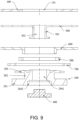
FIG. 1 illustrates a schematic structural view of a cylindrical battery provided by an embodiment of the disclosure.FIG. 2 illustrates a cross-sectional view of the assembled state of a battery pole end inFIG. 1 .FIG. 3 illustrates an exploded schematic view of the battery pole end inFIG. 1 . As shown inFIG. 1 to FIG. 3 , the embodiment provides a cylindrical battery, including acase 100, apole 200, a connectingpiece 300, and a sealingnail 400. Thecase 100 includes a cylindrical side wall and an end wall connected to the side wall, and a first throughhole 101 is disposed on the end wall. Thepole 200 includes a second throughhole 204 and passes through the first through hole 101 (refer toFIG. 3 ). The connectingpiece 300 is disposed in thecase 100, and the connectingpiece 300 includes aprotrusion 301. Theprotrusion 301 extends into the second throughhole 204, and theprotrusion 301 is fixedly connected to the inner wall of the second throughhole 204. The sealingnail 400 is hermetically fixed in the second throughhole 204. In the cylindrical battery, the second throughhole 204 is formed on thepole 200, and theprotrusion 301 is disposed on the connectingpiece 300, so that theprotrusion 301 can be fixedly connected to the inner wall of the second throughhole 204 and then seal the second throughhole 204 by the sealingnail 400, which ensures the sealing performance of thepole 200. - Optionally, the
protrusion 301 may be fixed to the inner wall of the second throughhole 204 by welding. For example, the outer peripheral surface of one end of theprotrusion 301 facing the sealingnail 400 and the inner wall of the second throughhole 204 are welded and fixed by butt welding. - Optionally, the
case 100 may be a steel case, and thepole 200 is a positive pole; or thecase 100 may be an aluminum case, and thepole 200 is a negative pole. - As shown in
FIG. 3 , thepole 200 includes a limitingportion 201 and a connectingportion 202. The limitingportion 201 is disposed outside thecase 100, the connectingportion 202 passes through the first throughhole 101 and is disposed at one end of thecase 100 with ariveting portion 203, and the second throughhole 204 penetrates the connectingportion 202. - As shown in
FIG. 3 andFIG. 2 , the cylindrical battery provided by the embodiment of the disclosure further includes a sealingelement 500. The sealingelement 500 is disposed between the limitingportion 201 of thepole 200 and the end wall of thecase 100. The cylindrical battery provided by the embodiment of the disclosure further includes an innerinsulating element 600, and at least part of the inner insulatingelement 600 is disposed between theriveting portion 203 and the end wall of thecase 100 to ensure the insulation setting between theriveting portion 203 and the end wall of thecase 100. The cylindrical battery further includes an outer insulatingelement 700, and at least part of the outer insulatingelement 700 is disposed between the limitingportion 201 and the end wall of thecase 100 to ensure the insulating setting between the limitingportion 201 and the end wall of thecase 100. Optionally, the cylindrical battery further includes the sealingelement 500, the sealingelement 500 is disposed around the connectingportion 202, and at least part of the sealingelement 500 is disposed between the limitingportion 201 and the end wall of thecase 100 to ensure that the sealingelement 500 has a sufficient amount of compression to ensure the sealing between thepole 200 and thecase 100. - Optionally, the material of the sealing
element 500 is fluorine rubber. - In
FIG. 2 , the inner insulatingelement 600 includes a first inner insulating portion and a second inner insulating portion vertically disposed. The first inner insulating portion is disposed between theriveting portion 203 of thepole 200 and the end wall of thecase 100, and the second inner insulating portion is disposed in the first throughhole 101. InFIG. 2 , the outer insulatingelement 700 is a flat plate, and the outer insulatingelement 700 is disposed between the limitingportion 201 of thepole 200 and the end wall of thecase 100. The sealingelement 500 is disposed between the inner annular surface of the outer insulatingelement 700 and the connectingportion 202 of thepole 200. In other embodiments, the inner insulatingelement 600 may also be a flat plate, the sealingelement 500 includes a first sealing portion and a second sealing portion, and the first sealing portion is disposed between the limitingportion 201 of thepole 200 and the end wall of thecase 100. The second sealing portion passes through the first throughhole 101 and abuts against the first throughhole 101. The outerinsulating element 700 includes a first outer insulating portion and a second outer insulating portion, the first outer insulating portion is disposed between the limitingportion 201 and the end wall, and the second outer insulating portion covers the outer peripheral surface of the limitingportion 201. In this design, the first outer insulating portion ensures the insulating setting of the limitingportion 201 and the end wall of thecase 100. By covering the outer peripheral surface of the limitingportion 201 through the second outer insulating portion, the outer peripheral surface of the limitingportion 201 is prevented from being in direct contact with the end wall of thecase 100, resulting from the assembly force compressing the outer insulatingelement 700. - Optionally, the area ratio of the inner insulating
element 600 to the end wall of thecase 100 is 0.7-1. Such a design enables the inner insulatingelement 600 to further ensure the insulating setting between the connecting piece of the cylindrical battery and the end wall of thecase 100. For example, the area ratio of the inner insulatingelement 600 to the end wall of thecase 100 is any value ranging from 0.7 to 1, such as 0.7, 0.8, 0.9, 1, and the like, as long as it can ensure that the inner insulatingelement 600 can ensure the insulating setting between the connecting piece and the end wall of thecase 100, which may not be specifically illustrated herein. Preferably, when the inner insulatingelement 600 includes the first inner insulating portion and the second inner insulating portion, at least part of the first inner insulating portion is disposed between theriveting portion 203 and the end wall, and at least part of the second inner insulating portion is disposed inside the first throughhole 101. In this design, the first inner insulating portion ensures the insulating setting between theriveting portion 203 and the end wall, and the second inner insulating portion ensures the insulating setting between the connectingportion 202 and the inner wall of the first throughhole 101 on the end wall. Furthermore, when the inner insulatingelement 600 includes the first inner insulating portion and the second inner insulating portion, the area ratio of the first inner insulating portion to the end wall of thecase 100 is 0.7-1. -
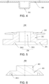
FIG. 4 illustrates a structural schematic view of the connectingpiece 300 provided by the embodiment of the disclosure.FIG. 5 illustrates a structural schematic view of thepole 200 provided by the embodiment of the disclosure.FIG. 6 illustrates a structural schematic view of the sealingnail 400 provided by the embodiment of the disclosure. As shown inFIG. 4 to FIG. 6 , the second throughhole 204 includes a straight throughportion 2041 and a firstconcave portion 2042 disposed in sequence along the direction from the inside of thecase 100 to the outside of thecase 100. Theprotrusion 301 of the connectingpiece 300 extends into the straight throughportion 2041, the sealingnail 400 includes acover portion 401, and thecover portion 401 is cooperated with the firstconcave portion 2042. - Optionally, the side wall of the first
concave portion 2042 and the bottom surface of the firstconcave portion 2042 are disposed at an obtuse angle, at a right angle, or at a rounded angle. Such a design facilitates the configuration of the sealingnail 400 in the firstconcave portion 2042. - As shown in
FIG. 4 andFIG. 2 , the surface of theprotrusion 301 facing the sealingnail 400 protrudes from the end wall of thecase 100. When theprotrusion 301 and the inner wall of the second throughhole 204 are fixed by welding, the design allows the welding part of theprotrusion 301 and the second throughhole 204 to face away from the battery core in thecase 100 to reduce the influence of welding heat on the battery core. Preferably, the surface of theprotrusion 301 facing the sealingnail 400 does not exceed the bottom surface of the firstconcave portion 2042. In this design, the length of the straight throughportion 2041 is greater than the length of theprotrusion 301, so that a certain space is reserved for the straight throughportion 2041 to cooperate with the sealingnail 400. - As shown in
FIG. 6 and FIG. 5 , thecover portion 401 of the sealingnail 400 and the firstconcave portion 2042 are fixedly connected by welding. For example, thecover portion 401 of the sealingnail 400 and the bottom surface of the firstconcave portion 2042 are welded by laser penetration welding, the laser device is located outside thecase 100, and the laser energy passes through thecover portion 401 of the sealingnail 400 to weld thecover portion 401 on the firstconcave portion 2042. In other embodiments, thecover portion 401 of the sealingnail 400 may also be welded and fixed to the side wall of the firstconcave portion 2042 by butt welding, that is, the outer peripheral surface of thecover portion 401 and the inner annular surface of the firstconcave portion 2042 are welded and fixed. The welding method can well control the laser energy and a virtual welding is prevented. - Preferably, after the sealing
nail 400 is welded and fixed to the firstconcave portion 2042, the surface of the sealingnail 400 facing away from the connectingpiece 300 does not exceed the end surface of thepole 200 outside thecase 100. Preferably, the end face of the sealingnail 400 facing away from the connectingpiece 300 is preferably less than the end face of thepole 200 outside thecase 100 for facilitating the connection between the end face of thepole 200 outside thecase 100 and the outer converging metal plate when the batteries are assembled. However, if the surface of the sealingnail 400 facing away from the connectingpiece 300 exceeds the end surface of thepole 200 outside thecase 100, interference may be generated, affecting the welding. - As shown in
FIG. 6 , the sealingnail 400 includes agroove 4011 for releasing welding stress. Thegroove 4011 is an annular groove formed on thecover portion 401. - Furthermore, on the bottom surface, the sealing
nail 400 further includes aplug portion 402, and theplug portion 402 is cooperated with the straight throughportion 2041. Such a design is adapted for a scenario in which the length of theprotrusion 301 of the connectingpiece 300 is less than the length of the straight throughportion 2041, and the assembly stability of the sealingnail 400 and thepole 200 is ensured by configuring theplug portion 402 on the sealingnail 400 to cooperate with the straight throughportion 2041. - For example, when the surface of the
protrusion 301 facing the sealingnail 400 is flush with the bottom surface of the firstconcave portion 2042, the shape of the sealingnail 400 may be a flat plate with only thecover portion 401 but without theplug portion 402. For example, the sealingnail 400 is thin cylindrical. When the surface of theprotrusion 301 facing the sealingnail 400 does not exceed and is not flush with the bottom surface of the firstconcave portion 2042, the shape of the sealingnail 400 may be a stepped shape with both thecover portion 401 and theplug portion 402. For example, the sealingnail 400 is stepped cylindrical. - The embodiment also provides an electronic device (not shown in the drawing), including the illustrated cylindrical battery. With the cylindrical battery, the safety is high.
-
FIG. 7 illustrates a schematic structural view of a cylindrical battery provided by another embodiment of the disclosure.FIG. 8 illustrates a cross-sectional view of a battery pole end in the assembled state inFIG. 7 .FIG. 9 illustrates an exploded schematic view of the battery pole end inFIG. 7 . As shown inFIG. 7 to FIG. 9 , the embodiment provides a cylindrical battery, including thecase 100, thepole 200, the connectingpiece 300, and the sealingnail 400. Thecase 100 includes a cylindrical side wall and an end wall connected to the side wall, and the first throughhole 101 is disposed on the end wall; thepole 200 includes the second throughhole 204, and thepole 200 passes through the first through hole 101 (refer toFIG. 9 ). The connectingpiece 300 is disposed in thecase 100, the connectingpiece 300 includes theprotrusion 301, theprotrusion 301 extends into the second throughhole 204, and theprotrusion 301 is fixedly connected to the inner wall of the second throughhole 204; the sealingnail 400 is hermetically fixed in the second throughhole 204. In the cylindrical battery, the second throughhole 204 is formed on thepole 200, and theprotrusion 301 is disposed on the connectingpiece 300, so that theprotrusion 301 can be fixedly connected to the inner wall of the second throughhole 204, and the sealing performance of thepole 200 is ensured by sealing the second throughhole 204 through the sealingnail 400. - Optionally, the
case 100 may be a steel case, and thepole 200 is a positive pole. - The main difference between the cylindrical battery provided in the embodiment and the cylindrical battery of the first embodiment is as follows.
- As shown in
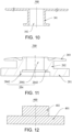
FIG. 10 andFIG. 9 , theprotrusion 301 includes a third throughhole 302, and the third throughhole 302 communicates with the second throughhole 204. The third throughhole 302 can be used as a liquid injection hole. Before assembling the sealingnail 400, the electrolyte is injected into thecase 100 through the second throughhole 204 and the third throughhole 302, and the assembly of the sealingnail 400 is performed after the electrolyte injection is completed. Compared with the liquid injection at the negative end of thecase 100 in the conventional technology, the battery assembly and liquid injection operations are more convenient in this method. - Optionally, the end of the
protrusion 301 facing the sealingnail 400 may be fixedly connected to the inner wall of the second throughhole 204 by welding or may be riveted to the inner wall of the second throughhole 204 by riveting. In the embodiment, theprotrusion 301 is preferably riveted and fixed to the inner wall of the second throughhole 204. -
FIG. 11 illustrates the structural schematic view of thepole 200 provided by an embodiment of the disclosure.FIG. 12 illustrates a schematic structural view of the sealingnail 400 provided by an embodiment of the disclosure. As shown inFIG. 11 to FIG. 12 , when theprotrusion 301 is riveted to the inner wall of the second throughhole 204, the second throughhole 204 further includes a secondconcave portion 2043, the secondconcave portion 2043 is disposed between the straight throughportion 2041 and the firstconcave portion 2042, and one end of theprotrusion 301 facing the sealingnail 400 is riveted and fixed to the secondconcave portion 2043. For example, the straight throughportion 2041, the secondconcave portion 2043 and the firstconcave portion 2042 are disposed in a form of a staircase, the diameter of the straight throughportion 2041 is less than the diameter of the secondconcave portion 2043, the diameter of the secondconcave portion 2043 is less than the diameter of the firstconcave portion 2042, and the end of theprotrusion 301 facing the sealingnail 400 is riveted to the stepped surface of the secondconcave portion 2043. - Optionally, the diameter of the connecting
portion 202 is D0, the diameter of the second throughhole 204 is D1, and 0.5D0<D1<0.8D0. For example, the diameter Di of the second throughhole 204 may be any value between 0.5D0<D1<0.8D0, such as 0.5D0, 0.6D0, 0.7D0, 0.8D0, and the like. - The embodiment also provides an electronic device (not shown in the drawing), including the illustrated cylindrical battery. With the cylindrical battery, the safety is high.
Claims (15)
- A cylindrical battery, comprising:a case (100), comprising a cylindrical side wall and an end wall connected to the side wall, wherein the end wall is provided with a first through hole (101);a pole (200), comprising a second through hole (204), wherein the pole (200) passes through the first through hole (101) and is fixed on the case (100);a connecting piece (300), disposed in the case (100), wherein the connecting piece (300) comprises a protrusion (301), the protrusion (301) extends into the second through hole (204), and the protrusion (301) is fixedly connected to an inner wall of the second through hole (204);a sealing nail (400), hermetically fixed in the second through hole (204).
- The cylindrical battery according to claim 1, wherein the second through hole (204) comprises a straight through portion (2041) and a first concave portion (2042) disposed in sequence along a direction from the inside of the case (100) to the outside of the case (100), and the sealing nail (400) comprises a cover portion (401) that is cooperated with the first concave portion (2042).
- The cylindrical battery according to claim 1 or 2, wherein a side wall of the first concave portion (2042) and a bottom surface of the first concave portion (2042) are disposed at an obtuse angle, at a right angle, or at a rounded angle.
- The cylindrical battery according to any one of claims 1-3, wherein a surface of the protrusion (301) facing the sealing nail (400) does not exceed a bottom surface of the first concave portion (2042).
- The cylindrical battery according to any one of claims 1-4, wherein a surface of the sealing nail (400) facing away from the connecting piece (300) does not exceed an end surface of the pole (200) outside the case (100).
- The cylindrical battery according to any one of claims 1-5, wherein the cover portion (401) is fixed to a bottom surface of the first concave portion (2042) by welding, or
the cover portion (401) is fixed to a side wall of the first concave portion (2042) by welding. - The cylindrical battery according to any one of claims 1-6, wherein a surface of the cover portion (401) facing away from the connecting piece (300) comprises a groove (4011).
- The cylindrical battery according to any one of claims 1-7, wherein a surface of the protrusion (301) facing the sealing nail (400) protrudes from the end wall of the case (100).
- The cylindrical battery according to any one of claims 1-8, wherein the protrusion (301) comprises a third through hole (302), and the third through hole (302) communicates with the second through hole (204).
- The cylindrical battery according to any one of claims 1-9, wherein the pole (200) comprises a limiting portion (201) and a connecting portion (202), the limiting portion (201) is located outside the case (100), the connecting portion (202) passes through the first through hole (101), and the second through hole (204) penetrates the connecting portion (202).
- The cylindrical battery according to any one of claims 1-10, wherein a diameter of the connecting portion (202) is D0, a diameter of the second through hole (204) is D1, and 0.5D0<D1<0.8D0.
- The cylindrical battery according to any one of claims 1-11, wherein the cylindrical battery further comprises a sealing element (500), the sealing element (500) is disposed around the connecting portion (202), and at least part of the sealing element (500) is disposed between the limiting portion (201) and the end wall of the case (100).
- The cylindrical battery according to any one of claims 1-12, wherein one end of the protrusion (301) facing the sealing nail (400) is fixed to the inner wall of the second through hole (204) by welding.
- The cylindrical battery according to any one of claims 1-13, wherein the second through hole (204) further comprises a second concave portion (2043), the second concave portion (2043) is disposed between the straight through portion (2041) and the first concave portion (2042), one end of the protrusion (301) facing the sealing nail (400) is riveted and fixed to the second concave portion (2043).
- An electronic device, comprising the cylindrical battery according to any one of claims 1-14.
Applications Claiming Priority (1)
| Application Number | Priority Date | Filing Date | Title |
|---|---|---|---|
| CN202210615465.2A CN114883757A (en) | 2022-05-31 | 2022-05-31 | Cylindrical battery and electronic equipment |
Publications (1)
| Publication Number | Publication Date |
|---|---|
| EP4287367A1 true EP4287367A1 (en) | 2023-12-06 |
Family
ID=82680412
Family Applications (1)
| Application Number | Title | Priority Date | Filing Date |
|---|---|---|---|
| EP22215809.9A Pending EP4287367A1 (en) | 2022-05-31 | 2022-12-22 | Cylindrical battery and electronic device |
Country Status (4)
| Country | Link |
|---|---|
| US (1) | US20230387521A1 (en) |
| EP (1) | EP4287367A1 (en) |
| JP (1) | JP2023177216A (en) |
| CN (1) | CN114883757A (en) |
Families Citing this family (1)
| Publication number | Priority date | Publication date | Assignee | Title |
|---|---|---|---|---|
| KR102619896B1 (en) * | 2022-10-04 | 2024-01-02 | 삼성에스디아이 주식회사 | Cylindrical secondary battery |
Citations (4)
| Publication number | Priority date | Publication date | Assignee | Title |
|---|---|---|---|---|
| US20180205044A1 (en) * | 2017-01-17 | 2018-07-19 | Fdk Corporation | Sealing body of tube-shaped battery and tube-shaped battery |
| CN215578674U (en) * | 2021-05-21 | 2022-01-18 | 湖北亿纬动力有限公司 | Assembling structure of positive pole and positive current collecting plate and battery |
| CN216085066U (en) * | 2021-10-29 | 2022-03-18 | 蜂巢能源科技(无锡)有限公司 | Cylinder lithium cell |
| EP3985699A1 (en) * | 2019-06-11 | 2022-04-20 | AVX New Energy (Chengdu) Co., Ltd | Electrochemical energy storage device |
Family Cites Families (7)
| Publication number | Priority date | Publication date | Assignee | Title |
|---|---|---|---|---|
| CN209447912U (en) * | 2019-03-13 | 2019-09-27 | 宁德时代新能源科技股份有限公司 | Secondary cell |
| CN209447920U (en) * | 2019-03-13 | 2019-09-27 | 宁德时代新能源科技股份有限公司 | Secondary cell |
| CN112886156B (en) * | 2021-03-15 | 2023-10-24 | 贵州中瑞丰泰新能源科技有限公司 | Battery structure capable of injecting liquid from end part of pole and battery liquid injection method |
| CN215070164U (en) * | 2021-06-30 | 2021-12-07 | 比亚迪股份有限公司 | A block subassembly and cylinder battery for cylinder battery |
| CN216389535U (en) * | 2021-11-08 | 2022-04-26 | 多氟多新能源科技有限公司 | Cylindrical lithium ion battery and battery module thereof |
| CN114447407A (en) * | 2022-01-28 | 2022-05-06 | 蓝京新能源(嘉兴)有限公司 | Cylindrical battery and manufacturing method thereof |
| CN114497904A (en) * | 2022-02-24 | 2022-05-13 | 中创新航科技股份有限公司 | Battery assembly method and battery |
-
2022
- 2022-05-31 CN CN202210615465.2A patent/CN114883757A/en active Pending
- 2022-12-21 US US18/086,583 patent/US20230387521A1/en active Pending
- 2022-12-21 JP JP2022204667A patent/JP2023177216A/en active Pending
- 2022-12-22 EP EP22215809.9A patent/EP4287367A1/en active Pending
Patent Citations (4)
| Publication number | Priority date | Publication date | Assignee | Title |
|---|---|---|---|---|
| US20180205044A1 (en) * | 2017-01-17 | 2018-07-19 | Fdk Corporation | Sealing body of tube-shaped battery and tube-shaped battery |
| EP3985699A1 (en) * | 2019-06-11 | 2022-04-20 | AVX New Energy (Chengdu) Co., Ltd | Electrochemical energy storage device |
| CN215578674U (en) * | 2021-05-21 | 2022-01-18 | 湖北亿纬动力有限公司 | Assembling structure of positive pole and positive current collecting plate and battery |
| CN216085066U (en) * | 2021-10-29 | 2022-03-18 | 蜂巢能源科技(无锡)有限公司 | Cylinder lithium cell |
Also Published As
| Publication number | Publication date |
|---|---|
| US20230387521A1 (en) | 2023-11-30 |
| CN114883757A (en) | 2022-08-09 |
| JP2023177216A (en) | 2023-12-13 |
Similar Documents
| Publication | Publication Date | Title |
|---|---|---|
| CN105830253B (en) | Rectangular secondary cell | |
| JP5525904B2 (en) | Secondary battery | |
| US20220158197A1 (en) | Electrode assembly and battery cell | |
| US10243190B2 (en) | Battery spacer, electric core protection assembly and power battery | |
| US20210119306A1 (en) | Secondary battery | |
| EP4287367A1 (en) | Cylindrical battery and electronic device | |
| EP4254613A1 (en) | Electrochemical apparatus and electronic device | |
| CN209087917U (en) | Secondary cell | |
| US11909066B1 (en) | Battery end cover assembly, energy storage apparatus and electric device | |
| CN217158403U (en) | Battery cell, battery and power consumption device | |
| EP4322314A1 (en) | Lithium battery and preparation method therefor | |
| CN214848969U (en) | Secondary cell's top cap subassembly and secondary cell | |
| CN207353302U (en) | Power battery cap assembly, power battery and battery modules | |
| CN219180738U (en) | Current collecting component and secondary battery | |
| CN209104289U (en) | Secondary cell | |
| WO2023025104A1 (en) | Battery cell, battery, and electric device | |
| CN104103850B (en) | Cylindrical lithium ion battery | |
| CN216928669U (en) | Lithium battery | |
| WO2023065186A1 (en) | Battery cell, battery, electrical device, and preparation method and apparatus for battery cell | |
| WO2020177599A1 (en) | Secondary battery | |
| CN218448363U (en) | Battery with a battery cell | |
| CN218586281U (en) | Secondary battery and electronic equipment | |
| CN220821851U (en) | Battery and car | |
| CN219086102U (en) | Screw-thread sealed high-multiplying-power cylindrical battery | |
| CN217134500U (en) | Battery cover plate assembly and button cell |
Legal Events
| Date | Code | Title | Description |
|---|---|---|---|
| PUAI | Public reference made under article 153(3) epc to a published international application that has entered the european phase |
Free format text: ORIGINAL CODE: 0009012 |
|
| STAA | Information on the status of an ep patent application or granted ep patent |
Free format text: STATUS: REQUEST FOR EXAMINATION WAS MADE |
|
| 17P | Request for examination filed |
Effective date: 20221222 |
|
| AK | Designated contracting states |
Kind code of ref document: A1 Designated state(s): AL AT BE BG CH CY CZ DE DK EE ES FI FR GB GR HR HU IE IS IT LI LT LU LV MC ME MK MT NL NO PL PT RO RS SE SI SK SM TR |
|
| RBV | Designated contracting states (corrected) |
Designated state(s): AL AT BE BG CH CY CZ DE DK EE ES FI FR GB GR HR HU IE IS IT LI LT LU LV MC ME MK MT NL NO PL PT RO RS SE SI SK SM TR |