EP4287363A1 - Battery pack power connection system and vehicle - Google Patents
Battery pack power connection system and vehicle Download PDFInfo
- Publication number
- EP4287363A1 EP4287363A1 EP22779021.9A EP22779021A EP4287363A1 EP 4287363 A1 EP4287363 A1 EP 4287363A1 EP 22779021 A EP22779021 A EP 22779021A EP 4287363 A1 EP4287363 A1 EP 4287363A1
- Authority
- EP
- European Patent Office
- Prior art keywords
- battery pack
- tray
- busbar
- power
- connector
- Prior art date
- Legal status (The legal status is an assumption and is not a legal conclusion. Google has not performed a legal analysis and makes no representation as to the accuracy of the status listed.)
- Withdrawn
Links
Images




Classifications
-
- H—ELECTRICITY
- H01—ELECTRIC ELEMENTS
- H01M—PROCESSES OR MEANS, e.g. BATTERIES, FOR THE DIRECT CONVERSION OF CHEMICAL ENERGY INTO ELECTRICAL ENERGY
- H01M10/00—Secondary cells; Manufacture thereof
- H01M10/42—Methods or arrangements for servicing or maintenance of secondary cells or secondary half-cells
- H01M10/425—Structural combination with electronic components, e.g. electronic circuits integrated to the outside of the casing
-
- H—ELECTRICITY
- H01—ELECTRIC ELEMENTS
- H01M—PROCESSES OR MEANS, e.g. BATTERIES, FOR THE DIRECT CONVERSION OF CHEMICAL ENERGY INTO ELECTRICAL ENERGY
- H01M50/00—Constructional details or processes of manufacture of the non-active parts of electrochemical cells other than fuel cells, e.g. hybrid cells
- H01M50/50—Current conducting connections for cells or batteries
- H01M50/502—Interconnectors for connecting terminals of adjacent batteries; Interconnectors for connecting cells outside a battery casing
- H01M50/505—Interconnectors for connecting terminals of adjacent batteries; Interconnectors for connecting cells outside a battery casing comprising a single busbar
-
- H—ELECTRICITY
- H01—ELECTRIC ELEMENTS
- H01M—PROCESSES OR MEANS, e.g. BATTERIES, FOR THE DIRECT CONVERSION OF CHEMICAL ENERGY INTO ELECTRICAL ENERGY
- H01M50/00—Constructional details or processes of manufacture of the non-active parts of electrochemical cells other than fuel cells, e.g. hybrid cells
- H01M50/20—Mountings; Secondary casings or frames; Racks, modules or packs; Suspension devices; Shock absorbers; Transport or carrying devices; Holders
- H01M50/298—Mountings; Secondary casings or frames; Racks, modules or packs; Suspension devices; Shock absorbers; Transport or carrying devices; Holders characterised by the wiring of battery packs
-
- H—ELECTRICITY
- H01—ELECTRIC ELEMENTS
- H01M—PROCESSES OR MEANS, e.g. BATTERIES, FOR THE DIRECT CONVERSION OF CHEMICAL ENERGY INTO ELECTRICAL ENERGY
- H01M10/00—Secondary cells; Manufacture thereof
- H01M10/42—Methods or arrangements for servicing or maintenance of secondary cells or secondary half-cells
-
- H—ELECTRICITY
- H01—ELECTRIC ELEMENTS
- H01M—PROCESSES OR MEANS, e.g. BATTERIES, FOR THE DIRECT CONVERSION OF CHEMICAL ENERGY INTO ELECTRICAL ENERGY
- H01M50/00—Constructional details or processes of manufacture of the non-active parts of electrochemical cells other than fuel cells, e.g. hybrid cells
- H01M50/20—Mountings; Secondary casings or frames; Racks, modules or packs; Suspension devices; Shock absorbers; Transport or carrying devices; Holders
- H01M50/204—Racks, modules or packs for multiple batteries or multiple cells
-
- H—ELECTRICITY
- H01—ELECTRIC ELEMENTS
- H01M—PROCESSES OR MEANS, e.g. BATTERIES, FOR THE DIRECT CONVERSION OF CHEMICAL ENERGY INTO ELECTRICAL ENERGY
- H01M50/00—Constructional details or processes of manufacture of the non-active parts of electrochemical cells other than fuel cells, e.g. hybrid cells
- H01M50/20—Mountings; Secondary casings or frames; Racks, modules or packs; Suspension devices; Shock absorbers; Transport or carrying devices; Holders
- H01M50/244—Secondary casings; Racks; Suspension devices; Carrying devices; Holders characterised by their mounting method
-
- H—ELECTRICITY
- H01—ELECTRIC ELEMENTS
- H01M—PROCESSES OR MEANS, e.g. BATTERIES, FOR THE DIRECT CONVERSION OF CHEMICAL ENERGY INTO ELECTRICAL ENERGY
- H01M50/00—Constructional details or processes of manufacture of the non-active parts of electrochemical cells other than fuel cells, e.g. hybrid cells
- H01M50/20—Mountings; Secondary casings or frames; Racks, modules or packs; Suspension devices; Shock absorbers; Transport or carrying devices; Holders
- H01M50/249—Mountings; Secondary casings or frames; Racks, modules or packs; Suspension devices; Shock absorbers; Transport or carrying devices; Holders specially adapted for aircraft or vehicles, e.g. cars or trains
-
- H—ELECTRICITY
- H01—ELECTRIC ELEMENTS
- H01M—PROCESSES OR MEANS, e.g. BATTERIES, FOR THE DIRECT CONVERSION OF CHEMICAL ENERGY INTO ELECTRICAL ENERGY
- H01M50/00—Constructional details or processes of manufacture of the non-active parts of electrochemical cells other than fuel cells, e.g. hybrid cells
- H01M50/50—Current conducting connections for cells or batteries
-
- H—ELECTRICITY
- H01—ELECTRIC ELEMENTS
- H01M—PROCESSES OR MEANS, e.g. BATTERIES, FOR THE DIRECT CONVERSION OF CHEMICAL ENERGY INTO ELECTRICAL ENERGY
- H01M50/00—Constructional details or processes of manufacture of the non-active parts of electrochemical cells other than fuel cells, e.g. hybrid cells
- H01M50/50—Current conducting connections for cells or batteries
- H01M50/502—Interconnectors for connecting terminals of adjacent batteries; Interconnectors for connecting cells outside a battery casing
- H01M50/503—Interconnectors for connecting terminals of adjacent batteries; Interconnectors for connecting cells outside a battery casing characterised by the shape of the interconnectors
-
- H—ELECTRICITY
- H01—ELECTRIC ELEMENTS
- H01M—PROCESSES OR MEANS, e.g. BATTERIES, FOR THE DIRECT CONVERSION OF CHEMICAL ENERGY INTO ELECTRICAL ENERGY
- H01M50/00—Constructional details or processes of manufacture of the non-active parts of electrochemical cells other than fuel cells, e.g. hybrid cells
- H01M50/50—Current conducting connections for cells or batteries
- H01M50/502—Interconnectors for connecting terminals of adjacent batteries; Interconnectors for connecting cells outside a battery casing
- H01M50/514—Methods for interconnecting adjacent batteries or cells
- H01M50/517—Methods for interconnecting adjacent batteries or cells by fixing means, e.g. screws, rivets or bolts
-
- H—ELECTRICITY
- H01—ELECTRIC ELEMENTS
- H01M—PROCESSES OR MEANS, e.g. BATTERIES, FOR THE DIRECT CONVERSION OF CHEMICAL ENERGY INTO ELECTRICAL ENERGY
- H01M50/00—Constructional details or processes of manufacture of the non-active parts of electrochemical cells other than fuel cells, e.g. hybrid cells
- H01M50/50—Current conducting connections for cells or batteries
- H01M50/502—Interconnectors for connecting terminals of adjacent batteries; Interconnectors for connecting cells outside a battery casing
- H01M50/519—Interconnectors for connecting terminals of adjacent batteries; Interconnectors for connecting cells outside a battery casing comprising printed circuit boards [PCB]
-
- H—ELECTRICITY
- H01—ELECTRIC ELEMENTS
- H01M—PROCESSES OR MEANS, e.g. BATTERIES, FOR THE DIRECT CONVERSION OF CHEMICAL ENERGY INTO ELECTRICAL ENERGY
- H01M2220/00—Batteries for particular applications
- H01M2220/20—Batteries in motive systems, e.g. vehicle, ship, plane
-
- Y—GENERAL TAGGING OF NEW TECHNOLOGICAL DEVELOPMENTS; GENERAL TAGGING OF CROSS-SECTIONAL TECHNOLOGIES SPANNING OVER SEVERAL SECTIONS OF THE IPC; TECHNICAL SUBJECTS COVERED BY FORMER USPC CROSS-REFERENCE ART COLLECTIONS [XRACs] AND DIGESTS
- Y02—TECHNOLOGIES OR APPLICATIONS FOR MITIGATION OR ADAPTATION AGAINST CLIMATE CHANGE
- Y02E—REDUCTION OF GREENHOUSE GAS [GHG] EMISSIONS, RELATED TO ENERGY GENERATION, TRANSMISSION OR DISTRIBUTION
- Y02E60/00—Enabling technologies; Technologies with a potential or indirect contribution to GHG emissions mitigation
- Y02E60/10—Energy storage using batteries
Definitions
- the present disclosure relates to the technical field of new energy vehicles, and particularly to a battery pack power connection system and a vehicle.
- Battery pack is the main power source of electric vehicles.
- An existing power connection form for battery packs is to electrically connect a connector and other components through a power connection busbar, such as a copper busbar or an aluminum busbar, to realize electrical transmission.
- a high-voltage distribution box is generally mounted at a head of the battery pack, a rear drive interface is close to a tail of the battery pack, and a power connection busbar spanning the entire battery pack is required for power connection. Therefore, how to design the power connection of the battery pack reasonably to make effective use of the space and improve the comfort of passengers is a problem to be solved.
- the technical problem to be solved by the present disclosure is to design the power connection of the battery pack reasonably to make effective use of the space. Accordingly, a battery pack power connection system and a vehicle are provided.
- an embodiment of the present disclosure provides a battery pack power connection system, including: a battery pack comprising a plurality of battery cores; a tray configured to support the battery pack; a distribution box configured to distribute input or output information of the battery pack; a first drive connector, one end of the first drive connector being connected with a first power system; and a power connector arranged in a cavity inner space of the tray and located between the plurality of battery cores, one end of the power connector being connected with the distribution box, and another end of the power connector being connected with another end of the first drive connector.
- the power connector is located at a welding hole of an extrusion cavity of the tray, a height of the power connector is less than or equal to a height of the welding hole, and a width of the power connector is less than or equal to a width of the welding hole.
- the power connector is a busbar.
- the busbar includes a conductor and a slider; and the slider is arranged between the conductor and the tray and is configured to fill a gap between the busbar and the tray.
- one side of the slider facing away from the conductor is provided with a groove, a first bottom width of the groove is less than an outer width of the groove, and the groove is configured to fix the busbar to the tray when the tray is inserted into the groove.
- the slider includes a locking structure, and the locking structure is configured to lock and fix the slider and the tray.
- a surface of the conductor is coated with an insulating layer.
- the busbar further includes a damping part, the damping part is arranged on the conductor, and the damping part is pearl cotton or foam.
- the busbar further includes a bracket, one end of the bracket is fixedly connected with the distribution box, another end of the bracket is connected with the busbar, and the distribution box is fixedly connected with the tray.
- the another end of the bracket is provided with a groove, and the busbar is fixedly connected with the bracket through the groove.
- the busbar includes a conductor, and the conductor is fixed to the tray by a glue, or the conductor is fixed to the tray by filling a flexible material.
- the battery pack power connection system further includes a second drive connector, one end of the second drive connector is connected with a second power system, and another end of the second drive connector is connected with the power connector.
- the power connector connected between the distribution box and the power system is arranged in the cavity inner space of the battery pack tray, i.e., the power connector extends through the inside of the tray, so as to make effective use of space in the battery pack and improve the comfort of passengers or drivers.
- an embodiment of the present disclosure provides a vehicle.
- the vehicle includes a first power system, a second power system, and the battery pack power connection system according to the foregoing aspect.
- a battery pack power connection system provided in an embodiment of the present disclosure includes a battery pack 3, a tray 5, a distribution box 1, a power connector 2, and a first drive connector 4.
- the battery pack 3 includes a plurality of battery cores 31.
- the tray 5 is configured to support the battery pack 3.
- the distribution box 1 is configured to distribute input or output information of the battery pack 3.
- the power connector 2 is arranged in a cavity inner space of the tray 5, and the power connector 2 is located between the plurality of battery cores 31.
- One end of the first drive connector is connected with a power system (e.g., a first power system 91).
- One end of the power connector 2 is connected with the distribution box 1, and another end of the power connector is connected with one end of the first drive connector 4.
- the power connector 2 connected between the distribution box 1 and the power system is arranged in the cavity inner space of the battery pack tray 5, i.e., the power connector 2 extends through the inside of the tray 5, so as to make effective use of space in the battery pack and improve the comfort of passengers or drivers.
- the first drive connector 4 can connect to and transmit power of a rear drive system (e.g., motor) of a vehicle.
- the first drive connector 4 may be a high-voltage connector connected to a rear drive motor of the vehicle.
- the connection between the battery pack and the power system may be achieved through the high-voltage connector connected to the rear drive motor of the vehicle; for the battery pack side, the connection between the battery pack and the power system may be achieved through the first drive connector 4.
- the first power system 91 may be a rear drive system such as a rear drive motor of the vehicle.
- the distribution box 1 in the embodiments of the present disclosure may include electrical connection components such as a relay, a fuse, and a copper busbar.
- the distribution box is not limited in the present disclosure.
- the tray 5 has a hollow design in the middle.
- a welding hole 51 may be a hole defined in the middle of the tray 5 by two profiles tailor-welded together.
- the power connector 2 is located in a welding hole 51 of an extrusion cavity of the tray 5.
- a height of the power connector 2 is less than or equal to a height of the welding hole 51, and a width of the power connector 2 is less than or equal to a width of the welding hole 51.
- two or more busbars may be inserted into the same welding hole 51.
- two or more power connectors 2 e.g., two or more busbars
- the size of the power connector is smaller than the size of the welding hole, so that the space in the battery pack can be further fully and reasonably utilized, to prevent the size of the power connector (regardless of width or height) from being too large to lead to a large size of the entire battery pack and affect the arrangements in the space of the battery pack.
- passenger vehicles have high requirements on the size of the battery pack in the height direction, and the design of the embodiments of the present disclosure can meet the requirements of passenger vehicles, reasonably utilize the space, and improve the driving experience of the driver and the comfort of passengers.
- the power connector can transmit power of the battery pack.
- Any device that can satisfy transmission conditions for example, a busbar, can be used as the power connector.
- the busbar may be a copper busbar or an aluminum busbar.
- the busbar may be connected with the distribution box 1 through a connection point 8.
- a first connection point 81 is configured to connect the distribution box to the busbar.
- the distribution box and the busbar may be connected at the connection point by a bolt.
- the busbar may also be connected with the first drive connector (e.g., a rear drive connector) 4 through a connection point 8.
- a second connection point 82 is configured to connect the rear drive connector 4 to the busbar.
- the rear drive connector and the busbar may be connected at the connection point by a bolt.
- the power connector 2 may include a conductor 21 and a slider 24.
- the slider 24 is arranged between the conductor 21 and the tray 5 and is configured to fill a gap between the busbar and the tray 5.
- the slider 24 may be fixed on the busbar, or may be inserted into the gap between the busbar and the tray 5 after the busbar is inserted into the tray 5, to ensure that the power connection busbar does not shake or displace in the space defined by tailor-welding in the extrusion cavity of the tray 5, thereby realizing positioning and limiting of the tray and the busbar.
- the material of the slider 24 may be polymer plastic or the like.
- one side of the slider 24 facing away from the conductor 21 is provided with a groove 241, and a bottom width of the groove 241 is less than an outer width of the groove 241.
- the groove 241 is designed to be narrow inside and wide outside, and is configured to fix the busbar to the tray 5 when the tray 5 is inserted into the groove 241. In other words, the slider 24 is slid into between the busbar and the tray 5 through guiding of the groove 241, so as to limit the busbar.
- the slider 24 includes a locking structure 243, and the locking structure 243 is configured to lock and fix the slider 24 and the tray 5.
- the locking structure 243 may be configured to resemble a door lock structure.
- the locking structure 243 may include a push rod, a spring, a cavity, and a locking tab.
- a mechanical sliding structure or spring mechanism may be designed in the slider 24, so that the slider 24 is mechanically locked and fixed to the tray 5 when the slider 24 reaches a deepest position in the groove 241.
- the slider 24 may also be clamped by a fixed bracket 25. As shown in FIG. 6 , to ensure the fixing stability.
- a surface of the conductor 21 is coated with an insulating layer 22.
- the insulating layer 22 can isolate an electric current between the conductors 21 or between the conductor 21 and an external electrical part, and provide insulation and separation functions. In this way, the electric current in the conductor 21 is transmitted along the conductor 21, thereby ensuring the transmission of electric energy, and realizing the external electrical part is isolated from electrically conductive parts of conductor 21, and preventing potential safety hazards such as electric shock.
- the material of the insulating layer 22 may be a heat shrinkable tube, polyvinyl chloride (PVC), polyimide (PI), epoxy resin, or the like.
- the insulating layer 22 may be formed by coating an insulating material on the surface of the conductor 21 through spraying or extrusion.
- the surface of the insulating layer 22 of the conductor 21 may further be coated with a layer of wear-resistant and voltage-resistant material.
- a layer of wear-resistant and voltage-resistant material For example, mica paper is further wound on the surface of the insulating material. This can strengthen the insulation effect, and achieve wear resistance and high temperature resistance.
- the busbar may further include a damping part 23.
- the damping part 23 is arranged on the conductor 21.
- the damping part 23 provides a damping effect and can absorb vibration energy to reducing the adverse effects such as abnormal sound or accelerated aging of the conductor 21 caused by vibration during traveling of the vehicle.
- the damping part 23 may be designed as two separate parts respectively above and below the conductor 21 or may be designed as an integral part.
- the damping part 23 may be adhered to the conductor 21 or wound on the conductor 21.
- the specific design and composition of the damping part and the manner in which damping part is fixed to the conductor 21 are not limited in the present disclosure, and any design that can absorb energy and provide a damping effect falls within the protection scope of the present disclosure.
- any material that can provide a damping effect may be used as the damping part 23.
- the damping part 23 may be pearl cotton or foam.
- the damping part 23 may be adhered to the insulating layer 22 on the surface of the conductor 21, i.e., the damping material may be adhered to the surface of the insulating layer 22 of the busbar or adhered to the surface of mica paper of reinforcing the insulation of the busbar.
- the damping part 23 is supported by the tray 5 in the longitudinal direction and provides a function of supporting the busbar on the tray 5.
- the transverse dimension of the damping part 23, i.e., the dimension of the damping part 23 between the two sides of the tray 5, may be designed to be slightly smaller than the conductor 21, to provide a function of fixing the busbar. In other words, the busbar and the tray may be limited by the damping part.
- the busbar further includes a bracket 25, one end of the bracket 25 is fixedly connected with the distribution box 1, another end of the bracket 25 is connected with the busbar, and the distribution box 1 is fixedly connected with the tray 5.
- a nut or steel heli coil may be buried in advance to reserve an interface for connection with the bracket 25.
- the bracket may be fixedly connected to the distribution box by a bolt.
- the bracket 25 may be fixed to the distribution box by a bolt 7.
- the distribution box 1 may be fixedly connected with the busbar through the bracket 25.
- one end of the bracket clamps the busbar, and the other end may be fixed in the distribution box through bolt connection.
- the distribution box 1 and the tray 5 may be connected by welding on their surfaces.
- the bracket 25 may be connected with the distribution box 1 in various forms.
- the bracket 25 may also be connected to the distribution box 1 by a bolt.
- the bracket 25 may be connected to the distribution box 1 by a glue.
- a recess and a limit hole may be reserved in the high-voltage distribution box 1.
- the bracket may be preliminarily fixed through the limit hole, and then the glue is poured into the recess to enhance the fixation.
- the amount of glue to be used depends on the vibration strength and adhesion strength.
- the connection mode using the glue is simple and easy to realize.
- the another end of the bracket 25 may be provided with a groove, and the busbar is fixedly connected with the bracket 25 through the groove.
- the bracket 25 may be fixed to the busbar by a fastener.
- the power connection busbar is clamped by a fastening apparatus whose groove width is slightly larger than a cross-sectional thickness of the power connection busbar, to ensure that the power connection busbar does not escape or shake.
- the material of the bracket 25 may be polypropylene (PP), polyamide 66 (PA66), etc.
- the busbar includes a conductor 21, and the conductor 21 and the tray 5 may be fixed by a glue.
- the conductor 21 and the tray 5 may also be fixed by filling a flexible material.
- the busbar may be connected with the distribution box 1 through a connection point 8.
- the first connection point 81 is configured to connect the distribution box to the busbar.
- the distribution box and the busbar may be connected at the connection point by a bolt.
- the busbar may also be connected with the first drive connector (e.g., a rear drive connector) 4 through the connection point 8.
- the second connection point 82 is configured to connect the rear drive connector 4 to the busbar.
- the rear drive connector and the busbar may be connected at the connection point by a bolt.
- the battery pack power connection system may further include a second drive connector 6.
- One end of the second drive connector 6 is connected with a second power system 92, and another end of the second drive connector 6 is connected with the power connector 2.
- the second power system 92 may be a front drive system such as a front drive motor.
- the second drive connector 6 may be a front drive connector connected to the front drive motor of the vehicle.
- the busbar in the embodiments of the present disclosure may be assembled by the following steps. First, the power connection busbar is inserted into the space defined by tailor-welding in the extrusion cavity of the tray 5, and the mounting position of the power connection busbar is determined and limited by the damping part 23 and the slider 24. The copper busbar is completely fixed on the tray 5 by the fixing bracket 25, and finally the power connection busbar is bent to a suitable position to realize the power connection between the busbar and the high-voltage distribution box 1 and the rear drive connector (such as a second power connector 2).
- an embodiment of the present disclosure provides a vehicle, including a first power system 91, a second power system 92, and the battery pack power connection system according to the above embodiment.
- first and second are used herein for purposes of description, and are not intended to indicate or imply relative importance or implicitly point out the number of the indicated technical feature. Therefore, the features defined by “first” and “second” may explicitly or implicitly include one or more features.
- the terms “mount”, “connect”, “couple”, “fix” and variants thereof should be interpreted in a broad sense, for example, may be a fixed connection, a detachable connection, or an integral connection; may be a mechanical connection or an electrical connection; or may be a direct connection, an indirectly connection via an intermediate medium, or communication between the interiors of two components or an interaction relationship between two elements.
- the specific meanings of the above terms in the present disclosure can be understood according to specific circumstances.
Landscapes
- Chemical & Material Sciences (AREA)
- Chemical Kinetics & Catalysis (AREA)
- Electrochemistry (AREA)
- General Chemical & Material Sciences (AREA)
- Engineering & Computer Science (AREA)
- Manufacturing & Machinery (AREA)
- Aviation & Aerospace Engineering (AREA)
- Microelectronics & Electronic Packaging (AREA)
- Battery Mounting, Suspending (AREA)
- Connection Of Batteries Or Terminals (AREA)
Abstract
Description
- This application claims priority to and benefits of
Chinese Patent Application No. 202110339878.8, filed on March 30, 2021 - The present disclosure relates to the technical field of new energy vehicles, and particularly to a battery pack power connection system and a vehicle.
- Battery pack is the main power source of electric vehicles. An existing power connection form for battery packs is to electrically connect a connector and other components through a power connection busbar, such as a copper busbar or an aluminum busbar, to realize electrical transmission. In a battery pack of a four-wheel drive vehicle, a high-voltage distribution box is generally mounted at a head of the battery pack, a rear drive interface is close to a tail of the battery pack, and a power connection busbar spanning the entire battery pack is required for power connection. Therefore, how to design the power connection of the battery pack reasonably to make effective use of the space and improve the comfort of passengers is a problem to be solved.
- The technical problem to be solved by the present disclosure is to design the power connection of the battery pack reasonably to make effective use of the space. Accordingly, a battery pack power connection system and a vehicle are provided.
- To solve the above technical problems, according to one aspect, an embodiment of the present disclosure provides a battery pack power connection system, including: a battery pack comprising a plurality of battery cores; a tray configured to support the battery pack; a distribution box configured to distribute input or output information of the battery pack; a first drive connector, one end of the first drive connector being connected with a first power system; and a power connector arranged in a cavity inner space of the tray and located between the plurality of battery cores, one end of the power connector being connected with the distribution box, and another end of the power connector being connected with another end of the first drive connector.
- According to an embodiment of the present disclosure, the power connector is located at a welding hole of an extrusion cavity of the tray, a height of the power connector is less than or equal to a height of the welding hole, and a width of the power connector is less than or equal to a width of the welding hole.
- According to an embodiment of the present disclosure, the power connector is a busbar.
- According to an embodiment of the present disclosure, the busbar includes a conductor and a slider; and the slider is arranged between the conductor and the tray and is configured to fill a gap between the busbar and the tray.
- According to an embodiment of the present disclosure, one side of the slider facing away from the conductor is provided with a groove, a first bottom width of the groove is less than an outer width of the groove, and the groove is configured to fix the busbar to the tray when the tray is inserted into the groove.
- According to an embodiment of the present disclosure, the slider includes a locking structure, and the locking structure is configured to lock and fix the slider and the tray.
- According to an embodiment of the present disclosure, a surface of the conductor is coated with an insulating layer.
- According to an embodiment of the present disclosure, the busbar further includes a damping part, the damping part is arranged on the conductor, and the damping part is pearl cotton or foam.
- According to an embodiment of the present disclosure, the busbar further includes a bracket, one end of the bracket is fixedly connected with the distribution box, another end of the bracket is connected with the busbar, and the distribution box is fixedly connected with the tray.
- According to an embodiment of the present disclosure, the another end of the bracket is provided with a groove, and the busbar is fixedly connected with the bracket through the groove.
- According to an embodiment of the present disclosure, the busbar includes a conductor, and the conductor is fixed to the tray by a glue, or the conductor is fixed to the tray by filling a flexible material.
- According to an embodiment of the present disclosure, the battery pack power connection system further includes a second drive connector, one end of the second drive connector is connected with a second power system, and another end of the second drive connector is connected with the power connector.
- According to an embodiment of the present disclosure, the power connector connected between the distribution box and the power system is arranged in the cavity inner space of the battery pack tray, i.e., the power connector extends through the inside of the tray, so as to make effective use of space in the battery pack and improve the comfort of passengers or drivers.
- According to another aspect, an embodiment of the present disclosure provides a vehicle. The vehicle includes a first power system, a second power system, and the battery pack power connection system according to the foregoing aspect.
-
-
FIG. 1 is a schematic structural diagram of a battery pack power connection system according to an embodiment of the present disclosure. -
FIG. 2 is a cross-sectional view of a battery pack power connection system according to an embodiment of the present disclosure. -
FIG. 3 is another cross-sectional view of a battery pack power connection system according to an embodiment of the present disclosure. -
FIG. 4 is a schematic structural diagram of a battery pack power connection busbar according to an embodiment of the present disclosure. -
FIG. 5 is a schematic three-dimensional diagram of a battery pack tray with an extrusion cavity according to an embodiment of the present disclosure. -
FIG. 6 is a schematic structural diagram of a battery pack power connection busbar fixed by a bracket and positioned by a slider according to an embodiment of the present disclosure. -
FIG. 7 is a detailed schematic structural enlarged view of a battery pack power connection busbar fixed by a bracket and positioned by a slider according to an embodiment of the present disclosure. - The reference numerals in the specification are as follow.
- 1. distribution box;
- 2. power connector; 21. conductor; 22. insulating layer; 23. damping part; 24. slider; 241. first groove; 243. locking structure; 25. bracket; 252. second groove;
- 3. battery pack; 31. battery core;
- 4. first drive connector;
- 5. tray; 51. welding hole;
- 6. second drive connector;
- 7. bolt;
- 8. connection point; 81. first connection point; 82. second connection point;
- 91. first power system; 92. second power system.
- To make the technical problems to be solved by the present disclosure, technical solutions, and beneficial effects more comprehensible, the following further describes the present disclosure in detail with reference to the accompanying drawings and embodiments. It should be understood that the specific embodiments described herein are merely used for explaining the present disclosure, and are not intended to limit the present disclosure.
- The battery pack power connection system of the present disclosure will be described in detail below with reference to the accompanying drawings. As shown in
FIG. 1 ,FIG. 2 , andFIG. 3 , a battery pack power connection system provided in an embodiment of the present disclosure includes a battery pack 3, atray 5, adistribution box 1, apower connector 2, and afirst drive connector 4. The battery pack 3 includes a plurality ofbattery cores 31. Thetray 5 is configured to support the battery pack 3. Thedistribution box 1 is configured to distribute input or output information of the battery pack 3. Thepower connector 2 is arranged in a cavity inner space of thetray 5, and thepower connector 2 is located between the plurality ofbattery cores 31. One end of the first drive connector is connected with a power system (e.g., a first power system 91). One end of thepower connector 2 is connected with thedistribution box 1, and another end of the power connector is connected with one end of thefirst drive connector 4. - According to an embodiment of the present disclosure, the
power connector 2 connected between thedistribution box 1 and the power system is arranged in the cavity inner space of thebattery pack tray 5, i.e., thepower connector 2 extends through the inside of thetray 5, so as to make effective use of space in the battery pack and improve the comfort of passengers or drivers. - In an embodiment of the present disclosure, one end of the
first drive connector 4 is connected with the battery pack 3, and another end of the first drive connector is connected with thefirst power system 91. Thefirst drive connector 4 can connect to and transmit power of a rear drive system (e.g., motor) of a vehicle. Thefirst drive connector 4 may be a high-voltage connector connected to a rear drive motor of the vehicle. Specifically, for the power system side, the connection between the battery pack and the power system may be achieved through the high-voltage connector connected to the rear drive motor of the vehicle; for the battery pack side, the connection between the battery pack and the power system may be achieved through thefirst drive connector 4. Thefirst power system 91 may be a rear drive system such as a rear drive motor of the vehicle. - The
distribution box 1 in the embodiments of the present disclosure may include electrical connection components such as a relay, a fuse, and a copper busbar. The distribution box is not limited in the present disclosure. - As shown in
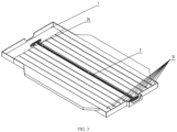
FIG. 5 , in an embodiment of the present disclosure, thetray 5 has a hollow design in the middle. Awelding hole 51 may be a hole defined in the middle of thetray 5 by two profiles tailor-welded together. - In an embodiment of the present disclosure, the
power connector 2 is located in awelding hole 51 of an extrusion cavity of thetray 5. A height of thepower connector 2 is less than or equal to a height of thewelding hole 51, and a width of thepower connector 2 is less than or equal to a width of thewelding hole 51. - It should be understood that when the size of space of the
welding hole 51 is sufficient for two ormore power connectors 2 to pass through, for example, when the size of thewelding hole 51 is larger than or equal to the size of two or more busbars, two or more busbars may be inserted into thesame welding hole 51. In other words, two or more power connectors 2 (e.g., two or more busbars) may be stacked in a longitudinal direction of the vehicle according to the actual size to improve space utilization. - In the embodiment of the disclosure, the size of the power connector is smaller than the size of the welding hole, so that the space in the battery pack can be further fully and reasonably utilized, to prevent the size of the power connector (regardless of width or height) from being too large to lead to a large size of the entire battery pack and affect the arrangements in the space of the battery pack. In particular, passenger vehicles have high requirements on the size of the battery pack in the height direction, and the design of the embodiments of the present disclosure can meet the requirements of passenger vehicles, reasonably utilize the space, and improve the driving experience of the driver and the comfort of passengers.
- In the embodiments of the present disclosure, the power connector can transmit power of the battery pack. Any device that can satisfy transmission conditions, for example, a busbar, can be used as the power connector. The busbar may be a copper busbar or an aluminum busbar.
- The busbar may be connected with the
distribution box 1 through aconnection point 8. For example, as shown inFIG. 6 , afirst connection point 81 is configured to connect the distribution box to the busbar. Specifically, the distribution box and the busbar may be connected at the connection point by a bolt. - In addition, the busbar may also be connected with the first drive connector (e.g., a rear drive connector) 4 through a
connection point 8. For example, as shown inFIG. 6 , asecond connection point 82 is configured to connect therear drive connector 4 to the busbar. Specifically, the rear drive connector and the busbar may be connected at the connection point by a bolt. - As shown in
FIG. 3 ,FIG. 4 ,FIG. 6 andFIG. 7 , in an embodiment of the present disclosure, the power connector 2 (e.g., busbar) may include aconductor 21 and aslider 24. Theslider 24 is arranged between theconductor 21 and thetray 5 and is configured to fill a gap between the busbar and thetray 5. Theslider 24 may be fixed on the busbar, or may be inserted into the gap between the busbar and thetray 5 after the busbar is inserted into thetray 5, to ensure that the power connection busbar does not shake or displace in the space defined by tailor-welding in the extrusion cavity of thetray 5, thereby realizing positioning and limiting of the tray and the busbar. The material of theslider 24 may be polymer plastic or the like. - In an embodiment of the present disclosure, one side of the
slider 24 facing away from theconductor 21 is provided with agroove 241, and a bottom width of thegroove 241 is less than an outer width of thegroove 241. Thegroove 241 is designed to be narrow inside and wide outside, and is configured to fix the busbar to thetray 5 when thetray 5 is inserted into thegroove 241. In other words, theslider 24 is slid into between the busbar and thetray 5 through guiding of thegroove 241, so as to limit the busbar. - In an embodiment of the present disclosure, the
slider 24 includes a lockingstructure 243, and the lockingstructure 243 is configured to lock and fix theslider 24 and thetray 5. For example, the lockingstructure 243 may be configured to resemble a door lock structure. In an embodiment, the lockingstructure 243 may include a push rod, a spring, a cavity, and a locking tab. In other words, a mechanical sliding structure or spring mechanism may be designed in theslider 24, so that theslider 24 is mechanically locked and fixed to thetray 5 when theslider 24 reaches a deepest position in thegroove 241. In addition, theslider 24 may also be clamped by a fixedbracket 25. As shown inFIG. 6 , to ensure the fixing stability. - In an embodiment of the present disclosure, a surface of the
conductor 21 is coated with an insulatinglayer 22. The insulatinglayer 22 can isolate an electric current between theconductors 21 or between theconductor 21 and an external electrical part, and provide insulation and separation functions. In this way, the electric current in theconductor 21 is transmitted along theconductor 21, thereby ensuring the transmission of electric energy, and realizing the external electrical part is isolated from electrically conductive parts ofconductor 21, and preventing potential safety hazards such as electric shock. The material of the insulatinglayer 22 may be a heat shrinkable tube, polyvinyl chloride (PVC), polyimide (PI), epoxy resin, or the like. The insulatinglayer 22 may be formed by coating an insulating material on the surface of theconductor 21 through spraying or extrusion. - In addition, the surface of the insulating
layer 22 of theconductor 21 may further be coated with a layer of wear-resistant and voltage-resistant material. For example, mica paper is further wound on the surface of the insulating material. This can strengthen the insulation effect, and achieve wear resistance and high temperature resistance. As shown inFIG. 4 andFIG. 6 , in an embodiment of the present disclosure, the busbar may further include a dampingpart 23. The dampingpart 23 is arranged on theconductor 21. The dampingpart 23 provides a damping effect and can absorb vibration energy to reducing the adverse effects such as abnormal sound or accelerated aging of theconductor 21 caused by vibration during traveling of the vehicle. In an embodiment of the present disclosure, the dampingpart 23 may be designed as two separate parts respectively above and below theconductor 21 or may be designed as an integral part. The dampingpart 23 may be adhered to theconductor 21 or wound on theconductor 21. The specific design and composition of the damping part and the manner in which damping part is fixed to theconductor 21 are not limited in the present disclosure, and any design that can absorb energy and provide a damping effect falls within the protection scope of the present disclosure. - In the embodiments of the present disclosure, any material that can provide a damping effect may be used as the damping
part 23. For example, the dampingpart 23 may be pearl cotton or foam. - The damping
part 23 may be adhered to the insulatinglayer 22 on the surface of theconductor 21, i.e., the damping material may be adhered to the surface of the insulatinglayer 22 of the busbar or adhered to the surface of mica paper of reinforcing the insulation of the busbar. - The damping
part 23 is supported by thetray 5 in the longitudinal direction and provides a function of supporting the busbar on thetray 5. In addition, the transverse dimension of the dampingpart 23, i.e., the dimension of the dampingpart 23 between the two sides of thetray 5, may be designed to be slightly smaller than theconductor 21, to provide a function of fixing the busbar. In other words, the busbar and the tray may be limited by the damping part. - As shown in
FIG. 2 ,FIG. 3 ,FIG. 6 andFIG. 7 , in an embodiment of the present disclosure, the busbar further includes abracket 25, one end of thebracket 25 is fixedly connected with thedistribution box 1, another end of thebracket 25 is connected with the busbar, and thedistribution box 1 is fixedly connected with thetray 5. During design of thedistribution box 1, a nut or steel heli coil may be buried in advance to reserve an interface for connection with thebracket 25. The bracket may be fixedly connected to the distribution box by a bolt. For example, thebracket 25 may be fixed to the distribution box by a bolt 7. Thedistribution box 1 may be fixedly connected with the busbar through thebracket 25. For example, one end of the bracket clamps the busbar, and the other end may be fixed in the distribution box through bolt connection. Thedistribution box 1 and thetray 5 may be connected by welding on their surfaces. - The
bracket 25 may be connected with thedistribution box 1 in various forms. For example, thebracket 25 may also be connected to thedistribution box 1 by a bolt. For another example, thebracket 25 may be connected to thedistribution box 1 by a glue. For example, a recess and a limit hole may be reserved in the high-voltage distribution box 1. The bracket may be preliminarily fixed through the limit hole, and then the glue is poured into the recess to enhance the fixation. The amount of glue to be used depends on the vibration strength and adhesion strength. The connection mode using the glue is simple and easy to realize. - In an embodiment of the present disclosure, the another end of the
bracket 25 may be provided with a groove, and the busbar is fixedly connected with thebracket 25 through the groove. For example, thebracket 25 may be fixed to the busbar by a fastener. The power connection busbar is clamped by a fastening apparatus whose groove width is slightly larger than a cross-sectional thickness of the power connection busbar, to ensure that the power connection busbar does not escape or shake. The material of thebracket 25 may be polypropylene (PP), polyamide 66 (PA66), etc. - In an embodiment of the present disclosure, the busbar includes a
conductor 21, and theconductor 21 and thetray 5 may be fixed by a glue. Theconductor 21 and thetray 5 may also be fixed by filling a flexible material. - The busbar may be connected with the
distribution box 1 through aconnection point 8. For example, as shown inFIG. 6 , thefirst connection point 81 is configured to connect the distribution box to the busbar. Specifically, the distribution box and the busbar may be connected at the connection point by a bolt. - In addition, the busbar may also be connected with the first drive connector (e.g., a rear drive connector) 4 through the
connection point 8. For example, as shown inFIG. 6 , thesecond connection point 82 is configured to connect therear drive connector 4 to the busbar. Specifically, the rear drive connector and the busbar may be connected at the connection point by a bolt. - The battery pack power connection system may further include a second drive connector 6. One end of the second drive connector 6 is connected with a
second power system 92, and another end of the second drive connector 6 is connected with thepower connector 2. Thesecond power system 92 may be a front drive system such as a front drive motor. The second drive connector 6 may be a front drive connector connected to the front drive motor of the vehicle. - The busbar in the embodiments of the present disclosure may be assembled by the following steps. First, the power connection busbar is inserted into the space defined by tailor-welding in the extrusion cavity of the
tray 5, and the mounting position of the power connection busbar is determined and limited by the dampingpart 23 and theslider 24. The copper busbar is completely fixed on thetray 5 by the fixingbracket 25, and finally the power connection busbar is bent to a suitable position to realize the power connection between the busbar and the high-voltage distribution box 1 and the rear drive connector (such as a second power connector 2). - In addition, an embodiment of the present disclosure provides a vehicle, including a
first power system 91, asecond power system 92, and the battery pack power connection system according to the above embodiment. - The terms "first" and "second" are used herein for purposes of description, and are not intended to indicate or imply relative importance or implicitly point out the number of the indicated technical feature. Therefore, the features defined by "first" and "second" may explicitly or implicitly include one or more features.
- In the present disclosure, unless otherwise clearly specified and defined, the terms "mount", "connect", "couple", "fix" and variants thereof should be interpreted in a broad sense, for example, may be a fixed connection, a detachable connection, or an integral connection; may be a mechanical connection or an electrical connection; or may be a direct connection, an indirectly connection via an intermediate medium, or communication between the interiors of two components or an interaction relationship between two elements. For those of ordinary skill in the art, the specific meanings of the above terms in the present disclosure can be understood according to specific circumstances.
- In the description of the specification, the description with reference to the terms "an embodiment", "one embodiment", "some embodiments", "example", "specific example", or "some example" and so on means that specific features, structures, materials or characteristics described in connection with the embodiment or example are embraced in at least one embodiment or example of the present disclosure. In the specification, the illustrative expression of the above terms is not necessarily referring to the same embodiment or example. Moreover, the described specific features, structures, materials or characteristics may be combined in any suitable manners in one or more embodiments. In addition, where there are no contradictions, the various embodiments or examples described in this specification and features of various embodiments or examples can be combined by those skilled in the art.
- The foregoing descriptions are merely optional embodiments of the present disclosure, but are not intended to limit the present disclosure. Any modification, equivalent replacement, or improvement made within the spirit and principle of the present disclosure shall fall within the protection scope of the present disclosure.
Claims (13)
- A battery pack power connection system, comprising:a battery pack (3) comprising a plurality of battery cores (31);a tray (5) configured to support the battery pack;a distribution box (1) configured to distribute input or output information of the battery pack (3);a first drive connector (4), one end of the first drive connector (4) being connected with a first power system (91); anda power connector (2) arranged in a cavity inner space of the tray (5) and located between the plurality of battery cores (31), one end of the power connector (2) being connected with the distribution box (1), and another end of the power connector (2) being connected with another end of the first drive connector (4).
- The battery pack power connection system according to claim 1, wherein the power connector (2) is located at a welding hole of an extrusion cavity of the tray (5), a height of the power connector (2) is less than or equal to a height of the welding hole, and a width of the power connector (2) is less than or equal to a width of the welding hole.
- The battery pack power connection system according to claim 1 or 2, wherein the power connector (2) is a busbar.
- The battery pack power connection system according to claim 3, wherein the busbar comprises a conductor (21) and a slider (24); and
the slider (24) is arranged between the conductor (21) and the tray (5) and is configured to fill a gap between the busbar and the tray (5). - The battery pack power connection system according to claim 4, wherein one side of the slider (24) facing away from the conductor (21) is provided with a first groove (241), a first bottom width of the first groove (241) is less than an outer width of the first groove (241), and the first groove (241) is configured to fix the busbar to the tray (5) when the tray (5) is inserted into the first groove (241).
- The battery pack power connection system according to claim 4, wherein the slider (24) comprises a locking structure (243), and the locking structure (243) is configured to lock and fix the slider (24) and the tray (5).
- The battery pack power connection system according to any one of claims 4-6, wherein a surface of the conductor (21) is coated with an insulating layer (22).
- The battery pack power connection system according to any one of claims 4-6, wherein the busbar further comprises a damping part (23), the damping part (23) is arranged on the conductor (21), and the damping part (23) is pearl cotton or foam.
- The battery pack power connection system according to any one of claims 4-6, wherein the busbar further comprises a bracket (25), one end of the bracket (25) is fixedly connected with the distribution box (1), another end of the bracket is connected with the busbar, and the distribution box (1) is fixedly connected with the tray (5).
- The battery pack power connection system according to claim 9, wherein the another end of the bracket (25) is provided with a second groove (252), and the busbar is fixedly connected with the bracket (25) through the second groove (252).
- The battery pack power connection system according to claim 3, wherein the busbar comprises a conductor (21), and the conductor (21) is fixed to the tray (5) by a glue, or the conductor (21) is fixed to the tray (5) by filling a flexible material.
- The battery pack power connection system according to any one of claims 1-11, wherein the battery pack power connection system further comprises a second drive connector (6), one end of the second drive connector (6) is connected with a second power system (92), and another end of the second drive connector (6) is connected with the power connector (2).
- A vehicle, characterised in that the vehicle comprises a first power system (91), a second power system (92), and the battery pack power connection system according to any one of claims 1-12.
Applications Claiming Priority (2)
| Application Number | Priority Date | Filing Date | Title |
|---|---|---|---|
| CN202110339878.8A CN115149171A (en) | 2021-03-30 | 2021-03-30 | Battery pack power connection system and vehicle |
| PCT/CN2022/084077 WO2022206839A1 (en) | 2021-03-30 | 2022-03-30 | Battery pack power connection system and vehicle |
Publications (2)
| Publication Number | Publication Date |
|---|---|
| EP4287363A1 true EP4287363A1 (en) | 2023-12-06 |
| EP4287363A4 EP4287363A4 (en) | 2024-10-09 |
Family
ID=83404448
Family Applications (1)
| Application Number | Title | Priority Date | Filing Date |
|---|---|---|---|
| EP22779021.9A Withdrawn EP4287363A4 (en) | 2021-03-30 | 2022-03-30 | BATTERY PACK AND VEHICLE ELECTRICAL CONNECTION SYSTEM |
Country Status (6)
| Country | Link |
|---|---|
| US (1) | US20230402720A1 (en) |
| EP (1) | EP4287363A4 (en) |
| JP (1) | JP2024507686A (en) |
| KR (1) | KR20230129033A (en) |
| CN (1) | CN115149171A (en) |
| WO (1) | WO2022206839A1 (en) |
Families Citing this family (2)
| Publication number | Priority date | Publication date | Assignee | Title |
|---|---|---|---|---|
| KR20250025123A (en) * | 2023-08-14 | 2025-02-21 | 주식회사 엘지에너지솔루션 | Busbar assembly and battery pack including the same |
| CN222355340U (en) * | 2023-12-01 | 2025-01-14 | 比亚迪股份有限公司 | Power extraction structure for battery pack, battery pack and vehicle |
Family Cites Families (18)
| Publication number | Priority date | Publication date | Assignee | Title |
|---|---|---|---|---|
| CN102084517A (en) * | 2008-05-15 | 2011-06-01 | 江森自控帅福得先进能源动力系统有限责任公司 | Battery system |
| US9472791B2 (en) * | 2011-08-11 | 2016-10-18 | Johnson Controls Technology Company | Battery system, housing and vehicle including battery system |
| WO2013084942A1 (en) * | 2011-12-09 | 2013-06-13 | 本田技研工業株式会社 | Battery pack for electric car |
| JP2013218927A (en) * | 2012-04-10 | 2013-10-24 | Sanyo Electric Co Ltd | Battery pack |
| JP6020959B2 (en) * | 2012-07-13 | 2016-11-02 | 三菱自動車工業株式会社 | Vehicle battery pack |
| JP2015220025A (en) * | 2014-05-15 | 2015-12-07 | 三菱自動車工業株式会社 | Bus bar for battery connection |
| CN105216645B (en) * | 2015-10-19 | 2018-03-13 | 北京新能源汽车股份有限公司 | Battery pack quick-change control system and method for electric automobile |
| CN107546351B (en) * | 2016-04-11 | 2020-10-23 | 比亚迪股份有限公司 | first sub-base |
| US10632856B2 (en) * | 2017-01-19 | 2020-04-28 | Ford Global Technologies, Llc | Connector-integrated endplate for battery electric vehicles |
| CN207876455U (en) * | 2018-02-09 | 2018-09-18 | 苏州宝优际科技股份有限公司 | Battery pack tray |
| CN108767178A (en) * | 2018-03-28 | 2018-11-06 | 北京普莱德新能源电池科技有限公司 | Printing board PCB pallet and battery modules |
| JP7205989B2 (en) * | 2018-12-26 | 2023-01-17 | カワサキモータース株式会社 | BATTERY PACK AND MOBILE BODY INCLUDING IT |
| CN209266454U (en) * | 2019-01-09 | 2019-08-16 | 东风小康汽车有限公司重庆分公司 | A kind of battery pack assembly |
| JP2021019464A (en) * | 2019-07-22 | 2021-02-15 | 住友電気工業株式会社 | Rechargeable battery and electrical power system |
| CN111645618B (en) * | 2020-05-15 | 2022-07-15 | 东风汽车集团有限公司 | A split-type high-voltage distribution box for pure electric vehicles |
| CN212113807U (en) * | 2020-05-21 | 2020-12-08 | 徐州创之社通用技术产业研究院有限公司 | A new energy vehicle battery bracket |
| CN113889708B (en) * | 2020-06-19 | 2022-11-11 | 比亚迪股份有限公司 | Vehicle and battery pack thereof |
| CN112271368A (en) * | 2020-10-12 | 2021-01-26 | 东风时代(武汉)电池系统有限公司 | High energy density power battery package integrated configuration and new energy automobile |
-
2021
- 2021-03-30 CN CN202110339878.8A patent/CN115149171A/en active Pending
-
2022
- 2022-03-30 KR KR1020237026585A patent/KR20230129033A/en not_active Ceased
- 2022-03-30 EP EP22779021.9A patent/EP4287363A4/en not_active Withdrawn
- 2022-03-30 JP JP2023545767A patent/JP2024507686A/en active Pending
- 2022-03-30 WO PCT/CN2022/084077 patent/WO2022206839A1/en not_active Ceased
-
2023
- 2023-08-28 US US18/457,100 patent/US20230402720A1/en active Pending
Also Published As
| Publication number | Publication date |
|---|---|
| CN115149171A (en) | 2022-10-04 |
| JP2024507686A (en) | 2024-02-21 |
| KR20230129033A (en) | 2023-09-05 |
| EP4287363A4 (en) | 2024-10-09 |
| US20230402720A1 (en) | 2023-12-14 |
| WO2022206839A1 (en) | 2022-10-06 |
Similar Documents
| Publication | Publication Date | Title |
|---|---|---|
| US20230402720A1 (en) | Battery pack power connection system and vehicle | |
| US10232697B2 (en) | Battery mounting structure for vehicle | |
| KR101990394B1 (en) | Power relay assembly | |
| KR101490648B1 (en) | Vehicle component mounting arrangement | |
| EP3761390B1 (en) | Connecting assembly and battery pack | |
| EP2665147B1 (en) | High voltage device system of a railcar, and railcar | |
| CN104682722A (en) | Power switching device and assembling method thereof | |
| GB2524438B (en) | Electric power connector for aircraft drive wheel drive system | |
| CN108698547A (en) | harness | |
| EP4321389A1 (en) | Automotive wire harness with a flexible connection section | |
| US20160172943A1 (en) | Electric motor for a motor vehicle with emc measure | |
| JP7176939B2 (en) | Power supply unit | |
| US20260031488A1 (en) | Battery pack and electrical apparatus | |
| KR102411445B1 (en) | High power relay assembly | |
| EP2738775B1 (en) | High-voltage conduction path and wiring harness | |
| CN118336449A (en) | Wire deconcentrator for automobile production wiring | |
| US12403850B2 (en) | Wire harness mounting structure | |
| CN215826463U (en) | Vehicle battery system and vehicle | |
| JP6520190B2 (en) | Wiring structure of vehicle harness | |
| CN217835372U (en) | Direct-current high-voltage distribution box for automobile | |
| CN209929921U (en) | Epoxy resin vulcanization insulation bus of high-voltage distribution box of new energy automobile | |
| CN223785614U (en) | High-voltage distribution boxes and vehicles | |
| CN218586192U (en) | Battery pack | |
| CN224130892U (en) | Electrical structure, chassis and vehicle | |
| CN214477797U (en) | Power battery system structure |
Legal Events
| Date | Code | Title | Description |
|---|---|---|---|
| STAA | Information on the status of an ep patent application or granted ep patent |
Free format text: STATUS: THE INTERNATIONAL PUBLICATION HAS BEEN MADE |
|
| PUAI | Public reference made under article 153(3) epc to a published international application that has entered the european phase |
Free format text: ORIGINAL CODE: 0009012 |
|
| STAA | Information on the status of an ep patent application or granted ep patent |
Free format text: STATUS: REQUEST FOR EXAMINATION WAS MADE |
|
| 17P | Request for examination filed |
Effective date: 20230831 |
|
| AK | Designated contracting states |
Kind code of ref document: A1 Designated state(s): AL AT BE BG CH CY CZ DE DK EE ES FI FR GB GR HR HU IE IS IT LI LT LU LV MC MK MT NL NO PL PT RO RS SE SI SK SM TR |
|
| DAV | Request for validation of the european patent (deleted) | ||
| DAX | Request for extension of the european patent (deleted) | ||
| A4 | Supplementary search report drawn up and despatched |
Effective date: 20240906 |
|
| RIC1 | Information provided on ipc code assigned before grant |
Ipc: H01M 50/519 20210101ALI20240902BHEP Ipc: H01M 50/505 20210101ALI20240902BHEP Ipc: H01M 50/503 20210101ALI20240902BHEP Ipc: H01M 50/249 20210101ALI20240902BHEP Ipc: H01M 50/204 20210101ALI20240902BHEP Ipc: H01M 10/42 20060101ALI20240902BHEP Ipc: H01M 50/10 20210101AFI20240902BHEP |
|
| STAA | Information on the status of an ep patent application or granted ep patent |
Free format text: STATUS: THE APPLICATION IS DEEMED TO BE WITHDRAWN |
|
| 18D | Application deemed to be withdrawn |
Effective date: 20250325 |