EP4287232A1 - Insulated earthing switch for an air insulated or mixed switchgear - Google Patents
Insulated earthing switch for an air insulated or mixed switchgear Download PDFInfo
- Publication number
- EP4287232A1 EP4287232A1 EP22177030.8A EP22177030A EP4287232A1 EP 4287232 A1 EP4287232 A1 EP 4287232A1 EP 22177030 A EP22177030 A EP 22177030A EP 4287232 A1 EP4287232 A1 EP 4287232A1
- Authority
- EP
- European Patent Office
- Prior art keywords
- switchgear
- housing
- switch
- earthing switch
- fasteners
- Prior art date
- Legal status (The legal status is an assumption and is not a legal conclusion. Google has not performed a legal analysis and makes no representation as to the accuracy of the status listed.)
- Granted
Links
Images



Classifications
-
- H—ELECTRICITY
- H01—ELECTRIC ELEMENTS
- H01H—ELECTRIC SWITCHES; RELAYS; SELECTORS; EMERGENCY PROTECTIVE DEVICES
- H01H33/00—High-tension or heavy-current switches with arc-extinguishing or arc-preventing means
- H01H33/02—Details
- H01H33/53—Cases; Reservoirs, tanks, piping or valves, for arc-extinguishing fluid; Accessories therefor, e.g. safety arrangements, pressure relief devices
- H01H33/56—Gas reservoirs
-
- H—ELECTRICITY
- H02—GENERATION; CONVERSION OR DISTRIBUTION OF ELECTRIC POWER
- H02B—BOARDS, SUBSTATIONS OR SWITCHING ARRANGEMENTS FOR THE SUPPLY OR DISTRIBUTION OF ELECTRIC POWER
- H02B13/00—Arrangement of switchgear in which switches are enclosed in, or structurally associated with, a casing, e.g. cubicle
- H02B13/02—Arrangement of switchgear in which switches are enclosed in, or structurally associated with, a casing, e.g. cubicle with metal casing
- H02B13/035—Gas-insulated switchgear
- H02B13/075—Earthing arrangements
-
- H—ELECTRICITY
- H01—ELECTRIC ELEMENTS
- H01H—ELECTRIC SWITCHES; RELAYS; SELECTORS; EMERGENCY PROTECTIVE DEVICES
- H01H31/00—Air-break switches for high tension without arc-extinguishing or arc-preventing means
- H01H31/003—Earthing switches
-
- H—ELECTRICITY
- H02—GENERATION; CONVERSION OR DISTRIBUTION OF ELECTRIC POWER
- H02B—BOARDS, SUBSTATIONS OR SWITCHING ARRANGEMENTS FOR THE SUPPLY OR DISTRIBUTION OF ELECTRIC POWER
- H02B13/00—Arrangement of switchgear in which switches are enclosed in, or structurally associated with, a casing, e.g. cubicle
- H02B13/02—Arrangement of switchgear in which switches are enclosed in, or structurally associated with, a casing, e.g. cubicle with metal casing
-
- H—ELECTRICITY
- H02—GENERATION; CONVERSION OR DISTRIBUTION OF ELECTRIC POWER
- H02B—BOARDS, SUBSTATIONS OR SWITCHING ARRANGEMENTS FOR THE SUPPLY OR DISTRIBUTION OF ELECTRIC POWER
- H02B13/00—Arrangement of switchgear in which switches are enclosed in, or structurally associated with, a casing, e.g. cubicle
- H02B13/02—Arrangement of switchgear in which switches are enclosed in, or structurally associated with, a casing, e.g. cubicle with metal casing
- H02B13/035—Gas-insulated switchgear
- H02B13/0358—Connections to in or out conductors
-
- H—ELECTRICITY
- H02—GENERATION; CONVERSION OR DISTRIBUTION OF ELECTRIC POWER
- H02B—BOARDS, SUBSTATIONS OR SWITCHING ARRANGEMENTS FOR THE SUPPLY OR DISTRIBUTION OF ELECTRIC POWER
- H02B13/00—Arrangement of switchgear in which switches are enclosed in, or structurally associated with, a casing, e.g. cubicle
- H02B13/02—Arrangement of switchgear in which switches are enclosed in, or structurally associated with, a casing, e.g. cubicle with metal casing
- H02B13/035—Gas-insulated switchgear
- H02B13/045—Details of casing, e.g. gas tightness
-
- H—ELECTRICITY
- H02—GENERATION; CONVERSION OR DISTRIBUTION OF ELECTRIC POWER
- H02B—BOARDS, SUBSTATIONS OR SWITCHING ARRANGEMENTS FOR THE SUPPLY OR DISTRIBUTION OF ELECTRIC POWER
- H02B13/00—Arrangement of switchgear in which switches are enclosed in, or structurally associated with, a casing, e.g. cubicle
- H02B13/02—Arrangement of switchgear in which switches are enclosed in, or structurally associated with, a casing, e.g. cubicle with metal casing
- H02B13/035—Gas-insulated switchgear
- H02B13/055—Features relating to the gas
-
- H—ELECTRICITY
- H01—ELECTRIC ELEMENTS
- H01H—ELECTRIC SWITCHES; RELAYS; SELECTORS; EMERGENCY PROTECTIVE DEVICES
- H01H31/00—Air-break switches for high tension without arc-extinguishing or arc-preventing means
- H01H31/02—Details
- H01H31/04—Interlocking mechanisms
- H01H31/10—Interlocking mechanisms for interlocking two or more switches
-
- H—ELECTRICITY
- H01—ELECTRIC ELEMENTS
- H01H—ELECTRIC SWITCHES; RELAYS; SELECTORS; EMERGENCY PROTECTIVE DEVICES
- H01H33/00—High-tension or heavy-current switches with arc-extinguishing or arc-preventing means
- H01H33/02—Details
- H01H33/021—Use of solid insulating compounds resistant to the contacting fluid dielectrics and their decomposition products, e.g. to SF6
-
- H—ELECTRICITY
- H01—ELECTRIC ELEMENTS
- H01H—ELECTRIC SWITCHES; RELAYS; SELECTORS; EMERGENCY PROTECTIVE DEVICES
- H01H33/00—High-tension or heavy-current switches with arc-extinguishing or arc-preventing means
- H01H33/02—Details
- H01H33/46—Interlocking mechanisms
- H01H33/52—Interlocking mechanisms for interlocking two or more switches
-
- H—ELECTRICITY
- H01—ELECTRIC ELEMENTS
- H01H—ELECTRIC SWITCHES; RELAYS; SELECTORS; EMERGENCY PROTECTIVE DEVICES
- H01H33/00—High-tension or heavy-current switches with arc-extinguishing or arc-preventing means
- H01H33/02—Details
- H01H33/53—Cases; Reservoirs, tanks, piping or valves, for arc-extinguishing fluid; Accessories therefor, e.g. safety arrangements, pressure relief devices
- H01H33/56—Gas reservoirs
- H01H33/565—Gas-tight sealings for moving parts penetrating into the reservoir
Definitions
- the invention belongs to the field of medium to high-voltage technology, i.e. 52 kV or higher.
- the invention relates to electrical insulation for air-insulated switchgear assemblies (AIS) or mixed air and gas insulated switchgear assemblies.
- AIS air-insulated switchgear assemblies
- mixed air and gas insulated switchgear assemblies AIS
- Figure 1 shows an existing gas insulated switchgear assembly 5.
- Such a gas insulated assembly has to withstand higher voltage than an air-insulated switchgear assembly or a mixed switchgear assembly.
- the gas insulated switchgear assembly 5 comprises an insulating earthing switch 15 and a gas insulated switchgear 2.
- the earthing switch 15 is separated from the housing 3 of the gas insulated switchgear 2 by an insulator 17 which is made of plastic material such as an epoxy resin.
- the earthing switch 5 is electrically connected to the gas insulated switchgear 2 by a ground connection 19.
- the ground connection 19 is a short circuit bridge between an earthing switch housing 13 and a switch gear housing 3.
- Such an existing insulated earthing switch has a limited resilience to outdoor application.
- the insulator of the earthing switch has limited mechanical resistance and it may break.
- the earthing switch has limited environmental durability because of the plastic material insulator.
- the invention relates to an air insulated or mixed air and gas insulated switchgear assembly.
- the switchgear assembly comprises an air insulated or mixed air and gas insulated switchgear and an earthing switch.
- the switchgear comprises a switchgear housing and a central conductor extending within the switchgear housing.
- the earthing switch comprises a switch housing, a movable contact rod and a fixed electrical contact.
- the fixed electrical contact is secured to the central conductor.
- the movable contact rod is movable relative to the switch housing and to the fixed electrical contact.
- the movable contact rod electrically engages the fixed electrical contact when the earthing switch is in a closed position.
- the movable contact rod is electrically disconnected from the fixed electrical contact when the earthing switch is an opened position.
- the earthing switch comprises an insulator flange comprising a metallic body and a dielectric insulating layer on the metallic body, and the switch housing is mechanically connected to the switchgear housing through the insulator flange.
- the earthing switch has a higher resilience to outdoor applications.
- the insulator flange has high mechanical resistance and it will not break easily.
- the insulator flange may be easily recycled.
- the insulated earthing switch has higher environmental durability.
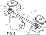
- Figures 2 to 4 show an air insulated or mixed air and gas insulated switchgear assembly 1.
- the gas is an arc extinguishing gas such as SF 6 or such as a mixture of fluoronitrile, fluoroketones, carbon dioxide and /or dioxygen.
- the switchgear assembly 1 comprises an air insulated or mixed air and gas insulated switchgear 2 for each phase of an AC electric line, an earthing switch 10 for each phase of the AC electric line, a ground connection 9 and fasteners 20.
- Each switchgear 2 comprises a switchgear housing 3, a central conductor 7 and insulator walls 6.
- Figure 3 shows more specifically a switchgear 2 and an earthing switch 10 of one of the phases of the AC electric line.
- the switchgear housing 3 encloses a gas chamber 2a which is filled by air or a mix of air and gas.
- the switchgear housing 3 comprises a mounting flange 8 to which the earthing switch 10 is fixed.
- the switchgear housing 3 surrounds the central conductor 7.
- the switchgear housing 3 is connected to the ground independently from the earthing switch 10.
- the central conductor 7 comprises electrically active parts of the switchgear 2.
- the central conductor 7 extends longitudinally along the longitudinal direction X-X of the switchgear.
- the insulator walls 6 each hold the central conductor 2 relative to the switchgear housing 3.
- the insulator walls 6 each extend radially relative to the longitudinal direction X-X of the switchgear between the central conductor 7 and the switchgear housing 3.
- each earthing switch 10 comprises a switch housing 13, a movable contact rod 12, a drive mechanism 11, a fixed electrical contact 14 and an insulator flange 16.
- Each earthing switch 10 is configured to ground the central conductor 7 of the switchgear 2 of the corresponding phase.
- the longitudinal direction Y-Y of the earthing switch is substantially perpendicular to the longitudinal direction X-X of the switchgear of the corresponding phase.
- the switch housing 13 encloses at least part of the movable contact rod 12 and at least part of the drive mechanism 11.
- the switch housing 13 is fixed to the switchgear housing 13 by the insulator flange 16 and by the fasteners 20.
- the fixed electrical contact 14 is fixed to the central conductor 7.
- the fixed electrical contact 14 is for example a tulip type female conductor.
- the fixed electrical contact 14 may comprise contact fingers for grasping the movable contact rod 14.
- the movable contact rod 12 is annular along the longitudinal direction Y-Y of the earthing switch.
- the movable contact rod 12 is movable along the longitudinal direction Y-Y of the earthing switch relative to the switch housing 13 and to the fixed electrical contact 14 between an elongated position and a retracted position.
- the movable contact rod 12 in the elongated position electrically and mechanically engages the fixed electrical contact 14.
- the earthing switch 10 is in a closed position.
- the movable contact rod 12 in the retracted position is electrically disconnected from the fixed electrical contact.
- the earthing switch 10 is an opened position.
- the drive mechanism 11 is configured to move the movable contact rod 12 relative to the switch housing 13 and to the fixed electrical contact 14 between the elongated position and the retracted position with a drive movement 11a along the longitudinal direction Y-Y of the earthing switch.
- the insulator flange 16 comprises a metallic body and a dielectric insulating layer.
- the switch housing 13 is mechanically connected to the switchgear housing 3 through the insulator flange 16.
- the insulator flange 16 electrically insulates the switchgear housing 3 from the switch housing 13.
- the electrically insulating layer covers entirely the metallic body in the disclosed embodiment.
- the electrically insulating layer forms the entire external surface of the insulator flange 16 in the disclosed embodiment.
- the insulator layer comprises an oxidation layer.
- the oxidation layer is made from the same metallic material as the metallic material of the metallic body of the insulator flange 16.
- the oxidation layer is made by anodic oxidation of the metallic body of the insulator flange 16.
- the metallic body is for example made of aluminum and the oxidation layer is for example made by hard anodization of the metallic body.
- the oxidation layer is in particular made of alumina in that case.
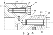
- the fasteners 20 include first fasteners 21, 23, 27 and second fasteners 22, 25, 29.
- the fasteners 20 fasten the switch housing 13 to the switchgear housing 3 through the insulator flange 16.
- the first fasteners 21, 23, 27 are arranged in a first circular row for fastening the switch housing 13 to the insulator flange 16.
- the first fasteners each include a metallic screw 21, a metallic washer 23 and a metallic peg 29 in the disclosed embodiment.
- the second fasteners 22, 25, 29 are arranged in a second circular row concentric with the first circular row and radially spaced from the first circular row.
- the second fasteners 22, 25, 29 fasten the insulator flange 16 to the switchgear housing 3.
- the second fasteners 22, 23, 25 are insulated fasteners 22, 25, 29.
- the second fasteners each include a metallic screw 22, a dielectric insulating washer 25 and a dielectric insulating peg 29.
- the dielectric insulating washer 25 are each made of a material containing plastic.
- the dielectric insulating peg 29 are also made of a material containing plastic.
- the dielectric insulating washer 25 and dielectric insulating peg 29 are configured to limit wear of the insulating layer. They also contribute to electrically insulating the switchgear housing 3 from the switch housing 13.
- the ground connection comprises an earthing frame 9.
- the ground connection 9 is configured to electrically insulate the switchgear housing 3 from the switch housing 13 together with the insulator flange 16.
- the ground connection 9 is configured to electrically connect the switch housing 13 to the ground, when the earthing switch 10 is in the opened position and when the earthing switch 10 is in the closed position.
- the ground connection 9 is electrically disconnected from the switchgear housing 3.
- the earthing frame 9 is secured to the earthing switch 10 housing 13 of each phase.
- the earthing frame 9 comprises earthing rods 90 and an earth connection 91.
- the earthing rods 90 each extend between two earthing switch housings 13 of two different phases of the switchgear assembly 1.
- the earth connection 91 connects the earthing rods 90 to the ground independently from each switchgear housing 3.
- the ground connection 9 is electrically connected to the central conductor 7, to the movable contact rod 12 and to the switch housing 13, when the earthing switch 10 is in the closed position.
- each earthing switch 10 is closed and each movable rod 12 is in the elongated position.
- the ground connection 9 is electrically connected to the movable contact rod 12 and to the switch housing 13, when the earthing switch 10 is in the opened position.
- each earthing switch 10 is opened and each movable rod 12 is in the retracted position.
- the central conductor 7 of each switchgear 2 is under medium to high voltage and/or current.
- each earthing switch 10 has a higher resilience to outdoor applications.
- the insulator flange 16 has high mechanical resistance and it will not break easily.
- the insulator flange 16 may be easily recycled.
- the earthing switch 10 has thus higher environmental durability.
- the insulator flange 16 may be deprived of electrically insulating layer near the fasteners 20. At the very least, the electrically insulating layer covers the metallic body at least on a first contact surface of the insulator flange 16 with the switchgear housing 3. In addition or alternatively, the electrically insulating layer covers the metallic body at least on a second contact surface of the insulator flange 16 with the switch housing 13.
- the insulator layer may comprise a dielectric coating, instead of and in addition to the oxidation layer.
- the oxidation layer may be made of another metallic material from the metallic material of the metallic body of the insulator flange 16, for example when the oxidation layer is deposited or cladded onto the metallic body.
- the fasteners 20 may include a rivet, a pin and/or a nut and in addition to or instead of screws and pegs.
- the first fasteners 21, 23, 27 may be insulated fasteners and/or the second fasteners 22, 23, 25 may be non-insulated metallic fasteners.
Landscapes
- Engineering & Computer Science (AREA)
- Power Engineering (AREA)
- Gas-Insulated Switchgears (AREA)
Abstract
Description
- The invention belongs to the field of medium to high-voltage technology, i.e. 52 kV or higher. In particular, the invention relates to electrical insulation for air-insulated switchgear assemblies (AIS) or mixed air and gas insulated switchgear assemblies.
-
Figure 1 shows an existing gas insulatedswitchgear assembly 5. Such a gas insulated assembly has to withstand higher voltage than an air-insulated switchgear assembly or a mixed switchgear assembly. - The gas insulated
switchgear assembly 5 comprises aninsulating earthing switch 15 and a gas insulatedswitchgear 2. Theearthing switch 15 is separated from thehousing 3 of the gas insulatedswitchgear 2 by aninsulator 17 which is made of plastic material such as an epoxy resin. - During normal operation, the
earthing switch 5 is electrically connected to the gas insulatedswitchgear 2 by aground connection 19. Theground connection 19 is a short circuit bridge between anearthing switch housing 13 and aswitch gear housing 3. - For measurements in which a measured signal is applied to or tapped off over the contact system of the
insulating earthing switch 15, theground connection 19 is removed. - Such an existing insulated earthing switch has a limited resilience to outdoor application. In particular, the insulator of the earthing switch has limited mechanical resistance and it may break. Besides, the earthing switch has limited environmental durability because of the plastic material insulator.
- The invention relates to an air insulated or mixed air and gas insulated switchgear assembly. The switchgear assembly comprises an air insulated or mixed air and gas insulated switchgear and an earthing switch. The switchgear comprises a switchgear housing and a central conductor extending within the switchgear housing. The earthing switch comprises a switch housing, a movable contact rod and a fixed electrical contact. The fixed electrical contact is secured to the central conductor. The movable contact rod is movable relative to the switch housing and to the fixed electrical contact.
- The movable contact rod electrically engages the fixed electrical contact when the earthing switch is in a closed position. The movable contact rod is electrically disconnected from the fixed electrical contact when the earthing switch is an opened position.
- According to the invention, the earthing switch comprises an insulator flange comprising a metallic body and a dielectric insulating layer on the metallic body, and the switch housing is mechanically connected to the switchgear housing through the insulator flange.
- Thanks to the insulator flange of the gas insulated switchgear assembly of the invention, the earthing switch has a higher resilience to outdoor applications. In particular, the insulator flange has high mechanical resistance and it will not break easily. The insulator flange may be easily recycled. The insulated earthing switch has higher environmental durability.
- Preferred features of the invention are recited in the dependent claims.
- This invention will be better understood after reading the following description of example embodiments that are in no way limitative, wherein:
-
Figure 1 schematically and partially shows a known gas insulated switchgear assembly in longitudinal cross section; -
Figure 2 schematically shows a portion of a gas insulated switchgear assembly according to a first embodiment of the invention in a perspective view; -
Figure 3 schematically shows a portion of the gas insulated switchgear assembly according to a first embodiment of the invention in longitudinal cross section; -
Figure 4 schematically shows a portion of the connection between a switchgear and an earthing switch of the switchgear assembly according to the first embodiment and in cross section; -
Figure 5a is a schematic circuit diagram of the gas insulated switchgear assembly of the first embodiment when the earthing switch is in a closed position; -
Figure 5b is a schematic circuit diagram of the gas insulated switchgear assembly of the first embodiment in an opened position during normal operation of the switchgear assembly; -
Figures 2 to 4 show an air insulated or mixed air and gas insulatedswitchgear assembly 1. The gas is an arc extinguishing gas such as SF6 or such as a mixture of fluoronitrile, fluoroketones, carbon dioxide and /or dioxygen. - The
switchgear assembly 1 comprises an air insulated or mixed air and gas insulatedswitchgear 2 for each phase of an AC electric line, anearthing switch 10 for each phase of the AC electric line, aground connection 9 andfasteners 20. - Each
switchgear 2 comprises aswitchgear housing 3, acentral conductor 7 andinsulator walls 6. -
Figure 3 shows more specifically aswitchgear 2 and anearthing switch 10 of one of the phases of the AC electric line. - With reference to
Figure 3 , theswitchgear housing 3 encloses agas chamber 2a which is filled by air or a mix of air and gas. Theswitchgear housing 3 comprises amounting flange 8 to which theearthing switch 10 is fixed. Theswitchgear housing 3 surrounds thecentral conductor 7. Theswitchgear housing 3 is connected to the ground independently from theearthing switch 10. - The
central conductor 7 comprises electrically active parts of theswitchgear 2. Thecentral conductor 7 extends longitudinally along the longitudinal direction X-X of the switchgear. - The
insulator walls 6 each hold thecentral conductor 2 relative to theswitchgear housing 3. Theinsulator walls 6 each extend radially relative to the longitudinal direction X-X of the switchgear between thecentral conductor 7 and theswitchgear housing 3. - With reference to
Figure 2 andfigure 3 , eachearthing switch 10 comprises aswitch housing 13, amovable contact rod 12, adrive mechanism 11, a fixedelectrical contact 14 and aninsulator flange 16. Eachearthing switch 10 is configured to ground thecentral conductor 7 of theswitchgear 2 of the corresponding phase. - In the disclosed embodiment, the longitudinal direction Y-Y of the earthing switch is substantially perpendicular to the longitudinal direction X-X of the switchgear of the corresponding phase.
- With reference to
Figure 3 , theswitch housing 13 encloses at least part of themovable contact rod 12 and at least part of thedrive mechanism 11. Theswitch housing 13 is fixed to theswitchgear housing 13 by theinsulator flange 16 and by thefasteners 20. - The fixed
electrical contact 14 is fixed to thecentral conductor 7. The fixedelectrical contact 14 is for example a tulip type female conductor. In particular, the fixedelectrical contact 14 may comprise contact fingers for grasping themovable contact rod 14. - The
movable contact rod 12 is annular along the longitudinal direction Y-Y of the earthing switch. - The
movable contact rod 12 is movable along the longitudinal direction Y-Y of the earthing switch relative to theswitch housing 13 and to the fixedelectrical contact 14 between an elongated position and a retracted position. - The
movable contact rod 12 in the elongated position electrically and mechanically engages the fixedelectrical contact 14. When themovable contact rod 12 electrically engages the fixedelectrical contact 14, theearthing switch 10 is in a closed position. - The
movable contact rod 12 in the retracted position is electrically disconnected from the fixed electrical contact. When themovable contact rod 12 is electrically disconnected from the fixedelectrical contact 14, theearthing switch 10 is an opened position. - The
drive mechanism 11 is configured to move themovable contact rod 12 relative to theswitch housing 13 and to the fixedelectrical contact 14 between the elongated position and the retracted position with adrive movement 11a along the longitudinal direction Y-Y of the earthing switch. - The
insulator flange 16 comprises a metallic body and a dielectric insulating layer. Theswitch housing 13 is mechanically connected to theswitchgear housing 3 through theinsulator flange 16. Theinsulator flange 16 electrically insulates theswitchgear housing 3 from theswitch housing 13. - The electrically insulating layer covers entirely the metallic body in the disclosed embodiment. The electrically insulating layer forms the entire external surface of the
insulator flange 16 in the disclosed embodiment. - The insulator layer comprises an oxidation layer. In the first disclosed embodiment, the oxidation layer is made from the same metallic material as the metallic material of the metallic body of the
insulator flange 16. - The oxidation layer is made by anodic oxidation of the metallic body of the
insulator flange 16. The metallic body is for example made of aluminum and the oxidation layer is for example made by hard anodization of the metallic body. The oxidation layer is in particular made of alumina in that case. - The
fasteners 20 includefirst fasteners second fasteners fasteners 20 fasten theswitch housing 13 to theswitchgear housing 3 through theinsulator flange 16. - The
first fasteners switch housing 13 to theinsulator flange 16. The first fasteners each include ametallic screw 21, ametallic washer 23 and ametallic peg 29 in the disclosed embodiment. - The
second fasteners second fasteners insulator flange 16 to theswitchgear housing 3. - The
second fasteners fasteners metallic screw 22, a dielectric insulatingwasher 25 and a dielectric insulatingpeg 29. - The dielectric insulating
washer 25 are each made of a material containing plastic. The dielectric insulatingpeg 29 are also made of a material containing plastic. The dielectric insulatingwasher 25 and dielectric insulatingpeg 29 are configured to limit wear of the insulating layer. They also contribute to electrically insulating theswitchgear housing 3 from theswitch housing 13. - The ground connection comprises an earthing
frame 9. Theground connection 9 is configured to electrically insulate theswitchgear housing 3 from theswitch housing 13 together with theinsulator flange 16. - The
ground connection 9 is configured to electrically connect theswitch housing 13 to the ground, when the earthingswitch 10 is in the opened position and when the earthingswitch 10 is in the closed position. Theground connection 9 is electrically disconnected from theswitchgear housing 3. - The earthing
frame 9 is secured to the earthingswitch 10housing 13 of each phase. The earthingframe 9 comprises earthingrods 90 and anearth connection 91. - The earthing
rods 90 each extend between two earthingswitch housings 13 of two different phases of theswitchgear assembly 1. Theearth connection 91 connects the earthingrods 90 to the ground independently from eachswitchgear housing 3. - With reference to
Figure 5a , theground connection 9 is electrically connected to thecentral conductor 7, to themovable contact rod 12 and to theswitch housing 13, when the earthingswitch 10 is in the closed position. - During grounding operation of the
switchgear assembly 1, each earthingswitch 10 is closed and eachmovable rod 12 is in the elongated position. - With reference to
Figure 5b , theground connection 9 is electrically connected to themovable contact rod 12 and to theswitch housing 13, when the earthingswitch 10 is in the opened position. - During normal operation of the
switchgear assembly 1, each earthingswitch 10 is opened and eachmovable rod 12 is in the retracted position. Thecentral conductor 7 of eachswitchgear 2 is under medium to high voltage and/or current. - Thanks to each insulator flanges 16 of the gas insulated switchgear assembly, each earthing
switch 10 has a higher resilience to outdoor applications. In particular, theinsulator flange 16 has high mechanical resistance and it will not break easily. Theinsulator flange 16 may be easily recycled. The earthingswitch 10 has thus higher environmental durability. - The above described embodiments may of course be modified by the man of ordinary skill in the art.
- The
insulator flange 16 may be deprived of electrically insulating layer near thefasteners 20. At the very least, the electrically insulating layer covers the metallic body at least on a first contact surface of theinsulator flange 16 with theswitchgear housing 3. In addition or alternatively, the electrically insulating layer covers the metallic body at least on a second contact surface of theinsulator flange 16 with theswitch housing 13. - The insulator layer may comprise a dielectric coating, instead of and in addition to the oxidation layer.
- The oxidation layer may be made of another metallic material from the metallic material of the metallic body of the
insulator flange 16, for example when the oxidation layer is deposited or cladded onto the metallic body. - The
fasteners 20 may include a rivet, a pin and/or a nut and in addition to or instead of screws and pegs. - The
first fasteners second fasteners
Claims (10)
- An air insulated or mixed air and gas insulated switchgear assembly (1) comprising:an air insulated or mixed air and gas insulated switchgear (2) comprising a switchgear housing (3) and a central conductor (7) extending within the switchgear housing (3),an earthing switch (10) comprising a switch housing (13), a movable contact rod (12) and a fixed electrical contact (14),wherein the fixed electrical contact (14) is secured to the central conductor (7),wherein the movable contact rod (12) is movable relative to the switch housing (13) and to the fixed electrical contact (14),wherein the movable contact rod (12) electrically engages the fixed electrical contact (14) when the earthing switch (10) is in a closed position, and wherein the movable contact rod (12) is electrically disconnected from the fixed electrical contact (14) when the earthing switch (10) is an opened position,characterized in that the earthing switch (10) comprises an insulator flange (16) comprising a metallic body and a dielectric insulating layer on the metallic body, and in that the switch housing (13) is mechanically connected to the switchgear housing (3) through the insulator flange (16).
- The switchgear assembly (1) to the preceding claim, wherein the electrically insulating layer forms substantially the entire external surface of the insulator flange (16).
- The switchgear assembly (1) according to any one of the preceding claims, wherein the insulator layer comprises an oxidation layer,
wherein the oxidation layer is preferably made from the same metallic material as the metallic material of the metallic body. - The switchgear assembly (1) according to the preceding claim, wherein the oxidation layer is made by anodic oxidation of the metallic body of the insulator flange (16), preferably by hard anodization of the metallic body.
- The switchgear assembly (1) according to any one of the preceding claims, wherein the switchgear assembly (1) comprises fasteners (20) for fastening the switch housing (13) to the switchgear housing (3) through the insulator flange (16).
- The switchgear assembly (1) according to the preceding claim, wherein the fasteners (20) include first fasteners (21, 23, 27) arranged in a first annular row for fastening the switch housing (13) to the insulator flange (16), and
wherein the fasteners (20) include second fasteners (22, 25, 29) arranged in a second annular row concentric with the first annular row and radially spaced from the first annular row, wherein the second fasteners (22, 25, 29) fasten the insulator flange (16) to the switchgear housing (3). - The switchgear assembly (1) according to any one of the preceding claims 5 to 6, wherein the fasteners (20) include insulated fasteners (22, 25, 29) each including a metallic screw (22) and a dielectric insulating washer (25) made of a material containing plastic,
wherein the insulated fasteners (22, 25, 29) preferably each further include a dielectric insulating peg (29) made of a material containing plastic. - The switchgear assembly (1) according to any one of the preceding claims, wherein the switchgear assembly (1) comprises a ground connection (9) for electrically connecting the switch housing (13) to the ground, when the earthing switch (10) is in the opened position and when the earthing switch (10) is in the closed position.
- The switchgear assembly (1) according to the preceding claim, wherein the ground connection (9) is electrically connected the central conductor (7), to the movable contact rod (12) and to the switch housing (13) when the earthing switch (10) is in the closed position,
wherein the ground connection is electrically disconnected from the switchgear housing (3) when the earthing switch (10) is in the opened position. - The switchgear assembly (1) according to any one of the preceding claims 8 to 9, wherein the switchgear assembly (1) comprises an air insulated or mixed air and gas insulated switchgear (2) for each phase of an AC electric line,wherein the switchgear assembly (1) comprises an earthing switch (10) for each phase of an AC electric line,wherein each switchgear (2) includes a switchgear housing (3) and a central conductor (7) extending inside the switchgear housing (3),wherein each earthing switch (10) comprising a switch housing (13), a movable contact rod (12), a fixed electrical contact (14), and an insulator flange (16) comprising a metallic body and a dielectric insulating layer on the metallic body,wherein the ground connection comprises an earthing frame (9) secured to the earthing switch (10) housing (13) of each phase, wherein the earthing frame (9) comprises earthing rods (90) each extending between two earthing switch housings (13) of the switchgear assembly (1).
Priority Applications (5)
| Application Number | Priority Date | Filing Date | Title |
|---|---|---|---|
| EP22177030.8A EP4287232B1 (en) | 2022-06-02 | 2022-06-02 | Insulated earthing switch for an air insulated or mixed switchgear |
| US18/326,478 US12413053B2 (en) | 2022-06-02 | 2023-05-31 | Insulated earthing switch for an air insulated or mixed switchgear |
| BR102023010802-4A BR102023010802A2 (en) | 2022-06-02 | 2023-06-01 | SWITCH APPARATUS ASSEMBLY |
| CN202310648349.5A CN117175416A (en) | 2022-06-02 | 2023-06-02 | Insulated earthing switches for air-insulated or hybrid switchgear |
| CA3201784A CA3201784A1 (en) | 2022-06-02 | 2023-06-02 | Insulated earthing switch for an air insulated or mixed switchgear |
Applications Claiming Priority (1)
| Application Number | Priority Date | Filing Date | Title |
|---|---|---|---|
| EP22177030.8A EP4287232B1 (en) | 2022-06-02 | 2022-06-02 | Insulated earthing switch for an air insulated or mixed switchgear |
Publications (2)
| Publication Number | Publication Date |
|---|---|
| EP4287232A1 true EP4287232A1 (en) | 2023-12-06 |
| EP4287232B1 EP4287232B1 (en) | 2024-12-25 |
Family
ID=81877711
Family Applications (1)
| Application Number | Title | Priority Date | Filing Date |
|---|---|---|---|
| EP22177030.8A Active EP4287232B1 (en) | 2022-06-02 | 2022-06-02 | Insulated earthing switch for an air insulated or mixed switchgear |
Country Status (5)
| Country | Link |
|---|---|
| US (1) | US12413053B2 (en) |
| EP (1) | EP4287232B1 (en) |
| CN (1) | CN117175416A (en) |
| BR (1) | BR102023010802A2 (en) |
| CA (1) | CA3201784A1 (en) |
Citations (2)
| Publication number | Priority date | Publication date | Assignee | Title |
|---|---|---|---|---|
| EP1569256A1 (en) * | 2004-02-27 | 2005-08-31 | ABB Technology AG | Insulated earthing switch for GIS |
| EP2597662A1 (en) * | 2011-11-28 | 2013-05-29 | ABB Technology AG | Earth switch for gas-isolated medium or high voltage assembly |
Family Cites Families (7)
| Publication number | Priority date | Publication date | Assignee | Title |
|---|---|---|---|---|
| FR2129885B1 (en) * | 1971-03-18 | 1974-02-15 | Alsthom Cgee | |
| US3806682A (en) * | 1972-10-03 | 1974-04-23 | Bbc Brown Boveri & Cie | High-voltage gas-insulated switchgear with capacitive voltage divider for indicating contact position |
| JPS5857226A (en) * | 1981-09-30 | 1983-04-05 | 株式会社日立製作所 | Ground switch |
| JP4230739B2 (en) * | 2002-08-29 | 2009-02-25 | 三菱電機株式会社 | Gas insulated switchgear |
| DE102009022105A1 (en) * | 2009-05-20 | 2010-11-25 | Abb Technology Ag | Gas-insulated high-voltage switchgear |
| DE102010004981B3 (en) * | 2010-01-18 | 2011-07-21 | Abb Technology Ag | Metal-enclosed, gas-insulated combined disconnector and earthing switch |
| WO2019150508A1 (en) * | 2018-01-31 | 2019-08-08 | 三菱電機株式会社 | Gas-insulated switching apparatus |
-
2022
- 2022-06-02 EP EP22177030.8A patent/EP4287232B1/en active Active
-
2023
- 2023-05-31 US US18/326,478 patent/US12413053B2/en active Active
- 2023-06-01 BR BR102023010802-4A patent/BR102023010802A2/en unknown
- 2023-06-02 CN CN202310648349.5A patent/CN117175416A/en active Pending
- 2023-06-02 CA CA3201784A patent/CA3201784A1/en active Pending
Patent Citations (2)
| Publication number | Priority date | Publication date | Assignee | Title |
|---|---|---|---|---|
| EP1569256A1 (en) * | 2004-02-27 | 2005-08-31 | ABB Technology AG | Insulated earthing switch for GIS |
| EP2597662A1 (en) * | 2011-11-28 | 2013-05-29 | ABB Technology AG | Earth switch for gas-isolated medium or high voltage assembly |
Also Published As
| Publication number | Publication date |
|---|---|
| BR102023010802A2 (en) | 2023-12-12 |
| CA3201784A1 (en) | 2023-12-02 |
| CN117175416A (en) | 2023-12-05 |
| EP4287232B1 (en) | 2024-12-25 |
| US12413053B2 (en) | 2025-09-09 |
| US20230396043A1 (en) | 2023-12-07 |
Similar Documents
| Publication | Publication Date | Title |
|---|---|---|
| US4748304A (en) | Electrical circuit breaker with improved dielectric withstand | |
| EP2214191B1 (en) | Gas-insulated equipment | |
| US20110036811A1 (en) | Switchgear and Method for Operating Switchgear | |
| CN101409175A (en) | Combined high-voltage load switch and high-voltage switchgear thereof | |
| US4837662A (en) | Gas insulated switchgear | |
| US4468716A (en) | Gas-insulated switchgear | |
| JP2000268685A (en) | Switchgear | |
| JP2009022115A (en) | Solid insulation switchgear and test method thereof | |
| EP4287232B1 (en) | Insulated earthing switch for an air insulated or mixed switchgear | |
| EP3840144B1 (en) | Switch device | |
| US10763062B2 (en) | Switching device with dual conductive housing | |
| US7485807B2 (en) | Gas-insulated bus bar component comprising outdoor bushings | |
| JPH11164429A (en) | Disconnector with grounding device | |
| JP3712456B2 (en) | Gas insulated disconnect switch | |
| JP2003281981A (en) | Vacuum switchgear | |
| JPWO2000024016A1 (en) | Vacuum switches and vacuum switchgear | |
| JP3369319B2 (en) | Disconnector with resistance | |
| JP3202302B2 (en) | Metal closed switchgear | |
| JP6953936B2 (en) | Ground switchgear / lightning arrester unit and gas insulation switchgear | |
| JP2000050437A (en) | Gas insulated switchgear | |
| EP3876256B1 (en) | Switching device for electric power distribution | |
| JPH07230731A (en) | Gas insulated switchgear and gas insulated bushing | |
| JP3408269B2 (en) | Disconnector with resistance | |
| JPH1075519A (en) | Gas insulation device | |
| JPH0210725Y2 (en) |
Legal Events
| Date | Code | Title | Description |
|---|---|---|---|
| PUAI | Public reference made under article 153(3) epc to a published international application that has entered the european phase |
Free format text: ORIGINAL CODE: 0009012 |
|
| STAA | Information on the status of an ep patent application or granted ep patent |
Free format text: STATUS: THE APPLICATION HAS BEEN PUBLISHED |
|
| AK | Designated contracting states |
Kind code of ref document: A1 Designated state(s): AL AT BE BG CH CY CZ DE DK EE ES FI FR GB GR HR HU IE IS IT LI LT LU LV MC MK MT NL NO PL PT RO RS SE SI SK SM TR |
|
| RAP1 | Party data changed (applicant data changed or rights of an application transferred) |
Owner name: GENERAL ELECTRIC TECHNOLOGY GMBH |
|
| STAA | Information on the status of an ep patent application or granted ep patent |
Free format text: STATUS: REQUEST FOR EXAMINATION WAS MADE |
|
| 17P | Request for examination filed |
Effective date: 20240524 |
|
| RBV | Designated contracting states (corrected) |
Designated state(s): AL AT BE BG CH CY CZ DE DK EE ES FI FR GB GR HR HU IE IS IT LI LT LU LV MC MK MT NL NO PL PT RO RS SE SI SK SM TR |
|
| GRAP | Despatch of communication of intention to grant a patent |
Free format text: ORIGINAL CODE: EPIDOSNIGR1 |
|
| STAA | Information on the status of an ep patent application or granted ep patent |
Free format text: STATUS: GRANT OF PATENT IS INTENDED |
|
| INTG | Intention to grant announced |
Effective date: 20240924 |
|
| RIC1 | Information provided on ipc code assigned before grant |
Ipc: H01H 33/56 20060101ALN20240913BHEP Ipc: H01H 33/52 20060101ALN20240913BHEP Ipc: H01H 33/02 20060101ALN20240913BHEP Ipc: H01H 31/10 20060101ALI20240913BHEP Ipc: H01H 31/00 20060101AFI20240913BHEP |
|
| GRAS | Grant fee paid |
Free format text: ORIGINAL CODE: EPIDOSNIGR3 |
|
| GRAA | (expected) grant |
Free format text: ORIGINAL CODE: 0009210 |
|
| STAA | Information on the status of an ep patent application or granted ep patent |
Free format text: STATUS: THE PATENT HAS BEEN GRANTED |
|
| AK | Designated contracting states |
Kind code of ref document: B1 Designated state(s): AL AT BE BG CH CY CZ DE DK EE ES FI FR GB GR HR HU IE IS IT LI LT LU LV MC MK MT NL NO PL PT RO RS SE SI SK SM TR |
|
| REG | Reference to a national code |
Ref country code: GB Ref legal event code: FG4D |
|
| REG | Reference to a national code |
Ref country code: CH Ref legal event code: EP |
|
| REG | Reference to a national code |
Ref country code: DE Ref legal event code: R096 Ref document number: 602022009006 Country of ref document: DE |
|
| REG | Reference to a national code |
Ref country code: IE Ref legal event code: FG4D |
|
| REG | Reference to a national code |
Ref country code: SE Ref legal event code: TRGR |
|
| P01 | Opt-out of the competence of the unified patent court (upc) registered |
Free format text: CASE NUMBER: APP_7599/2025 Effective date: 20250214 |
|
| REG | Reference to a national code |
Ref country code: LT Ref legal event code: MG9D |
|
| PG25 | Lapsed in a contracting state [announced via postgrant information from national office to epo] |
Ref country code: FI Free format text: LAPSE BECAUSE OF FAILURE TO SUBMIT A TRANSLATION OF THE DESCRIPTION OR TO PAY THE FEE WITHIN THE PRESCRIBED TIME-LIMIT Effective date: 20241225 |
|
| PG25 | Lapsed in a contracting state [announced via postgrant information from national office to epo] |
Ref country code: BG Free format text: LAPSE BECAUSE OF FAILURE TO SUBMIT A TRANSLATION OF THE DESCRIPTION OR TO PAY THE FEE WITHIN THE PRESCRIBED TIME-LIMIT Effective date: 20241225 |
|
| PG25 | Lapsed in a contracting state [announced via postgrant information from national office to epo] |
Ref country code: NO Free format text: LAPSE BECAUSE OF FAILURE TO SUBMIT A TRANSLATION OF THE DESCRIPTION OR TO PAY THE FEE WITHIN THE PRESCRIBED TIME-LIMIT Effective date: 20250325 |
|
| PG25 | Lapsed in a contracting state [announced via postgrant information from national office to epo] |
Ref country code: LV Free format text: LAPSE BECAUSE OF FAILURE TO SUBMIT A TRANSLATION OF THE DESCRIPTION OR TO PAY THE FEE WITHIN THE PRESCRIBED TIME-LIMIT Effective date: 20241225 Ref country code: GR Free format text: LAPSE BECAUSE OF FAILURE TO SUBMIT A TRANSLATION OF THE DESCRIPTION OR TO PAY THE FEE WITHIN THE PRESCRIBED TIME-LIMIT Effective date: 20250326 |
|
| PG25 | Lapsed in a contracting state [announced via postgrant information from national office to epo] |
Ref country code: RS Free format text: LAPSE BECAUSE OF FAILURE TO SUBMIT A TRANSLATION OF THE DESCRIPTION OR TO PAY THE FEE WITHIN THE PRESCRIBED TIME-LIMIT Effective date: 20250325 |
|
| REG | Reference to a national code |
Ref country code: NL Ref legal event code: MP Effective date: 20241225 |
|
| PG25 | Lapsed in a contracting state [announced via postgrant information from national office to epo] |
Ref country code: NL Free format text: LAPSE BECAUSE OF FAILURE TO SUBMIT A TRANSLATION OF THE DESCRIPTION OR TO PAY THE FEE WITHIN THE PRESCRIBED TIME-LIMIT Effective date: 20241225 |
|
| REG | Reference to a national code |
Ref country code: AT Ref legal event code: MK05 Ref document number: 1754929 Country of ref document: AT Kind code of ref document: T Effective date: 20241225 |
|
| PG25 | Lapsed in a contracting state [announced via postgrant information from national office to epo] |
Ref country code: SM Free format text: LAPSE BECAUSE OF FAILURE TO SUBMIT A TRANSLATION OF THE DESCRIPTION OR TO PAY THE FEE WITHIN THE PRESCRIBED TIME-LIMIT Effective date: 20241225 |
|
| PG25 | Lapsed in a contracting state [announced via postgrant information from national office to epo] |
Ref country code: PL Free format text: LAPSE BECAUSE OF FAILURE TO SUBMIT A TRANSLATION OF THE DESCRIPTION OR TO PAY THE FEE WITHIN THE PRESCRIBED TIME-LIMIT Effective date: 20241225 |
|
| PG25 | Lapsed in a contracting state [announced via postgrant information from national office to epo] |
Ref country code: ES Free format text: LAPSE BECAUSE OF FAILURE TO SUBMIT A TRANSLATION OF THE DESCRIPTION OR TO PAY THE FEE WITHIN THE PRESCRIBED TIME-LIMIT Effective date: 20241225 |
|
| PG25 | Lapsed in a contracting state [announced via postgrant information from national office to epo] |
Ref country code: IS Free format text: LAPSE BECAUSE OF FAILURE TO SUBMIT A TRANSLATION OF THE DESCRIPTION OR TO PAY THE FEE WITHIN THE PRESCRIBED TIME-LIMIT Effective date: 20250425 |
|
| PG25 | Lapsed in a contracting state [announced via postgrant information from national office to epo] |
Ref country code: PT Free format text: LAPSE BECAUSE OF FAILURE TO SUBMIT A TRANSLATION OF THE DESCRIPTION OR TO PAY THE FEE WITHIN THE PRESCRIBED TIME-LIMIT Effective date: 20250428 |
|
| PG25 | Lapsed in a contracting state [announced via postgrant information from national office to epo] |
Ref country code: EE Free format text: LAPSE BECAUSE OF FAILURE TO SUBMIT A TRANSLATION OF THE DESCRIPTION OR TO PAY THE FEE WITHIN THE PRESCRIBED TIME-LIMIT Effective date: 20241225 |
|
| PG25 | Lapsed in a contracting state [announced via postgrant information from national office to epo] |
Ref country code: RO Free format text: LAPSE BECAUSE OF FAILURE TO SUBMIT A TRANSLATION OF THE DESCRIPTION OR TO PAY THE FEE WITHIN THE PRESCRIBED TIME-LIMIT Effective date: 20241225 Ref country code: AT Free format text: LAPSE BECAUSE OF FAILURE TO SUBMIT A TRANSLATION OF THE DESCRIPTION OR TO PAY THE FEE WITHIN THE PRESCRIBED TIME-LIMIT Effective date: 20241225 |
|
| PG25 | Lapsed in a contracting state [announced via postgrant information from national office to epo] |
Ref country code: SK Free format text: LAPSE BECAUSE OF FAILURE TO SUBMIT A TRANSLATION OF THE DESCRIPTION OR TO PAY THE FEE WITHIN THE PRESCRIBED TIME-LIMIT Effective date: 20241225 |
|
| PG25 | Lapsed in a contracting state [announced via postgrant information from national office to epo] |
Ref country code: CZ Free format text: LAPSE BECAUSE OF FAILURE TO SUBMIT A TRANSLATION OF THE DESCRIPTION OR TO PAY THE FEE WITHIN THE PRESCRIBED TIME-LIMIT Effective date: 20241225 |
|
| RAP4 | Party data changed (patent owner data changed or rights of a patent transferred) |
Owner name: GE VERNOVA TECHNOLOGY GMBH |
|
| REG | Reference to a national code |
Ref country code: DE Ref legal event code: R097 Ref document number: 602022009006 Country of ref document: DE |
|
| PG25 | Lapsed in a contracting state [announced via postgrant information from national office to epo] |
Ref country code: DK Free format text: LAPSE BECAUSE OF FAILURE TO SUBMIT A TRANSLATION OF THE DESCRIPTION OR TO PAY THE FEE WITHIN THE PRESCRIBED TIME-LIMIT Effective date: 20241225 |
|
| PGFP | Annual fee paid to national office [announced via postgrant information from national office to epo] |
Ref country code: CH Payment date: 20250701 Year of fee payment: 4 |
|
| PLBE | No opposition filed within time limit |
Free format text: ORIGINAL CODE: 0009261 |
|
| STAA | Information on the status of an ep patent application or granted ep patent |
Free format text: STATUS: NO OPPOSITION FILED WITHIN TIME LIMIT |
|
| REG | Reference to a national code |
Ref country code: CH Ref legal event code: L10 Free format text: ST27 STATUS EVENT CODE: U-0-0-L10-L00 (AS PROVIDED BY THE NATIONAL OFFICE) Effective date: 20251105 |
|
| 26N | No opposition filed |
Effective date: 20250926 |
|
| PG25 | Lapsed in a contracting state [announced via postgrant information from national office to epo] |
Ref country code: MC Free format text: LAPSE BECAUSE OF FAILURE TO SUBMIT A TRANSLATION OF THE DESCRIPTION OR TO PAY THE FEE WITHIN THE PRESCRIBED TIME-LIMIT Effective date: 20241225 |
|
| PG25 | Lapsed in a contracting state [announced via postgrant information from national office to epo] |
Ref country code: LU Free format text: LAPSE BECAUSE OF NON-PAYMENT OF DUE FEES Effective date: 20250602 |
|
| REG | Reference to a national code |
Ref country code: BE Ref legal event code: MM Effective date: 20250630 |
|
| PG25 | Lapsed in a contracting state [announced via postgrant information from national office to epo] |
Ref country code: IE Free format text: LAPSE BECAUSE OF NON-PAYMENT OF DUE FEES Effective date: 20250602 |
|
| PG25 | Lapsed in a contracting state [announced via postgrant information from national office to epo] |
Ref country code: HR Free format text: LAPSE BECAUSE OF FAILURE TO SUBMIT A TRANSLATION OF THE DESCRIPTION OR TO PAY THE FEE WITHIN THE PRESCRIBED TIME-LIMIT Effective date: 20241225 |
|
| PG25 | Lapsed in a contracting state [announced via postgrant information from national office to epo] |
Ref country code: BE Free format text: LAPSE BECAUSE OF NON-PAYMENT OF DUE FEES Effective date: 20250630 |
|
| PG25 | Lapsed in a contracting state [announced via postgrant information from national office to epo] |
Ref country code: LT Free format text: LAPSE BECAUSE OF FAILURE TO SUBMIT A TRANSLATION OF THE DESCRIPTION OR TO PAY THE FEE WITHIN THE PRESCRIBED TIME-LIMIT Effective date: 20241225 |
|
| REG | Reference to a national code |
Ref country code: CH Ref legal event code: U11 Free format text: ST27 STATUS EVENT CODE: U-0-0-U10-U11 (AS PROVIDED BY THE NATIONAL OFFICE) Effective date: 20260701 |
|
| PGFP | Annual fee paid to national office [announced via postgrant information from national office to epo] |
Ref country code: IT Payment date: 20260520 Year of fee payment: 5 |
|
| PGFP | Annual fee paid to national office [announced via postgrant information from national office to epo] |
Ref country code: DE Payment date: 20260520 Year of fee payment: 5 |
|
| PGFP | Annual fee paid to national office [announced via postgrant information from national office to epo] |
Ref country code: SE Payment date: 20260520 Year of fee payment: 5 |
|
| PGFP | Annual fee paid to national office [announced via postgrant information from national office to epo] |
Ref country code: FR Payment date: 20260521 Year of fee payment: 5 |
|
| PG25 | Lapsed in a contracting state [announced via postgrant information from national office to epo] |
Ref country code: CY Free format text: LAPSE BECAUSE OF FAILURE TO SUBMIT A TRANSLATION OF THE DESCRIPTION OR TO PAY THE FEE WITHIN THE PRESCRIBED TIME-LIMIT Effective date: 20241225 |