EP4287221A1 - Heat transfer from transformer windings - Google Patents
Heat transfer from transformer windings Download PDFInfo
- Publication number
- EP4287221A1 EP4287221A1 EP22275073.9A EP22275073A EP4287221A1 EP 4287221 A1 EP4287221 A1 EP 4287221A1 EP 22275073 A EP22275073 A EP 22275073A EP 4287221 A1 EP4287221 A1 EP 4287221A1
- Authority
- EP
- European Patent Office
- Prior art keywords
- bobbin
- transformer
- openings
- core
- winding
- Prior art date
- Legal status (The legal status is an assumption and is not a legal conclusion. Google has not performed a legal analysis and makes no representation as to the accuracy of the status listed.)
- Pending
Links
- 238000004804 winding Methods 0.000 title claims abstract description 44
- 238000012546 transfer Methods 0.000 title description 5
- 239000004020 conductor Substances 0.000 claims abstract description 13
- 238000004519 manufacturing process Methods 0.000 claims description 6
- 238000000034 method Methods 0.000 claims description 6
- 239000000654 additive Substances 0.000 claims description 3
- 230000000996 additive effect Effects 0.000 claims description 3
- 239000003822 epoxy resin Substances 0.000 claims description 2
- 229920000647 polyepoxide Polymers 0.000 claims description 2
- 229910010293 ceramic material Inorganic materials 0.000 claims 1
- 238000013461 design Methods 0.000 description 10
- 238000001816 cooling Methods 0.000 description 6
- 239000007769 metal material Substances 0.000 description 4
- 230000004907 flux Effects 0.000 description 3
- 238000006243 chemical reaction Methods 0.000 description 2
- 230000017525 heat dissipation Effects 0.000 description 2
- 239000011551 heat transfer agent Substances 0.000 description 2
- 230000008569 process Effects 0.000 description 2
- 239000007787 solid Substances 0.000 description 2
- 238000010146 3D printing Methods 0.000 description 1
- CWYNVVGOOAEACU-UHFFFAOYSA-N Fe2+ Chemical compound [Fe+2] CWYNVVGOOAEACU-UHFFFAOYSA-N 0.000 description 1
- 208000021017 Weight Gain Diseases 0.000 description 1
- 239000000919 ceramic Substances 0.000 description 1
- 230000001808 coupling effect Effects 0.000 description 1
- 230000007423 decrease Effects 0.000 description 1
- 238000011161 development Methods 0.000 description 1
- 230000018109 developmental process Effects 0.000 description 1
- 238000005516 engineering process Methods 0.000 description 1
- 230000002708 enhancing effect Effects 0.000 description 1
- 230000020169 heat generation Effects 0.000 description 1
- 239000000463 material Substances 0.000 description 1
- 230000004048 modification Effects 0.000 description 1
- 238000012986 modification Methods 0.000 description 1
- 239000004033 plastic Substances 0.000 description 1
- 229920003023 plastic Polymers 0.000 description 1
- 230000009467 reduction Effects 0.000 description 1
- 230000004584 weight gain Effects 0.000 description 1
- 235000019786 weight gain Nutrition 0.000 description 1
Images

Classifications
-
- H—ELECTRICITY
- H01—ELECTRIC ELEMENTS
- H01F—MAGNETS; INDUCTANCES; TRANSFORMERS; SELECTION OF MATERIALS FOR THEIR MAGNETIC PROPERTIES
- H01F5/00—Coils
- H01F5/02—Coils wound on non-magnetic supports, e.g. formers
-
- H—ELECTRICITY
- H01—ELECTRIC ELEMENTS
- H01F—MAGNETS; INDUCTANCES; TRANSFORMERS; SELECTION OF MATERIALS FOR THEIR MAGNETIC PROPERTIES
- H01F27/00—Details of transformers or inductances, in general
- H01F27/08—Cooling; Ventilating
- H01F27/22—Cooling by heat conduction through solid or powdered fillings
-
- H—ELECTRICITY
- H01—ELECTRIC ELEMENTS
- H01F—MAGNETS; INDUCTANCES; TRANSFORMERS; SELECTION OF MATERIALS FOR THEIR MAGNETIC PROPERTIES
- H01F27/00—Details of transformers or inductances, in general
- H01F27/24—Magnetic cores
-
- H—ELECTRICITY
- H01—ELECTRIC ELEMENTS
- H01F—MAGNETS; INDUCTANCES; TRANSFORMERS; SELECTION OF MATERIALS FOR THEIR MAGNETIC PROPERTIES
- H01F27/00—Details of transformers or inductances, in general
- H01F27/28—Coils; Windings; Conductive connections
- H01F27/2876—Cooling
-
- H—ELECTRICITY
- H01—ELECTRIC ELEMENTS
- H01F—MAGNETS; INDUCTANCES; TRANSFORMERS; SELECTION OF MATERIALS FOR THEIR MAGNETIC PROPERTIES
- H01F27/00—Details of transformers or inductances, in general
- H01F27/28—Coils; Windings; Conductive connections
- H01F27/32—Insulating of coils, windings, or parts thereof
- H01F27/324—Insulation between coil and core, between different winding sections, around the coil; Other insulation structures
- H01F27/325—Coil bobbins
-
- H—ELECTRICITY
- H01—ELECTRIC ELEMENTS
- H01F—MAGNETS; INDUCTANCES; TRANSFORMERS; SELECTION OF MATERIALS FOR THEIR MAGNETIC PROPERTIES
- H01F30/00—Fixed transformers not covered by group H01F19/00
- H01F30/02—Auto-transformers
-
- H—ELECTRICITY
- H01—ELECTRIC ELEMENTS
- H01F—MAGNETS; INDUCTANCES; TRANSFORMERS; SELECTION OF MATERIALS FOR THEIR MAGNETIC PROPERTIES
- H01F41/00—Apparatus or processes specially adapted for manufacturing or assembling magnets, inductances or transformers; Apparatus or processes specially adapted for manufacturing materials characterised by their magnetic properties
- H01F41/02—Apparatus or processes specially adapted for manufacturing or assembling magnets, inductances or transformers; Apparatus or processes specially adapted for manufacturing materials characterised by their magnetic properties for manufacturing cores, coils, or magnets
- H01F41/04—Apparatus or processes specially adapted for manufacturing or assembling magnets, inductances or transformers; Apparatus or processes specially adapted for manufacturing materials characterised by their magnetic properties for manufacturing cores, coils, or magnets for manufacturing coils
- H01F41/12—Insulating of windings
Definitions
- the present disclosure is concerned with enhancing or improving the transfer of heat generated in a transformer away from the transformer coils, and particularly from the windings of auto-transformer rectifier units (ATRUs).
- ATRUs auto-transformer rectifier units
- Transformers are used in many electrical systems to transform voltage or current at one level to voltage and/or current at a different level.
- a transformer consists of one or more windings or coils of conductive material wound around a ferrous or magnetic core such that current flow through one winding or part of a winding will induce current flow through another winding or part of a winding.
- Many systems e.g. power converters used in applications such as aircraft, convert AC power to DC power to drive DC loads. To reduce harmonics in such systems, it has become common to use autotransformers which only have a single winding acting as both the primary and the secondary winding of the system. Auto-transformers are used, for example, in power conversion systems on aircraft to provide power to the various electric loads.
- the size and weight of the transformer is an important factor, whilst ensuring high performance and efficiency.
- Developments in transformer technology enable relatively small transformer designs to be highly effective and efficient in power conversion and noise reduction.
- a limiting factor, however, in reducing component size is the heat generated in the transformer. Core losses and winding losses cause more heat to be generated in the transformer. Further, the greater the density of the windings, the greater the resistance to the heat generated in the innermost windings, which, if not effectively dissipated, causes a rise in the overall temperature of the transformer, which can damage parts and is a fire risk. In addition, as operating temperature increases, the saturation flux density of the core decreases. High levels of heat generation, therefore, reduce the efficiency, safety and life of the transformer.
- Natural cooling methods although inexpensive, are not typically very effective and can lead to bulky designs. Active cooling methods are more effective, but require additional cooling systems and energy and can be expensive. For these reasons, it is common for transformers to be designed to be larger than is actually necessary to produce the required power and voltage, because the larger size enables heat to be dissipated more effectively and reduces the above risks. There has to be a trade-off, therefore, between safety and operating performance on the one hand and miniaturisation on the other.
- US 2013/0293330 improves the heat transfer from the innermost winding layer, where the peak temperatures are often associated, to pass through to the transformer core, from where heat can be more easily dissipated, using a laminated-metallic thermally conductive bobbin onto which the windings are wound.
- the conductive properties of the metallic bobbin disrupts the transformer electromagnetic flux flow, which directly affects its electrical performance.
- a bobbin for receiving a transformer winding, the bobbin comprising a non-metallic tubular body having at least one wall having an outer surface onto which the transformer winding is wound, in use, and an inner surface defining a passage to receive a transformer core, in use, the bobbin comprising a plurality of openings formed through the wall(s) from the outer surface to the inner surface, and further comprising a thermally conductive material provided in the openings.
- a typical transformer is shown.
- the example shown is a three-phase transformer having three sets of windings each wound around a bobbin (in the drawing reference numeral 1 represents the combination of the bobbins and the windings) and a magnetic core assembly around which the windings are provided.
- the number of phases can, however, vary.
- the windings are wound around the bobbin which is fitted around the core.
- the core assembly comprises two opposing E shaped core elements 2 (known as an EE transformer core), which defines three core legs each having a set of coils, on a bobbin, provided therearound.
- Other core designs such a E cores or toroidal cores are also known in the art.
- the windings are formed by coils of conductive wires but other forms of conductor could be used to form the winding.
- An insulating cover (not shown) is typically formed around the windings on the bobbin.
- the bobbin is typically formed as a tubular body having walls having an outer surface onto which the winding is wound, and an inner surface defining a passage to receive the core.
- the shape and dimensions of the body will depend on the transformer design including the shape and design of the core. In the example shown, the bobbins have a square or rectangular cross-section but other shapes can be envisaged.
- the conductors forming the windings have a large number of closely wound turns to provide the required power/voltage and this results in the generation of heat in the windings, particularly the innermost windings closest to the bobbin body.
- the solution provided by the present disclosure provides a modified bobbin such that heat can be more easily transferred from the winding without increasing the overall size and weight of the assembly and without affecting the flow of electromagnetic flux of the transformer.
- the modification involves forming the bobbin of a non-metallic material and providing openings in the wall of the bobbin body. A thermally conductive material is provided in the openings.
- non-metallic materials can be used for the bobbin, including plastics.
- the bobbin can be formed by additive manufacturing or 3D printing processes to simplify the manufacture of various shapes and sizes of the bobbin and of the openings.
- the use of non-metallic materials can also reduce the cost and/or the weight of the bobbin.
- the thermally conductive material can be one of many known heat transfer agents such as epoxy resin or a fine ceramic and can either fill or partially fill or line the openings.
- the thermally conductive material in the openings acts as a heat transfer agent through the bobbin and, further, means that air cannot become trapped in the openings and so the problem of an insulating air trap between the core and the winding is avoided.
- the openings can be provided at locations along the line and around the body of the bobbin, according to the transformer design and requirements.
- the number, size and shape of the openings can also be selected as required.
- the openings may be in the form of rectangular slots or may be in the form of larger rectangular openings or windows (here, we refer to a 'slot' as an opening which is elongate and has a length dimension substantially larger than a width direction, whereas a 'window' is a wider form of slot).
- Other shapes e.g. circular, oval etc. openings may also be envisaged.
- the bobbin may have various tubular shapes, e.g. rectangular in cross-section, square, circular, oval or other shape.
- the wall will be formed of four sides.
- the openings may be provided in all four sides or only some sides. Different shaped openings could be provided on different sides or in different portions of the sides.
- openings may be provided at selected locations and may have selected shapes, sizes and numbers.
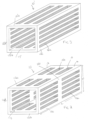
- Figure 2 shows a bobbin 10 having a rectangular cross-section defined by four sides - a top side 12a, a bottom side 12b, a right side 12c and a left side 12d (from the point of view of the Figure).
- the sides together form the bobbin wall 12, the inner surface 13 of which defines a passage for receiving the core (e.g. a core 2 such as shown in Fig. 1 ).
- the outer surface 14 of the wall is the surface that, in use, is in contact with the winding (not shown here) wound around the bobbin 10.
- the bobbin is formed of a non-metallic material to match the transformer core around which it is to be placed.
- the openings 15 are formed through the wall 12 of the bobbin at selected locations.
- elongate slots 15a are formed in the right and left side walls.
- the number of slots can, of course, be varied.
- the openings 15b on the top side 12a are wider than the slots 15a in the side wall and could be referred to as 'windows'.
- Figure 3 shows an alternative design of a bobbin 10', again having four walls 12'a, 12'b, 12'c and 12'd, the inner surfaces 13' defining a passage, but where the slots are not split into several slots in the length L direction but, rather, a single slot 16a extends along the length of the wall(s).
- openings are a design choice and involves a trade-off between greater heat dissipation (more/bigger openings) and structural strength and integrity of the bobbin (more solid wall). Providing more openings may also be more difficult and expensive to manufacture, although this is less so if additive manufacturing processes are used.
- a thermally conductive material is provided in the openings 15. This may be provided in the openings by e.g. a known resin-penetration process for the whole transformer
- the modified bobbin may be used for all types of transformer having windings provided around a core, and has been found to provide particular heat transfer improvements in 12-pulse and 18-pulse auto-transformers.
- the concept applied to modify the bobbin is applicable to all known core designs, including E, EE, U, I, C etc. cores.
Abstract
A bobbin for receiving a transformer winding, the bobbin comprising a non-metallic tubular body (10) having at least one wall (12) having an outer surface (14) onto which the transformer winding is wound, in use, and an inner surface (13) defining a passage to receive a transformer core, in use, the bobbin comprising a plurality of openings (15) formed through the wall(s) from the outer surface to the inner surface, and further comprising a thermally conductive material provided in the openings.
Description
- The present disclosure is concerned with enhancing or improving the transfer of heat generated in a transformer away from the transformer coils, and particularly from the windings of auto-transformer rectifier units (ATRUs).
- Transformers are used in many electrical systems to transform voltage or current at one level to voltage and/or current at a different level. A transformer consists of one or more windings or coils of conductive material wound around a ferrous or magnetic core such that current flow through one winding or part of a winding will induce current flow through another winding or part of a winding. Many systems e.g. power converters used in applications such as aircraft, convert AC power to DC power to drive DC loads. To reduce harmonics in such systems, it has become common to use autotransformers which only have a single winding acting as both the primary and the secondary winding of the system. Auto-transformers are used, for example, in power conversion systems on aircraft to provide power to the various electric loads.
- In many applications, the size and weight of the transformer is an important factor, whilst ensuring high performance and efficiency. Developments in transformer technology enable relatively small transformer designs to be highly effective and efficient in power conversion and noise reduction. A limiting factor, however, in reducing component size, is the heat generated in the transformer. Core losses and winding losses cause more heat to be generated in the transformer. Further, the greater the density of the windings, the greater the resistance to the heat generated in the innermost windings, which, if not effectively dissipated, causes a rise in the overall temperature of the transformer, which can damage parts and is a fire risk. In addition, as operating temperature increases, the saturation flux density of the core decreases. High levels of heat generation, therefore, reduce the efficiency, safety and life of the transformer. Natural cooling methods, although inexpensive, are not typically very effective and can lead to bulky designs. Active cooling methods are more effective, but require additional cooling systems and energy and can be expensive. For these reasons, it is common for transformers to be designed to be larger than is actually necessary to produce the required power and voltage, because the larger size enables heat to be dissipated more effectively and reduces the above risks. There has to be a trade-off, therefore, between safety and operating performance on the one hand and miniaturisation on the other.
-
US 9,230,726 -
US 2013/0293330 improves the heat transfer from the innermost winding layer, where the peak temperatures are often associated, to pass through to the transformer core, from where heat can be more easily dissipated, using a laminated-metallic thermally conductive bobbin onto which the windings are wound. The conductive properties of the metallic bobbin, however, disrupts the transformer electromagnetic flux flow, which directly affects its electrical performance. - There is, therefore, a need for improving heat dissipation in transformers to allow them to be made smaller, without the above disadvantages.
- According to the invention, there is provided a bobbin for receiving a transformer winding, the bobbin comprising a non-metallic tubular body having at least one wall having an outer surface onto which the transformer winding is wound, in use, and an inner surface defining a passage to receive a transformer core, in use, the bobbin comprising a plurality of openings formed through the wall(s) from the outer surface to the inner surface, and further comprising a thermally conductive material provided in the openings.
- Also provided is a transformer and a method of forming a bobbin and a transformer.
- Examples according to the disclosure will now be described with reference to the drawings. It should be noted that these are examples only, and variations are possible within the scope of the claims.
-
Figure 1 shows a typical 3-phase transformer design. -
Figure 2 shows an example of a bobbin according to the disclosure. -
Figure 3 shows an alternative bobbin according to the disclosure. - Referring to
Fig. 1 , a typical transformer is shown. The example shown is a three-phase transformer having three sets of windings each wound around a bobbin (in the drawing reference numeral 1 represents the combination of the bobbins and the windings) and a magnetic core assembly around which the windings are provided. The number of phases can, however, vary. The windings are wound around the bobbin which is fitted around the core. In this example, the core assembly comprises two opposing E shaped core elements 2 (known as an EE transformer core), which defines three core legs each having a set of coils, on a bobbin, provided therearound. Other core designs such a E cores or toroidal cores are also known in the art. In one example, the windings are formed by coils of conductive wires but other forms of conductor could be used to form the winding. An insulating cover (not shown) is typically formed around the windings on the bobbin. - The bobbin is typically formed as a tubular body having walls having an outer surface onto which the winding is wound, and an inner surface defining a passage to receive the core. The shape and dimensions of the body will depend on the transformer design including the shape and design of the core. In the example shown, the bobbins have a square or rectangular cross-section but other shapes can be envisaged.
- As mentioned above, typically, the conductors forming the windings have a large number of closely wound turns to provide the required power/voltage and this results in the generation of heat in the windings, particularly the innermost windings closest to the bobbin body.
- The solution provided by the present disclosure provides a modified bobbin such that heat can be more easily transferred from the winding without increasing the overall size and weight of the assembly and without affecting the flow of electromagnetic flux of the transformer.
- The modification involves forming the bobbin of a non-metallic material and providing openings in the wall of the bobbin body. A thermally conductive material is provided in the openings.
- Various non-metallic materials can be used for the bobbin, including plastics. Depending on the choice of material, the bobbin can be formed by additive manufacturing or 3D printing processes to simplify the manufacture of various shapes and sizes of the bobbin and of the openings. The use of non-metallic materials can also reduce the cost and/or the weight of the bobbin.
- The thermally conductive material can be one of many known heat transfer agents such as epoxy resin or a fine ceramic and can either fill or partially fill or line the openings. The thermally conductive material in the openings acts as a heat transfer agent through the bobbin and, further, means that air cannot become trapped in the openings and so the problem of an insulating air trap between the core and the winding is avoided.
- The openings can be provided at locations along the line and around the body of the bobbin, according to the transformer design and requirements. The number, size and shape of the openings can also be selected as required. For example, the openings may be in the form of rectangular slots or may be in the form of larger rectangular openings or windows (here, we refer to a 'slot' as an opening which is elongate and has a length dimension substantially larger than a width direction, whereas a 'window' is a wider form of slot). Other shapes e.g. circular, oval etc. openings may also be envisaged.
- As with the known examples described above, the bobbin may have various tubular shapes, e.g. rectangular in cross-section, square, circular, oval or other shape. For rectangular or square shapes, for example, the wall will be formed of four sides. The openings may be provided in all four sides or only some sides. Different shaped openings could be provided on different sides or in different portions of the sides. Similarly, for more rounded bobbins, openings may be provided at selected locations and may have selected shapes, sizes and numbers.
- Examples of modified bobbins according to the disclosure will be described with reference to
Figs. 2 and 3 . -
Figure 2 shows abobbin 10 having a rectangular cross-section defined by four sides - a top side 12a, a bottom side 12b, a right side 12c and a left side 12d (from the point of view of the Figure). The sides together form thebobbin wall 12, theinner surface 13 of which defines a passage for receiving the core (e.g. a core 2 such as shown inFig. 1 ). Theouter surface 14 of the wall is the surface that, in use, is in contact with the winding (not shown here) wound around thebobbin 10. - The bobbin is formed of a non-metallic material to match the transformer core around which it is to be placed.
- The
openings 15 are formed through thewall 12 of the bobbin at selected locations. In the example ofFig. 2 ,elongate slots 15a are formed in the right and left side walls. In this example, there are two columns of four slots - i.e. in the length direction L, there are two slots spaced by asolid portion 120 of wall, with four sets of slots in the width W direction. The number of slots can, of course, be varied. Also in the example ofFig. 2 , theopenings 15b on the top side 12a are wider than theslots 15a in the side wall and could be referred to as 'windows'. In this example, there are two sets of three spaced apart windows formed through the wall. Again, the number and sizes of the openings can be varied. In other examples (not shown here) not all of the walls may be provided with openings. -
Figure 3 shows an alternative design of a bobbin 10', again having four walls 12'a, 12'b, 12'c and 12'd, the inner surfaces 13' defining a passage, but where the slots are not split into several slots in the length L direction but, rather, a single slot 16a extends along the length of the wall(s).. - The choice of number and size and shapes of openings is a design choice and involves a trade-off between greater heat dissipation (more/bigger openings) and structural strength and integrity of the bobbin (more solid wall). Providing more openings may also be more difficult and expensive to manufacture, although this is less so if additive manufacturing processes are used.
- To enhance the dissipation of heat through the bobbin to the core 2, to improve heat transfer from the windings, especially the inner windings, a thermally conductive material is provided in the
openings 15. This may be provided in the openings by e.g. a known resin-penetration process for the whole transformer - The modified bobbin may be used for all types of transformer having windings provided around a core, and has been found to provide particular heat transfer improvements in 12-pulse and 18-pulse auto-transformers. As mentioned above, the concept applied to modify the bobbin is applicable to all known core designs, including E, EE, U, I, C etc. cores.
Claims (14)
- A bobbin for receiving a transformer winding, the bobbin comprising a non-metallic tubular body (10) having at least one wall (12) having an outer surface (14) onto which the transformer winding is wound, in use, and an inner surface (13) defining a passage to receive a transformer core, in use, the bobbin comprising a plurality of openings (15) formed through the wall(s) from the outer surface to the inner surface, and further comprising a thermally conductive material provided in the openings.
- The bobbin of claim 1 or 2, wherein at least some of the plurality of openings have an elongate cross-section.
- The bobbin of claim 1 or 2, wherein the bobbin has a rectangular cross-section formed by four walls.
- The bobbin of claim 2, wherein openings (15) are provided in one or more of the four walls.
- The bobbin of claim 4, wherein at least some of the plurality of openings have a shape different than others of the plurality of openings.
- The bobbin of any preceding claim, wherein the thermally conductive material is an epoxy resin.
- The bobbin of any of claims 1 to 5, wherein the thermally conductive material is a ceramic material.
- The bobbin of any preceding claim, formed by an additive manufacturing process.
- A transformer comprising:
a transformer core assembly, at least one bobbin as claimed in any preceding claim provided around the core assembly, and a conductive winding wound around each bobbin. - The transformer of claim 9, wherein the transformer core assembly comprises a plurality of core legs, the transformer comprises a bobbin as claimed in any of claims 1 to 8 around each of said core legs.
- The transformer of claim 10, wherein the core assembly is an E-shaped or EE-shaped core.
- The transformer of any of claims 9 to 11, being an auto-transformer.
- A method of forming a bobbin for receiving a transformer winding, comprising additively manufacturing a tubular bobbin body having openings formed therein through a wall of the tubular bobbin body, and providing a thermally conductive material in the openings.
- A method of forming a transformer, the method comprising providing a bobbin as claimed in any of claims 1 to 8, winding a transformer winding around the bobbin, locating the bobbin around a core assembly of the transformer.
Priority Applications (2)
| Application Number | Priority Date | Filing Date | Title |
|---|---|---|---|
| EP22275073.9A EP4287221A1 (en) | 2022-06-02 | 2022-06-02 | Heat transfer from transformer windings |
| US18/205,087 US20230395313A1 (en) | 2022-06-02 | 2023-06-02 | Heat transfer from transformer windings |
Applications Claiming Priority (1)
| Application Number | Priority Date | Filing Date | Title |
|---|---|---|---|
| EP22275073.9A EP4287221A1 (en) | 2022-06-02 | 2022-06-02 | Heat transfer from transformer windings |
Publications (1)
| Publication Number | Publication Date |
|---|---|
| EP4287221A1 true EP4287221A1 (en) | 2023-12-06 |
Family
ID=81940596
Family Applications (1)
| Application Number | Title | Priority Date | Filing Date |
|---|---|---|---|
| EP22275073.9A Pending EP4287221A1 (en) | 2022-06-02 | 2022-06-02 | Heat transfer from transformer windings |
Country Status (2)
| Country | Link |
|---|---|
| US (1) | US20230395313A1 (en) |
| EP (1) | EP4287221A1 (en) |
Citations (6)
| Publication number | Priority date | Publication date | Assignee | Title |
|---|---|---|---|---|
| DE8133597U1 (en) * | 1980-11-25 | 1982-04-22 | Legrand, 87000 Limoges | BOBBIN FOR TRANSFORMERS |
| JP2008153293A (en) * | 2006-12-14 | 2008-07-03 | Komatsu Ltd | Transformer |
| US20130293330A1 (en) | 2012-05-07 | 2013-11-07 | Delta Electronics, Inc. | Magnetic device having thermally-conductive bobbin |
| JP2013229353A (en) * | 2012-04-24 | 2013-11-07 | Tabuchi Electric Co Ltd | Electromagnetic inductor |
| US9230726B1 (en) | 2015-02-20 | 2016-01-05 | Crane Electronics, Inc. | Transformer-based power converters with 3D printed microchannel heat sink |
| DE102021104224A1 (en) * | 2020-03-10 | 2021-09-16 | Schaeffler Technologies AG & Co. KG | Structure test coil and method for producing a structure test coil |
-
2022
- 2022-06-02 EP EP22275073.9A patent/EP4287221A1/en active Pending
-
2023
- 2023-06-02 US US18/205,087 patent/US20230395313A1/en active Pending
Patent Citations (6)
| Publication number | Priority date | Publication date | Assignee | Title |
|---|---|---|---|---|
| DE8133597U1 (en) * | 1980-11-25 | 1982-04-22 | Legrand, 87000 Limoges | BOBBIN FOR TRANSFORMERS |
| JP2008153293A (en) * | 2006-12-14 | 2008-07-03 | Komatsu Ltd | Transformer |
| JP2013229353A (en) * | 2012-04-24 | 2013-11-07 | Tabuchi Electric Co Ltd | Electromagnetic inductor |
| US20130293330A1 (en) | 2012-05-07 | 2013-11-07 | Delta Electronics, Inc. | Magnetic device having thermally-conductive bobbin |
| US9230726B1 (en) | 2015-02-20 | 2016-01-05 | Crane Electronics, Inc. | Transformer-based power converters with 3D printed microchannel heat sink |
| DE102021104224A1 (en) * | 2020-03-10 | 2021-09-16 | Schaeffler Technologies AG & Co. KG | Structure test coil and method for producing a structure test coil |
Also Published As
| Publication number | Publication date |
|---|---|
| US20230395313A1 (en) | 2023-12-07 |
Similar Documents
| Publication | Publication Date | Title |
|---|---|---|
| US6750749B2 (en) | Amorphous metal core transformer | |
| US9633776B2 (en) | Variable core electromagnetic device | |
| EP2444983A2 (en) | Liquid cooled magnetic component with indirect cooling for high frequency and high power applications | |
| US8686820B2 (en) | Reactor | |
| KR102086355B1 (en) | Linear electromagnetic device | |
| US4897626A (en) | Cooling electromagnetic devices | |
| US7911308B2 (en) | Low thermal impedance conduction cooled magnetics | |
| EP1829063A1 (en) | Two part transformer core, transformer and method of manufacture | |
| KR20230004410A (en) | An inductive device | |
| EP3657518B1 (en) | Electromagnetic device with thermally conductive former | |
| KR101066144B1 (en) | Transformers | |
| EP4287221A1 (en) | Heat transfer from transformer windings | |
| WO2022136634A1 (en) | A coil and a transformer that have improved electromagnetic shielding | |
| JP2008270347A (en) | Transformer | |
| JP2016157915A (en) | Transformer for reducing eddy current losses of coil | |
| EP4303897A1 (en) | Magnetic core | |
| CN211858327U (en) | Inductance structure, reactance device and transformer device | |
| CA2332363C (en) | Inductance arrangement | |
| KR102555275B1 (en) | iron core structure of transformer | |
| EP4099346A1 (en) | Helicoidal guide for the cooling of a medium-frequency transformer | |
| KR200486562Y1 (en) | Oil immersed transformer having magnetic shield | |
| EP4113547A1 (en) | A transformer arrangement | |
| US20230008213A1 (en) | Electrotechnical device for an aircraft, comprising low-frequency coil components | |
| US20230033439A1 (en) | Electrotechnical device for an aircraft | |
| CN111524686A (en) | Inductance structure, reactance device and transformer device |
Legal Events
| Date | Code | Title | Description |
|---|---|---|---|
| PUAI | Public reference made under article 153(3) epc to a published international application that has entered the european phase |
Free format text: ORIGINAL CODE: 0009012 |
|
| STAA | Information on the status of an ep patent application or granted ep patent |
Free format text: STATUS: THE APPLICATION HAS BEEN PUBLISHED |
|
| AK | Designated contracting states |
Kind code of ref document: A1 Designated state(s): AL AT BE BG CH CY CZ DE DK EE ES FI FR GB GR HR HU IE IS IT LI LT LU LV MC MK MT NL NO PL PT RO RS SE SI SK SM TR |