EP4286824A2 - Tire testing device - Google Patents
Tire testing device Download PDFInfo
- Publication number
- EP4286824A2 EP4286824A2 EP23196877.7A EP23196877A EP4286824A2 EP 4286824 A2 EP4286824 A2 EP 4286824A2 EP 23196877 A EP23196877 A EP 23196877A EP 4286824 A2 EP4286824 A2 EP 4286824A2
- Authority
- EP
- European Patent Office
- Prior art keywords
- test wheel
- carriage
- road surface
- testing device
- frame
- Prior art date
- Legal status (The legal status is an assumption and is not a legal conclusion. Google has not performed a legal analysis and makes no representation as to the accuracy of the status listed.)
- Granted
Links
Images











Classifications
-
- G—PHYSICS
- G01—MEASURING; TESTING
- G01M—TESTING STATIC OR DYNAMIC BALANCE OF MACHINES OR STRUCTURES; TESTING OF STRUCTURES OR APPARATUS, NOT OTHERWISE PROVIDED FOR
- G01M17/00—Testing of vehicles
- G01M17/007—Wheeled or endless-tracked vehicles
- G01M17/02—Tyres
-
- G—PHYSICS
- G01—MEASURING; TESTING
- G01M—TESTING STATIC OR DYNAMIC BALANCE OF MACHINES OR STRUCTURES; TESTING OF STRUCTURES OR APPARATUS, NOT OTHERWISE PROVIDED FOR
- G01M17/00—Testing of vehicles
- G01M17/007—Wheeled or endless-tracked vehicles
- G01M17/02—Tyres
- G01M17/021—Tyre supporting devices, e.g. chucks
-
- B—PERFORMING OPERATIONS; TRANSPORTING
- B60—VEHICLES IN GENERAL
- B60C—VEHICLE TYRES; TYRE INFLATION; TYRE CHANGING; CONNECTING VALVES TO INFLATABLE ELASTIC BODIES IN GENERAL; DEVICES OR ARRANGEMENTS RELATED TO TYRES
- B60C19/00—Tyre parts or constructions not otherwise provided for
-
- B—PERFORMING OPERATIONS; TRANSPORTING
- B60—VEHICLES IN GENERAL
- B60C—VEHICLE TYRES; TYRE INFLATION; TYRE CHANGING; CONNECTING VALVES TO INFLATABLE ELASTIC BODIES IN GENERAL; DEVICES OR ARRANGEMENTS RELATED TO TYRES
- B60C25/00—Apparatus or tools adapted for mounting, removing or inspecting tyres
- B60C25/002—Inspecting tyres
-
- B—PERFORMING OPERATIONS; TRANSPORTING
- B60—VEHICLES IN GENERAL
- B60C—VEHICLE TYRES; TYRE INFLATION; TYRE CHANGING; CONNECTING VALVES TO INFLATABLE ELASTIC BODIES IN GENERAL; DEVICES OR ARRANGEMENTS RELATED TO TYRES
- B60C19/00—Tyre parts or constructions not otherwise provided for
- B60C2019/004—Tyre sensors other than for detecting tyre pressure
Definitions
- the present invention relates to tire testing devices.
- tire performance is influenced by conditions of road surfaces, the tire performance needs to be evaluated for road surfaces of various conditions.
- test tires are for example mounted to wheel rims of a test-dedicated vehicle and the test-dedicated vehicle is made to run on actual roads and an indoor test in which a testing device installed indoor is used are known.
- Patent Document 1 discloses an exemplary testing device to be used in the indoor tire test.
- the testing device disclosed in Patent Document 1 includes a rotating drum to which a simulated road surface is provided on its outer peripheral surface, and the test is performed by causing a test tire and the drum to rotate in a state where the test tire is made to contact with the simulated road surface.
- the indoor test is more accurate and more efficient than the on-road test.
- the conventional testing device for the indoor test since the simulated road surface is made to run at high speed during the test, it is difficult to perform the test in road surface conditions in which the road surface is covered with rain, snow, gravel or the like.
- the present invention is made in view of the foregoing circumstance, and the object of the present invention is to provide a tire testing device that is capable of performing the indoor test in various road surface conditions.
- a tire testing device including a road surface part having a road surface, and a carriage configured to rotatably hold a test wheel provided with a test tire and being capable of travelling along the road surface in a state where the test wheel is made to contact the road surface.
- a tire testing device including a road surface part having a road surface, and a carriage configured to rotatably hold a test wheel provided with a test tire and being capable of travelling along the road surface in a state where the test wheel is made to contact the road surface, at least a portion of the road surface part being configured from a replaceable road surface unit.
- a tire testing device including a carriage configured to rotatably hold a test wheel provided with a test tire and being capable of travelling along a road surface in a state where the test wheel is made to contact the road surface, and a driving system configured to drive the test wheel and the carriage.
- the driving system includes a carriage driving means configured to drive the carriage with respect to the road surface in a predetermined speed, a test wheel driving means configured to drive the test wheel in a rotating speed corresponding to the predetermined speed, a driving means configured to generate power to be used to drive the carriage and the test wheel, and a power distributing means configured to distribute power generated by the driving means to the carriage driving means and the test wheel driving means.
- a tire testing device including a carriage configured to rotatably hold a test wheel provided with a test tire and being capable of travelling along a road surface in a state where the test wheel is made to contact the road surface, and a driving system configured to drive the test wheel and the carriage.
- the driving system includes a driving means configured to generate power to be used to drive the carriage and the test wheel, and a first winding transmission mechanism configured to transmit the power generated by the driving means.
- the first winding transmission mechanism includes a drive pulley coupled to an output shaft of the driving means, a driven pulley held by the carriage and coupled to the test wheel, and a first winding intermediate node wound around the drive pulley and the driven pulley.
- the first winding intermediate node has a first portion and a second portion stretched in a travelling direction of the carriage and configured to be driven in directions opposite to each other, passes over the driven pulley at the first portion, and is fixed to the carriage at the second portion.
- a tire testing device including a carriage configured to rotatably hold a test wheel provided with a test tire and being capable of travelling on a base along a road surface in a state where the test wheel is made to contact the road surface, and a driving system configured to drive the test wheel and the carriage.
- the driving system includes a test wheel driving means configured to drive the test wheel.
- the test wheel driving means includes a rotational motion supplying means configured to supply rotational motion of a rotating speed corresponding to a speed of the carriage, and a torque applying means configured to apply a predetermined torque to the test wheel by changing a phase of the rotational motion supplied from the rotational motion supplying means.
- a tire testing device including a carriage configured to rotatably hold a test wheel provided with a test tire and being capable of travelling on a base along a road surface in a state where the test wheel is made to contact the road surface, and a driving system configured to drive the test wheel and the carriage.
- the driving system includes a test wheel driving means configured to drive the test wheel.
- the test wheel driving means includes two driving means configured to generate power for rotationally driving the test wheel, and a power coupling means configured to couple power generated by the two driving means.
- the two driving means includes a first motor mounted on the base, and a second motor mounted on the carriage.
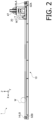
- Figs. 1 , 2 and 3 are a front view, a left side view and a plan view of a tire testing device 1 according to an embodiment of the present invention, respectively.
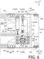
- Figs. 4 , 5 and 6 are a front view, a left side view and a plan view showing structures of and around a carriage 20 which will be described later, respectively.
- Figs. 4 to 6 for convenience of explanation, some components are omitted or shown in cross-sections.
- a direction from the right to the left is defined as an X axis direction
- a direction perpendicular to the paper from the back side to the front side is defined as a Y axis direction
- a direction from the bottom to the top is defined as a Z axis direction.
- the X axis direction and the Y axis direction are horizontal directions orthogonal to each other, and the Z axis direction is a vertical direction.
- a front-rear direction, an up-down direction and a left-right direction are defined as directions when facing a travelling direction of a carriage 20 (X axis positive direction).
- an X axis positive direction is defined as front
- an X axis negative direction is defined as rear
- a Y axis positive direction is defined as left
- a Y axis negative direction is defined as right
- a Z axis positive direction is defined as up
- a Z axis negative direction is defined as down.
- the tire testing device 1 includes a track part 10 and a road surface part 60 elongated in the X axis direction, and a carriage 20 that is capable of travelling on the track part 10 in the X axis direction.
- a track part 10 and a road surface part 60 elongated in the X axis direction
- a carriage 20 that is capable of travelling on the track part 10 in the X axis direction.
- an elongated space Sp1 extending over substantially the entire length of the track part 10 in the X axis direction is provided.
- the road surface part 60 is accommodated in this space Sp1.
- a road surface 63a (a paved part 63) with which a test tire T mounted to the carriage 20 contacts is provided.
- the track part 10 and the road surface part 60 are separated from each other.
- a base frame 11 hereinafter abbreviated to a "base 11" of the track part 10 and a frame 61 of the road surface part 60 may be integrally formed.
- a test wheel W (a wheel rim Wr to which the test tire T is mounted) is attached.
- the carriage 20 travels in a state where the test wheel W is in contact with the road surface 63a, and the test tire T rolls on the road surface 63a.
- the track part 10 includes a plurality of (in the present embodiment, three) linear guideways (hereinafter abbreviated to "linear guides") 13 configured to guide movement of the carriage 20 in the X axis direction, and one or more drive parts 14 configured to generate mechanical power for driving the carriage 20.
- linear guides two pairs of the drive parts 14 (a pair of drive parts 14LA and 14LB on the left and a pair of drive parts 14RA and 14RB on the right) are mounted on the base 11 of the track part 10 near four corners of the base 11.
- the drive parts 14LA and 14RA are arranged at a rear end portion of the track part 10
- the drive parts 14LB and 14RB are arranged at a front end portion of the track part 10.
- each drive part 14 includes a servo motor 141, and an optional reducer 142 configured to reduce rotating speed of output from the servo motor 141.
- the drive parts 14RA and 14RB on the right serve both as a carriage driving means for driving the carriage 20 to travel and as a rotational motion supplying means for supplying, to the test wheel W, rotational motion of rotating speed corresponding to a travelling speed of the carriage.
- the drive parts 14LA and 14LB on the left serve as carriage driving means.
- a super-low inertia and high-power type AC servo motor with an inertia moment of a rotating part being equal to or less than 0.01 kg•m 2 (preferably equal to or less than 0.008 kg•m 2 ) and with a rated power of 3 to 60 kW (7 to 37 kW being more suitable for practical use) is used.
- the tire testing device 1 includes a pair of belt mechanisms 50 (50L, 50R) on each of the left side and the right side.
- the belt mechanisms 50 transmit power generated by the drive parts 14 to the carriage 20 and drives the carriage 20 in the X axis direction.
- Each belt mechanism 50 includes a toothed belt 51, a pair of drive pulleys 52 (52A, 52B), and three driven pulleys 53 (53A, 53B, 53C).
- the drive pulleys 52 and the driven pulleys 53 are toothed pulleys that engage with the toothed belt 51.
- the toothed belt 51 has core wires made of steel wires. It should be noted that a toothed belt having core wires made of so-called super fiber such as carbon fiber, aramid fiber or ultra-high molecular weight polyethylene fiber may be used as the toothed belt 51.
- super fiber such as carbon fiber, aramid fiber or ultra-high molecular weight polyethylene fiber
- By the use of light-weight and high-strength core wires such as carbon core wires it becomes possible to drive the carriage 20 at high acceleration (or to apply high driving/braking force to the test wheel W) using a motor of relatively low output power, and thus it becomes possible to downsize the tire testing device 1 (or to make capacity of the tire testing device 1 large).
- the belt mechanism 50R on the right serves both as a carriage driving means for driving the carriage 20 to travel and as a primary power transmitting part for transmitting power supplied from the rotational motion supplying means (drive parts 14RA, 14RB) to a secondary power transmitting part which will be described later.
- the belt mechanism 50L on the left serves as a carriage driving means.
- the toothed belt 51 of the belt mechanism 50L [50R] on the left [right] is wound around the pair of drive pulleys 52 (52A, 52B) and the three driven pulleys 53 (53A, 53B, 53C).
- the pair of drive pulleys 52A, 52B are respectively coupled to output shafts of the pair of drive parts 14LA, 14LB [14RA, 14RB] on the left [right].
- the three driven pulleys 53A, 53B, 53C are attached to a driven part 22L [22R] on the left [right] which will be described later.
- each toothed belt 51 are fixed to a main frame 21 of the carriage 20 with respective belt clamps 54 (54A, 54B), thereby each toothed belt 51 forming a loop via the carriage 20.
- the pair of drive pulleys 52A, 52B ( Fig. 2 ) of the belt mechanism 50 are fixed pulleys that are arranged across an area through which the carriage 20 can travel and that are held on the base 11 (i.e., pulleys whose respective centers of gravity are fixed with respect to the base 11).
- the driven pulleys 53 are moving pulleys that are held on the carriage 20 and can move together with the carriage 20.
- the pair of drive parts 14LA, 14LB [14RA, 14RB] are driven in the same phase. Effective diameters (i.e., pitch circle diameters) or numbers of teeth of the drive pulleys 52 and the driven pulleys 53 are the same.
- the drive parts 14LA, 14LB on the left and the drive parts 14RA, 14RB on the right are mounted with the left side and the right side reversed and are driven in opposite phases.
- the toothed belt 51L [51R] is driven by the drive parts 14LA, 14LB [14RA, 14RB]
- the carriage 20 is pulled by the toothed belt 51L [51R] and is driven in the X axis direction.
- the track part 10 includes a plurality of (in the present embodiment, three) linear guides 13 (13A, 13B, 13C).
- Each linear guide 13 includes a rail 131 extending in the X axis direction and forming a track, and one or more (in the present embodiment, thee) carriages (hereinafter referred to as "runners 132") that can travel on the rail 131.
- Each rail 131 is laid on an upper surface of the base 11 of the track part 10.
- the rails 131 of the two linear guides 13A, 13B are arranged along both ends of the space Sp1 in the left-right direction and the rail 131 of the remaining linear guide 13C is arranged along a right end of the base 11, and the three rails 131 are attached to the base 11.
- Each runner 132 is attached on a lower surface of the carriage 20.
- the carriage 20 includes the main frame 21, driven parts 22L, 22R configured to respectively hold the driven pulleys 53 of the belt mechanisms 50L, 50R, a spindle part 28 ( Fig. 4 ) configured to rotatably hold the test wheel W to which the test tire T is mounted, an alignment part 40 configured to be capable of adjusting alignment of the test wheel W with respect to the road surface 63a and load on the road surface 63a, and a spindle driving mechanism 20D configured to rotationally drive a spindle 280 of the spindle part 28.
- the spindle 280 is an axle to which the test wheel W is to be mounted.
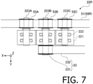
- Fig. 7 is a cross-sectional view showing an outline of a structure of the driven part 22R on the right.
- the driven part 22R includes a frame 221, three sets of bearings 222, and three shafts 223A-C. Three through holes extending in the Y axis direction are formed to the frame 221, and each of the shafts 223A-C is rotatably supported by a set of the bearings 222 fitted in respective through holes.
- each of the shafts 223A-C is supported by a pair of the bearings 222, but each of the shafts 223A-C may be supported by one bearing 222 or three or more bearings 222.
- driven pulleys 53A-C of the belt mechanism 50R are respectively attached.
- the shaft 223B at the center in the X axis direction is longer than the other two (the shafts 223A, 223C), and the other end portion of the shaft 223B is protruding from the other face of the frame 221.
- a drive pulley 231 of a belt mechanism 23 which will be described later is attached. That is, the belt mechanism 50R on the right and the belt mechanism 23 are coupled via the shaft 223B.
- the driven part 22L on the left has a configuration similar to the above-described driven part 22R on the right, but differs from the driven part 22R on the right in that the driven part 22L is arranged with the left side and the right side reversed and in that all the three shafts 223A-C are short and the driven pulley 231 is not attached to the other end portion of the shaft 223B.
- the spindle driving mechanism 20D includes the belt mechanism 23, a torque applying device 30, a belt mechanism 24, and a slide type constant velocity joint 25.
- Power transmitted from the belt mechanism 50R on the right to the belt mechanism 23 through the shaft 223B ( Fig. 7 ) of the driven part 22R on the right is transmitted to the spindle part 28 ( Fig. 4 ) through the torque applying device 30, the belt mechanism 24 and the slide type constant velocity joint 25, and rotationally drives the test wheel W mounted to the spindle part 28. That is, a portion of the power generated by the drive parts 14RA, 14RB on the right is used to drive the carriage 20, and the other portion of the power is used to rotationally drive the test wheel W.
- the belt mechanism 50R on the right serves as a means for driving the carriage 20 (the carriage driving means), as a means for driving the test wheel W (a test wheel driving means), and as a means for distributing the power generated by the drive parts 14RA, 14RB to the power for driving the carriage 20 and to the power for driving the test wheel W (a power distributing means).
- An upper portion 51a and a lower portion 51b of the toothed belt 51 of the belt mechanism 50 are stretched in the travelling direction of the carriage 20 and are driven in directions opposite to each other.
- the lower portion 51b of the toothed belt 51 which is fixed to the carriage 20 is driven in the travelling direction of the carriage along with the carriage 20, and the upper portion 51a is driven in a direction opposite to the travelling direction of the carriage 20 and the lower portion 51b.
- the upper portion 51a of the toothed belt 51 configured to travel in the direction opposite to the travelling direction of the carriage 20 is wound around the driven pulleys 53 attached to the carriage 20, and the driven pulleys 53 are driven by the upper portion 51a.
- the power applied to the driven pulley 53B is transmitted to the test wheel W through the secondary power transmitting part consisting of the belt mechanism 23, the torque applying device 30, the belt mechanism 24, the slide type constant velocity joint 25 and the spindle part 28, and is used to drive the test wheel W.
- the belt mechanism 50 By such configuration of the belt mechanism 50, it is made possible to drive both the carriage 20 and the test wheel W with the toothed belt 51.
- the configuration in which the carriage 20 and the test wheel W are driven by using rotational motion that is transmitted by a common power transmitting device i.e., the belt mechanism 50R
- a common power transmitting device i.e., the belt mechanism 50R
- the present embodiment is configured such that the test wheel W is rotationally driven in the peripheral speed that is substantially the same as the travelling speed of the carriage 20 when the torque applying device 30 is not active.
- Fig. 8 is a side cross-sectional view of the torque applying device 30.
- the torque applying device 30 generates torque to be applied to the test wheel W and outputs the torque by superposing on the rotational motion transmitted by the belt mechanism 23.
- the torque applying device 30 can apply the torque to the test wheel W (i.e., the torque applying device 30 can apply driving force or braking force between the road surface 63a and the test wheel W) by changing phase of the rotational motion transmitted by the belt mechanism 23.
- the torque applying device 30 By incorporating the torque applying device 30 in the spindle driving mechanism 20D, it becomes possible to divide roles between a power source (the drive parts 14RA, 14RB) for controlling the rotating speed and a power source (a servo motor 32 which will be described later) for controlling the torque. Due to this configuration, it becomes possible to use a power source of a smaller capacity and to control the rotating speed and the torque to be applied to the test wheel W with higher accuracy. Also, since torque that acts on the belt mechanism 50L decreases by incorporating the torque applying device 30 in the carriage 20, it becomes possible to downsize the belt mechanism 50L (e.g., decrease a number of toothed belts used) and to use members of lower load capacities.
- the torque applying device 30 includes a housing 31; a servo motor 32, a reducer 33 and a shaft 34 that are mounted inside the housing 31; two bearing parts 35, 36 configured to rotatably support the housing 31; a slip ring part 37; a columnar support 38 configured to support the slip ring part 37; and a rotary encoder 39.
- a rotating speed of the housing 31 is detected by the rotary encoder 39.
- a super-low inertia and high-power type AC servo motor with an inertia moment of a rotating part being equal to or less than 0.01 kg•m 2 and with a rated power of 7 to 37 kW is used.
- the housing 31 has a motor accommodating part 311 and a cap part 312 being substantially cylindrical and of large diameters, and a pair of shaft parts 313, 314 being substantially cylindrical and of diameters smaller than the motor accommodating part 311.
- the shaft part 313 is coaxially coupled (i.e., coupled in a manner such that the motor accommodating part 311 and the shaft part 313 share a center line).
- the shaft part 314 is coaxially coupled via the cap part 312.
- the shaft part 313 is rotatably supported by the bearing part 36, and the shaft part 314 is rotatably supported by the bearing part 35.
- a flange 314a is formed at a tip of the shaft part 314, and a driven pulley 232 of the belt mechanism 23 is coaxially coupled to the flange 314a.
- a toothed belt 233 of the belt mechanism 23 is wound around the driven pulley 232 and the drive pulley 231 ( Fig. 7 ).
- the housing 31 is rotationally driven by the belt mechanism 23.
- a bearing 315 is provided on an inner periphery of the shaft part 314.
- the shaft 34 is inserted in a hollow portion of the shaft part 314 and is rotatably supported by the bearing 315.
- the shaft 34 penetrates through the shaft part 314 and the driven pulley 232 and an end portion of the shaft 34 protrudes to the inside of the cap part 312.
- a drive pulley 241 of the belt mechanism 24 is coaxially coupled to the other end portion of the shaft 34 which penetrated through a hole 232a of the driven pulley 232.
- a toothed belt 243 is wound around the drive pulley 241.
- the servo motor 32 is accommodated in a hollow portion of the motor accommodating part 311.
- a shaft 321 of the servo motor 32 is arranged coaxially with the motor accommodating part 311, and a motor case 320 (i.e., a stator) of the servo motor 32 is fixed to the motor accommodating part 311 with a plurality of stud bolts 323.
- a flange 322 of the servo motor 32 is coupled to a gear case 331 of the reducer 33 via a coupling tube 324.
- the gear case 331 of the reducer 33 is fixed to an inner flange 312a of the cap part 312.
- the shaft 321 of the servo motor 32 is connected to an input shaft 332 of the reducer 33.
- the shaft 34 is connected to an output shaft 333 of the reducer 33.
- Torque that is output by the servo motor 32 is amplified by the reducer 33 and is transmitted to the shaft 34.
- Rotation output from the shaft 34 to the belt mechanism 24 is a superposition of the rotation of the housing 31 driven by the belt mechanism 23 and the torque generated by the servo motor 32 and the reducer 33. That is, the shaft part 314 of the housing 31 is an input shaft of the torque applying device 30, and the shaft 34 is an output shaft of the torque applying device 30.
- the torque applying device 30 outputs the torque generated by the torque applying device 30 through the output shaft by superposing the torque on the rotational motion transmitted to the input shaft.
- the slip ring part 37 includes a plurality of pairs of a slip ring 37a and a brush 37b, a supporting frame 37c and a coupling tube 37d.
- the plurality of slip rings 37a are arranged apart from each other and are fitted on an outer periphery of the coupling tube 37d.
- the coupling tube 37d is coaxially coupled to the shaft part 313 of the housing 31.
- the brushes 37b contacting outer peripheries of the corresponding slip rings 37a are supported by the supporting frame 37c attached to the columnar support 38.
- a cable 325 of the servo motor 32 passes through the hollow portion of the shaft part 313 and is connected to the slip rings 37a.
- the brushes 37b are connected to a servo amplifier 32a ( Fig. 10 ). That is, the servo motor 32 and the servo amplifier 32a are connected to each other via the slip ring part 37.
- the driven pulley 242 around which the toothed belt 243 of the belt mechanism 24 is wound is coaxially coupled to an end of a shaft 261 rotatably supported by the bearing part 262.
- the other end of the shaft 261 is connected to an end of the slide type constant velocity joint 25.
- the other end of the slide type constant velocity joint 25 is coupled to the spindle 280 via a shaft 263 and the like.
- the slide type constant velocity joint 25 is configured to be capable of transmitting rotation smoothly without rotation fluctuation regardless of an operating angle (an angle between the input shaft and the output shaft).
- the slide type constant velocity joint 25 is variable in length.
- the spindle 280 is supported by the alignment part 40 such that its angle and position of the input shaft is variable.
- the slide type constant velocity joint 25 By coupling the spindle 280 and the shaft 261 held by the bearing part 262 via the slide type constant velocity joint 25, even if the angle and/or position of the spindle 280 change, the slide type constant velocity joint 25 flexibly conforms to the change. Therefore, large strain does not occur to the spindle 280 and the shafts 261, 263 and thus rotation is smoothly transmitted to the spindle 280 without change in speed.
- the alignment part 40 includes a pair of pivoting frames 41, a pair of curved guideways 42 (hereinafter abbreviated to "curved guides"), a slide frame 44, and two pairs of linear guides 43.
- Each pivoting frame 41 is placed on the main frame 21 of the carriage 20 via the curved guide 42.
- the curved guide 42 includes an arc-like rail 421 attached on an upper surface of the main frame 21, and a plurality of (in the present embodiment, two) carriages 422 (hereinafter referred to as "runners 422") that can travel on the rail 421.
- the runners 422 are attached on a bottom surface of the pivoting frame 41.
- the pair of curved guides 42 and the pair of pivoting frames 41 are respectively arranged to oppose to each other in the front-rear direction across a vertical line V passing through a center C of the test wheel W.
- a center of curvature of each curved guide 42 is on the vertical line V. That is, each pivoting frame 41 is supported by the curved guide 42 to be pivotable about the vertical line V.
- the slide frame 44 has a column part 441, a coupling part 442, and a fork 443 in this order from the top.
- the column part 441 i.e., an upper portion of the slide frame 44
- the fork 443 i.e., a lower portion of the slide frame 44
- the coupling part 442 extends in the Y axis direction and couples a lower end portion of the column part 441 and an upper end portion of the fork 443 together. Therefore, the slide frame 44 is formed in a substantially crank shape when viewed in the X axis direction.
- a lower portion of the fork 443 is branched in the front-rear direction.
- respective bearings 443a are provided to be coaxial with respect to each other.
- Fig. 9 is a diagram showing structures of and around the spindle part 28.
- the spindle part 28 is arranged between a pair of the bearings 443a ( Fig. 5 ) provided to the lower end portions of the fork 443 while orienting a central axis (the rotation axis Ay) of the spindle 280 in the left-right direction.
- the spindle part 28 is supported by the pair of bearings 443a to be rotatable about a rotation axis Cx extending in the front-rear direction.
- the directions of the rotation axis Ay of the spindle 280 and the rotation axis Cx of a spindle case 284 change in accordance with the alignment of the spindle 280 and thus do not necessarily coincide with the Y axis direction and the X axis direction, respectively.
- the spindle part 28 includes the spindle 280, and the spindle case 284 configured to rotatably support the spindle 280.
- the spindle 280 includes a body part 281, a six force components sensor 282, and a hub 283.
- the body part 281 is a cylindrical shaft.
- the six force components sensor 282 is a substantially cylindrical member that is coaxially attached to a tip of the body part 281 and is a piezoelectric force sensor that is capable of detecting six force components (forces in the three axial directions orthogonal to each other and torques around respective axes).
- the hub 283 is a member for attaching the test wheel W and is coaxially attached to a tip of the six force components sensor 282.
- the body part 281, the six force components sensor 282 and the hub 283 are coupled integrally to form the spindle 280.
- the spindle 280 is an axle to which the test wheel W is to be mounted and that rotates integrally with the test wheel W. Since the test wheel W is integrally attached to the six force components sensor 282 via the hub 283, six force components acting on the test wheel W are detected by the six force components sensor 282.
- the spindle case 284 is a substantially cylindrical member configured to accommodate and rotatably hold the spindle 280.
- a bearing 285 and a pair of bearings 286 are attached on an inner periphery of the spindle case 284.
- the spindle 280 is rotatably supported by the bearing 285 and the bearings 286.
- a pair of pivots 287 which respectively rotatably fit to the pair of bearings 443a ( Fig. 5 ) of the fork 443 are attached. That is, the spindle part 28 is supported by the pair of bearings 443a to be rotatable about the rotation axis Cx.
- the alignment part 40 includes a load adjusting part 45, a slip angle adjusting part 46, and a camber adjusting part 47.
- the load adjusting part 45 is a unit configured to adjust load acting on the test wheel.
- the slip angle adjusting part 46 is a unit configured to adjust a slip angle of the test wheel W by causing the alignment part 40 (more specifically, the pivoting frame 41) to rotate about the vertical line V.
- the camber adjusting part 47 is a unit configured to adjust a camber angle of the test wheel W by causing the spindle part 28 to rotate about the rotation axis Cx ( Fig. 9 ).
- the load adjusting part 45 includes a servo motor 451, a motion converter 452, and a bracket 453.
- the above-described linear guide 43 may also be included in the load adjusting part 45.
- the servo motor 451 is attached to the main frame 21 of the carriage 20.
- the motion converter 452 is a device configured to convert rotational motion of the servo motor 451 into vertical linear motion of a vertically erected movable element 452a.
- As the motion converter 452 for example, a rack-and-pinion mechanism, a mechanism in which an intersecting shaft such as a bevel gear and a feed screw are combined, or a mechanism in which a skewed shaft such as a worm gear or a screw gear and a feed screw are combined is used.
- the bracket 453 is arranged right below the movable element 452a of the motion converter 452, and is attached to a side face of the column part 441 of the slide frame 44 while facing a flange 453a up.
- the movable element 452a of the motion converter 452 is caused to descend by driving the servo motor 451, a lower end of the movable element 452a abuts the flange 453a of the bracket 453.
- the slide frame 44 is pressed vertically downward by the movable element 452a via the bracket 453.
- the test wheel W held by the alignment part 40 is thereby pressed against the road surface 63a, and load depending on a height (i.e., a position in the Z axis direction) of the movable element 452a acts between the test tire T and the road surface 63a.
- the load that acts on the test wheel W is detected by the six force components sensor 282 ( Fig. 8 ) of the spindle part 28.
- the driving of the servo motor 451 is controlled such that the detected load coincides with a set load value.
- a portion of the load adjusting part 45 is arranged in a space Sp2 surrounded by the pair of pivoting frames 41 and the column part 441 of the slide frame 44.
- the slip angle adjusting part 46 includes a servo motor 461 attached to the main frame 21 of the carriage 20, a reducer 462, a drive gear 463 coupled to an output shaft of the reducer 462, and a driven gear 464 that engages with the drive gear 463.
- a drive gear 463 for example, a spur gear or a sector gear is used.
- the driven gear 464 is a sector gear.
- a gear mechanism (the drive gear 463 and the driven gear 464) of the slip angle adjusting part 46 a worm gear, a bevel gear, a screw gear and the like may be used.
- the servo motor 461, the reducer 462 and the drive gear 463 are attached to the main frame 21 of the carriage 20.
- the driven gear 464 is attached to the side face of the column part 441 of the slide frame 44 such that a rotation axis of the driven gear 464 coincides with the vertical line V.
- Rotation of the servo motor 461 is reduced by the reducer 462 and is transmitted to the driven gear 464 via the drive gear 463.
- the driven gear 464 and the slide frame 44 thereby rotates about the vertical line V.
- the test wheel W supported by the slide frame 44 via the spindle part 28 also rotates about the vertical line V and the slip angle of the test wheel W changes.
- a portion of the slip angle adjusting part 46 is arranged in a space Sp3 surrounded by the pair of pivoting frames 41 and the column part 441 of the slide frame 44.
- the space Sp2 in which the load adjusting part 45 is arranged and the space Sp3 in which the slip angle adjusting part 46 is arranged are spaces that are provided on opposite sides of the column part 441 in the left-right direction.
- the camber adjusting part 47 includes an upper arm 471 attached to a right end of the coupling part 442, a joint 472 rotatably supported by the upper arm 471, a full thread bolt 475 (hereinafter referred to as a "stud 475") to which the joint 472 is attached, a rod end 476 attached to one end of the stud 475, and a lower arm 478 rotatably coupled to the rod end 476 with a pin 477.
- An end portion of the lower arm 478 is fixed to the spindle case 284.
- the upper arm 471 may be attached to the fork 443 of the slide frame 44.
- the upper arm 471 is a flat plate extending in parallel with the rotation axis Ay (i.e., in a direction away from the vertical line V), and is arranged perpendicular to the rotation axis Cx of the spindle case 284. To a tip portion of the upper arm 471, a pivot 471a parallel to the rotation axis Cx is provided.
- the joint 472 is a substantially cuboidal member to which a through hole for inserting the stud 475 is formed.
- a bearing 473 that rotatably fits to the pivot 471a of the upper arm 471 is provided. That is, the joint 472 is supported to be rotatable about the pivot 471a parallel to the rotation axis Cx of the spindle case 284.
- the joint 472 is nipped between a pair of nuts 474 fitted to the stud 475 and is fixed to the stud 475.
- a tip portion of the lower arm 478 is coupled to a lower end portion of the rod end 476 by the pin 477.
- the pin 477 that couples the rod end 476 and the lower arm 478 together is a pivot parallel to the rotation axis Cx of the spindle case 284 too. That is, the slide frame 44 and upper arm 471 (a first link), the stud 475 and rod end 476 (a second link), and the lower arm 478 and spindle case 284 (a third link) are circularly coupled together via three pivots parallel to the rotation axis Cx [the pivot 471a (a first joint), the pin 477 (a second joint) and the pivot 287 (a third joint)] to be rotatable about respective pivots, thereby forming a link mechanism.
- a length of a variable-length link 47L connecting the two joints (the pivot 471a and the pin 477) changes as positions of the nuts 474 along the stud 475 change.
- the lower arm 478 and the spindle case 284 rotates about the pivot 287 (the rotation axis Cx) and inclination of the rotation axis Ay of the spindle 280 and the test wheel W with respect to the road surface 63a changes. Therefore, it is possible to adjust the camber by elongating and contracting the variable-length link 47L by changing the positions of the nuts 474 along the stud 475.
- the camber changes toward the minus side when the variable-length link 47L is elongated and changes toward the plus side when the variable-length link 47L is contracted.
- the tire testing device 1 includes a braking system 27 (hereinafter abbreviated to a "brake 27") that can decelerate the rotation of the spindle 280.
- the brake 27 includes a disc rotor 271 attached to the spindle 280, a caliper 272 attached to the lower arm 478, and a hydraulic pressure supplying device 276 ( Fig. 10 ) configured to supply hydraulic pressure to the caliper 272.
- the spindle 280 is coupled to the slide type constant velocity joint 25 of the spindle driving mechanism 20D ( Fig. 6 ) via an attachment 273, the disc rotor 271 and the shaft 263.
- the lower arm 478 is formed in a crank shape whose middle portion is set back upward (i.e., in a direction away from the spindle 280).
- the caliper 272 of the brake 27 is attached to the middle portion of the lower arm 478 being away from the spindle 280 via an attachment 275.
- the attachment 273 and the shaft 263 are replaceable small members that are manufactured in accordance with a shape of the disc rotor 271.
- the attachment 275 is a relatively easily replaceable and low-cost small part that is manufactured in accordance with a shape of the caliper 272.
- Fig. 10 is a block diagram showing a schematic configuration of a control system 1a of the tire testing device 1.
- the control system 1a includes a control part 72 configured to control operation of the entire device, a measuring part 74 configured to perform various measurements, and an interface part 76 configured for input from and output to outside.
- the servomotors 141 of respective drive parts 14, the servo motor 32 of the torque applying device 30, the servo motor 451 of the load adjusting part 45 and the servo motor 461 of the slip angle adjusting part 46 are connected via servo amplifiers 141a, 32a, 451a and 461a, respectively.
- the hydraulic pressure supplying device 276 of the brake 27 is connected to the control part 72.
- the hydraulic pressure supplying device 276 generates a predetermined hydraulic pressure based on a command from the control part 72 and supplies the hydraulic pressure to the caliper 272.
- the hydraulic pressure supplying device 276 includes a servo motor 276b, a motion converter 276c configured to convert rotational motion output by the servo motor 276b into linear motion, a brake master cylinder 276d configured to be driven by the linear motion output by the motion converter 276c, and a servo amplifier 276a configured to generate driving current to be supplied to the servo motor 276b based on a command from the control part 72.
- the control part 72 and respective servo amplifiers 141a, 276a, 32a, 451a and 461a are communicably connected to each other with optical fibers and it is made possible to perform high-speed feedback control between the control part 72 and respective servo amplifiers. It is thereby made possible to perform synchronized control with high precision (with high resolution and high accuracy in the time axis).
- the six force components sensor 282 is connected via a pre-amplifier 282a. Signals from the six force components sensor 282 are amplified at the pre-amplifier 282a and are converted into digital signals at the measuring part 74 to generate measurement data.
- the measurement data is input to the control part 72.
- Pieces of phase information detected by built-in rotary encoders RE of respective servomotors 141, 276b, 32, 451 and 461 are input to the control part 72 via respective servo amplifiers 141a, 276a, 32a, 451a and 461a.
- the interface part 76 includes, for example, one or more of a user interface for input by and output to a user, a network interface for connection to various types of network such as a LAN (Local Area Network), and various types of communication interfaces such as a USB (Universal Serial Bus) and a GPIB (General Purpose Interface Bus) for connection to external devices.
- a user interface for input by and output to a user
- a network interface for connection to various types of network such as a LAN (Local Area Network)
- various types of communication interfaces such as a USB (Universal Serial Bus) and a GPIB (General Purpose Interface Bus) for connection to external devices.
- USB Universal Serial Bus
- GPIB General Purpose Interface Bus
- the user interface includes, for example, one or more of various types of operation switches, indicators, various types of display devices such as an LCD (Liquid Crystal Display), various types of pointing devices such as a mouse and a touch panel, and various types of input/output devices such as a touch screen, a video camera, a printer, a scanner, a buzzer, a speaker, a microphone and a memory card reader/writer.
- various types of operation switches, indicators such as an LCD (Liquid Crystal Display), various types of pointing devices such as a mouse and a touch panel
- input/output devices such as a touch screen, a video camera, a printer, a scanner, a buzzer, a speaker, a microphone and a memory card reader/writer.
- the control part 72 can cause the carriage 20 to travel in a predetermined speed by synchronously controlling driving of the servo motors 141 of respective drive parts 14 based on speed data that is input through the interface part 76.
- all the four drive parts 14 are driven in the same phase (To be exact, the drive parts 14LA, 14LB on the left and the drive parts 14RA, 14RB on the right are driven in opposite phases [in opposite rotating directions].).
- the control part 72 can apply a predetermined longitudinal force to the test tire T by controlling driving of the servo motor 32 of the torque applying device 30 based on data of the longitudinal force (braking force or driving force) to be applied to the test tire T obtained through the interface part 76.
- the control part 72 can also apply a predetermined torque to the test wheel W by controlling the torque applying device 30 based on torque data (or acceleration data) in place of the longitudinal force data.
- the control part 72 can execute the control of the drive part 14 for causing the carriage 20 to travel in a predetermined travelling speed (and, at the same time, causing the test tire T to rotate in a peripheral speed that is substantially the same as the travelling speed) and the control of the torque applying device 30 for applying the longitudinal force (or the torque) to the test tire T synchronously based on a synchronizing signal.
- waveforms of rotating speeds of wheels that are measured in on-road tests waveforms of change of speed that are obtained through simulated calculations, or other arbitrary synthesized waveforms (e.g., waveforms that are generated by a function generator or the like) can be used.
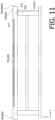
- Fig. 11 is a transverse cross-sectional view of the road surface part 60.
- the road surface part 60 includes the frame 61 and a main body part 60a supported by the frame 61.
- the main body part 60a includes a base 62 and a pavement part 63 held by the base 62.
- On an upper surface of the base 62 a recessed part 621 extending in an extending direction of the road surface part 60 (i.e., in the X axis direction being the travelling direction of the carriage 20) is formed.
- the pavement part 63 is for example formed by filling the recessed part 621 with simulated pavement material which will be described later and hardening the simulated pavement material.
- the road surface 63a with which the test wheel W contacts is formed.
- the main body part 60a is configured from main body part units 600a being road surface units (replaceable structures each including at least a portion of the road surface 63a) and is detachably attached on the frame 61.
- the road surface unit is not limited to a configuration in which the main body part 60a is unitized (hereinafter referred to as a "main body part unit") as in the present embodiment but may be formed to have a configuration in which only the pavement part 63 is unitized (hereinafter referred to as a "pavement part unit”) or a configuration in which the entire road surface part 60 including the frame 61 is unitized (hereinafter referred to as a "road surface part unit").
- the main body part 60a of the present embodiment is configured from a plurality of the may body part unit 600a formed by dividing the main body part 60a in its extending direction and is configured to be replaceable per the main body part unit 600a. It should be noted that the entire main body part 60a may be formed as a single replaceable road surface unit.
- the road surface part 60 By configuring the road surface part 60 from road surface units such as the main body part units 600a as in the present embodiment, it becomes possible to replace at least a part of the road surface 63a.
- the main body part unit 600a at the central part of the road surface part 60 in the extending direction (X axis direction) can be replaced to change a type of the pavement part 63 (e.g., materials, structures, surface profiles and the like) only at the central part.
- the type of the pavement part 63 may be changed for every main body part unit 600a such that, for example, the friction coefficient changes in the extending direction of the road surface part 60.
- the main body part unit 600a is detachably attached on the frame 61 by placing the main body part unit 600a on the frame 61 such that the protruded part 612 and the recessed part 622 fit to each other and by fixing the main body part unit 600a to the frame 61 with (not shown) fixing means such as bolts or cam levers.
- the frame 61 is formed from a plurality of frame units 610 formed by dividing the frame 61 in its extending direction and is replaceable per the frame unit 610.
- the frame unit 610 and the main body part unit 600a are formed in the same length and thus replacement per road surface unit 600 in which the main body part unit 600a is attached to the frame unit 610 is also possible.
- the pavement part 63 is formed integrally with the base 62.
- the pavement part 63 may be configured to be detachable from and attachable to the base 62.
- the pavement part 63 may be configured from a plurality of pavement part units 630 formed by dividing the pavement part 63 in its extending direction, and may be configured to be replaceable per pavement part unit 630.
- the pavement part unit 630 and a base unit 620 may be formed in the same length to make replacement per complex unit in which the pavement part unit 630 is attached to the base unit 620 (in other words, the main body part unit 600a in which the pavement part 63 is made detachable) possible.
- the frame unit 610, the base unit 620 and the pavement part unit 630 may be assembled to form the road surface part unit 600 to make replacement per road surface part unit 600 possible.
- a plurality of road surface part units 600 are connected to form the road surface part 60.
- the plurality of road surface units by configuring the plurality of road surface units to have the same structure, it becomes possible to efficiently manufacture the road surface part 60.
- the track part 10 is divided into a plurality of track part units 100 in its extending direction. It is also possible to extend or shorten the track part 10 by adding or removing the track part unit 100.
- the track part unit 100 is formed in the same length as the road surface part unit 600. Therefore, it is possible to form the track part 10 and the road surface part 60 in the same length.
- the road surface part 60 and the track part 10 may also be configured to be possible to extend, shorten or partially replace per complex unit in which the track part unit 100 and the road surface part unit 600 are integrated.
- a simulated pavement simulating asphalt-paved road i.e., a pavement of which influences on a tire such as wear volume of a tire are comparable with the actual asphalt-paved road
- the simulated pavement is for example formed by shaping and curing simulated pavement material in which binder such as, for example, urethane resin or epoxy resin is added to aggregate formed by crushing (and further polishing and/or etching as necessary) ceramics with excellent wear resistance such as silicon carbide or alumina.
- binder such as, for example, urethane resin or epoxy resin
- ceramics with excellent wear resistance such as silicon carbide or alumina.
- the simulated pavement of the present embodiment has a single-layered structure.
- a simulated pavement in which a plurality of layers formed from different materials are layered in a thickness direction may be used.
- Simulated pavements simulating flagstone pavements, brick pavement, concrete pavement and the like by, for example, adjusting types and/or particle size of the aggregate and/or adjusting types and/or amount of the binder may also be used.
- the road surface 63a may also be formed to cause more (or less) damage on a tire than the actual road surface. It becomes possible to perform accelerated tire deterioration test by using the road surface 63a which has greater influence on a tire than the actual road surface.
- the pavement part 63 may also be formed from actual pavement material (e.g., asphalt compound used for a superficial layer of an asphalt pavement).
- actual pavement material e.g., asphalt compound used for a superficial layer of an asphalt pavement.
- the pavement part 63 replicating or imitating not only a superficial layer of an actual pavement forming the road surface but also a lower layer structure of the actual pavement may also be used.
- the test can be performed in a state where foreign matter (e.g., water, snow, mud water, dirt, sand, gravel, oil or the like or matter simulating the aforementioned foreign matter) which has influence on performance of a tire is scattered on the road surface 63a.
- foreign matter e.g., water, snow, mud water, dirt, sand, gravel, oil or the like or matter simulating the aforementioned foreign matter
- wet braking test can be performed.
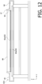
- Fig. 12 is a transverse cross-sectional view of a first variation of the road surface part 60 (a road surface part 60A).
- the road surface part 60A includes a frame part 67attached to the base 62.
- the frame part 67 is bonded to the base 62 to be watertight by caulking or the like and forms a basin 68 together with the base 62.
- Foreign matter e.g., water, gravel, dirt, fallen leaves or the like
- the frame part 67 of this variation is attached on an upper surface of the base 62, but the frame part 67 may be attached on side faces of the base 62.
- the frame part 67 may also be attached on an upper surface of the pavement part 63.
- the road surface part 60A includes a temperature adjusting means 64 configured to be capable of adjusting temperature of the road surface 63a.
- the temperature adjusting means 64 of the present variation has a flow channel 64a embedded in the base 62, a temperature sensor 64b configured to detect temperature of the road surface 63a, and a temperature adjusting device 64c ( Fig. 10 ).
- the temperature sensor 64b is, for example, a contact type temperature sensor which uses a thermocouple, a thermistor or the like or a non-contact type temperature sensor such as an infrared sensor.
- the temperature adjusting device 64c is connected to the control part 72 and adjusts the temperature of the road surface 63a to a set temperature based on a command from the control part 72.
- the temperature adjusting device 64c adjusts temperature of heat carrier (e.g., oil or water containing antifreeze liquid) based on detection result by the temperature sensor 64b and transmits the heat carrier to the flow channel 64a. It is possible to adjust the temperature of the road surface 63a to a predetermined temperature by causing the heat carrier of which temperature is adjusted by the temperature adjusting device to flow through the flow channel 64a.
- An outer surface of the base 62 is coated with heat insulating material 69 to stabilize the temperature of the road surface 63a and to improve heat use efficiency.
- the temperature adjusting means 64 can adjust the temperature of the road surface 63a in a wide range from a low temperature (e.g., -40 degrees Celsius) up to a high temperature (e.g., 80 degrees Celsius). It is possible to form a frozen road surface by filling the basin 68 with water and setting the set temperature of the road surface 63a to below zero. That is, it is possible to perform ice braking test by using the road surface part 60A of the present variation. It is also possible to perform snow braking test in a state where the basin 68 is filled with snow.
- a low temperature e.g., -40 degrees Celsius
- a high temperature e.g. 80 degrees Celsius
- the flow channel 64a is formed to meander at constant intervals within the base 62 in parallel with the road surface 63a.
- the base 62 is segmented into a plurality of sections (the base units 620) in its lengthwise direction and respective flow channels 64a are formed to respective sections. By this configuration, it becomes possible to adjust the temperature of the entire road surface 63a more evenly.
- a load detecting part 65 configured to detect distribution of load the road surface receives from a tire tread of the test wheel W is provided.
- Fig. 13 is a transverse cross-sectional view of the road surface part 60B.
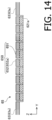
- Figs. 14 and 15 are a transverse cross-sectional view and a plan view of and around the load detecting part 65 of the road surface part 60B, respectively.
- a deep recessed part 621a ( Fig. 14 ) being deeper than the surrounding portion is formed at substantially the center of the bottom in its lengthwise direction (X axis direction) and in its widthwise direction (Y axis direction).
- the deep recessed part 621a is not filled with the pavement part 63 and a plurality of load detecting modules 650 configuring the load detecting part 65 is laid in the deep recessed part 621a.
- the plurality of load detecting modules 650 are disposed at lattice points arranged in the X axis direction and the Y axis direction.
- 150 load detecting modules 650 are arranged at constant intervals (e.g., at 100 mm intervals) in 15 rows in the X axis direction and 10 rows in the Y axis direction, and are fixed to the bottom of the deep recessed part 621a.
- a width of the deep recessed part 621a i.e., a width of the load detecting part 65
- the load detecting module 650 is a module in which a pavement part 652 is attached on an upper surface of a piezoelectric three force components sensor 651.
- the three force components sensor 651 is a cylindrical piezoelectric element whose central axis is oriented in the Z axis direction.
- the pavement part 652 is a cuboidal member whose lengths in the X axis direction and in the Y axis direction are the same.
- the shapes of the three force components sensor 651 and the pavement part 652 may be other shapes.
- the shape of the three force components sensor 651 may be cuboidal and the shape of the pavement part 652 may be cylindrical.
- the shapes of the three force components sensor 651 and the pavement part 652 may be the same.
- An upper surface of the pavement part 652 is arranged perpendicular to the Z axis to form the road surface.
- the pavement part 652 of the present variation is formed from the same material and in the same thickness as the pavement part 63. However, the material and the size of the pavement part 652 may be different from those of the pavement part 63. Also, the pavement part 652 may not be provided to the load detecting module 650 and the upper surface of the load detecting module 650 may be used as the road surface. In this case, a depth of the deep recessed part 621a may be set such that the upper surface of the load detecting module 650 is at the same height as an upper surface of the pavement part 63.
- Various processes are performed based on the load distribution (initial load profile) detected by the load detecting part 65 to generate final load profile data (measured values of the load profile).
- the measurement result of the load profile is displayed on a display device of the control system 1a for example as a three-dimensional CG image to visualize distribution of load acting on the tire tread.
- the load distribution that is detected by the load detecting part 65 (or a load detecting part 165 which will be described later) will be referred to as a detected load distribution (or detected values of the load distribution), and the load distribution that is finally obtained through various processes based on the detected load distribution will be referred to as a measured load distribution (or measured values of the load distribution).
- image data of three profile images respectively representing distributions of the above-described three types of forces f R , fr and fL is generated, and the three profile images are displayed on a screen of the display device simultaneously by arranging the profile images or by sequentially switching the profile images.
- the detection of the load distribution is performed continuously at constant time intervals (e.g., at 5 msec intervals) and simultaneously by all the load detecting modules 650.
- Load measured by each load detecting module 650 is associated with measurement data measured by the six force components sensor 282 of the spindle 280 at the same timing and is stored in a storage device 721 of the control part 72 (or a server 77 connected to the control part 72 via for example a LAN).
- the load detecting part 65 is provided only at the substantially central part of the road surface part 60B in the lengthwise direction and in the widthwise direction.
- the load detecting part 65 may be provided on the whole area of the road surface part 60B.
- the road surface part 60C of the present variation is also provided with the load detecting part 165 configured to detect the distribution of the load the road surface receives from the tire tread of the test wheel W.
- Figs. 16 and 17 are a plan view and a side view of and around the load detecting part 165 of the road surface part 60C, respectively.
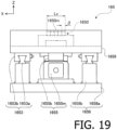
- Figs. 18 , 19 and 20 are a front view, a left side view and a plan view of the load detecting part 165, respectively.
- a recessed part 60p extending in the Y axis direction is formed on an upper surface of the main body part 60a of the road surface part 60C.
- the load detecting part 165 is accommodated inside the recessed part 60p and is fixed to the bottom of the recessed part 60p.
- the load detecting part 165 includes a fixed frame 1658, a movable frame 1659, a pair of linear guides 1653, a sensor array unit 1650, a moving unit 1655, and a sensor position detecting part 1656.
- the linear guides 1653 and rail supporting parts 1658b of the fixed frame 1658 which will be described later are omitted.
- the movable frame 1659 is supported by the pair of linear guides 1653 to be movable in the Y axis direction (i.e., in a widthwise direction of the road surface part 60C).
- the sensor array unit 1650 is attached on an upper surface of the movable frame 1659. Details of the sensor array unit 1650 will be described later.
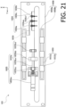
- Fig. 21 is a plan view showing the load detecting part 165 in a state where the movable part (i.e., the movable frame 1659 and the sensor array unit 1650) is removed.
- the fixed frame 1658 includes a substantially rectangular base plate 1658a, and a pair of rail supporting parts 1658b fixed on an upper surface of the base plate 1658a.
- the pair of rail supporting parts 1658b are arranged in the X axis direction with an interval therebetween while orienting their lengthwise directions in the Y axis direction.
- the linear guide 1653 includes a rail 1653a extending in the Y axis direction, and a plurality of (in the present variation, three) carriages 1653b (hereinafter referred to as "runners 1653b") capable of travelling on the rail 1653a.
- the rail 1653a is attached on an upper surface of the rail supporting part 1658b.
- the runners 1653b are attached on a lower surface of the movable frame 1659. The movement of the movable frame 1659 in the Y axis direction is guided by the linear guides 1653.
- the moving unit 1655 is arranged between the pair of rail supporting parts 1658b and the linear guides 1653.
- the moving unit 1655 includes a motor 1655m and a ball screw mechanism 1655b.
- the ball screw mechanism 1655b includes a ball screw 1655ba, a nut 165bb, a bearing part 1655bc, and a bearing part 1655bd.
- the ball screw 1655ba is rotatably supported by a pair of the bearing parts 1655bc and 1655bd at both ends of the ball screw 1655ba.
- One end of the ball screw 1655ba is connected to a shaft of the motor 1655m.
- the nut 1655bb engaging with the wall screw 1655ba is attached on the lower surface of the movable frame 1659.
- the movable frame 1659 and the sensor array unit 1650 moves in the Y axis direction together with the nut 1655bb. That is, a position of the sensor array unit 1650 in the Y axis direction can be changed by rotationally driving the motor 1655m.
- the sensor position detecting part 1656 includes a movable arm 1655a, a plurality of (in the present variation, three) proximity sensors 1656c, and a sensor attaching part 1656b.
- the movable arm 1656a and the sensor attaching part 1656b of the present variation are formed by sheet metal processing but may be formed by other processing methods (e.g., by cutting, casting, injection molding of resin and the like).
- An end of the movable arm 1656a is fixed to the movable frame 1659 and the movable arm 1656a is movable in the Y axis direction together with the movable frame 1659.
- the sensor attaching part 1656b is attached to the fixed frame 1658.
- the plurality of proximity sensors 1656c are attached to the sensor attaching part 1656b.
- the plurality of proximity sensors 1656c are arranged in the Y axis direction while orienting their detecting surfaces 1656cf in the X axis positive direction.
- the plurality of proximity sensors 1656c are arranged in the Y axis direction at constant intervals.
- a proximity part 1656ap adjacent to the proximity sensors 1656c are formed.
- the proximity part 1656ap is formed by bending the tip portion of the movable arm 1656a in a crank shape.
- the proximity part 1656ap is disposed at the same height as the detecting surfaces 1656cf of the plurality of proximity sensors 1656c.
- the detecting surfaces 1656cf of the plurality of proximity sensors 1656c are arranged within a movable range of the proximity part 1656ap in the Y axis direction with intervals therebetween.
- Fig. 22 is an enlarged view of an area E surrounded by a chain double-dashed line in Fig. 18 .
- the sensor array unit 1650 includes a frame 1650a and a plurality of (in the present variation, 150) load detecting modules 1650m.
- a recessed part 1650ap long in the Y axis direction is formed.
- the plurality of load detecting modules 1650m are accommodated in the recessed part 1650ap and are fixed to the bottom of the recessed part 1650ap.
- the plurality of load detecting modules 1650m are arranged in the X axis direction and the Y axis direction at constant intervals (e.g., with substantially no gap therebetween).
- 150 load detecting modules 1650m are arranged in 5 rows in the X axis direction and 30 rows in the Y axis direction.
- the load detecting module 1650m includes a three force components sensor 1651, a pavement part 1652, and a bolt 1653.
- the three force components sensor 1651 and the pavement part 1652 are the same members as the three force components sensor 651 and the pavement part 652 of the second variation, respectively.
- a hole 1651b penetrating in the Z axis direction is formed.
- a bolt hole 1652b extending in the Z axis direction is formed.
- the load detecting module 1650 is integrated and fixed to the frame 1650a by the bolt 1653 inserted through the hole 1651b of the three force components sensor 1651 and screwed in the bot hole 1652b of the pavement part 1652.
- An upper surface of the pavement part 1652 is disposed horizontally to form a road surface 1652a.
- An area in the X axis direction and the Y axis direction where the load detecting modules 1650m are arranged is a detecting area of the sensor array unit 1650.
- the motor 1655m of the moving unit 1655 is connected to the control part 72 via a driver 1655a.
- the three force components sensor 1651 and the proximity sensor 1656c of the sensor position detecting part 1656 are connected to the measuring part 74 via a pre-amplifier 1651a and a pre-amplifier 1656ca, respectively.
- a pre-amplifier 1651a and a pre-amplifier 1656ca are shown.
- Signals from the three force components sensors 1651 and the proximity sensors 1656c are amplified by the pre-amplifiers 1651a and the pre-amplifiers 1656ca, respectively, and are then converted into digital signals at the measuring part 74.
- the sensor array unit 1650 is disposed at a position where the proximity part 1656ap of the movable arm 1656a opposes the detecting surface 1656cf of the proximity sensor 1656c positioned at the center.
- the control part 72 transmits a command for an anti-clockwise rotation to the driver 1655a to move the sensor array unit 1650 in the Y axis direction.
- the driver 1655a which received the command for the anti-clockwise rotation supplies driving current that causes the motor 1655m to rotate in the anti-clockwise direction.
- the ball screw 1655ba rotates in the anti-clockwise direction together with the shaft of the motor 1655m, and the sensor array unit 1650 moves in the Y axis direction together with the nut 1655bb and the movable frame 1659.
- the proximity part 1656ap of the movable part 1656a moves away from the detecting surface 16556cf of the proximity sensor 1656c at the center and the proximity sensor 1656c at the center becomes less responsive to proximation.
- the proximity part 1656ap of the movable arm 1656a reaches a position opposing the detecting surface 1656cf of the proximity sensor 1656c on the left (on the Y axis positive direction side).
- the proximity sensor 1656c on the left detects proximation and outputs a proximation signal indicating detection of proximation.
- the rotations of the shaft of the motor 1655m and the ball screw 1655ba thereby stop and the nut 1655bb and the sensor array unit 1650 also stop, and the displacement of the sensor array unit 1650 completes.
- the moving unit 1655 By providing the moving unit 1655, it becomes possible to shorten a length Ly of the detecting area of the sensor array unit 1650 in the Y axis direction to reduce the number of load detecting modules 1650m necessary to measure the load distribution, and thus it becomes possible to reduce cost necessary to manufacture and maintain the sensor array unit 1650.
- FIG. 23 is a flowchart showing a procedure of the method for obtaining distribution of load acting on the tire tread.
- the control part 72 firstly execute an initializing process S1.
- the carriage 20 in an initial state, the carriage 20 is positioned at an initial position (an initial travelling position) P X0 being set at a position near an end of its movable range in the X axis minus direction.
- the slide frame 44 ( Fig. 4 ) is positioned at an initial position P Z0 being set for example at a position near an upper end of its movable range.
- the test wheel W is lifted off the road surface 63a and it is possible to attach and detach the test wheel W and to adjust alignment of the test wheel W.
- the slip angle and the camber are also adjusted to set values by the slip angle adjusting part 46 and the camber adjusting part 47, respectively.
- the servo motor 32 of the torque applying device 30 is driven and a rotational position ⁇ W of the test wheel W is moved to an initial rotational position ⁇ W0 to complete the initializing process S1.
- a rotational position ⁇ M of the torque applying device 30 is controlled by the belt mechanism 50 and the belt mechanism 23 which use the toothed belts and thus the rotational position ⁇ M depends on a travelling position Px of the carriage 20.
- the torque applying device 30 is always positioned at an initial rotational position ⁇ M0 .
- a number of measurement sets k is reset to 1 (S3), and the test wheel W is made to descend and contact the road surface 63a and a set load is applied to the test wheel W by the load adjusting part 45 (S4).
- the first measurement set S5 is executed.
- the servo motors 141 of respective drive parts 14 are driven, and the carriage 20 travels at a set travelling speed and the test wheel W rotates at a peripheral speed that is substantially the same as the travelling speed of the carriage 20.
- the servo motor 32 of the torque applying device 30 is also driven and a set torque is applied to the test wheel W.
- forces acting on the road surface and the test wheel W are detected by the three force components sensor 1651 of the load detecting part 165 and the six force components sensor 282 of the spindle part 28, respectively, at predetermined time intervals (e.g., at 5 msec intervals).
- the time intervals of the detections by the three force components sensor 1651 and the six force components sensor 282 are appropriately set in accordance with test conditions (e.g., the travelling speed of the carriage 20 and required test accuracy).
- the travelling position Px of the carriage 20 and the rotational position ⁇ W of the test wheel W are calculated at predetermined time intervals.
- the travelling position Px of the carriage 20 is calculated from detection results by the built-in rotary encoders RE ( Fig. 10 ) of the servomotors 141 of the drive parts 14, reduction ratios of the reducers 142 and pitch diameters of the drive pulleys 52 of the belt mechanisms 50.
- the travelling position Px of the carriage 20 is a position of the rotation axis Ay of the test wheel W in the travelling direction of the carriage 20 (in the X axis direction).
- the rotational position ⁇ W of the test wheel W is calculated based on detection results by the rotary encoder 39 of the torque applying device 30 and the built-in rotary encoder RE of the servo motor 32. Specifically, the rotational position ⁇ W of the test wheel W is calculated by adding the product of the rotational position ⁇ M of the shaft 321 of the servo motor 32 detected by the rotary encoder RE of the servo motor 32 (the initial rotational position ⁇ M0 in the initial state being 0 [rad]) and a reduction ratio of the reducer 33 (i.e., a rotational position ⁇ S of the shaft 34) to a rotational position ⁇ H of the housing 31 of the torque applying device 30 detected by the rotary encoder 39.
- a detecting means such as a rotary encoder for detecting a rotational position ⁇ T of an output from the torque applying device 30 (e.g., a rotational position of the spindle 280, the shaft 261 or the shaft 263) may be provided to detect the rotational position ⁇ W of the test wheel W directly with the detecting means.
- the detection results by the three force components sensor 1651 and the six force components sensor 282 are associated with the detection results by the built-in rotary encoders RE of the servo motors 141 of the drive parts 14 (i.e., the travelling position Px of the carriage 20) and the detection result of the rotational position ⁇ W of the test wheel W that are detected at the same timing and are stored in the storage device 721 of the control part 72 (or in a storing means that the control part 72 can access such as the server 77 connected to the control part 72 via for example a LAN).
- the test wheel W is lifted by the load adjusting part 45 to a height at which the test wheel W is lifted off the road surface 63a (e.g., the same height as the initial state) (S6). Then, the drive parts 14 are driven to move the carriage 20 to the initial position P X0 (S7).
- the angular width ⁇ W is, for example, set to a value that is equal to or less than a central angle ⁇ C1 of the test wheel W corresponding to a length Lx ( Fig. 19 ) of the detecting area of the sensor array unit 1650 in the X axis direction (i.e., a rotation angle ⁇ C1 of the test wheel W when the test wheel W rolls for a distance Lx).
- the angular width ⁇ W is set to a value that is the same as or slightly smaller than a central angle ⁇ C2 of the test wheel W corresponding to an arrangement interval ⁇ ( Fig. 19 ) of the load detecting modules 1650m.
- the angular width ⁇ W may for example be set to a value obtained by dividing 2 ⁇ by the preset number n. In this case, the entire circumference of the test wheel W is measured without gap by the n measurement sets.
- Fig. 24 is a flowchart showing a procedure for the load profile calculation S10.
- the load profile calculation S10 is a process for calculating the load profile data based on measurement results obtained by the n measurement sets S5.
- the load profile data is data in which values of three types of forces acting on a tire (i.e., the radial force f R , the tangential force fr and the lateral force f L ) are associated with plane coordinates on the road surface.
- Fig. 25 is a plan view showing positional relationship between the load detecting modules 1650m and the rotation axis Ay of the test wheel W.
- 150 load detecting modules are arranged in 5 rows in the X axis direction and 30 rows in the Y axis direction.
- a number of row of the load detecting module 1650m in the X axis direction will be represented by p
- a number of row of the load detecting module 1650m in the Y axis direction will be represented by q
- a position of the load detecting module650m will be represented by a pair of positive integer [p, q] (hereinafter referred to as an address [p, q]).
- an (x, y) coordinate system is used.
- the (x, y) coordinate system is a two-dimensional orthogonal coordinate system parallel to an (X, Y) coordinate system, the origin of the (x, y) coordinate system being the center of the upper surface of the load detecting module 1650m positioned at the address [3, 1]. That is, the xy plane is a plane on which the road surface of the road surface part 60C is disposed.
- a coordinate whose origin is a fixed point is referred to as an absolute coordinate
- a coordinate whose origin is a movable point is referred to as a relative coordinate.
- the absolute coordinates of respective load detecting modules 1650m are calculated.
- an x coordinate of the rotation axis Ay of the test wheel W (hereinafter referred to as a "coordinate x Ay ") is calculated (S102).
- the coordinates of the rotation axis Ay of the test wheel W are converted from the XY coordinate system into the xy coordinate system.
- relative positions (relative coordinates) of the load detecting modules 1650m with respect to the travelling position Px of the test wheel W (the rotation axis Ay) are calculated (S103).
- Relative coordinates (x r , y r ) of the load detecting modules 1650m are calculated in accordance with the following formulas.
- a load profile relating to the relative position is obtained.
- pieces of load profile data of three types of forces f R , f T and f L are calculated by averaging all the measurement results (i.e., the radial forces f R , the tangential forces fr and the lateral forces f L measured by respective load detecting modules 1650m) for every relative coordinate (x r , y r ) (S104).
- the pieces of load profile data may be calculated as proximate curved surfaces that can be obtained by regression analysis (e.g., curved surface fitting such as the least square method).
- the pieces of load profile data may be calculated while taking into account the rotational position ⁇ W of the test wheel W. That is, the pieces of load profile data may be calculated for each rotational position ⁇ W . In this case, the pieces of load profile data may be calculated while further taking into account symmetric property of a tread pattern of the test tire T about the rotation axis Ay. Specifically, the pieces of load profile data may be calculated for all the rotational positions ⁇ W that are same in phase of a cycle of the tread pattern.
- the number of measurement sets may be increased to perform measurements for a plurality of rotations.
- resolution of the load profile data in the x axis direction is nearly the size of the arrangement interval ⁇ of the load detecting modules 1650m.
- substantial resolution in the x axis direction can be made smaller than the arrangement interval ⁇ of the load detecting modules 1650m. For example, if the measurement sets are repeated while changing the rotational position ⁇ W by 1/m of the central angle ⁇ C2 (m being a natural number), the substantial resolution in the x axis direction can be fined up to nearly ⁇ /m.
- the length Lx of the detecting area of the sensor array unit 1650 in the X axis direction is shorter than a length of the tire tread in the X axis direction. Therefore, the load distribution cannot be obtained for the entire tire tread only by causing the test wheel W to roll over the sensor array unit 1650 once.
- a method of measuring the load distribution on the tire tread in several separate measurements while shifting the rotational position ⁇ W of the test wheel W at the time the test wheel W rolls on the sensor array unit 1650 is adopted.
- this method it becomes possible to shorten the length of the detecting area of the sensor array unit 1650 in the X axis direction and reduce the number of load detecting modules 1650m necessary to measure the load distribution, and thus it becomes possible to reduce costs necessary to manufacture and maintain the sensor array unit 1650.
- a motor capable of controlling position e.g., a servo motor or a step motor
- the substantial resolution in the y axis direction can be fined to nearly 1mm.
- Fig. 26 shows examples of displayed load profiles.
- Fig. 26(a) is a load profile image of the tangential forces f T
- Fig. 26(b) is a load profile image of the lateral forces fr
- Fig. 26(c) is a load profile image of the radial forces f R .
- the load profile images shown in Fig. 26 are images generated by converting values of forces at respective positions (x r , y r ) into brightness.
- the tire testing device 1 includes two belt mechanisms 50. However, the tire testing device 1 may include one belt mechanism 50 or three or more belt mechanisms 50.
- the belt mechanisms 50 are driven by the power generated by the pair of drive parts 14.
- the belt mechanisms 50 may be configured to be driven by one drive part 14 or three or more drive parts 14.
- the toothed belt and the toothed pulleys are used in each of the belt mechanisms 50, 23, 24.
- a flat belt or a V belt may be used in place of the toothed belt in one or more belt mechanisms.
- Other type of winding transmission mechanism such as a chain transmission mechanism or a wire transmission mechanism and other type of power transmission mechanism such as a ball screw mechanism, a gear transmission mechanism or a hydraulic mechanism may be used in place of the belt mechanism.
- the power for driving the carriage 20 and the power for driving the test wheel W are supplied from the common drive parts 14 and are transmitted through the common belt mechanisms 50.
- the present invention is not limited to this configuration.
- the power for driving the carriage 20 and the power for driving the test wheel W may be generated by separate drive parts and may be transmitted through separate power transmission means (e.g., separate belt mechanisms).
- driving of the drive part for driving the carriage and driving of the drive part for driving the test wheel needs to be synchronously controlled in order to synchronize the travelling speed of the carriage 20 and the peripheral speed of the test wheel W.
- simple driving system and control system are realized by commonalizing a portion (the drive parts 14 and the drive belt mechanisms 50) of the mechanism for driving the carriage 20 (a carriage driving means) and a portion (the drive parts 14 and the drive belt mechanisms 50) of the mechanism for driving the test wheel W (a test wheel driving means).
- the commonalization of the carriage driving means and the test wheel driving means (especially the commonalization of the drive parts 14) is made possible due to reduction of load the drive parts 14 bear by the introduction of the torque applying device 30 to isolate a power source for controlling speed of the test wheel W from a power source for controlling torque of the test wheel W.
- the means that makes it possible to change the position of the sensor array unit 1650 in the X axis direction can for example be configured with a motor capable of controlling position and a feed screw mechanism (e.g., a ball screw mechanism) as with the moving unit 1655.
- a feed screw mechanism e.g., a ball screw mechanism
Landscapes
- Physics & Mathematics (AREA)
- General Physics & Mathematics (AREA)
- Engineering & Computer Science (AREA)
- Mechanical Engineering (AREA)
- Tires In General (AREA)
- Testing Of Balance (AREA)
Abstract
Description
- The present invention relates to tire testing devices.
- Since tire performance is influenced by conditions of road surfaces, the tire performance needs to be evaluated for road surfaces of various conditions.
- As tests for evaluating the tire performance, an on-road test in which test tires are for example mounted to wheel rims of a test-dedicated vehicle and the test-dedicated vehicle is made to run on actual roads and an indoor test in which a testing device installed indoor is used are known.
-
Japanese Patent Application Publication No. 2015-72215 Patent Document 1 includes a rotating drum to which a simulated road surface is provided on its outer peripheral surface, and the test is performed by causing a test tire and the drum to rotate in a state where the test tire is made to contact with the simulated road surface. - The indoor test is more accurate and more efficient than the on-road test. However, in the conventional testing device for the indoor test, since the simulated road surface is made to run at high speed during the test, it is difficult to perform the test in road surface conditions in which the road surface is covered with rain, snow, gravel or the like.
- The present invention is made in view of the foregoing circumstance, and the object of the present invention is to provide a tire testing device that is capable of performing the indoor test in various road surface conditions.
- According an embodiment of the present invention, there is provided a tire testing device including a road surface part having a road surface, and a carriage configured to rotatably hold a test wheel provided with a test tire and being capable of travelling along the road surface in a state where the test wheel is made to contact the road surface.
- According to one aspect of the embodiment of the present invention, there is provided a tire testing device including a road surface part having a road surface, and a carriage configured to rotatably hold a test wheel provided with a test tire and being capable of travelling along the road surface in a state where the test wheel is made to contact the road surface, at least a portion of the road surface part being configured from a replaceable road surface unit.
- According to another aspect of the embodiment of the present invention, there is provided a tire testing device including a carriage configured to rotatably hold a test wheel provided with a test tire and being capable of travelling along a road surface in a state where the test wheel is made to contact the road surface, and a driving system configured to drive the test wheel and the carriage. The driving system includes a carriage driving means configured to drive the carriage with respect to the road surface in a predetermined speed, a test wheel driving means configured to drive the test wheel in a rotating speed corresponding to the predetermined speed, a driving means configured to generate power to be used to drive the carriage and the test wheel, and a power distributing means configured to distribute power generated by the driving means to the carriage driving means and the test wheel driving means.
- According to still another aspect of the embodiment of the present invention, there is provided a tire testing device including a carriage configured to rotatably hold a test wheel provided with a test tire and being capable of travelling along a road surface in a state where the test wheel is made to contact the road surface, and a driving system configured to drive the test wheel and the carriage. The driving system includes a driving means configured to generate power to be used to drive the carriage and the test wheel, and a first winding transmission mechanism configured to transmit the power generated by the driving means. The first winding transmission mechanism includes a drive pulley coupled to an output shaft of the driving means, a driven pulley held by the carriage and coupled to the test wheel, and a first winding intermediate node wound around the drive pulley and the driven pulley. The first winding intermediate node has a first portion and a second portion stretched in a travelling direction of the carriage and configured to be driven in directions opposite to each other, passes over the driven pulley at the first portion, and is fixed to the carriage at the second portion.
- According to still another aspect of the embodiment of the present invention, there is provided a tire testing device including a carriage configured to rotatably hold a test wheel provided with a test tire and being capable of travelling on a base along a road surface in a state where the test wheel is made to contact the road surface, and a driving system configured to drive the test wheel and the carriage. The driving system includes a test wheel driving means configured to drive the test wheel. The test wheel driving means includes a rotational motion supplying means configured to supply rotational motion of a rotating speed corresponding to a speed of the carriage, and a torque applying means configured to apply a predetermined torque to the test wheel by changing a phase of the rotational motion supplied from the rotational motion supplying means.
- According to still another aspect of the embodiment of the present invention, there is provided a tire testing device including a carriage configured to rotatably hold a test wheel provided with a test tire and being capable of travelling on a base along a road surface in a state where the test wheel is made to contact the road surface, and a driving system configured to drive the test wheel and the carriage. The driving system includes a test wheel driving means configured to drive the test wheel. The test wheel driving means includes two driving means configured to generate power for rotationally driving the test wheel, and a power coupling means configured to couple power generated by the two driving means. The two driving means includes a first motor mounted on the base, and a second motor mounted on the carriage.
- According to an embodiment of the present invention, it becomes possible to perform the indoor test in various road surface conditions.
-
- [
Fig. 1] Fig. 1 is a front view of a tire testing device according to an embodiment of the present invention. - [
Fig. 2] Fig. 2 is a left side view of the tire testing device according to the embodiment of the present invention. - [
Fig. 3] Fig. 3 is a plan view of the tire testing device according to the embodiment of the present invention. - [
Fig. 4] Fig. 4 is a diagram showing structures of and around a carriage. - [
Fig. 5] Fig. 5 is a diagram showing structures of and around the carriage. - [
Fig. 6] Fig. 6 is a diagram showing structures of and around the carriage. - [
Fig. 7] Fig. 7 is a cross-sectional view of a driven part. - [
Fig. 8] Fig. 8 is a side cross-sectional view of a torque generating device. - [
Fig. 9] Fig. 9 is a diagram showing structures of and around a spindle. - [
Fig. 10] Fig. 10 is a block diagram showing a schematic configuration of a control system. - [
Fig. 11] Fig. 11 is a transverse cross-sectional view of a road surface part. - [
Fig. 12] Fig. 12 is a transverse cross-sectional view of a first variation of the road surface part. - [
Fig. 13] Fig. 13 is a transverse cross-sectional view of a second variation of the road surface part. - [
Fig. 14] Fig. 14 is a transverse cross-sectional view of the second variation of the road surface part around a load detecting part. - [
Fig. 15] Fig. 15 is a plan view of the second variation of the road surface part around a load detecting part. - [
Fig. 16] Fig. 16 is a plan view of a third variation of the road surface part around a load detecting part. - [
Fig. 17] Fig. 17 is a side view of the third variation of the road surface part around the load detecting part. - [
Fig. 18] Fig. 18 is a front view of the third variation of the load detecting part. - [
Fig. 19] Fig. 19 is a side view of the third variation of the load detecting part. - [
Fig. 20] Fig. 20 is a plan view of the third variation of the load detecting part. - [
Fig. 21] Fig. 21 is a plan view of the third variation showing a state where a movable part of the load detecting part is removed. - [
Fig. 22] Fig. 22 is an enlarged view of an area E shown inFig. 18 . - [
Fig. 23] Fig. 23 is a flowchart showing a procedure for obtaining distribution of load acting on a tire tread in the third variation. - [
Fig. 24] Fig. 24 is a flowchart showing a procedure for a load profile calculation in the third variation. - [
Fig. 25] Fig. 25 is a plan view showing arrangement relationship between load detecting modules and a rotation axis of a test wheel in the third variation. - [
Fig. 26] Fig. 26 shows display examples of load profiles in the third variation. - Hereinafter, embodiments of the present invention will be described with reference to the drawings. In the following description, the same or corresponding numerals are assigned to the same or corresponding components, and redundant descriptions are herein omitted.
-
Figs. 1 ,2 and3 are a front view, a left side view and a plan view of atire testing device 1 according to an embodiment of the present invention, respectively.Figs. 4 ,5 and6 are a front view, a left side view and a plan view showing structures of and around acarriage 20 which will be described later, respectively. InFigs. 4 to 6 , for convenience of explanation, some components are omitted or shown in cross-sections. - In
Figs. 2 and5 , a direction from the right to the left is defined as an X axis direction, a direction perpendicular to the paper from the back side to the front side is defined as a Y axis direction, and a direction from the bottom to the top is defined as a Z axis direction. The X axis direction and the Y axis direction are horizontal directions orthogonal to each other, and the Z axis direction is a vertical direction. Also, a front-rear direction, an up-down direction and a left-right direction are defined as directions when facing a travelling direction of a carriage 20 (X axis positive direction). That is, an X axis positive direction is defined as front, an X axis negative direction is defined as rear, a Y axis positive direction is defined as left, a Y axis negative direction is defined as right, a Z axis positive direction is defined as up, and a Z axis negative direction is defined as down. - The
tire testing device 1 includes atrack part 10 and aroad surface part 60 elongated in the X axis direction, and acarriage 20 that is capable of travelling on thetrack part 10 in the X axis direction. As shown inFig. 3 , to a left portion of thetrack part 10, an elongated space Sp1 extending over substantially the entire length of thetrack part 10 in the X axis direction is provided. Theroad surface part 60 is accommodated in this space Sp1. On an upper surface of theroad surface part 60, aroad surface 63a (a paved part 63) with which a test tire T mounted to thecarriage 20 contacts is provided. In the present embodiment, in order to make it possible to replace theroad surface part 60 in accordance with test conditions, thetrack part 10 and theroad surface part 60 are separated from each other. It should be noted that a base frame 11 (hereinafter abbreviated to a "base 11") of thetrack part 10 and aframe 61 of theroad surface part 60 may be integrally formed. - To the
carriage 20, a test wheel W (a wheel rim Wr to which the test tire T is mounted) is attached. When performing the test, thecarriage 20 travels in a state where the test wheel W is in contact with theroad surface 63a, and the test tire T rolls on theroad surface 63a. - The
track part 10 includes a plurality of (in the present embodiment, three) linear guideways (hereinafter abbreviated to "linear guides") 13 configured to guide movement of thecarriage 20 in the X axis direction, and one or more drive parts 14 configured to generate mechanical power for driving thecarriage 20. In the present embodiment, two pairs of the drive parts 14 (a pair of drive parts 14LA and 14LB on the left and a pair of drive parts 14RA and 14RB on the right) are mounted on thebase 11 of thetrack part 10 near four corners of thebase 11. The drive parts 14LA and 14RA are arranged at a rear end portion of thetrack part 10, and the drive parts 14LB and 14RB are arranged at a front end portion of thetrack part 10. - As shown in
Fig. 6 , each drive part 14 includes aservo motor 141, and anoptional reducer 142 configured to reduce rotating speed of output from theservo motor 141. The drive parts 14RA and 14RB on the right serve both as a carriage driving means for driving thecarriage 20 to travel and as a rotational motion supplying means for supplying, to the test wheel W, rotational motion of rotating speed corresponding to a travelling speed of the carriage. The drive parts 14LA and 14LB on the left serve as carriage driving means. - In the present embodiment, as the
servomotor 141, a super-low inertia and high-power type AC servo motor with an inertia moment of a rotating part being equal to or less than 0.01 kg•m2 (preferably equal to or less than 0.008 kg•m2) and with a rated power of 3 to 60 kW (7 to 37 kW being more suitable for practical use) is used. - The
tire testing device 1 includes a pair of belt mechanisms 50 (50L, 50R) on each of the left side and the right side. Thebelt mechanisms 50 transmit power generated by the drive parts 14 to thecarriage 20 and drives thecarriage 20 in the X axis direction. Eachbelt mechanism 50 includes atoothed belt 51, a pair of drive pulleys 52 (52A, 52B), and three driven pulleys 53 (53A, 53B, 53C). The drive pulleys 52 and the driven pulleys 53 are toothed pulleys that engage with thetoothed belt 51. - The
toothed belt 51 has core wires made of steel wires. It should be noted that a toothed belt having core wires made of so-called super fiber such as carbon fiber, aramid fiber or ultra-high molecular weight polyethylene fiber may be used as thetoothed belt 51. By the use of light-weight and high-strength core wires such as carbon core wires, it becomes possible to drive thecarriage 20 at high acceleration (or to apply high driving/braking force to the test wheel W) using a motor of relatively low output power, and thus it becomes possible to downsize the tire testing device 1 (or to make capacity of thetire testing device 1 large). - The
belt mechanism 50R on the right serves both as a carriage driving means for driving thecarriage 20 to travel and as a primary power transmitting part for transmitting power supplied from the rotational motion supplying means (drive parts 14RA, 14RB) to a secondary power transmitting part which will be described later. Thebelt mechanism 50L on the left serves as a carriage driving means. - In the following description, as for components that are provided as a pair on the left side and on the right side, as a general rule, the one on the left side will be described, and the one on the right side will be written together in bracket to omit redundant description.
- The
toothed belt 51 of thebelt mechanism 50L [50R] on the left [right] is wound around the pair of drive pulleys 52 (52A, 52B) and the three driven pulleys 53 (53A, 53B, 53C). The pair of drive pulleys 52A, 52B are respectively coupled to output shafts of the pair of drive parts 14LA, 14LB [14RA, 14RB] on the left [right]. The three drivenpulleys part 22L [22R] on the left [right] which will be described later. - As shown in
Fig. 5 , both ends of eachtoothed belt 51 are fixed to amain frame 21 of thecarriage 20 with respective belt clamps 54 (54A, 54B), thereby eachtoothed belt 51 forming a loop via thecarriage 20. The pair of drive pulleys 52A, 52B (Fig. 2 ) of thebelt mechanism 50 are fixed pulleys that are arranged across an area through which thecarriage 20 can travel and that are held on the base 11 (i.e., pulleys whose respective centers of gravity are fixed with respect to the base 11). The driven pulleys 53 (Fig. 5 ) are moving pulleys that are held on thecarriage 20 and can move together with thecarriage 20. - In the present embodiment, the pair of drive parts 14LA, 14LB [14RA, 14RB] are driven in the same phase. Effective diameters (i.e., pitch circle diameters) or numbers of teeth of the drive pulleys 52 and the driven pulleys 53 are the same. The drive parts 14LA, 14LB on the left and the drive parts 14RA, 14RB on the right are mounted with the left side and the right side reversed and are driven in opposite phases. As the toothed belt 51L [51R] is driven by the drive parts 14LA, 14LB [14RA, 14RB], the
carriage 20 is pulled by the toothed belt 51L [51R] and is driven in the X axis direction. - The
track part 10 includes a plurality of (in the present embodiment, three) linear guides 13 (13A, 13B, 13C). Each linear guide 13 includes arail 131 extending in the X axis direction and forming a track, and one or more (in the present embodiment, thee) carriages (hereinafter referred to as "runners 132") that can travel on therail 131. Eachrail 131 is laid on an upper surface of thebase 11 of thetrack part 10. Therails 131 of the twolinear guides rail 131 of the remaininglinear guide 13C is arranged along a right end of thebase 11, and the threerails 131 are attached to thebase 11. Eachrunner 132 is attached on a lower surface of thecarriage 20. - As shown in
Fig. 6 , thecarriage 20 includes themain frame 21, drivenparts belt mechanisms Fig. 4 ) configured to rotatably hold the test wheel W to which the test tire T is mounted, analignment part 40 configured to be capable of adjusting alignment of the test wheel W with respect to theroad surface 63a and load on theroad surface 63a, and aspindle driving mechanism 20D configured to rotationally drive aspindle 280 of thespindle part 28. Thespindle 280 is an axle to which the test wheel W is to be mounted. -
Fig. 7 is a cross-sectional view showing an outline of a structure of the drivenpart 22R on the right. The drivenpart 22R includes aframe 221, three sets ofbearings 222, and threeshafts 223A-C. Three through holes extending in the Y axis direction are formed to theframe 221, and each of theshafts 223A-C is rotatably supported by a set of thebearings 222 fitted in respective through holes. In the present embodiment, each of theshafts 223A-C is supported by a pair of thebearings 222, but each of theshafts 223A-C may be supported by onebearing 222 or three ormore bearings 222. To end portions of theshafts 223A-C protruding from one face of theframe 221, drivenpulleys 53A-C of thebelt mechanism 50R are respectively attached. - In the driven
part 22R on the right, only theshaft 223B at the center in the X axis direction is longer than the other two (theshafts shaft 223B is protruding from the other face of theframe 221. To the other end portion of theshaft 223B, adrive pulley 231 of abelt mechanism 23 which will be described later is attached. That is, thebelt mechanism 50R on the right and thebelt mechanism 23 are coupled via theshaft 223B. - The driven
part 22L on the left has a configuration similar to the above-describeddriven part 22R on the right, but differs from the drivenpart 22R on the right in that the drivenpart 22L is arranged with the left side and the right side reversed and in that all the threeshafts 223A-C are short and the drivenpulley 231 is not attached to the other end portion of theshaft 223B. - As shown in
Fig. 6 , thespindle driving mechanism 20D includes thebelt mechanism 23, atorque applying device 30, abelt mechanism 24, and a slide type constant velocity joint 25. Power transmitted from thebelt mechanism 50R on the right to thebelt mechanism 23 through theshaft 223B (Fig. 7 ) of the drivenpart 22R on the right is transmitted to the spindle part 28 (Fig. 4 ) through thetorque applying device 30, thebelt mechanism 24 and the slide type constant velocity joint 25, and rotationally drives the test wheel W mounted to thespindle part 28. That is, a portion of the power generated by the drive parts 14RA, 14RB on the right is used to drive thecarriage 20, and the other portion of the power is used to rotationally drive the test wheel W. That is, thebelt mechanism 50R on the right serves as a means for driving the carriage 20 (the carriage driving means), as a means for driving the test wheel W (a test wheel driving means), and as a means for distributing the power generated by the drive parts 14RA, 14RB to the power for driving thecarriage 20 and to the power for driving the test wheel W (a power distributing means). - An
upper portion 51a and alower portion 51b of thetoothed belt 51 of thebelt mechanism 50 are stretched in the travelling direction of thecarriage 20 and are driven in directions opposite to each other. Specifically, thelower portion 51b of thetoothed belt 51 which is fixed to thecarriage 20 is driven in the travelling direction of the carriage along with thecarriage 20, and theupper portion 51a is driven in a direction opposite to the travelling direction of thecarriage 20 and thelower portion 51b. Theupper portion 51a of thetoothed belt 51 configured to travel in the direction opposite to the travelling direction of thecarriage 20 is wound around the driven pulleys 53 attached to thecarriage 20, and the driven pulleys 53 are driven by theupper portion 51a. The power applied to the drivenpulley 53B is transmitted to the test wheel W through the secondary power transmitting part consisting of thebelt mechanism 23, thetorque applying device 30, thebelt mechanism 24, the slide type constant velocity joint 25 and thespindle part 28, and is used to drive the test wheel W. By such configuration of thebelt mechanism 50, it is made possible to drive both thecarriage 20 and the test wheel W with thetoothed belt 51. - In the present embodiment, the configuration in which the
carriage 20 and the test wheel W are driven by using rotational motion that is transmitted by a common power transmitting device (i.e., thebelt mechanism 50R) is adopted. By this configuration, it is made possible to rotationally drive the test wheel W in a peripheral speed (a rotating speed) corresponding to a travelling speed of thecarriage 20 at all times regardless of the travelling speed of thecarriage 20. Also, in order to reduce working amount (i.e., power consumption) of thetorque applying device 30, the present embodiment is configured such that the test wheel W is rotationally driven in the peripheral speed that is substantially the same as the travelling speed of thecarriage 20 when thetorque applying device 30 is not active. -
Fig. 8 is a side cross-sectional view of thetorque applying device 30. Thetorque applying device 30 generates torque to be applied to the test wheel W and outputs the torque by superposing on the rotational motion transmitted by thebelt mechanism 23. In other words, thetorque applying device 30 can apply the torque to the test wheel W (i.e., thetorque applying device 30 can apply driving force or braking force between theroad surface 63a and the test wheel W) by changing phase of the rotational motion transmitted by thebelt mechanism 23. - By incorporating the
torque applying device 30 in thespindle driving mechanism 20D, it becomes possible to divide roles between a power source (the drive parts 14RA, 14RB) for controlling the rotating speed and a power source (aservo motor 32 which will be described later) for controlling the torque. Due to this configuration, it becomes possible to use a power source of a smaller capacity and to control the rotating speed and the torque to be applied to the test wheel W with higher accuracy. Also, since torque that acts on thebelt mechanism 50L decreases by incorporating thetorque applying device 30 in thecarriage 20, it becomes possible to downsize thebelt mechanism 50L (e.g., decrease a number of toothed belts used) and to use members of lower load capacities. - The
torque applying device 30 includes ahousing 31; aservo motor 32, areducer 33 and ashaft 34 that are mounted inside thehousing 31; two bearingparts housing 31; aslip ring part 37; acolumnar support 38 configured to support theslip ring part 37; and arotary encoder 39. A rotating speed of thehousing 31 is detected by therotary encoder 39. - In the present embodiment, as the
servo motor 32, a super-low inertia and high-power type AC servo motor with an inertia moment of a rotating part being equal to or less than 0.01 kg•m2 and with a rated power of 7 to 37 kW is used. - The
housing 31 has amotor accommodating part 311 and acap part 312 being substantially cylindrical and of large diameters, and a pair ofshaft parts motor accommodating part 311. To an end (a left end inFig. 8 ) of themotor accommodating part 311, theshaft part 313 is coaxially coupled (i.e., coupled in a manner such that themotor accommodating part 311 and theshaft part 313 share a center line). To the other end (a right end inFig. 8 ) of themotor accommodating part 311, theshaft part 314 is coaxially coupled via thecap part 312. Theshaft part 313 is rotatably supported by the bearingpart 36, and theshaft part 314 is rotatably supported by the bearingpart 35. - A
flange 314a is formed at a tip of theshaft part 314, and a drivenpulley 232 of thebelt mechanism 23 is coaxially coupled to theflange 314a. Atoothed belt 233 of thebelt mechanism 23 is wound around the drivenpulley 232 and the drive pulley 231 (Fig. 7 ). Thehousing 31 is rotationally driven by thebelt mechanism 23. - A
bearing 315 is provided on an inner periphery of theshaft part 314. Theshaft 34 is inserted in a hollow portion of theshaft part 314 and is rotatably supported by thebearing 315. Theshaft 34 penetrates through theshaft part 314 and the drivenpulley 232 and an end portion of theshaft 34 protrudes to the inside of thecap part 312. Adrive pulley 241 of thebelt mechanism 24 is coaxially coupled to the other end portion of theshaft 34 which penetrated through ahole 232a of the drivenpulley 232. Atoothed belt 243 is wound around thedrive pulley 241. - The
servo motor 32 is accommodated in a hollow portion of themotor accommodating part 311. Ashaft 321 of theservo motor 32 is arranged coaxially with themotor accommodating part 311, and a motor case 320 (i.e., a stator) of theservo motor 32 is fixed to themotor accommodating part 311 with a plurality ofstud bolts 323. Aflange 322 of theservo motor 32 is coupled to agear case 331 of thereducer 33 via acoupling tube 324. Thegear case 331 of thereducer 33 is fixed to aninner flange 312a of thecap part 312. - The
shaft 321 of theservo motor 32 is connected to aninput shaft 332 of thereducer 33. Theshaft 34 is connected to anoutput shaft 333 of thereducer 33. Torque that is output by theservo motor 32 is amplified by thereducer 33 and is transmitted to theshaft 34. Rotation output from theshaft 34 to thebelt mechanism 24 is a superposition of the rotation of thehousing 31 driven by thebelt mechanism 23 and the torque generated by theservo motor 32 and thereducer 33. That is, theshaft part 314 of thehousing 31 is an input shaft of thetorque applying device 30, and theshaft 34 is an output shaft of thetorque applying device 30. Thetorque applying device 30 outputs the torque generated by thetorque applying device 30 through the output shaft by superposing the torque on the rotational motion transmitted to the input shaft. - The
slip ring part 37 includes a plurality of pairs of aslip ring 37a and abrush 37b, a supportingframe 37c and acoupling tube 37d. The plurality ofslip rings 37a are arranged apart from each other and are fitted on an outer periphery of thecoupling tube 37d. - The
coupling tube 37d is coaxially coupled to theshaft part 313 of thehousing 31. Thebrushes 37b contacting outer peripheries of thecorresponding slip rings 37a are supported by the supportingframe 37c attached to thecolumnar support 38. Acable 325 of theservo motor 32 passes through the hollow portion of theshaft part 313 and is connected to theslip rings 37a. Thebrushes 37b are connected to aservo amplifier 32a (Fig. 10 ). That is, theservo motor 32 and theservo amplifier 32a are connected to each other via theslip ring part 37. - As shown in
Figs. 4 and6 , the drivenpulley 242 around which thetoothed belt 243 of thebelt mechanism 24 is wound is coaxially coupled to an end of ashaft 261 rotatably supported by the bearingpart 262. The other end of theshaft 261 is connected to an end of the slide type constant velocity joint 25. The other end of the slide type constant velocity joint 25 is coupled to thespindle 280 via ashaft 263 and the like. The slide type constant velocity joint 25 is configured to be capable of transmitting rotation smoothly without rotation fluctuation regardless of an operating angle (an angle between the input shaft and the output shaft). The slide type constant velocity joint 25 is variable in length. - The
spindle 280 is supported by thealignment part 40 such that its angle and position of the input shaft is variable. By coupling thespindle 280 and theshaft 261 held by the bearingpart 262 via the slide type constant velocity joint 25, even if the angle and/or position of thespindle 280 change, the slide type constant velocity joint 25 flexibly conforms to the change. Therefore, large strain does not occur to thespindle 280 and theshafts spindle 280 without change in speed. - As shown in
Fig. 5 , thealignment part 40 includes a pair of pivotingframes 41, a pair of curved guideways 42 (hereinafter abbreviated to "curved guides"), aslide frame 44, and two pairs of linear guides 43. - Each pivoting
frame 41 is placed on themain frame 21 of thecarriage 20 via thecurved guide 42. Thecurved guide 42 includes an arc-like rail 421 attached on an upper surface of themain frame 21, and a plurality of (in the present embodiment, two) carriages 422 (hereinafter referred to as "runners 422") that can travel on therail 421. Therunners 422 are attached on a bottom surface of the pivotingframe 41. The pair ofcurved guides 42 and the pair of pivotingframes 41 are respectively arranged to oppose to each other in the front-rear direction across a vertical line V passing through a center C of the test wheel W. A center of curvature of eachcurved guide 42 is on the vertical line V. That is, each pivotingframe 41 is supported by thecurved guide 42 to be pivotable about the vertical line V. - As shown in
Fig. 4 , theslide frame 44 has acolumn part 441, acoupling part 442, and afork 443 in this order from the top. The column part 441 (i.e., an upper portion of the slide frame 44) is arranged vertically such that the center line thereof coincides with the vertical line V. The fork 443 (i.e., a lower portion of the slide frame 44) is set back rightward (in a direction of a rotation axis Ay) with respect to the vertical line V so as not to contact with the test wheel W. Thecoupling part 442 extends in the Y axis direction and couples a lower end portion of thecolumn part 441 and an upper end portion of thefork 443 together. Therefore, theslide frame 44 is formed in a substantially crank shape when viewed in the X axis direction. - As shown in
Fig. 5 , a lower portion of thefork 443 is branched in the front-rear direction. To lower end portions of thefork 443 branched into two,respective bearings 443a are provided to be coaxial with respect to each other. -
Fig. 9 is a diagram showing structures of and around thespindle part 28. Thespindle part 28 is arranged between a pair of thebearings 443a (Fig. 5 ) provided to the lower end portions of thefork 443 while orienting a central axis (the rotation axis Ay) of thespindle 280 in the left-right direction. Thespindle part 28 is supported by the pair ofbearings 443a to be rotatable about a rotation axis Cx extending in the front-rear direction. The directions of the rotation axis Ay of thespindle 280 and the rotation axis Cx of aspindle case 284 change in accordance with the alignment of thespindle 280 and thus do not necessarily coincide with the Y axis direction and the X axis direction, respectively. - The
spindle part 28 includes thespindle 280, and thespindle case 284 configured to rotatably support thespindle 280. Thespindle 280 includes abody part 281, a sixforce components sensor 282, and ahub 283. Thebody part 281 is a cylindrical shaft. The sixforce components sensor 282 is a substantially cylindrical member that is coaxially attached to a tip of thebody part 281 and is a piezoelectric force sensor that is capable of detecting six force components (forces in the three axial directions orthogonal to each other and torques around respective axes). Thehub 283 is a member for attaching the test wheel W and is coaxially attached to a tip of the sixforce components sensor 282. Thebody part 281, the sixforce components sensor 282 and thehub 283 are coupled integrally to form thespindle 280. Thespindle 280 is an axle to which the test wheel W is to be mounted and that rotates integrally with the test wheel W. Since the test wheel W is integrally attached to the sixforce components sensor 282 via thehub 283, six force components acting on the test wheel W are detected by the sixforce components sensor 282. - The
spindle case 284 is a substantially cylindrical member configured to accommodate and rotatably hold thespindle 280. On an inner periphery of thespindle case 284, abearing 285 and a pair ofbearings 286 are attached. Thespindle 280 is rotatably supported by thebearing 285 and thebearings 286. - On side faces of the
spindle case 284 on the front and the rear, a pair ofpivots 287 which respectively rotatably fit to the pair ofbearings 443a (Fig. 5 ) of thefork 443 are attached. That is, thespindle part 28 is supported by the pair ofbearings 443a to be rotatable about the rotation axis Cx. - As shown in
Fig. 4 , thealignment part 40 includes aload adjusting part 45, a slipangle adjusting part 46, and acamber adjusting part 47. Theload adjusting part 45 is a unit configured to adjust load acting on the test wheel. The slipangle adjusting part 46 is a unit configured to adjust a slip angle of the test wheel W by causing the alignment part 40 (more specifically, the pivoting frame 41) to rotate about the vertical line V. Thecamber adjusting part 47 is a unit configured to adjust a camber angle of the test wheel W by causing thespindle part 28 to rotate about the rotation axis Cx (Fig. 9 ). - The
load adjusting part 45 includes aservo motor 451, amotion converter 452, and abracket 453. The above-describedlinear guide 43 may also be included in theload adjusting part 45. Theservo motor 451 is attached to themain frame 21 of thecarriage 20. Themotion converter 452 is a device configured to convert rotational motion of theservo motor 451 into vertical linear motion of a vertically erectedmovable element 452a. As themotion converter 452, for example, a rack-and-pinion mechanism, a mechanism in which an intersecting shaft such as a bevel gear and a feed screw are combined, or a mechanism in which a skewed shaft such as a worm gear or a screw gear and a feed screw are combined is used. Thebracket 453 is arranged right below themovable element 452a of themotion converter 452, and is attached to a side face of thecolumn part 441 of theslide frame 44 while facing aflange 453a up. - As the
movable element 452a of themotion converter 452 is caused to descend by driving theservo motor 451, a lower end of themovable element 452a abuts theflange 453a of thebracket 453. As theservo motor 451 is further driven, theslide frame 44 is pressed vertically downward by themovable element 452a via thebracket 453. The test wheel W held by thealignment part 40 is thereby pressed against theroad surface 63a, and load depending on a height (i.e., a position in the Z axis direction) of themovable element 452a acts between the test tire T and theroad surface 63a. The load that acts on the test wheel W is detected by the six force components sensor 282 (Fig. 8 ) of thespindle part 28. The driving of theservo motor 451 is controlled such that the detected load coincides with a set load value. - As shown in
Fig. 6 , a portion of theload adjusting part 45 is arranged in a space Sp2 surrounded by the pair of pivotingframes 41 and thecolumn part 441 of theslide frame 44. By this configuration, space is efficiently used and downsizing of the carriage is realized. - The slip
angle adjusting part 46 includes aservo motor 461 attached to themain frame 21 of thecarriage 20, areducer 462, adrive gear 463 coupled to an output shaft of thereducer 462, and a drivengear 464 that engages with thedrive gear 463. As thedrive gear 463, for example, a spur gear or a sector gear is used. The drivengear 464 is a sector gear. As the gear mechanism (thedrive gear 463 and the driven gear 464) of the slipangle adjusting part 46, a worm gear, a bevel gear, a screw gear and the like may be used. Theservo motor 461, thereducer 462 and thedrive gear 463 are attached to themain frame 21 of thecarriage 20. The drivengear 464 is attached to the side face of thecolumn part 441 of theslide frame 44 such that a rotation axis of the drivengear 464 coincides with the vertical line V. - Rotation of the
servo motor 461 is reduced by thereducer 462 and is transmitted to the drivengear 464 via thedrive gear 463. The drivengear 464 and theslide frame 44 thereby rotates about the vertical line V. As a result, the test wheel W supported by theslide frame 44 via thespindle part 28 also rotates about the vertical line V and the slip angle of the test wheel W changes. - As shown in
Fig. 6 , a portion of the slipangle adjusting part 46 is arranged in a space Sp3 surrounded by the pair of pivotingframes 41 and thecolumn part 441 of theslide frame 44. By this configuration, space is efficiently used and downsizing of the carriage is realized. The space Sp2 in which theload adjusting part 45 is arranged and the space Sp3 in which the slipangle adjusting part 46 is arranged are spaces that are provided on opposite sides of thecolumn part 441 in the left-right direction. By providing theload adjusting part 45 and the slipangle adjusting part 46 in different spaces, assembly and maintenance efficiencies improve. - As shown in
Fig. 9 , thecamber adjusting part 47 includes anupper arm 471 attached to a right end of thecoupling part 442, a joint 472 rotatably supported by theupper arm 471, a full thread bolt 475 (hereinafter referred to as a "stud 475") to which the joint 472 is attached, arod end 476 attached to one end of thestud 475, and alower arm 478 rotatably coupled to therod end 476 with apin 477. An end portion of thelower arm 478 is fixed to thespindle case 284. It should be noted that theupper arm 471 may be attached to thefork 443 of theslide frame 44. - The
upper arm 471 is a flat plate extending in parallel with the rotation axis Ay (i.e., in a direction away from the vertical line V), and is arranged perpendicular to the rotation axis Cx of thespindle case 284. To a tip portion of theupper arm 471, apivot 471a parallel to the rotation axis Cx is provided. - The joint 472 is a substantially cuboidal member to which a through hole for inserting the
stud 475 is formed. To the joint 472, abearing 473 that rotatably fits to thepivot 471a of theupper arm 471 is provided. That is, the joint 472 is supported to be rotatable about thepivot 471a parallel to the rotation axis Cx of thespindle case 284. The joint 472 is nipped between a pair ofnuts 474 fitted to thestud 475 and is fixed to thestud 475. - A tip portion of the
lower arm 478 is coupled to a lower end portion of therod end 476 by thepin 477. Thepin 477 that couples therod end 476 and thelower arm 478 together is a pivot parallel to the rotation axis Cx of thespindle case 284 too. That is, theslide frame 44 and upper arm 471 (a first link), thestud 475 and rod end 476 (a second link), and thelower arm 478 and spindle case 284 (a third link) are circularly coupled together via three pivots parallel to the rotation axis Cx [thepivot 471a (a first joint), the pin 477 (a second joint) and the pivot 287 (a third joint)] to be rotatable about respective pivots, thereby forming a link mechanism. - A length of a variable-
length link 47L connecting the two joints (thepivot 471a and the pin 477) changes as positions of thenuts 474 along thestud 475 change. At this time, thelower arm 478 and thespindle case 284 rotates about the pivot 287 (the rotation axis Cx) and inclination of the rotation axis Ay of thespindle 280 and the test wheel W with respect to theroad surface 63a changes. Therefore, it is possible to adjust the camber by elongating and contracting the variable-length link 47L by changing the positions of thenuts 474 along thestud 475. The camber changes toward the minus side when the variable-length link 47L is elongated and changes toward the plus side when the variable-length link 47L is contracted. - The
tire testing device 1 includes a braking system 27 (hereinafter abbreviated to a "brake 27") that can decelerate the rotation of thespindle 280. Thebrake 27 includes adisc rotor 271 attached to thespindle 280, acaliper 272 attached to thelower arm 478, and a hydraulic pressure supplying device 276 (Fig. 10 ) configured to supply hydraulic pressure to thecaliper 272. - The
spindle 280 is coupled to the slide type constant velocity joint 25 of thespindle driving mechanism 20D (Fig. 6 ) via anattachment 273, thedisc rotor 271 and theshaft 263. - The
lower arm 478 is formed in a crank shape whose middle portion is set back upward (i.e., in a direction away from the spindle 280). Thecaliper 272 of thebrake 27 is attached to the middle portion of thelower arm 478 being away from thespindle 280 via anattachment 275. - The
attachment 273 and theshaft 263 are replaceable small members that are manufactured in accordance with a shape of thedisc rotor 271. Theattachment 275 is a relatively easily replaceable and low-cost small part that is manufactured in accordance with a shape of thecaliper 272. By using theattachments shaft 263, it becomes possible to change types of thebrake 27 at lower cost since it becomes unnecessary to replace thespindle 280 and/or the slide type constant velocity joint 25 whose replacing costs are relatively high when changing the types of the brake 27 (thedisc rotor 271 and the caliper 272). -
Fig. 10 is a block diagram showing a schematic configuration of acontrol system 1a of thetire testing device 1. Thecontrol system 1a includes acontrol part 72 configured to control operation of the entire device, a measuringpart 74 configured to perform various measurements, and aninterface part 76 configured for input from and output to outside. - To the
control part 72, theservomotors 141 of respective drive parts 14, theservo motor 32 of thetorque applying device 30, theservo motor 451 of theload adjusting part 45 and theservo motor 461 of the slipangle adjusting part 46 are connected viaservo amplifiers - Also, to the
control part 72, the hydraulicpressure supplying device 276 of thebrake 27 is connected. The hydraulicpressure supplying device 276 generates a predetermined hydraulic pressure based on a command from thecontrol part 72 and supplies the hydraulic pressure to thecaliper 272. The hydraulicpressure supplying device 276 includes aservo motor 276b, amotion converter 276c configured to convert rotational motion output by theservo motor 276b into linear motion, abrake master cylinder 276d configured to be driven by the linear motion output by themotion converter 276c, and aservo amplifier 276a configured to generate driving current to be supplied to theservo motor 276b based on a command from thecontrol part 72. - The
control part 72 andrespective servo amplifiers control part 72 and respective servo amplifiers. It is thereby made possible to perform synchronized control with high precision (with high resolution and high accuracy in the time axis). - To the measuring
part 74, the sixforce components sensor 282 is connected via apre-amplifier 282a. Signals from the sixforce components sensor 282 are amplified at thepre-amplifier 282a and are converted into digital signals at the measuringpart 74 to generate measurement data. The measurement data is input to thecontrol part 72. Pieces of phase information detected by built-in rotary encoders RE ofrespective servomotors control part 72 viarespective servo amplifiers - The
interface part 76 includes, for example, one or more of a user interface for input by and output to a user, a network interface for connection to various types of network such as a LAN (Local Area Network), and various types of communication interfaces such as a USB (Universal Serial Bus) and a GPIB (General Purpose Interface Bus) for connection to external devices. The user interface includes, for example, one or more of various types of operation switches, indicators, various types of display devices such as an LCD (Liquid Crystal Display), various types of pointing devices such as a mouse and a touch panel, and various types of input/output devices such as a touch screen, a video camera, a printer, a scanner, a buzzer, a speaker, a microphone and a memory card reader/writer. - The
control part 72 can cause thecarriage 20 to travel in a predetermined speed by synchronously controlling driving of theservo motors 141 of respective drive parts 14 based on speed data that is input through theinterface part 76. In the present embodiment, all the four drive parts 14 are driven in the same phase (To be exact, the drive parts 14LA, 14LB on the left and the drive parts 14RA, 14RB on the right are driven in opposite phases [in opposite rotating directions].). - The
control part 72 can apply a predetermined longitudinal force to the test tire T by controlling driving of theservo motor 32 of thetorque applying device 30 based on data of the longitudinal force (braking force or driving force) to be applied to the test tire T obtained through theinterface part 76. Thecontrol part 72 can also apply a predetermined torque to the test wheel W by controlling thetorque applying device 30 based on torque data (or acceleration data) in place of the longitudinal force data. - The
control part 72 can execute the control of the drive part 14 for causing thecarriage 20 to travel in a predetermined travelling speed (and, at the same time, causing the test tire T to rotate in a peripheral speed that is substantially the same as the travelling speed) and the control of thetorque applying device 30 for applying the longitudinal force (or the torque) to the test tire T synchronously based on a synchronizing signal. - Aside from basic waveforms such as sine wave, half sine wave, sawtooth wave, triangle wave and trapezoid wave, longitudinal force (or torque) waveforms that are measured in on-road tests, longitudinal force (or torque) waveforms that are obtained through simulated calculations, or other arbitrary synthesized waveforms (e.g., waveforms that are generated by a function generator or the like) can be used as waveforms of the torque to be generated by the
torque applying device 30. - Similarly, with regard to the control of the travelling speed of the carriage 20 (or the rotating speed of the test wheel W), aside from the basic waveforms, waveforms of rotating speeds of wheels that are measured in on-road tests, waveforms of change of speed that are obtained through simulated calculations, or other arbitrary synthesized waveforms (e.g., waveforms that are generated by a function generator or the like) can be used.
-
Fig. 11 is a transverse cross-sectional view of theroad surface part 60. Theroad surface part 60 includes theframe 61 and amain body part 60a supported by theframe 61. Themain body part 60a includes abase 62 and apavement part 63 held by thebase 62. On an upper surface of thebase 62, a recessedpart 621 extending in an extending direction of the road surface part 60 (i.e., in the X axis direction being the travelling direction of the carriage 20) is formed. Thepavement part 63 is for example formed by filling the recessedpart 621 with simulated pavement material which will be described later and hardening the simulated pavement material. On an upper surface of thepavement part 63, theroad surface 63a with which the test wheel W contacts is formed. - In the present embodiment, the
main body part 60a is configured from mainbody part units 600a being road surface units (replaceable structures each including at least a portion of theroad surface 63a) and is detachably attached on theframe 61. The road surface unit is not limited to a configuration in which themain body part 60a is unitized (hereinafter referred to as a "main body part unit") as in the present embodiment but may be formed to have a configuration in which only thepavement part 63 is unitized (hereinafter referred to as a "pavement part unit") or a configuration in which the entireroad surface part 60 including theframe 61 is unitized (hereinafter referred to as a "road surface part unit"). - The
main body part 60a of the present embodiment is configured from a plurality of the maybody part unit 600a formed by dividing themain body part 60a in its extending direction and is configured to be replaceable per the mainbody part unit 600a. It should be noted that the entiremain body part 60a may be formed as a single replaceable road surface unit. - By configuring the
road surface part 60 from road surface units such as the mainbody part units 600a as in the present embodiment, it becomes possible to replace at least a part of theroad surface 63a. - For example, only the main
body part unit 600a at the central part of theroad surface part 60 in the extending direction (X axis direction) can be replaced to change a type of the pavement part 63 (e.g., materials, structures, surface profiles and the like) only at the central part. Also, the type of thepavement part 63 may be changed for every mainbody part unit 600a such that, for example, the friction coefficient changes in the extending direction of theroad surface part 60. - On a lower surface of the
base 62, a recessedpart 622 that fits with aprotruded part 612 provided on an upper surface of theframe 61 is provided. The mainbody part unit 600a is detachably attached on theframe 61 by placing the mainbody part unit 600a on theframe 61 such that theprotruded part 612 and the recessedpart 622 fit to each other and by fixing the mainbody part unit 600a to theframe 61 with (not shown) fixing means such as bolts or cam levers. - In the present embodiment, the
frame 61 is formed from a plurality offrame units 610 formed by dividing theframe 61 in its extending direction and is replaceable per theframe unit 610. - In the present embodiment, the
frame unit 610 and the mainbody part unit 600a are formed in the same length and thus replacement perroad surface unit 600 in which the mainbody part unit 600a is attached to theframe unit 610 is also possible. - In the present embodiment, the
pavement part 63 is formed integrally with thebase 62. However, thepavement part 63 may be configured to be detachable from and attachable to thebase 62. For example, thepavement part 63 may be configured from a plurality of pavement part units 630 formed by dividing thepavement part 63 in its extending direction, and may be configured to be replaceable per pavement part unit 630. In this case, the pavement part unit 630 and abase unit 620 may be formed in the same length to make replacement per complex unit in which the pavement part unit 630 is attached to the base unit 620 (in other words, the mainbody part unit 600a in which thepavement part 63 is made detachable) possible. Also, theframe unit 610, thebase unit 620 and the pavement part unit 630 may be assembled to form the roadsurface part unit 600 to make replacement per roadsurface part unit 600 possible. - As described above, in the present embodiment, a plurality of road
surface part units 600 are connected to form theroad surface part 60. By this configuration, it is possible to extend or shorten theroad surface part 60 by adding or removing the roadsurface part unit 600. Furthermore, by configuring the plurality of road surface units to have the same structure, it becomes possible to efficiently manufacture theroad surface part 60. - In the present embodiment, as with the
road surface part 60, thetrack part 10 is divided into a plurality of track part units 100 in its extending direction. It is also possible to extend or shorten thetrack part 10 by adding or removing the track part unit 100. The track part unit 100 is formed in the same length as the roadsurface part unit 600. Therefore, it is possible to form thetrack part 10 and theroad surface part 60 in the same length. Theroad surface part 60 and thetrack part 10 may also be configured to be possible to extend, shorten or partially replace per complex unit in which the track part unit 100 and the roadsurface part unit 600 are integrated. - In the
road surface part 60 of the present embodiment, a simulated pavement simulating asphalt-paved road (i.e., a pavement of which influences on a tire such as wear volume of a tire are comparable with the actual asphalt-paved road) is formed as thepavement part 63. The simulated pavement is for example formed by shaping and curing simulated pavement material in which binder such as, for example, urethane resin or epoxy resin is added to aggregate formed by crushing (and further polishing and/or etching as necessary) ceramics with excellent wear resistance such as silicon carbide or alumina. By using such simulated pavement material, a simulated road surface with excellent wear resistance and stable road surface state (i.e., a simulated road surface that causes stable wear volume and the like to the test tire T) can be obtained. The wear volume of a tire can be adjusted by, for example, particle size of the aggregate and/or amount of the binder added. - The simulated pavement of the present embodiment has a single-layered structure. However, for example, a simulated pavement in which a plurality of layers formed from different materials are layered in a thickness direction may be used. Simulated pavements simulating flagstone pavements, brick pavement, concrete pavement and the like by, for example, adjusting types and/or particle size of the aggregate and/or adjusting types and/or amount of the binder may also be used.
- The
road surface 63a may also be formed to cause more (or less) damage on a tire than the actual road surface. It becomes possible to perform accelerated tire deterioration test by using theroad surface 63a which has greater influence on a tire than the actual road surface. - The
pavement part 63 may also be formed from actual pavement material (e.g., asphalt compound used for a superficial layer of an asphalt pavement). Thepavement part 63 replicating or imitating not only a superficial layer of an actual pavement forming the road surface but also a lower layer structure of the actual pavement may also be used. - In the
tire testing device 1 of the present embodiment, since theroad surface 63a does not move during the test, the test can be performed in a state where foreign matter (e.g., water, snow, mud water, dirt, sand, gravel, oil or the like or matter simulating the aforementioned foreign matter) which has influence on performance of a tire is scattered on theroad surface 63a. For example, by performing the test in a state where water is scattered on theroad surface 63a, wet braking test can be performed. -
Fig. 12 is a transverse cross-sectional view of a first variation of the road surface part 60 (aroad surface part 60A). Theroad surface part 60A includes a frame part 67attached to thebase 62. Theframe part 67 is bonded to the base 62 to be watertight by caulking or the like and forms abasin 68 together with thebase 62. Foreign matter (e.g., water, gravel, dirt, fallen leaves or the like) having influence on performance of a tire is put in thebasin 68 to cover theroad surface 63a. By using thebasin 68, it becomes possible to thickly deposit foreign matter on theroad surface 63a. Theframe part 67 of this variation is attached on an upper surface of thebase 62, but theframe part 67 may be attached on side faces of thebase 62. Theframe part 67 may also be attached on an upper surface of thepavement part 63. - The
road surface part 60A includes a temperature adjusting means 64 configured to be capable of adjusting temperature of theroad surface 63a. The temperature adjusting means 64 of the present variation has aflow channel 64a embedded in thebase 62, atemperature sensor 64b configured to detect temperature of theroad surface 63a, and atemperature adjusting device 64c (Fig. 10 ). Thetemperature sensor 64b is, for example, a contact type temperature sensor which uses a thermocouple, a thermistor or the like or a non-contact type temperature sensor such as an infrared sensor. Thetemperature adjusting device 64c is connected to thecontrol part 72 and adjusts the temperature of theroad surface 63a to a set temperature based on a command from thecontrol part 72. Specifically, thetemperature adjusting device 64c adjusts temperature of heat carrier (e.g., oil or water containing antifreeze liquid) based on detection result by thetemperature sensor 64b and transmits the heat carrier to theflow channel 64a. It is possible to adjust the temperature of theroad surface 63a to a predetermined temperature by causing the heat carrier of which temperature is adjusted by the temperature adjusting device to flow through theflow channel 64a. An outer surface of thebase 62 is coated withheat insulating material 69 to stabilize the temperature of theroad surface 63a and to improve heat use efficiency. - The temperature adjusting means 64 can adjust the temperature of the
road surface 63a in a wide range from a low temperature (e.g., -40 degrees Celsius) up to a high temperature (e.g., 80 degrees Celsius). It is possible to form a frozen road surface by filling thebasin 68 with water and setting the set temperature of theroad surface 63a to below zero. That is, it is possible to perform ice braking test by using theroad surface part 60A of the present variation. It is also possible to perform snow braking test in a state where thebasin 68 is filled with snow. - The
flow channel 64a is formed to meander at constant intervals within thebase 62 in parallel with theroad surface 63a. Thebase 62 is segmented into a plurality of sections (the base units 620) in its lengthwise direction andrespective flow channels 64a are formed to respective sections. By this configuration, it becomes possible to adjust the temperature of theentire road surface 63a more evenly. - Next, a second variation of the road surface part 60 (a
road surface part 60B) will be described. To theroad surface part 60B, aload detecting part 65 configured to detect distribution of load the road surface receives from a tire tread of the test wheel W is provided. -
Fig. 13 is a transverse cross-sectional view of theroad surface part 60B.Figs. 14 and15 are a transverse cross-sectional view and a plan view of and around theload detecting part 65 of theroad surface part 60B, respectively. - To the bottom of the recessed
part 621 formed on the upper surface of thebase 62 of theroad surface part 60B, a deep recessedpart 621a (Fig. 14 ) being deeper than the surrounding portion is formed at substantially the center of the bottom in its lengthwise direction (X axis direction) and in its widthwise direction (Y axis direction). - As shown in
Fig. 14 , the deep recessedpart 621a is not filled with thepavement part 63 and a plurality ofload detecting modules 650 configuring theload detecting part 65 is laid in the deep recessedpart 621a. The plurality ofload detecting modules 650 are disposed at lattice points arranged in the X axis direction and the Y axis direction. In the present variation, 150load detecting modules 650 are arranged at constant intervals (e.g., at 100 mm intervals) in 15 rows in the X axis direction and 10 rows in the Y axis direction, and are fixed to the bottom of the deep recessedpart 621a. A width of the deep recessedpart 621a (i.e., a width of the load detecting part 65) is sufficiently wider than a tread width of the test tire T and thus the entire tire tread of the test tire T can contact with theload detecting part 65. - As shown in
Fig. 14 , theload detecting module 650 is a module in which apavement part 652 is attached on an upper surface of a piezoelectric threeforce components sensor 651. The threeforce components sensor 651 is a cylindrical piezoelectric element whose central axis is oriented in the Z axis direction. Thepavement part 652 is a cuboidal member whose lengths in the X axis direction and in the Y axis direction are the same. It should be noted that the shapes of the threeforce components sensor 651 and thepavement part 652 may be other shapes. For example, the shape of the threeforce components sensor 651 may be cuboidal and the shape of thepavement part 652 may be cylindrical. Also, the shapes of the threeforce components sensor 651 and thepavement part 652 may be the same. An upper surface of thepavement part 652 is arranged perpendicular to the Z axis to form the road surface. - The
pavement part 652 of the present variation is formed from the same material and in the same thickness as thepavement part 63. However, the material and the size of thepavement part 652 may be different from those of thepavement part 63. Also, thepavement part 652 may not be provided to theload detecting module 650 and the upper surface of theload detecting module 650 may be used as the road surface. In this case, a depth of the deep recessedpart 621a may be set such that the upper surface of theload detecting module 650 is at the same height as an upper surface of thepavement part 63. - Temporal changes of the following three forces fR, fT and fL that act on the
road surface 652a of each load detecting module 650 (i.e., on the tire tread) are detected by the threeforce components sensor 651. - a) radial force fR
- b) tangential force fr
- c) lateral force fL
- It is possible to detect distribution and temporal change of force that the road surface receives from the tire tread of the test tire T (i.e., force that acts on the tire tread) by using the
load detecting part 65. - Various processes are performed based on the load distribution (initial load profile) detected by the
load detecting part 65 to generate final load profile data (measured values of the load profile). The measurement result of the load profile is displayed on a display device of thecontrol system 1a for example as a three-dimensional CG image to visualize distribution of load acting on the tire tread. - In the following description, the load distribution that is detected by the load detecting part 65 (or a
load detecting part 165 which will be described later) will be referred to as a detected load distribution (or detected values of the load distribution), and the load distribution that is finally obtained through various processes based on the detected load distribution will be referred to as a measured load distribution (or measured values of the load distribution). - In the present variation, image data of three profile images respectively representing distributions of the above-described three types of forces fR, fr and fL is generated, and the three profile images are displayed on a screen of the display device simultaneously by arranging the profile images or by sequentially switching the profile images.
- The detection of the load distribution is performed continuously at constant time intervals (e.g., at 5 msec intervals) and simultaneously by all the
load detecting modules 650. Load measured by eachload detecting module 650 is associated with measurement data measured by the sixforce components sensor 282 of thespindle 280 at the same timing and is stored in astorage device 721 of the control part 72 (or aserver 77 connected to thecontrol part 72 via for example a LAN). - By performing the tire test using the
tire testing device 1 provided with theroad surface part 60B of the present variation, since it is possible to measure loads acting on the test wheel W and the road surface simultaneously with the sixforce components sensor 282 on the test wheel W side and theload detecting part 65 on the road surface side, it becomes possible to obtain more detailed data concerning behaviors of the tire tread while running which could not be obtained with conventional tire testing devices. - In the present variation, the
load detecting part 65 is provided only at the substantially central part of theroad surface part 60B in the lengthwise direction and in the widthwise direction. However, theload detecting part 65 may be provided on the whole area of theroad surface part 60B. - Next, a third variation of the road surface part 60 (a
road surface part 60C) will be described. Theroad surface part 60C of the present variation is also provided with theload detecting part 165 configured to detect the distribution of the load the road surface receives from the tire tread of the test wheel W. -
Figs. 16 and17 are a plan view and a side view of and around theload detecting part 165 of theroad surface part 60C, respectively.Figs. 18 ,19 and20 are a front view, a left side view and a plan view of theload detecting part 165, respectively. - As shown in
Figs. 16 and17 , on an upper surface of themain body part 60a of theroad surface part 60C, a recessedpart 60p extending in the Y axis direction is formed. Theload detecting part 165 is accommodated inside the recessedpart 60p and is fixed to the bottom of the recessedpart 60p. - As shown in
Figs. 18 to 20 , theload detecting part 165 includes a fixedframe 1658, amovable frame 1659, a pair oflinear guides 1653, asensor array unit 1650, a movingunit 1655, and a sensorposition detecting part 1656. InFig. 18 , thelinear guides 1653 andrail supporting parts 1658b of the fixedframe 1658 which will be described later are omitted. Themovable frame 1659 is supported by the pair oflinear guides 1653 to be movable in the Y axis direction (i.e., in a widthwise direction of theroad surface part 60C). Thesensor array unit 1650 is attached on an upper surface of themovable frame 1659. Details of thesensor array unit 1650 will be described later. -
Fig. 21 is a plan view showing theload detecting part 165 in a state where the movable part (i.e., themovable frame 1659 and the sensor array unit 1650) is removed. - As shown in
Figs. 19 and21 , the fixedframe 1658 includes a substantiallyrectangular base plate 1658a, and a pair ofrail supporting parts 1658b fixed on an upper surface of thebase plate 1658a. The pair ofrail supporting parts 1658b are arranged in the X axis direction with an interval therebetween while orienting their lengthwise directions in the Y axis direction. - The
linear guide 1653 includes arail 1653a extending in the Y axis direction, and a plurality of (in the present variation, three)carriages 1653b (hereinafter referred to as "runners 1653b") capable of travelling on therail 1653a. Therail 1653a is attached on an upper surface of therail supporting part 1658b. Therunners 1653b are attached on a lower surface of themovable frame 1659. The movement of themovable frame 1659 in the Y axis direction is guided by thelinear guides 1653. - The moving
unit 1655 is arranged between the pair ofrail supporting parts 1658b and thelinear guides 1653. The movingunit 1655 includes amotor 1655m and aball screw mechanism 1655b. Theball screw mechanism 1655b includes a ball screw 1655ba, a nut 165bb, a bearing part 1655bc, and a bearing part 1655bd. - The ball screw 1655ba is rotatably supported by a pair of the bearing parts 1655bc and 1655bd at both ends of the ball screw 1655ba. One end of the ball screw 1655ba is connected to a shaft of the
motor 1655m. The nut 1655bb engaging with the wall screw 1655ba is attached on the lower surface of themovable frame 1659. As the ball screw 1655ba is rotated by themotor 1655m, themovable frame 1659 and thesensor array unit 1650 moves in the Y axis direction together with the nut 1655bb. That is, a position of thesensor array unit 1650 in the Y axis direction can be changed by rotationally driving themotor 1655m. - As shown in
Fig. 21 , the sensorposition detecting part 1656 includes amovable arm 1655a, a plurality of (in the present variation, three)proximity sensors 1656c, and asensor attaching part 1656b. Themovable arm 1656a and thesensor attaching part 1656b of the present variation are formed by sheet metal processing but may be formed by other processing methods (e.g., by cutting, casting, injection molding of resin and the like). An end of themovable arm 1656a is fixed to themovable frame 1659 and themovable arm 1656a is movable in the Y axis direction together with themovable frame 1659. Thesensor attaching part 1656b is attached to the fixedframe 1658. - The plurality of
proximity sensors 1656c are attached to thesensor attaching part 1656b. The plurality ofproximity sensors 1656c are arranged in the Y axis direction while orienting their detecting surfaces 1656cf in the X axis positive direction. In the present variation, the plurality ofproximity sensors 1656c are arranged in the Y axis direction at constant intervals. - At a tip portion of the
movable arm 1656a, a proximity part 1656ap adjacent to theproximity sensors 1656c are formed. In the present variation, the proximity part 1656ap is formed by bending the tip portion of themovable arm 1656a in a crank shape. The proximity part 1656ap is disposed at the same height as the detecting surfaces 1656cf of the plurality ofproximity sensors 1656c. The detecting surfaces 1656cf of the plurality ofproximity sensors 1656c are arranged within a movable range of the proximity part 1656ap in the Y axis direction with intervals therebetween. -
Fig. 22 is an enlarged view of an area E surrounded by a chain double-dashed line inFig. 18 . As shown inFigs. 18 and22 , thesensor array unit 1650 includes aframe 1650a and a plurality of (in the present variation, 150)load detecting modules 1650m. At the central part of an upper surface of theframe 1650a, a recessed part 1650ap long in the Y axis direction is formed. The plurality ofload detecting modules 1650m are accommodated in the recessed part 1650ap and are fixed to the bottom of the recessed part 1650ap. - The plurality of
load detecting modules 1650m are arranged in the X axis direction and the Y axis direction at constant intervals (e.g., with substantially no gap therebetween). In the present variation, 150load detecting modules 1650m are arranged in 5 rows in the X axis direction and 30 rows in the Y axis direction. - The
load detecting module 1650m includes a threeforce components sensor 1651, apavement part 1652, and abolt 1653. The threeforce components sensor 1651 and thepavement part 1652 are the same members as the threeforce components sensor 651 and thepavement part 652 of the second variation, respectively. - At the center of the cylindrical three
force components sensor 1651, ahole 1651b penetrating in the Z axis direction is formed. At the center of thepavement part 1652, abolt hole 1652b extending in the Z axis direction is formed. Theload detecting module 1650 is integrated and fixed to theframe 1650a by thebolt 1653 inserted through thehole 1651b of the threeforce components sensor 1651 and screwed in thebot hole 1652b of thepavement part 1652. An upper surface of thepavement part 1652 is disposed horizontally to form aroad surface 1652a. An area in the X axis direction and the Y axis direction where theload detecting modules 1650m are arranged is a detecting area of thesensor array unit 1650. - As shown in
Fig. 10 , themotor 1655m of the movingunit 1655 is connected to thecontrol part 72 via adriver 1655a. The threeforce components sensor 1651 and theproximity sensor 1656c of the sensorposition detecting part 1656 are connected to the measuringpart 74 via apre-amplifier 1651a and a pre-amplifier 1656ca, respectively. InFig. 10 , only one threeforce components sensor 1651, only onepre-amplifier 1651a, only oneproximity sensor 1656c and only one pre-amplifier 1656ca are shown. Signals from the threeforce components sensors 1651 and theproximity sensors 1656c are amplified by thepre-amplifiers 1651a and the pre-amplifiers 1656ca, respectively, and are then converted into digital signals at the measuringpart 74. - Next, a procedure for changing the position of the
sensor array unit 1650 in the Y axis direction with the movingunit 1655 will be described. In an initial state shown inFig. 21 , thesensor array unit 1650 is disposed at a position where the proximity part 1656ap of themovable arm 1656a opposes the detecting surface 1656cf of theproximity sensor 1656c positioned at the center. As an instruction to move thesensor array unit 1650 to the left (in the Y axis positive direction) is provided through, for example, a user operation on a touch screen, thecontrol part 72 transmits a command for an anti-clockwise rotation to thedriver 1655a to move thesensor array unit 1650 in the Y axis direction. Thedriver 1655a which received the command for the anti-clockwise rotation supplies driving current that causes themotor 1655m to rotate in the anti-clockwise direction. As themotor 1655m is driven in the anti-clockwise direction by the drive current, the ball screw 1655ba rotates in the anti-clockwise direction together with the shaft of themotor 1655m, and thesensor array unit 1650 moves in the Y axis direction together with the nut 1655bb and themovable frame 1659. - As the
sensor array unit 1650 moves in the Y axis direction, the proximity part 1656ap of themovable part 1656a moves away from the detecting surface 16556cf of theproximity sensor 1656c at the center and theproximity sensor 1656c at the center becomes less responsive to proximation. In time, the proximity part 1656ap of themovable arm 1656a reaches a position opposing the detecting surface 1656cf of theproximity sensor 1656c on the left (on the Y axis positive direction side). At this time, theproximity sensor 1656c on the left detects proximation and outputs a proximation signal indicating detection of proximation. The measuringpart 74 which received the proximation signal through the pre-amplifier 1656ca notifies thecontrol part 72 that thesensor array unit 1650 reached a fixed position on the left. Thecontrol part 72 which received the notification from the measuringpart 74 transmits a command to stop driving to thedriver 1655a. Thedriver 1655a which received the command to stop driving stops supplying driving current to themotor 1655m. The rotations of the shaft of themotor 1655m and the ball screw 1655ba thereby stop and the nut 1655bb and thesensor array unit 1650 also stop, and the displacement of thesensor array unit 1650 completes. - By providing the moving
unit 1655, it becomes possible to shorten a length Ly of the detecting area of thesensor array unit 1650 in the Y axis direction to reduce the number ofload detecting modules 1650m necessary to measure the load distribution, and thus it becomes possible to reduce cost necessary to manufacture and maintain thesensor array unit 1650. - Next, a method for obtaining distribution of load acting on the tire tread by using the
load detecting part 165 will be described.Fig. 23 is a flowchart showing a procedure of the method for obtaining distribution of load acting on the tire tread. - As the power of the
tire testing device 1 is switched on, thecontrol part 72 firstly execute an initializing process S1. As shown inFig. 2 , in an initial state, thecarriage 20 is positioned at an initial position (an initial travelling position) PX0 being set at a position near an end of its movable range in the X axis minus direction. The slide frame 44 (Fig. 4 ) is positioned at an initial position PZ0 being set for example at a position near an upper end of its movable range. At the initial position PZ0, the test wheel W is lifted off theroad surface 63a and it is possible to attach and detach the test wheel W and to adjust alignment of the test wheel W. The slip angle and the camber are also adjusted to set values by the slipangle adjusting part 46 and thecamber adjusting part 47, respectively. - In the state where the test wheel W is lifted off the
road surface 63a, theservo motor 32 of thetorque applying device 30 is driven and a rotational position θW of the test wheel W is moved to an initial rotational position θW0 to complete the initializing process S1. A rotational position θM of thetorque applying device 30 is controlled by thebelt mechanism 50 and thebelt mechanism 23 which use the toothed belts and thus the rotational position θM depends on a travelling position Px of thecarriage 20. In the initial state, thetorque applying device 30 is always positioned at an initial rotational position θM0 . - After completion of the initializing process S1, as an instruction to start the test is provided through, for example, a user operation on a touch screen (S2: YES), a number of measurement sets k is reset to 1 (S3), and the test wheel W is made to descend and contact the
road surface 63a and a set load is applied to the test wheel W by the load adjusting part 45 (S4). - Then, the first measurement set S5 is executed. In the measurement set S5, the
servo motors 141 of respective drive parts 14 are driven, and thecarriage 20 travels at a set travelling speed and the test wheel W rotates at a peripheral speed that is substantially the same as the travelling speed of thecarriage 20. Theservo motor 32 of thetorque applying device 30 is also driven and a set torque is applied to the test wheel W. - In the measurement set S5, forces acting on the road surface and the test wheel W are detected by the three
force components sensor 1651 of theload detecting part 165 and the sixforce components sensor 282 of thespindle part 28, respectively, at predetermined time intervals (e.g., at 5 msec intervals). The time intervals of the detections by the threeforce components sensor 1651 and the sixforce components sensor 282 are appropriately set in accordance with test conditions (e.g., the travelling speed of thecarriage 20 and required test accuracy). - In the measurement set S5, the travelling position Px of the
carriage 20 and the rotational position θW of the test wheel W are calculated at predetermined time intervals. The travelling position Px of thecarriage 20 is calculated from detection results by the built-in rotary encoders RE (Fig. 10 ) of theservomotors 141 of the drive parts 14, reduction ratios of thereducers 142 and pitch diameters of the drive pulleys 52 of thebelt mechanisms 50. The travelling position Px of thecarriage 20 is a position of the rotation axis Ay of the test wheel W in the travelling direction of the carriage 20 (in the X axis direction). - The rotational position θW of the test wheel W is calculated based on detection results by the
rotary encoder 39 of thetorque applying device 30 and the built-in rotary encoder RE of theservo motor 32. Specifically, the rotational position θW of the test wheel W is calculated by adding the product of the rotational position θM of theshaft 321 of theservo motor 32 detected by the rotary encoder RE of the servo motor 32 (the initial rotational position θM0 in the initial state being 0 [rad]) and a reduction ratio of the reducer 33 (i.e., a rotational position θS of the shaft 34) to a rotational position θH of thehousing 31 of thetorque applying device 30 detected by therotary encoder 39. - It should be noted that a detecting means such as a rotary encoder for detecting a rotational position θT of an output from the torque applying device 30 (e.g., a rotational position of the
spindle 280, theshaft 261 or the shaft 263) may be provided to detect the rotational position θW of the test wheel W directly with the detecting means. - The detection results by the three
force components sensor 1651 and the sixforce components sensor 282 are associated with the detection results by the built-in rotary encoders RE of theservo motors 141 of the drive parts 14 (i.e., the travelling position Px of the carriage 20) and the detection result of the rotational position θW of the test wheel W that are detected at the same timing and are stored in thestorage device 721 of the control part 72 (or in a storing means that thecontrol part 72 can access such as theserver 77 connected to thecontrol part 72 via for example a LAN). Regarding the detection result by the threeforce components sensor 1651, only the result within a time period in which the test wheel W passes over thesensor array unit 1650 and the results within predetermined time periods before and after the aforementioned time period may be stored. With this configuration, it is possible to reduce an amount of data to be stored. - As the
carriage 20 reaches a dead end of a travelling zone and stops, the test wheel W is lifted by theload adjusting part 45 to a height at which the test wheel W is lifted off theroad surface 63a (e.g., the same height as the initial state) (S6). Then, the drive parts 14 are driven to move thecarriage 20 to the initial position PX0 (S7). - The above-described processes S4 to S7 are repeated until the number of measurement sets k reaches a preset number n (S8). If the number of measurement sets k has not yet reached the preset number n (S8: NO), the
servo motor 32 of thetorque applying device 30 is driven to move the rotational position θW of the test wheel W to a rotational position θW0 + k*ΔθW (S9). That is, the rotational position θW of the test wheel W at the original position PX0 is changed by an angular width ΔθW each time the number of measurement sets k increases by one. - The angular width ΔθW is, for example, set to a value that is equal to or less than a central angle θC1 of the test wheel W corresponding to a length Lx (
Fig. 19 ) of the detecting area of thesensor array unit 1650 in the X axis direction (i.e., a rotation angle θC1 of the test wheel W when the test wheel W rolls for a distance Lx). For example, the angular width ΔθW is set to a value that is the same as or slightly smaller than a central angle θC2 of the test wheel W corresponding to an arrangement interval δ (Fig. 19 ) of theload detecting modules 1650m. - Also, the angular width ΔθW may for example be set to a value obtained by dividing 2π by the preset number n. In this case, the entire circumference of the test wheel W is measured without gap by the n measurement sets.
- After completion of the preset n measurement sets (S8: YES), a load profile calculation S10 is executed.
-
Fig. 24 is a flowchart showing a procedure for the load profile calculation S10. The load profile calculation S10 is a process for calculating the load profile data based on measurement results obtained by the n measurement sets S5. - The load profile data is data in which values of three types of forces acting on a tire (i.e., the radial force fR, the tangential force fr and the lateral force fL) are associated with plane coordinates on the road surface.
- In the load profile calculation S10, firstly, calculation of coordinates of respective
load detecting modules 1650m (S101) is executed. A coordinate of a point at the center of the upper surface of theload detecting module 1650m is defined as the coordinate of theload detecting module 1650m. -
Fig. 25 is a plan view showing positional relationship between theload detecting modules 1650m and the rotation axis Ay of the test wheel W. As described above, in the present variation, 150 load detecting modules are arranged in 5 rows in the X axis direction and 30 rows in the Y axis direction. In the following description, a number of row of theload detecting module 1650m in the X axis direction will be represented by p, a number of row of theload detecting module 1650m in the Y axis direction will be represented by q, and a position of the load detecting module650m will be represented by a pair of positive integer [p, q] (hereinafter referred to as an address [p, q]). - In the load profile calculation S10, an (x, y) coordinate system is used. The (x, y) coordinate system is a two-dimensional orthogonal coordinate system parallel to an (X, Y) coordinate system, the origin of the (x, y) coordinate system being the center of the upper surface of the
load detecting module 1650m positioned at the address [3, 1]. That is, the xy plane is a plane on which the road surface of theroad surface part 60C is disposed. In the description of the present variation, a coordinate whose origin is a fixed point is referred to as an absolute coordinate, and a coordinate whose origin is a movable point is referred to as a relative coordinate. In the load profile calculation S10, the absolute coordinates of respectiveload detecting modules 1650m are calculated. - In the present variation, the
load detecting modules 1650m are arranged at constant intervals δ in the x axis direction and the y axis direction. Therefore, the coordinates x and y of the address [p, q] are calculated in accordance with the following formulas.

- Then, an x coordinate of the rotation axis Ay of the test wheel W (hereinafter referred to as a "coordinate xAy") is calculated (S102). The coordinate xAy is calculated in accordance with the following formula.

- Px: X coordinate of the travelling position Px of the test wheel W (the rotation axis Ay)
- Sx: X coordinate of a position of the sensor array unit 1650 (y axis)
- That is, in the process S 102, the coordinates of the rotation axis Ay of the test wheel W are converted from the XY coordinate system into the xy coordinate system.
- Then, relative positions (relative coordinates) of the
load detecting modules 1650m with respect to the travelling position Px of the test wheel W (the rotation axis Ay) are calculated (S103). Relative coordinates (xr, yr) of theload detecting modules 1650m are calculated in accordance with the following formulas. In the present variation, a load profile relating to the relative position is obtained.

- Then, pieces of load profile data of three types of forces fR, fT and fL are calculated by averaging all the measurement results (i.e., the radial forces fR, the tangential forces fr and the lateral forces fL measured by respective
load detecting modules 1650m) for every relative coordinate (xr, yr) (S104). In the process S104, the pieces of load profile data may be calculated as proximate curved surfaces that can be obtained by regression analysis (e.g., curved surface fitting such as the least square method). - In the process S104, the pieces of load profile data may be calculated while taking into account the rotational position θW of the test wheel W. That is, the pieces of load profile data may be calculated for each rotational position θW . In this case, the pieces of load profile data may be calculated while further taking into account symmetric property of a tread pattern of the test tire T about the rotation axis Ay. Specifically, the pieces of load profile data may be calculated for all the rotational positions θW that are same in phase of a cycle of the tread pattern.
- In the present variation, by the n measurement sets, measurements for only one rotation of the test wheel W is performed. However, the number of measurement sets may be increased to perform measurements for a plurality of rotations. In the present variation, since a plurality of measurement sets are performed while changing the rotational position θW of the test wheel W at the initial position PX0 by the central angle θC2 of the test wheel W corresponding to the arrangement interval δ of the
load detecting modules 1650m, resolution of the load profile data in the x axis direction is nearly the size of the arrangement interval δ of theload detecting modules 1650m. By repeatedly performing the measurement set while changing the rotational position θW by a further smaller angle (e.g., 1/10 of the central angle θC2 ), substantial resolution in the x axis direction can be made smaller than the arrangement interval δ of theload detecting modules 1650m. For example, if the measurement sets are repeated while changing the rotational position θW by 1/m of the central angle θC2 (m being a natural number), the substantial resolution in the x axis direction can be fined up to nearly δ/m. - In the present variation, the length Lx of the detecting area of the
sensor array unit 1650 in the X axis direction is shorter than a length of the tire tread in the X axis direction. Therefore, the load distribution cannot be obtained for the entire tire tread only by causing the test wheel W to roll over thesensor array unit 1650 once. - Therefore, in the present variation, a method of measuring the load distribution on the tire tread in several separate measurements while shifting the rotational position θW of the test wheel W at the time the test wheel W rolls on the
sensor array unit 1650 is adopted. By this method, it becomes possible to shorten the length of the detecting area of thesensor array unit 1650 in the X axis direction and reduce the number ofload detecting modules 1650m necessary to measure the load distribution, and thus it becomes possible to reduce costs necessary to manufacture and maintain thesensor array unit 1650. - By repeatedly performing the measurement set while changing a y axis position of the
sensor array unit 1650 with the movingunit 1655 by a predetermined interval, substantial resolution in the y axis direction can be made smaller. In this case, a motor capable of controlling position (e.g., a servo motor or a step motor) is used as themotor 1655m of the movingunit 1655. For example, by repeatedly performing the measurement set while changing the y axis position of thesensor array unit 1650 by 1 mm, the substantial resolution in the y axis direction can be fined to nearly 1mm. - Then, the calculated load profiles are displayed on a display device of the
interface part 76.Fig. 26 shows examples of displayed load profiles.Fig. 26(a) is a load profile image of the tangential forces fT,Fig. 26(b) is a load profile image of the lateral forces fr, andFig. 26(c) is a load profile image of the radial forces fR. The load profile images shown inFig. 26 are images generated by converting values of forces at respective positions (xr, yr) into brightness. - The foregoing is the description of the embodiments of the present invention. The embodiments of the present invention are not limited to those described above, and various modifications are possible. For example, appropriate combinations of configurations of embodiments and the like explicitly illustrated in this specification and/or configurations that are obvious to a person with ordinary skills in the art from the description of this specification are also included in the embodiments of this application.
- In the above-described embodiments, the
tire testing device 1 includes twobelt mechanisms 50. However, thetire testing device 1 may include onebelt mechanism 50 or three ormore belt mechanisms 50. - In the above-described embodiments, the
belt mechanisms 50 are driven by the power generated by the pair of drive parts 14. However, thebelt mechanisms 50 may be configured to be driven by one drive part 14 or three or more drive parts 14. - In the above-described embodiments, the toothed belt and the toothed pulleys are used in each of the
belt mechanisms - In the above-described embodiments, the power for driving the
carriage 20 and the power for driving the test wheel W (the spindle 280) are supplied from the common drive parts 14 and are transmitted through thecommon belt mechanisms 50. However, the present invention is not limited to this configuration. For example, the power for driving thecarriage 20 and the power for driving the test wheel W may be generated by separate drive parts and may be transmitted through separate power transmission means (e.g., separate belt mechanisms). In this case, driving of the drive part for driving the carriage and driving of the drive part for driving the test wheel needs to be synchronously controlled in order to synchronize the travelling speed of thecarriage 20 and the peripheral speed of the test wheel W. - In the above-described embodiments, simple driving system and control system are realized by commonalizing a portion (the drive parts 14 and the drive belt mechanisms 50) of the mechanism for driving the carriage 20 (a carriage driving means) and a portion (the drive parts 14 and the drive belt mechanisms 50) of the mechanism for driving the test wheel W (a test wheel driving means). The commonalization of the carriage driving means and the test wheel driving means (especially the commonalization of the drive parts 14) is made possible due to reduction of load the drive parts 14 bear by the introduction of the
torque applying device 30 to isolate a power source for controlling speed of the test wheel W from a power source for controlling torque of the test wheel W. - In the above-described third variation, it is made possible to measure the load profiles of a tire tread that is longer than the length Lx of the detecting area of the
sensor array unit 1650 in the X axis direction by changing the rotational position θW of the test wheel W at the initial position PZ0 for every measurement set. However, it becomes possible to measure the load profiles of a tire tread that is longer than the length Lx without changing the rotational position θW of the test wheel W at the initial position PZ0 for every measurement set by providing a means that makes it possible to change a position of thesensor array unit 1650 in the X axis direction. The means that makes it possible to change the position of thesensor array unit 1650 in the X axis direction can for example be configured with a motor capable of controlling position and a feed screw mechanism (e.g., a ball screw mechanism) as with the movingunit 1655. - Further inventive features are set out in the following numbered clauses:
-
Clause 1. A tire testing device, comprising:- a carriage configured to rotatably hold a test wheel provided with a test tire and being capable of travelling on a base along a road surface in a state where the test wheel is made to contact the road surface; and
- a driving system configured to drive the test wheel and the carriage,
- wherein the driving system comprises:
- a driving means configured to generate power to be used to drive the carriage and the test wheel; and
- a first winding transmission mechanism configured to transmit the power generated by the driving means,
- wherein the first winding transmission mechanism comprises:
- a drive pulley coupled to an output shaft of the driving means;
- a driven pulley held by the carriage and coupled to the test wheel; and
- a first winding intermediate node wound around the drive pulley and the driven pulley,
- wherein the first winding intermediate node:
- has a first portion and a second portion stretched in a travelling direction of the carriage and configured to be driven in directions opposite to each other;
- passes over the driven pulley at the first portion; and
- is fixed to the carriage at the second portion.
-
Clause 2. The tire testing device according toclause 1, wherein:- the driving system comprises a secondary power transmitting part coupled to the first winding transmission mechanism and configured to transmit a portion of the power transmitted by the first winding transmission mechanism to the test wheel, and
- the driven pulley is coupled to an input shaft of the secondary power transmitting part.
-
Clause 3. The tire testing device according toclause - the driving system comprises a pair of the driving means,
- the first winding transmission mechanism comprises a pair of the drive pulleys respectively coupled to output shafts of the pair of driving means, and
- the first winding intermediate node forms a loop and is wound around the pair of drive pulleys and the driven pulley.
-
Clause 4. The tire testing device according to any one ofclauses 1 to 3,
wherein the first winding intermediate node is a toothed belt having core wires made of steel wires. -
Clause 5. The tire testing device according to any one ofclause 1 to 3,
wherein the first winding intermediate node is a toothed belt having carbon core wires. -
Clause 6. The tire testing device according to any one ofclause 1 to 5,- wherein the driving system comprises a test wheel driving means configured to drive the test wheel, the test wheel driving means comprising:
- two driving means; and
- a power coupling means configured to couple power generated by the two driving means,
- wherein the two driving means include:
- a first driving means mounted on the base; and
- a second driving means mounted on the carriage.
- wherein the driving system comprises a test wheel driving means configured to drive the test wheel, the test wheel driving means comprising:
-
Clause 7. The tire testing device according to any one ofclause 1 to 5,
wherein the driving system comprises a test wheel driving means configured to drive the test wheel, the test wheel driving means comprising:- a rotational motion supplying means configured to supply rotational motion of a rotating speed corresponding to a speed of the carriage; and
- a torque applying means configured to apply a predetermined torque to the test wheel by changing a phase of the rotational motion supplied from the rotational motion supplying means.
-
Clause 8. The tire testing device according toclause 7,- wherein the rotational motion supplying means comprises a first motor mounted on the base; and
- wherein the torque applying means comprises a second motor mounted on the carriage,
- wherein optionally, the torque applying means comprises a power coupling means configured to couple power generated by the first motor and power generated by the second motor,
- wherein optionally, the torque applying means comprises:
- a rotating frame to which the second motor is attached and configure to be rotationally driven by the power generated by the first motor; and
- a shaft driven by the second motor,
- wherein the shaft and the rotating frame are concentrically arranged,
- wherein optionally, the torque applying means comprises a pair of bearing parts configured to rotatably support the rotating frame,
- wherein the rotating frame is cylindrical and has:
- a motor accommodating part configured to accommodate the second motor; and
- a pair of shaft parts provided on both sides in an axial direction of the motor accommodating part with the motor accommodating part therebetween and having diameters smaller than the motor accommodating part,
- the rotating frame being rotatably supported at the pair of shaft parts by the pair of bearing parts,
- wherein one of the shaft parts is cylindrical and the shaft penetrates through a hollow portion of the cylindrical shaft part, and
- wherein a bearing configured to rotatably support the shaft is provided on an inner periphery of the shaft part.
- Clause 9. The tire testing device according to
clause
wherein the secondary power transmitting part comprises:- a second shaft configured to be driven by the torque applying means;
- a bearing configured to rotatably support the second shaft;
- a rotatably supported spindle to which the test wheel is coaxially and detachably attached; and
- a slide-type constant velocity joint configured to couple the second shaft to the spindle.
-
Clause 10. The tire testing device according toclause - wherein the test wheel driving means comprises:
- a primary power transmitting part configured to transmit power supplied from the rotational motion supplying means; and
- a secondary power transmitting part mounted on the carriage and coupled to the primary power transmitting part to transmit power transmitted by the primary power transmitting part to the test wheel,
- wherein the primary power transmitting part comprises a first winding transmission mechanism, the first winding transmission mechanism comprising:
- a pair of fixed pulleys arranged across an area where the carriage can travel;
- a moving pulley held by the carriage; and
- a first winding intermediate node wound around the pair of fixed pulleys and the moving pulley,
- wherein at least one of the fixed pulleys is a drive pulley coupled to an output shaft of the rotational motion supplying means, and
- wherein the moving pulley is a driven pulley and is coupled to an input shaft of the secondary power transmitting part,
- wherein optionally, the secondary power transmitting part comprises a second winding transmission mechanism, the second winding transmission mechanism comprising:
- a drive pulley coupled to the moving pulley of the first winding transmission mechanism;
- a driven pulley coupled to the rotating frame of the torque applying means; and
- a second winding intermediate node wound around the drive pulley and the driven pulley of the second winding transmission mechanism.
- wherein the test wheel driving means comprises:
-
Clause 11. The tire testing device according toclause 10,- wherein the secondary power transmitting part comprises a rotatably supported spindle,
- wherein a tip portion of the spindle is configured such that the test wheel can be coaxially attached and detached, and
- wherein the spindle is provided with a force sensor capable of detecting force acting on the test wheel.
- Clause 12. The tire testing device according to
clause 11,- wherein the carriage comprises:
- a main frame;
- a pivoting frame configured to be pivotable with respect to the main frame about a vertical line perpendicular to the road surface; and
- a slide frame configured to be slidable with respect to the main frame in a vertical direction perpendicular to the road surface,
- wherein the spindle is supported by the main frame via the pivoting frame and the slide frame.
- wherein the carriage comprises:
- Clause 13. The tire testing device according to clause 12,
wherein the carriage comprises:- a curved guideway configured to guide pivoting of the pivoting frame about the vertical line;
- a linear guideway configured to guide movement of the slide frame in the vertical direction;
- a load adjusting part configured to be capable of adjusting load acting on the test wheel by moving the slide frame in the vertical direction; and
- a slip angle adjusting part configured to be capable of adjusting a slip angle of the test wheel with respect to the road surface by pivoting the pivoting frame about the vertical line.
- Clause 14. The tire testing device according to clause 12 or 13,
wherein the slide frame is configured to support the spindle to be rotatable about a horizontal axis perpendicular to both a center line of the spindle and the vertical line. - Clause 15. The tire testing device according to clause 13, or clause 14 citing clause 13,
Comprising a camber adjusting part configured to be capable of adjusting a camber of the test wheel with respect to the road surface by rotating the spindle about the horizontal axis.
Claims (14)
- A tire testing device, comprising:a carriage configured to rotatably hold a test wheel provided with a test tire and being capable of travelling on a base along a road surface in a state where the test wheel is made to contact the road surface; anda driving system configured to drive the test wheel and the carriage,wherein the driving system comprises a test wheel driving means configured to drive the test wheel, the test wheel driving means comprising:a rotational motion supplying means configured to supply rotational motion of a rotating speed corresponding to a speed of the carriage; anda torque applying means configured to apply a predetermined torque to the test wheel by changing a phase of the rotational motion supplied from the rotational motion supplying means.
- The tire testing device according to claim 1,wherein the rotational motion supplying means comprises a first motor mounted on the base; andwherein the torque applying means comprises a second motor mounted on the carriage.
- The tire testing device according to claim 2,
wherein the torque applying means comprises a power coupling means configured to couple power generated by the first motor and power generated by the second motor. - The tire testing device according to claim 3,wherein the torque applying means comprises:a rotating frame to which the second motor is attached and configured to be rotationally driven by the power generated by the first motor; anda shaft driven by the second motor,wherein the shaft and the rotating frame are concentrically arranged.
- The tire testing device according to claim 4,wherein the torque applying means comprises a pair of bearing parts configured to rotatably support the rotating frame,wherein the rotating frame is cylindrical and has:a motor accommodating part configured to accommodate the second motor; anda pair of shaft parts provided on both sides in an axial direction of the motor accommodating part with the motor accommodating part therebetween and having diameters smaller than the motor accommodating part,the rotating frame being rotatably supported at the pair of shaft parts by the pair of bearing parts,wherein one of the shaft parts is cylindrical and the shaft penetrates through a hollow portion of the cylindrical shaft part, andwherein a bearing configured to rotatably support the shaft is provided on an inner periphery of the cylindrical shaft part.
- The tire testing device according to any one of claims 1 to 5,wherein the test wheel driving means comprises:a primary power transmitting part configured to transmit power supplied from the rotational motion supplying means; anda secondary power transmitting part mounted on the carriage and coupled to the primary power transmitting part to transmit power transmitted by the primary power transmitting part to the test wheel,wherein the primary power transmitting part comprises a first winding transmission mechanism, the first winding transmission mechanism comprising:a pair of fixed pulleys arranged across an area where the carriage can travel;a moving pulley held by the carriage; anda first winding intermediate node wound around the pair of fixed pulleys and the moving pulley,wherein at least one of the fixed pulleys is a drive pulley coupled to an output shaft of the rotational motion supplying means, andwherein the moving pulley is a driven pulley and is coupled to an input shaft of the secondary power transmitting part.
- The tire testing device according to claim 6 directly or indirectly citing claim 4,
wherein the secondary power transmitting part comprises a second winding transmission mechanism, the second winding transmission mechanism comprising:a drive pulley coupled to the moving pulley of the first winding transmission mechanism;a driven pulley coupled to the rotating frame of the torque applying means; anda second winding intermediate node wound around the drive pulley and the driven pulley of the second winding transmission mechanism. - The tire testing device according to claim 6 or 7,wherein the secondary power transmitting part comprises a rotatably supported spindle,wherein a tip portion of the spindle is configured such that the test wheel can be coaxially attached and detached, andwherein the spindle is provided with a force sensor capable of detecting force acting on the test wheel.
- The tire testing device according to claim 8,wherein the carriage comprises:a main frame;a pivoting frame configured to be pivotable with respect to the main frame about a vertical line perpendicular to the road surface; anda slide frame configured to be slidable with respect to the main frame in a vertical direction perpendicular to the road surface,wherein the spindle is supported by the main frame via the pivoting frame and the slide frame.
- the tire testing device according to claim 9,
wherein the carriage comprises:a curved guideway configured to guide pivoting of the pivoting frame about the vertical line; anda linear guideway configured to guide movement of the slide frame in the vertical direction. - The tire testing device according to claim 9 or 10,
wherein the carriage comprises a load adjusting part configured to be capable of adjusting load acting on the test wheel by moving the slide frame in the vertical direction. - The tire testing device according to any one of claims 9 to 11,
wherein the carriage comprises a slip angle adjusting part configured to be capable of adjusting a slip angle of the test wheel with respect to the road surface by pivoting the pivoting frame about the vertical line. - The tire testing device according to any one of claims 9 to 12,
wherein the slide frame is configured to support the spindle to be rotatable about a horizontal axis perpendicular to both a center line of the spindle and the vertical line. - The tire testing device according to claim 13,
Comprising a camber adjusting part configured to be capable of adjusting a camber of the test wheel with respect to the road surface by rotating the spindle about the horizontal axis.
Priority Applications (2)
| Application Number | Priority Date | Filing Date | Title |
|---|---|---|---|
| EP26154216.1A EP4711736A3 (en) | 2018-04-20 | 2019-04-19 | Tire testing device |
| EP26154211.2A EP4711735A3 (en) | 2018-04-20 | 2019-04-19 | Tire testing device |
Applications Claiming Priority (4)
| Application Number | Priority Date | Filing Date | Title |
|---|---|---|---|
| JP2018081379 | 2018-04-20 | ||
| JP2018092607 | 2018-05-11 | ||
| EP19788227.7A EP3783331B1 (en) | 2018-04-20 | 2019-04-19 | Tire testing device |
| PCT/JP2019/016890 WO2019203359A1 (en) | 2018-04-20 | 2019-04-19 | Tire testing device |
Related Parent Applications (2)
| Application Number | Title | Priority Date | Filing Date |
|---|---|---|---|
| EP19788227.7A Division EP3783331B1 (en) | 2018-04-20 | 2019-04-19 | Tire testing device |
| EP19788227.7A Division-Into EP3783331B1 (en) | 2018-04-20 | 2019-04-19 | Tire testing device |
Related Child Applications (4)
| Application Number | Title | Priority Date | Filing Date |
|---|---|---|---|
| EP26154211.2A Division-Into EP4711735A3 (en) | 2018-04-20 | 2019-04-19 | Tire testing device |
| EP26154211.2A Division EP4711735A3 (en) | 2018-04-20 | 2019-04-19 | Tire testing device |
| EP26154216.1A Division-Into EP4711736A3 (en) | 2018-04-20 | 2019-04-19 | Tire testing device |
| EP26154216.1A Division EP4711736A3 (en) | 2018-04-20 | 2019-04-19 | Tire testing device |
Publications (3)
| Publication Number | Publication Date |
|---|---|
| EP4286824A2 true EP4286824A2 (en) | 2023-12-06 |
| EP4286824A3 EP4286824A3 (en) | 2024-03-06 |
| EP4286824B1 EP4286824B1 (en) | 2026-03-04 |
Family
ID=68239695
Family Applications (4)
| Application Number | Title | Priority Date | Filing Date |
|---|---|---|---|
| EP19788227.7A Active EP3783331B1 (en) | 2018-04-20 | 2019-04-19 | Tire testing device |
| EP26154216.1A Pending EP4711736A3 (en) | 2018-04-20 | 2019-04-19 | Tire testing device |
| EP26154211.2A Pending EP4711735A3 (en) | 2018-04-20 | 2019-04-19 | Tire testing device |
| EP23196877.7A Active EP4286824B1 (en) | 2018-04-20 | 2019-04-19 | Tire testing device |
Family Applications Before (3)
| Application Number | Title | Priority Date | Filing Date |
|---|---|---|---|
| EP19788227.7A Active EP3783331B1 (en) | 2018-04-20 | 2019-04-19 | Tire testing device |
| EP26154216.1A Pending EP4711736A3 (en) | 2018-04-20 | 2019-04-19 | Tire testing device |
| EP26154211.2A Pending EP4711735A3 (en) | 2018-04-20 | 2019-04-19 | Tire testing device |
Country Status (8)
| Country | Link |
|---|---|
| US (3) | US11867588B2 (en) |
| EP (4) | EP3783331B1 (en) |
| JP (3) | JP7265790B2 (en) |
| KR (2) | KR102595565B1 (en) |
| CN (4) | CN117330334A (en) |
| ES (1) | ES2971029T3 (en) |
| TW (3) | TW202548217A (en) |
| WO (1) | WO2019203359A1 (en) |
Families Citing this family (11)
| Publication number | Priority date | Publication date | Assignee | Title |
|---|---|---|---|---|
| CN117330334A (en) | 2018-04-20 | 2024-01-02 | 国际计测器株式会社 | tire testing device |
| US11333569B2 (en) * | 2018-09-14 | 2022-05-17 | Akron Special Machinery, Inc. | Dynamic balancer with a frameless motor drive |
| JP7329381B2 (en) * | 2019-07-22 | 2023-08-18 | 株式会社ブリヂストン | Control method, control device, control system and tire test method |
| JP7458051B2 (en) | 2019-10-25 | 2024-03-29 | 国際計測器株式会社 | tire testing equipment |
| DE102019216750A1 (en) * | 2019-10-30 | 2021-05-06 | Zf Friedrichshafen Ag | test bench |
| CN112665840B (en) * | 2020-12-17 | 2022-08-26 | 中国科学院力学研究所 | High-acceleration friction test bed system |
| JPWO2023058777A1 (en) | 2021-10-08 | 2023-04-13 | ||
| JP7730745B2 (en) * | 2021-12-13 | 2025-08-28 | 株式会社Subaru | Wheel bench test equipment |
| JP7806478B2 (en) * | 2021-12-21 | 2026-01-27 | 住友ゴム工業株式会社 | Measuring device and measuring method |
| CN114136825B (en) * | 2022-01-29 | 2022-05-24 | 廊坊易砚领创科技有限公司 | Automobile tire abrasion resistance testing device |
| CN114777977B (en) * | 2022-04-11 | 2023-09-22 | 浙江蓝箭航天空间科技有限公司 | Counterforce measuring system and method for pipeline interface connected with rocket connector |
Citations (1)
| Publication number | Priority date | Publication date | Assignee | Title |
|---|---|---|---|---|
| JP2015072215A (en) | 2013-10-03 | 2015-04-16 | 株式会社ブリヂストン | Tire testing device and method |
Family Cites Families (70)
| Publication number | Priority date | Publication date | Assignee | Title |
|---|---|---|---|---|
| US3345865A (en) * | 1966-08-11 | 1967-10-10 | Ostradyne Inc | Vehicle testing device |
| US3726124A (en) * | 1971-03-24 | 1973-04-10 | United Eng Foundry Co | Testing machine for tires and the like |
| US3878712A (en) * | 1973-11-05 | 1975-04-22 | Ned Chapin | Pressure recordation |
| US3948095A (en) * | 1975-04-30 | 1976-04-06 | The Goodyear Tire & Rubber Company | Force variation testing of tires |
| US4344324A (en) * | 1979-02-23 | 1982-08-17 | Mts Systems Corporation | Flat belt tire tester |
| US4458527A (en) * | 1981-11-27 | 1984-07-10 | Eagle-Picher Industries, Inc. | Apparatus for measuring the rolling resistance of tires |
| JPH0446197Y2 (en) * | 1987-05-25 | 1992-10-29 | ||
| NO165856C (en) * | 1988-04-07 | 1991-04-17 | Oddvard Johnsen | PROCEDURE AND DEVICE FOR USE IN DETERMINING PATH FRICTION AND BRAKE CONDITIONS. |
| US4936138A (en) * | 1988-09-14 | 1990-06-26 | Oliver Rubber Company | Method and apparatus for tire inspection |
| DE3919450A1 (en) * | 1989-06-14 | 1990-12-20 | Hofmann Gmbh & Co Kg Maschinen | MEASURING DEVICE FOR MEASURING PERIODICALLY CHANGING FORCES AND / OR MOMENTS ON ROTATING ROTORS |
| DE3922288C2 (en) * | 1989-07-06 | 1997-04-10 | Hofmann Gmbh & Co Kg Maschinen | Method and device for checking the uniformity of pneumatic tires, in particular vehicle tires |
| US5029467A (en) * | 1990-03-12 | 1991-07-09 | Illinois Tool Works, Inc. | Hydraulic apparatus for tire uniformity machine |
| US5111687A (en) * | 1990-11-26 | 1992-05-12 | Standards Testing Laboratories, Inc. | Roadwheel for tire testing apparatus |
| US5317912A (en) * | 1992-08-24 | 1994-06-07 | Akron Special Machinery, Inc. | Tire uniformity machine chuck changing system |
| US5289718A (en) * | 1992-12-10 | 1994-03-01 | Ford Motor Company | Apparatus and method for measuring tire force |
| US5481907A (en) * | 1993-12-13 | 1996-01-09 | Mts Systems Corporation | Tire testing system having focused links reducing cosine errors |
| JPH0864564A (en) | 1994-08-22 | 1996-03-08 | Dainippon Screen Mfg Co Ltd | Substrate treater |
| DE19505533A1 (en) * | 1995-02-18 | 1996-08-22 | Teves Gmbh Alfred | Test unit with improved simulation quality for realistic testing of the driving dynamics of motor vehicles |
| US6192736B1 (en) * | 1998-09-23 | 2001-02-27 | Diversified Metal Fabricators, Inc. | Tribometer for testing the efficiency of lubrication upon a railroad track surface |
| US6094979A (en) * | 1999-10-27 | 2000-08-01 | Haslett; Roland A. | Flat tire sensor |
| US6578275B1 (en) * | 2001-08-17 | 2003-06-17 | Akron Special Machinery, Inc. | Loadwheel drive assembly and method |
| US6546635B1 (en) * | 2001-09-28 | 2003-04-15 | Hunter Engineering Company | Vehicle service equipment utilizing wheel lateral force measurements |
| JP2003269948A (en) * | 2002-03-12 | 2003-09-25 | Sangaku Renkei Kiko Kyushu:Kk | Traction property measurement device and measurement method for road surface |
| FR2866114B1 (en) | 2004-02-11 | 2006-05-05 | Airbus France | MOBILE TEST BENCH FOR TIRES, AND METHOD FOR IMPLEMENTING SUCH A TEST BENCH |
| US7552630B2 (en) * | 2004-02-27 | 2009-06-30 | Akron Special Machinery, Inc. | Load wheel drive |
| JP4371940B2 (en) * | 2004-08-04 | 2009-11-25 | 横浜ゴム株式会社 | Tire wear test method and wear test apparatus |
| WO2007106204A2 (en) * | 2006-01-11 | 2007-09-20 | Halliday Donald R | Roadway grip tester and method |
| JP2007309508A (en) | 2006-04-20 | 2007-11-29 | Kinyosha Co Ltd | Swing roller, rolling bearing and roller swinging method |
| DE102006038733A1 (en) * | 2006-08-19 | 2008-02-21 | inmess Gesellschaft für Industrie- und Meßtechnik mbH | Uniformity measuring machine for vehicle tires |
| JP2009180715A (en) | 2008-02-01 | 2009-08-13 | Kobe Steel Ltd | Tire testing device and tire testing method |
| JP4310365B1 (en) * | 2008-02-26 | 2009-08-05 | 株式会社神戸製鋼所 | Tire testing machine and tire testing method |
| WO2009152129A1 (en) * | 2008-06-09 | 2009-12-17 | Mts Systems Corporation | Flat belt roadway simulator with steer and/or camber adjustment and method for ascertaining rolling loss |
| JP5403952B2 (en) * | 2008-06-11 | 2014-01-29 | 株式会社神戸製鋼所 | Tire testing machine and tire testing method |
| US7908917B2 (en) * | 2008-08-12 | 2011-03-22 | Kobe Steel, Ltd. | Driving control method of tire testing machine and tire testing machine |
| EP2192567B1 (en) * | 2008-11-21 | 2016-08-24 | 4activeSystems GmbH | System and method for testing the functionality of a driver assist system |
| AT10958U3 (en) * | 2009-08-27 | 2010-08-15 | Avl List Gmbh | TIRE TEST SYSTEM |
| JP2011057042A (en) * | 2009-09-08 | 2011-03-24 | Bridgestone Corp | Method and device for estimating grounding shape of tire |
| JP5011361B2 (en) * | 2009-09-25 | 2012-08-29 | 株式会社神戸製鋼所 | Tire testing machine |
| FR2956638B1 (en) | 2010-02-25 | 2012-05-04 | Michelin Soc Tech | METHOD FOR ASSISTING DRIVING A VEHICLE |
| JP5545634B2 (en) * | 2010-03-04 | 2014-07-09 | 株式会社ブリヂストン | Tire testing equipment |
| MX2012009382A (en) * | 2010-03-10 | 2013-01-29 | Micro Poise Measurement Systems Llc | Tire testing apparatus having adjustable bead width. |
| US9038449B2 (en) * | 2010-04-16 | 2015-05-26 | Camber Ridge, Llc | Tire testing systems and methods |
| US8474311B2 (en) | 2011-04-15 | 2013-07-02 | Camber Ridge, Llc | Tire testing systems and methods |
| JP5553712B2 (en) * | 2010-09-01 | 2014-07-16 | 横浜ゴム株式会社 | Tire performance measuring method and tire performance measuring apparatus |
| CN101949776B (en) * | 2010-09-15 | 2012-07-25 | 长春孔辉汽车科技有限公司 | Six-degree-of-freedom tire tester |
| DE102011055623A1 (en) * | 2011-11-23 | 2013-05-23 | Continental Reifen Deutschland Gmbh | Test system for a vehicle equipped with at least one vehicle tire |
| JP2013156087A (en) | 2012-01-27 | 2013-08-15 | Bridgestone Corp | Tire testing apparatus |
| JP5999977B2 (en) * | 2012-05-17 | 2016-09-28 | 株式会社ブリヂストン | Tire tread contact unit measuring apparatus and tire tread contact unit measuring method |
| JP2014020807A (en) * | 2012-07-12 | 2014-02-03 | Bridgestone Corp | Grounding force measurement device for tire |
| JP5616931B2 (en) * | 2012-08-02 | 2014-10-29 | 住友ゴム工業株式会社 | Tire bench test apparatus and tire performance test method using the same |
| CN202851645U (en) | 2012-10-31 | 2013-04-03 | 宁波三泰轴承有限公司 | Slide rail device |
| WO2014145258A1 (en) * | 2013-03-15 | 2014-09-18 | Kobelco Stewart Bolling, Inc. | Tire testing machine |
| JP6121205B2 (en) * | 2013-03-18 | 2017-04-26 | 東洋ゴム工業株式会社 | Wet road surface measuring device, measuring method and test road surface |
| DE102013214936B4 (en) * | 2013-03-22 | 2018-05-24 | 4Activesystems Gmbh | System and method for generating collisions between a vehicle and a test object |
| KR101484504B1 (en) * | 2013-04-17 | 2015-01-20 | 장철환 | Active contact pressure measuring module and Tire testing equipment thereby |
| JP6005276B2 (en) | 2013-06-14 | 2016-10-12 | 三菱重工マシナリーテクノロジー株式会社 | Tire conveyance method, tire conveyance fixing device, and tire inspection system |
| CN203745077U (en) * | 2013-12-13 | 2014-07-30 | 长安大学 | A full-sound field test device for tire and road noise |
| JP6543027B2 (en) | 2014-10-10 | 2019-07-10 | 国際計測器株式会社 | Tire road test equipment |
| KR102734039B1 (en) * | 2014-12-02 | 2024-11-22 | 마이크로-포이즈 메져먼트 시스템스, 엘엘씨 | Tire uniformity testing system |
| US9677972B2 (en) * | 2015-10-26 | 2017-06-13 | Commercial Time Sharing Inc. | System and method for characterizing tire uniformity machines |
| CN108603811B (en) | 2015-12-24 | 2020-11-27 | 三菱重工机械系统株式会社 | Tire characteristic value measuring device and tire characteristic value measuring system |
| CN206208426U (en) * | 2016-09-20 | 2017-05-31 | 广州肖宁道路工程技术研究事务所有限公司 | The test device and measuring system of a kind of tire and road surface contact |
| KR101811145B1 (en) * | 2016-10-21 | 2018-01-25 | 한국수력원자력 주식회사 | Indenter protect apparatus of indentaton tester |
| JP6782622B2 (en) * | 2016-12-13 | 2020-11-11 | Toyo Tire株式会社 | Tire ground contact measuring device |
| CN107367396A (en) * | 2016-12-19 | 2017-11-21 | 广东技术师范学院 | A kind of tyre performance test device |
| CN117330334A (en) * | 2018-04-20 | 2024-01-02 | 国际计测器株式会社 | tire testing device |
| KR102005187B1 (en) | 2018-04-26 | 2019-07-29 | 한국타이어앤테크놀로지 주식회사 | Indoor equipment for tire dynamic characteristics evaluation for multi road surface |
| JP6660497B2 (en) | 2019-02-19 | 2020-03-11 | 国際計測器株式会社 | Tire road test equipment |
| JP7458051B2 (en) * | 2019-10-25 | 2024-03-29 | 国際計測器株式会社 | tire testing equipment |
| JP7644950B2 (en) * | 2020-09-30 | 2025-03-13 | 国際計測器株式会社 | Tire Testing Equipment |
-
2019
- 2019-04-19 CN CN202311299291.4A patent/CN117330334A/en active Pending
- 2019-04-19 EP EP19788227.7A patent/EP3783331B1/en active Active
- 2019-04-19 TW TW114132812A patent/TW202548217A/en unknown
- 2019-04-19 EP EP26154216.1A patent/EP4711736A3/en active Pending
- 2019-04-19 CN CN202311299289.7A patent/CN117330333A/en active Pending
- 2019-04-19 KR KR1020207029893A patent/KR102595565B1/en active Active
- 2019-04-19 CN CN201980027057.1A patent/CN112041652B/en active Active
- 2019-04-19 TW TW113108727A patent/TWI899877B/en active
- 2019-04-19 EP EP26154211.2A patent/EP4711735A3/en active Pending
- 2019-04-19 KR KR1020237036639A patent/KR20230152807A/en not_active Ceased
- 2019-04-19 EP EP23196877.7A patent/EP4286824B1/en active Active
- 2019-04-19 TW TW108113899A patent/TWI838368B/en active
- 2019-04-19 WO PCT/JP2019/016890 patent/WO2019203359A1/en not_active Ceased
- 2019-04-19 ES ES19788227T patent/ES2971029T3/en active Active
- 2019-04-19 CN CN202311299408.9A patent/CN117330335A/en active Pending
- 2019-04-19 JP JP2020514468A patent/JP7265790B2/en active Active
-
2020
- 2020-10-15 US US17/071,252 patent/US11867588B2/en active Active
-
2023
- 2023-04-10 JP JP2023063424A patent/JP7618280B2/en active Active
- 2023-10-31 US US18/385,562 patent/US12174089B2/en active Active
-
2024
- 2024-11-13 US US18/945,707 patent/US20250067628A1/en active Pending
- 2024-12-25 JP JP2024229539A patent/JP2025031937A/en active Pending
Patent Citations (1)
| Publication number | Priority date | Publication date | Assignee | Title |
|---|---|---|---|---|
| JP2015072215A (en) | 2013-10-03 | 2015-04-16 | 株式会社ブリヂストン | Tire testing device and method |
Also Published As
Similar Documents
| Publication | Publication Date | Title |
|---|---|---|
| EP3783331B1 (en) | Tire testing device | |
| EP4049865B1 (en) | TIRE TESTING DEVICE | |
| EP4224137B1 (en) | Tire testing apparatus | |
| RU2819633C1 (en) | Tire tester |
Legal Events
| Date | Code | Title | Description |
|---|---|---|---|
| PUAI | Public reference made under article 153(3) epc to a published international application that has entered the european phase |
Free format text: ORIGINAL CODE: 0009012 |
|
| STAA | Information on the status of an ep patent application or granted ep patent |
Free format text: STATUS: THE APPLICATION HAS BEEN PUBLISHED |
|
| AC | Divisional application: reference to earlier application |
Ref document number: 3783331 Country of ref document: EP Kind code of ref document: P |
|
| AK | Designated contracting states |
Kind code of ref document: A2 Designated state(s): AL AT BE BG CH CY CZ DE DK EE ES FI FR GB GR HR HU IE IS IT LI LT LU LV MC MK MT NL NO PL PT RO RS SE SI SK SM TR |
|
| PUAL | Search report despatched |
Free format text: ORIGINAL CODE: 0009013 |
|
| AK | Designated contracting states |
Kind code of ref document: A3 Designated state(s): AL AT BE BG CH CY CZ DE DK EE ES FI FR GB GR HR HU IE IS IT LI LT LU LV MC MK MT NL NO PL PT RO RS SE SI SK SM TR |
|
| RIC1 | Information provided on ipc code assigned before grant |
Ipc: G01M 17/02 20060101AFI20240129BHEP |
|
| STAA | Information on the status of an ep patent application or granted ep patent |
Free format text: STATUS: REQUEST FOR EXAMINATION WAS MADE |
|
| 17P | Request for examination filed |
Effective date: 20240829 |
|
| RBV | Designated contracting states (corrected) |
Designated state(s): AL AT BE BG CH CY CZ DE DK EE ES FI FR GB GR HR HU IE IS IT LI LT LU LV MC MK MT NL NO PL PT RO RS SE SI SK SM TR |
|
| GRAP | Despatch of communication of intention to grant a patent |
Free format text: ORIGINAL CODE: EPIDOSNIGR1 |
|
| STAA | Information on the status of an ep patent application or granted ep patent |
Free format text: STATUS: GRANT OF PATENT IS INTENDED |
|
| INTG | Intention to grant announced |
Effective date: 20251007 |
|
| GRAS | Grant fee paid |
Free format text: ORIGINAL CODE: EPIDOSNIGR3 |
|
| GRAA | (expected) grant |
Free format text: ORIGINAL CODE: 0009210 |
|
| STAA | Information on the status of an ep patent application or granted ep patent |
Free format text: STATUS: THE PATENT HAS BEEN GRANTED |
|
| AC | Divisional application: reference to earlier application |
Ref document number: 3783331 Country of ref document: EP Kind code of ref document: P |
|
| AK | Designated contracting states |
Kind code of ref document: B1 Designated state(s): AL AT BE BG CH CY CZ DE DK EE ES FI FR GB GR HR HU IE IS IT LI LT LU LV MC MK MT NL NO PL PT RO RS SE SI SK SM TR |
|
| REG | Reference to a national code |
Ref country code: CH Ref legal event code: F10 Free format text: ST27 STATUS EVENT CODE: U-0-0-F10-F00 (AS PROVIDED BY THE NATIONAL OFFICE) Effective date: 20260304 Ref country code: GB Ref legal event code: FG4D |
|
| P01 | Opt-out of the competence of the unified patent court (upc) registered |
Free format text: CASE NUMBER: UPC_APP_0005436_4286824/2026 Effective date: 20260213 |
|
| REG | Reference to a national code |
Ref country code: IE Ref legal event code: FG4D |
|
| REG | Reference to a national code |
Ref country code: DE Ref legal event code: R096 Ref document number: 602019082256 Country of ref document: DE |
|
| PGFP | Annual fee paid to national office [announced via postgrant information from national office to epo] |
Ref country code: GB Payment date: 20260330 Year of fee payment: 8 |
|
| REG | Reference to a national code |
Ref country code: NL Ref legal event code: FP |