EP4286711A2 - Variantenreduzierte einspritzschmierung - Google Patents
Variantenreduzierte einspritzschmierung Download PDFInfo
- Publication number
- EP4286711A2 EP4286711A2 EP23203787.9A EP23203787A EP4286711A2 EP 4286711 A2 EP4286711 A2 EP 4286711A2 EP 23203787 A EP23203787 A EP 23203787A EP 4286711 A2 EP4286711 A2 EP 4286711A2
- Authority
- EP
- European Patent Office
- Prior art keywords
- outlet opening
- oil
- transmission
- oil line
- closure element
- Prior art date
- Legal status (The legal status is an assumption and is not a legal conclusion. Google has not performed a legal analysis and makes no representation as to the accuracy of the status listed.)
- Granted
Links
Images
Classifications
-
- F—MECHANICAL ENGINEERING; LIGHTING; HEATING; WEAPONS; BLASTING
- F16—ENGINEERING ELEMENTS AND UNITS; GENERAL MEASURES FOR PRODUCING AND MAINTAINING EFFECTIVE FUNCTIONING OF MACHINES OR INSTALLATIONS; THERMAL INSULATION IN GENERAL
- F16H—GEARING
- F16H57/00—General details of gearing
- F16H57/04—Features relating to lubrication or cooling or heating
- F16H57/042—Guidance of lubricant
- F16H57/0421—Guidance of lubricant on or within the casing, e.g. shields or baffles for collecting lubricant, tubes, pipes, grooves, channels or the like
- F16H57/0423—Lubricant guiding means mounted or supported on the casing, e.g. shields or baffles for collecting lubricant, tubes or pipes
-
- F—MECHANICAL ENGINEERING; LIGHTING; HEATING; WEAPONS; BLASTING
- F16—ENGINEERING ELEMENTS AND UNITS; GENERAL MEASURES FOR PRODUCING AND MAINTAINING EFFECTIVE FUNCTIONING OF MACHINES OR INSTALLATIONS; THERMAL INSULATION IN GENERAL
- F16H—GEARING
- F16H57/00—General details of gearing
- F16H57/02—Gearboxes; Mounting gearing therein
- F16H57/033—Series gearboxes, e.g. gearboxes based on the same design being available in different sizes or gearboxes using a combination of several standardised units
- F16H2057/0335—Series transmissions of modular design, e.g. providing for different transmission ratios or power ranges
Definitions
- the invention relates to a transmission according to the preamble of claim 1.
- the invention is based on the object of improving the lubrication of a transmission. This task is solved by a transmission according to claim 1. Preferred developments are contained in the subclaims and result from the following description and in Fig. 1 illustrated embodiment.
- the transmission according to the invention has at least one rotatable component.
- the rotatable component is rotatably mounted relative to a reference system fixed to the housing, such as a gear housing itself.
- the component can be a shaft, a hub or a gear.
- the transmission also has at least one oil line.
- An oil pipe is a means of conducting oil.
- the oil line preferably has the shape of a channel.
- a channel is characterized by an elongated cavity with an inlet opening and at least one outlet opening. The cavity directs the oil from the inlet port to the at least one outlet port. The oil enters the cavity at the inlet opening and leaves it through the at least one outlet opening.
- the oil line of the transmission according to the invention has a first and a second outlet opening.
- the first and second outlet openings each form an outlet opening of the oil line.
- At least one closure element is provided for the outlet openings.
- the closure element With the closure element, either the first or the second outlet opening can be closed in an oil-tight manner.
- the first and second outlet openings are therefore designed in such a way that the closure element can be inserted into the respective opening.
- the closure element can in turn be removed from the second outlet opening in order to insert it into the first outlet opening.
- the first outlet opening and the second outlet opening are identical in construction.
- the first outlet opening and the second outlet opening differ only in terms of their positioning within the oil line.
- the two outlet openings each have at least one means for fixing the closure element.
- the at least one means of the first outlet opening and the at least one means of the second outlet opening are identical in construction.
- the means is, for example, a thread.
- the closure element has a corresponding means which can be brought into interaction with the means of the first outlet opening or with the means of the second outlet opening in such a way that the closure element is fixed in the first outlet opening or in the second outlet opening and closes the respective outlet opening in an oil-tight manner .
- the means of the closure element can in particular be a thread that can be screwed to the thread of the first outlet opening or the second outlet opening. The closure element can then be screwed either into the first outlet opening or the second outlet opening.
- At least one sealing element is preferably provided, which seals the closure element in an oil-tight manner with respect to the respective outlet opening.
- a sealing element a conventional O-ring.
- Conical sealing surfaces can also be provided to seal the closure element from the respective outlet opening.
- An unlocked outlet opening is permeable to oil. Oil that is carried by the oil line comes out of the unlocked outlet opening. Accordingly, the unlocked outlet opening serves to supply oil to lubrication points within the gearbox. In particular, the rotatable component can be supplied with oil via the unlocked outlet opening.
- the invention is advantageous because the oil supply can be adapted to the respective transmission without any design changes. In order to supply lubrication points of the respective transmission, which can be in different positions, with oil, it is only necessary to close unneeded outlet openings by means of the at least one closure element.
- the rotatable component has at least one lubrication point.
- a lubrication point is a place that needs to be supplied with oil.
- gearing or bearings must be supplied with oil and therefore represent lubrication points.
- the rotatable component can have a lubrication point in the form of a gearing to be supplied with oil or a bearing to be supplied with oil.
- the unlocked outlet opening is directed towards the lubrication point. This means that the unlocked outlet opening is positioned and aligned in such a way that the oil emerging from the outlet opening at least partially reaches the lubrication point so that the lubrication point is supplied with oil.
- the component is mounted so that it can rotate about an axis of rotation.
- the outlet openings are arranged at a different distance from them. This means that a distance of the first outlet opening from the central axis and a distance of the second outlet opening from the central axis differ from one another.
- the distance between the openings refers to the distance from the central axis of any reference points to be selected for both openings according to the same criteria.
- the reference points can be, for example, centers of the openings.
- the point of the respective opening whose distance from the central axis is smaller than the distances of the other points of the respective opening can also be used as a reference point. In this case, the reference point forms a point in the respective opening whose distance from the axis of rotation is minimal.
- the first outlet opening is closed while the second outlet opening remains unlocked, or the second outlet opening is closed while the first outlet opening remains unlocked.
- the oil line is preferably designed as an annular channel.
- An annular channel has a rotationally symmetrical basic shape.
- the basic shape of a body refers to the shape of an original body from which the first-mentioned body was created by eliminating individual areas, for example by inserting recesses, and/or by adding individual areas.
- the rotationally symmetrical basic shape of the annular channel results in a rotationally symmetrical basic shape of the oil-conducting cavity.
- the basic shape of a cavity denotes the shape of a cavity, analogous to the basic shape of a body original cavity, from which the first-mentioned cavity was created by eliminating individual areas, for example by adding individual areas of the body that forms the cavity, and / or by adding individual areas, for example by inserting recesses into the body that forms the cavity .
- a central axis or axis of symmetry of the annular channel coincides with the axis of rotation of the rotatable component.
- the further development is advantageous because it ensures the oil supply regardless of an angular position of the oil line with respect to the axis of rotation of the rotatable component. If the oil line is designed as an annular channel, the distance of the first outlet opening from the axis of rotation and the distance of the second outlet opening from the axis of rotation remain constant regardless of the angular position of the oil line. This reduces the risk of inadequate lubrication as a result of incorrect installation of the oil line.
- the gear is preferably further developed with at least one groove and at least one plate.
- a groove is an elongated depression on a surface. Compared to other depressions on a surface, it is characterized by a cross-section that remains constant along the course of the groove. The cross section is therefore invariant compared to a cutting plane aligned orthogonally to a curve describing the course of the groove.
- a plate is a component for which the following applies: Any dimension or extent of the component parallel to a reference plane is greater than any dimension of the component orthogonal to the plane. It is therefore a component whose spatial extent along the reference plane always exceeds the spatial extent of the component orthogonal to it, i.e. in all combinations of dimensions to be compared with one another.
- the plate has the first outlet opening and the second outlet opening.
- the plate also covers the groove.
- the plate covers the groove in an oil-tight manner. This means that between the edges of the groove and the plate no oil can escape. A connection between the plate and the edges of the groove is therefore oil-tight.
- the plate forms a cavity with the groove. As described above, this preferably has a rotationally symmetrical basic shape.
- the first outlet opening and the second outlet opening are connected to the cavity in an oil-conducting manner. This is exactly the case when the two exit openings are located between the edges of the groove.
- the transmission has a base body which forms the groove.
- the plate is fixed on the base body as described above.
- the base body is preferably fixed in a housing of the transmission or in a component fixed to the housing.
- the housing itself can form the base body.
- a separate design of the base body and the housing is preferred in such a way that the base body and the housing are separate, physically separate pieces. This means in particular that the housing and the base body are not connected to one another in one piece. A separate design of the base body and the housing makes assembly easier.
- a gearbox series is a set of at least two gearboxes. It is therefore an arrangement that includes a first gear and a second gear.
- the first gear and the second gear are gears according to the invention or preferred developments.
- the oil lines of the first gearbox and the second gearbox are identical.
- the closure elements of the first gear and the second gear are also identical.
- Two components, in this case the oil lines or closure elements, are identical in construction if their physical parameters - in particular with regard to their material and geometric properties - within the framework of the occurring manufacturing tolerances.
- the first outlet opening of the oil line of the first transmission and the second outlet opening of the oil line of the second transmission are closed with the closure element of the respective transmission. This implies that the second outlet opening of the oil line of the first transmission and the first outlet opening of the oil line of the second transmission are not closed.
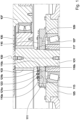
- FIG. 1 A preferred embodiment of the invention is in Fig. 1 shown.
- Fig. 1 a section of a gearbox.
- a sun shaft 101 is shown, which forms a sun gear 103.
- the sun gear 103 is provided with external teeth that mesh with the teeth of planet gears 105.
- the planet gears 105 are rotatably mounted on a planet carrier 107.
- the sun shaft 101 rotates about an axis of rotation that is identical to a central axis 109.
- an oil line 111 is provided.
- the oil line 111 has the shape of an annular cavity which is rotationally symmetrical to the central axis 109. It is formed by a base body 113 and a plate 115 screwed onto the base body 113.
- the plate 115 covers a groove 117 which runs rotationally symmetrically about the central axis 109 in the base body 113. In this way, the plate 115 together with the groove 117 forms the oil line 111.
- the plate 115 has three bores 119a, 119b, 119c running parallel to the central axis 109.
- the holes 119a, 119b, 119c are designed as through holes and open into the oil line 111.
- a first bore 119a is sealed in an oil-tight manner with a first plug 121a.
- a nozzle 123 is located in a second bore 119b.
- a third bore 119c is closed in an oil-tight manner with a second plug 121b.
- the oil is introduced into the oil line 111 and pressurized, the oil emerges from the nozzle 123.
- the nozzle 123 is positioned in the second bore 119b so that the emerging oil sprays onto the teeth of the sun gear 103.
- the base body 113 is screwed into a structure 125 fixed to the housing.
- the structure 125 fixed to the housing also forms a bearing seat for a bearing 127.
- This is supplied with oil via a bore 129 made in the base body 113.
- the bore 129 runs parallel to the central axis 109.
- the central axis 109 is aligned vertically. Therefore, oil emerging from the oil pipe 111 through the bore 129 flows into the bearing 127.
Landscapes
- Engineering & Computer Science (AREA)
- General Engineering & Computer Science (AREA)
- Mechanical Engineering (AREA)
- General Details Of Gearings (AREA)
Abstract
Description
- Die Erfindung betrifft ein Getriebe nach dem Oberbegriff von Anspruch 1.
- Aus dem Stand der Technik ist bekannt, eine sogenannte Einspritzschmierung über Rohrleitungen zu realisieren. Rohrleitungen sind von Nachteil, da sie mit anderen Teilen des Getriebes um knappen Bauraum konkurrieren. Soll eine Baureihe mit mehreren Getriebevarianten realisiert werden, ist zudem für jede Variante eine gesonderte Ausführung der Rohrleitung notwendig.
- Der Erfindung liegt die Aufgabe zugrunde, die Schmierung eines Getriebes zu verbessern. Diese Aufgabe wird gelöst durch ein Getriebe nach Anspruch 1. Bevorzugte Weiterbildungen sind in den Unteransprüchen enthalten und ergeben sich aus nachfolgender Beschreibung sowie dem in
Fig. 1 dargestellten Ausführungsbeispiel. - Das erfindungsgemäße Getriebe weist mindestens ein drehbares Bauteil auf. Das drehbare Bauteil ist relativ zu einem gehäusefesten Bezugssystem, etwa einem Getriebegehäuse selbst, drehbar gelagert. Beispielsweise kann es sich bei dem Bauteil um eine Welle, eine Nabe oder ein Zahnrad handeln.
- Das Getriebe weist darüber hinaus mindestens eine Ölleitung auf. Eine Ölleitung ist ein Mittel zum Leiten von Öl. Die Ölleitung hat bevorzugt die Form eines Kanals. Ein Kanal zeichnet sich durch einen länglichen Hohlraum mit einer Eintrittsmündung und mindestens einer Austrittsmündung aus. Der Hohlraum leitet das Öl von der Eintrittsmündung zu der mindestens einen Austrittsmündung. Das Öl tritt an dabei der Eintrittsmündung in den Hohlraum ein und verlässt ihn durch die mindestens eine Austrittsmündung verlässt.
- Die Ölleitung des erfindungsgemäßen Getriebes weist eine erste und eine zweite Austrittsöffnung auf. Die ersten und die zweite Austrittsöffnung bilden jeweils eine Austrittsmündung der Ölleitung aus.
- Erfindungsgemäß ist mindestens ein Verschlusselement für die Austrittsöffnungen vorgesehen. Mit dem Verschlusselement ist wahlweise die erste oder die zweite Austrittsöffnung öldicht verschließbar. Die erste und die zweite Austrittsöffnung sind also derart ausgebildet, dass das Verschlusselement in die jeweilige Öffnung einsetzbar ist. Insbesondere ist es möglich, das Verschlusselement aus der ersten Austrittsöffnung zu entnehmen und in die zweite Austrittsöffnung einzusetzen. Aus der zweiten Austrittsöffnung wiederum kann das Verschlusselement entnommen werden, um es in die erste Austrittsöffnung einzusetzen. Dies impliziert, dass die erste Austrittsöffnung und die zweite Austrittsöffnung baugleich sind. Die erste Austrittsöffnung und die zweite Austrittsöffnung unterscheiden sich ausschließlich hinsichtlich ihrer Positionierung innerhalb der Ölleitung.
- Da die erste und die zweite Austrittsöffnung mit dem Verschlusselement verschließbar sind, weisen die beiden Austrittsöffnungen jeweils mindestens ein Mittel zur Fixierung des Verschlusselements auf. Das mindestens eine Mittel der ersten Austrittsöffnung und das mindestens eine Mittel der zweiten Austrittsöffnung sind baugleich. Bei dem Mittel handelt es sich beispielsweise um ein Gewinde.
- Das Verschlusselement weist ein korrespondierendes Mittel auf, das mit dem Mittel der ersten Austrittsöffnung bzw. mit dem Mittel der zweiten Austrittsöffnung derart in Wechselwirkung bringbar ist, dass das Verschlusselement in der ersten Austrittsöffnung bzw. in der zweiten Austrittsöffnung fixiert wird und die jeweilige Austrittsöffnung öldicht verschließt. Bei dem Mittel des Verschlusselements kann es sich insbesondere um ein Gewinde handeln, das mit dem Gewinde der ersten Austrittsöffnung bzw. der zweiten Austrittsöffnung verschraubbar ist. Das Verschlusselement kann dann wahlweise in die ersten Austrittsöffnung oder die zweite Austrittsöffnung eingeschraubt werden.
- Neben den beschriebenen Mitteln zum Fixieren des Verschlusselements in der ersten Austrittsöffnung oder der zweiten Austrittsöffnung ist darüber hinaus bevorzugt mindestens ein Dichtelement vorgesehen, welches das Verschlusselement gegenüber der jeweiligen Austrittsöffnung öldicht abdichtet. Als Dichtelement eignet sich ein herkömmlicher O-Ring. Auch können konische Dichtflächen zur Abdichtung des Verschlusselements gegenüber der jeweiligen Austrittsöffnung vorgesehen sein.
- Genau eine der beiden Austrittsöffnungen, das heißt entweder die erste Austrittsöffnung oder die zweite Austrittsöffnung, ist vorliegend mit dem Verschlusselement verschlossen. Die andere Austrittsöffnung ist unverschlossen. Ist also die erste Austrittsöffnung mit dem Verschlusselement verschlossen, ist die zweite Austrittsöffnung unverschlossen. Ist umgekehrt die zweite Austrittsöffnung mit dem Verschlusselement verschlossen, ist die erste Austrittsöffnung unverschlossen.
- Eine unverschlossene Austrittsöffnung ist öldurchlässig. Öl, das von der Ölleitung geleitet wird, tritt also aus der unverschlossenen Austrittsöffnung aus. Entsprechend dient die unverschlossene Austrittsöffnung der Zuführung von Öl zu Schmierstellen innerhalb des Getriebes. Insbesondere lässt sich das drehbare Bauteil über die unverschlossene Austrittsöffnung mit Öl versorgen.
- Die Erfindung ist von Vorteil, da sich die Ölversorgung ohne konstruktive Änderungen an das jeweilige Getriebe anpassen lässt. Um Schmierstellen des jeweiligen Getriebes, die sich in unterschiedlichen Positionen befinden können, mit Öl zu versorgen, ist es lediglich erforderlich, nicht benötigte Austrittsöffnungen mittels des mindestens einen Verschlusselements zu verschließen.
- In einer bevorzugten Weiterbildung weist das drehbare Bauteil mindestens eine Schmierstelle auf. Eine Schmierstelle ist eine Stelle, die mit Öl versorgt werden muss. Beispielsweise müssen Verzahnungen oder Lager mit Öl versorgt werden und stellen daher Schmierstellen dar. Insbesondere kann das drehbare Bauteil eine Schmierstelle in Gestalt einer mit Öl zu versorgenden Verzahnung oder eines mit Öl zu versorgenden Lagers aufweisen.
- Die unverschlossene Austrittsöffnung ist weiterbildungsgemäß auf die Schmierstelle gerichtet. Dies bedeutet, dass die unverschlossene Austrittsöffnung derart positioniert und ausgerichtet ist, dass das aus der Austrittsöffnung austretende Öl mindestens teilweise in die Schmierstelle gelangt, sodass die Schmierstelle mit Öl versorgt wird.
- Das Bauteil ist um eine Drehachse drehbar gelagert. In einer bevorzugten Weiterbildung sind die Austrittsöffnungen in einem unterschiedlichen Abstand zu dazu angeordnet. Dies bedeutet, dass ein Abstand der ersten Austrittsöffnung von der Mittelachse und ein Abstand der zweiten Austrittsöffnung von der Mittelachse sich voneinander unterscheiden.
- Mit Abstand der Öffnungen wird der Abstand beliebiger, für beide Öffnungen nach gleichen Kriterien zu wählender Referenzpunkte von der Mittelachse bezeichnet. Bei den Referenzpunkten kann es sich etwa um Mittelpunkte der Öffnungen handeln. Auch kommt als Referenzpunkt der Punkt der jeweiligen Öffnung infrage, dessen Abstand zu der Mittelachse geringer ist als die Abstände der übrigen Punkte der jeweiligen Öffnung. In dem Fall bildet der Referenzpunkt einen Punkt der jeweiligen Öffnung, dessen Abstand zu der Drehachse minimal ist.
- Durch die unterschiedlichen Abstände der Austrittsöffnungen zu der Drehachse lässt sich eine vereinfachte eine Anpassung an drehbare Schmierstellen erzielen. So wird je nach Abstand der drehbaren Schmierstelle von der Drehachse die erste Austrittsöffnung verschlossen, während die zweite Austrittsöffnung unverschlossen bleibt, oder die zweite Austrittsöffnung wird verschlossen, während die erste Austrittsöffnung unverschlossen bleibt.
- Bevorzugt ist die Ölleitung als Ringkanal weitergebildet. Ein Ringkanal hat eine rotationssymmetrische Grundform. Die Grundform eines Körpers bezeichnet die Form eines ursprünglichen Körpers, aus dem der erstgenannte Körper durch Eliminieren einzelner Bereiche, etwa durch Einfügen von Aussparungen, und/oder durch Hinzufügen einzelner Bereiche entstanden ist.
- Aus der rotationssymmetrischen Grundform des Ringkanals, ergibt sich eine rotationssymmetrische Grundform des ölleitenden Hohlraums. Die Grundform eines Hohlraums bezeichnet analog zu der Grundform eines Körpers die Form eines ursprünglichen Hohlraums, aus dem der erstgenannte Hohlraum durch Eliminieren einzelner Bereiche, etwa durch Hinzufügen einzelner Bereiche des Körpers, der den Hohlraum ausbildet, und/oder durch Hinzufügen einzelner Bereiche, etwa durch Einfügen von Aussparungen in den Körper, der den Hohlraum bildet, entstanden ist.
- Eine Mittelachse bzw. Symmetrieachse des Ringkanals stimmt weiterbildungsgemäß mit der Drehachse des drehbaren Bauteils überein.
- Die Weiterbildung ist von Vorteil, da sie die Ölversorgung unabhängig von einer Winkellage der Ölleitung bezüglich der Drehachse des drehbaren Bauteils sicherstellt. Ist die Ölleitung als Ringkanal ausgebildet, bleiben der Abstand der ersten Austrittsöffnung von der Drehachse und der Abstand der zweiten Austrittsöffnung von der Drehachse unabhängig von der Winkellage der Ölleitung konstant. Dadurch verringert sich das Risiko, dass es infolge eines fehlerhaften Einbaus der Ölleitung zu einer Mangelschmierung kommt.
- Bevorzugt ist das Getriebe mit mindestens einer Nut und mindestens einer Platte weitergebildet. Eine Nut ist eine längliche Vertiefung einer Oberfläche. Sie zeichnet sich gegenüber anderen Vertiefungen einer Oberfläche durch einen entlang des Verlaufs der Nut unveränderlichen Querschnitt aus. Der Querschnitt ist also gegenüber einer orthogonal zu einer den Verlauf der Nut beschreibenden Kurve ausgerichteten Schnittebene invariant.
- Eine Platte ist ein Bauteil, für das Folgendes gilt: Jede Abmessung bzw. Ausdehnung des Bauteils parallel zu einer Referenzebene ist größer als jede Abmessung des Bauteils orthogonal zu der Ebene. Es handelt sich also um ein Bauteil, dessen räumliche Erstreckung entlang der Referenzebene die räumliche Erstreckung des Bauteils orthogonal dazu immer, d.h. in sämtlichen Kombinationen von miteinander zu vergleichenden Abmessungen übertrifft.
- Die Platte weist weiterbildungsgemäß die erste Austrittsöffnung und die zweite Austrittsöffnung auf. Weiterhin deckt die Platte die Nut ab. Insbesondere deckt die Platte die Nut öldicht ab. Dies bedeutet, dass zwischen den Rändern der Nut und der Platte kein Öl austreten kann. Eine Verbindung zwischen der Platte und den Rändern der Nut ist also öldicht.
- Die Platte bildet mit der Nut einen Hohlraum. Dieser ist hat vorzugsweise, wie oben beschrieben, eine rotationssymmetrische Grundform. Die erste Austrittsöffnung und die zweite Austrittsöffnung sind ölleitend mit dem Hohlraum verbunden. Das ist genau dann der Fall, wenn die beiden Austrittsöffnungen sich zwischen den Rändern der Nut befinden.
- In einer darüber hinaus bevorzugten Weiterbildung weist das Getriebe einen Grundkörper auf, der die Nut ausbildet. Auf dem Grundkörper ist entsprechend obiger Beschreibung die Platte fixiert. Der Grundkörper ist bevorzugt in einem Gehäuse des Getriebes oder in einem gehäusefesten Bauteil fixiert. Insbesondere kann das Gehäuse selbst den Grundkörper ausbilden.
- Bevorzugt wird eine separate Ausführung des Grundkörpers und des Gehäuses derart, dass es sich bei dem Grundkörper und dem Gehäuse um separate, physisch voneinander getrennte Stücke handelt. Dies bedeutet insbesondere, dass das Gehäuse und der Grundkörper nicht einstückig miteinander verbunden sind. Eine separate Ausführung des Grundkörpers und des Gehäuses erleichtert die Montage.
- Das erfindungsgemäße Getriebe oder eine bevorzugte Weiterbildung ist vorzugsweise Teil einer Getriebebaureihe. Eine Getriebebaureihe ist eine Gesamtheit von mindestens zwei Getrieben. Es handelt sich also um eine Anordnung, die ein erstes Getriebe und ein zweites Getriebe umfasst. Bei dem ersten Getriebe und dem zweiten Getriebe handelt es sich um erfindungsgemäße Getriebe oder bevorzugte Weiterbildungen.
- Die Ölleitungen des ersten Getriebes und des zweiten Getriebes sind baugleich. Ebenso sind die Verschlusselemente des ersten Getriebes und des zweiten Getriebes baugleich. Zwei Komponenten, vorliegend die Ölleitungen bzw. Verschlusselemente, sind baugleich, wenn sie in ihren physikalischen Parametern - insbesondere hinsichtlich ihrer Material- und Geometrieeigenschaften - im Rahmen der auftretenden Fertigungstoleranzen übereinstimmen.
- Die erste Austrittsöffnung der Ölleitung des ersten Getriebes und die zweite Austrittsöffnung der Ölleitung des zweiten Getriebes sind mit dem Verschlusselement des jeweiligen Getriebes verschlossen. Dies impliziert, dass die zweite Austrittsöffnung der Ölleitung des ersten Getriebes und die erste Austrittsöffnung der Ölleitung des zweiten Getriebes unverschlossen sind.
- Ein bevorzugtes Ausführungsbeispiel der Erfindung ist in
Fig. 1 dargestellt. Im Einzelnen zeigt:
Fig. 1 einen Ausschnitt eines Getriebes. - In
Fig. 1 ist eine Sonnenwelle 101 dargestellt, die ein Sonnenrad 103 ausbildet. Das Sonnenrad 103 ist mit einer Außenverzahnung versehen, die mit den Verzahnungen von Planetenrädern 105 kämmt. Die Planetenräder 105 sind drehbar auf einem Planetenträger 107 gelagert. Die Sonnenwelle 101 dreht sich um eine Drehachse, die mit einer Mittelachse 109 identisch ist. - Um das Sonnenrad 103 mit Öl zu versorgen, ist eine Ölleitung 111 vorgesehen. Die Ölleitung 111 hat die Form eines ringförmigen Hohlraums, der zu der Mittelachse 109 rotationssymmetrisch ist. Sie wird gebildet durch einen Grundkörper 113 und eine auf den Grundkörper 113 aufgeschraubte Platte 115. Die Platte 115 deckt eine in dem Grundkörper 113 rotationssymmetrisch um die Mittelachse 109 verlaufende Nut 117 ab. Auf die Weise bildet die Platte 115 zusammen mit der Nut 117 die Ölleitung 111.
- Die Platte 115 weist drei parallel zu der Mittelachse 109 verlaufende Bohrungen 119a, 119b, 119c auf. Die Bohrungen 119a, 119b, 119c sind als Durchgangsbohrungen ausgeführt und münden in die Ölleitung 111.
- Eine erste Bohrung 119a ist mit einem ersten Stopfen 121a öldicht verschlossen. In einer zweiten Bohrung 119b befindet sich eine Düse 123. Eine dritte Bohrung 119c ist mit einem zweiten Stopfen 121b öldicht verschlossen.
- Wird Öl in die Ölleitung 111 eingeleitet und mit Druck beaufschlagt, tritt das Öl aus der Düse 123 aus. Die Düse 123 ist in der zweiten Bohrung 119b so positioniert, dass das austretende Öl auf die Verzahnung des Sonnenrads 103 spritzt.
- Der Grundkörper 113 ist in einer gehäusefesten Struktur 125 verschraubt. Die gehäusefeste Struktur 125 bildet zudem einen Lagersitz für ein Lager 127. Dieses wird über eine in den Grundkörper 113 eingebrachte Bohrung 129 mit Öl versorgt. Die Bohrung 129 verläuft parallel zu der Mittelachse 109. Die Mittelachse 109 ist senkrecht ausgerichtet. Daher fließt Öl, das aus der Ölleitung 111 durch die Bohrung 129 austritt, in das Lager 127.
-
- 101
- Sonnenwelle
- 103
- Sonnenrad
- 105
- Planetenrad
- 107
- Planetenträger
- 109
- Mittelachse
- 111
- Ölleitung
- 113
- Grundkörper
- 115
- Platte
- 117
- Nut
- 119a
- erste Bohrung
- 119b
- zweite Bohrung
- 119c
- dritte Bohrung
- 121a
- erste Stopfen
- 121b
- zweiter Stopfen
- 123
- Düse
- 125
- gehäusefeste Struktur
- 127
- Lager
- 129
- Bohrung
Claims (7)
- Getriebe mit mindestens einem drehbaren Bauteil (101, 103) und mindestens einer Ölleitung (111); gekennzeichnet durch
mindestens ein Verschlusselement (121a), mit dem wahlweise eine erste und eine zweite Austrittsöffnung (119a, 119b) der Ölleitung (111) verschließbar ist; wobei eine der Austrittsöffnungen (119a) mit dem Verschlusselement (121a) verschlossen und eine der Austrittsöffnungen (119b) unverschlossen ist. - Getriebe nach Anspruch 1; dadurch gekennzeichnet, dass
das Bauteil (101, 103) mindestens eine Schmierstelle (103) aufweist; wobei die unverschlossene Austrittsöffnung (119b) auf die Schmierstelle (103) gerichtet ist. - Getriebe nach einem der vorhergehenden Ansprüche; dadurch gekennzeichnet, dass
die Austrittsöffnungen (119a, 119b) in einem unterschiedlichen Abstand zu einer Drehachse des Bauteils angeordnet sind. - Getriebe nach einem der vorhergehenden Ansprüche; dadurch gekennzeichnet, dass
die Ölleitung (111) als Ringkanal ausgebildet ist, dessen Mittelachse (109) mit einer Drehachse des Bauteils (101, 103) übereinstimmt. - Getriebe nach einem der vorhergehenden Ansprüche; gekennzeichnet durch mindestens eine Nut (117) und mindestens eine Platte (115); wobei
die Platte (115) die Austrittsöffnungen (119a, 119b) aufweist und die Nut (117) abdeckt. - Getriebe nach dem vorhergehenden Anspruch; gekennzeichnet durch einen Grundkörper (113), der die Nut (117) aufweist, und auf dem die Platte (115) fixiert ist.
- Getriebebaureihe; gekennzeichnet durchein erstes Getriebe nach einem der vorhergehenden Ansprüche und ein zweites Getriebe nach einem der vorhergehenden Ansprüche; wobeijeweils die Ölleitungen (111) und die Verschlusselemente (121a) des ersten Getriebes und des zweiten Getriebes baugleich sind; wobeidie erste Austrittsöffnung (119a) der Ölleitung (111) des ersten Getriebes und die zweite Austrittsöffnung (119b) der Ölleitung (111) des zweiten Getriebes verschlossen sind.
Applications Claiming Priority (2)
| Application Number | Priority Date | Filing Date | Title |
|---|---|---|---|
| DE102020203438.9A DE102020203438A1 (de) | 2020-03-18 | 2020-03-18 | Variantenreduzierte Einspritzschmierung |
| EP21157282.1A EP3882495B1 (de) | 2020-03-18 | 2021-02-16 | Variantenreduzierte einspritzschmierung |
Related Parent Applications (2)
| Application Number | Title | Priority Date | Filing Date |
|---|---|---|---|
| EP21157282.1A Division EP3882495B1 (de) | 2020-03-18 | 2021-02-16 | Variantenreduzierte einspritzschmierung |
| EP21157282.1A Division-Into EP3882495B1 (de) | 2020-03-18 | 2021-02-16 | Variantenreduzierte einspritzschmierung |
Publications (3)
| Publication Number | Publication Date |
|---|---|
| EP4286711A2 true EP4286711A2 (de) | 2023-12-06 |
| EP4286711A3 EP4286711A3 (de) | 2024-03-06 |
| EP4286711B1 EP4286711B1 (de) | 2025-06-11 |
Family
ID=74661264
Family Applications (2)
| Application Number | Title | Priority Date | Filing Date |
|---|---|---|---|
| EP21157282.1A Active EP3882495B1 (de) | 2020-03-18 | 2021-02-16 | Variantenreduzierte einspritzschmierung |
| EP23203787.9A Active EP4286711B1 (de) | 2020-03-18 | 2021-02-16 | Variantenreduzierte einspritzschmierung |
Family Applications Before (1)
| Application Number | Title | Priority Date | Filing Date |
|---|---|---|---|
| EP21157282.1A Active EP3882495B1 (de) | 2020-03-18 | 2021-02-16 | Variantenreduzierte einspritzschmierung |
Country Status (4)
| Country | Link |
|---|---|
| EP (2) | EP3882495B1 (de) |
| DE (1) | DE102020203438A1 (de) |
| ES (1) | ES2978817T3 (de) |
| FI (2) | FI3882495T3 (de) |
Family Cites Families (5)
| Publication number | Priority date | Publication date | Assignee | Title |
|---|---|---|---|---|
| DE19912328A1 (de) | 1999-03-19 | 2000-09-21 | Zahnradfabrik Friedrichshafen | Vorrichtung zur Ölführung in einem Getriebe eines Kraftfahrzeuges |
| JP4690180B2 (ja) | 2005-11-21 | 2011-06-01 | 日立建機株式会社 | 遊星歯車減速装置 |
| DE102007020453B4 (de) | 2007-04-27 | 2012-05-16 | Sew-Eurodrive Gmbh & Co. Kg | Getriebe, Schmiermittel-Kreislaufsystem und Getriebebaureihe |
| US9810310B2 (en) | 2014-04-07 | 2017-11-07 | Eaton Corporation | Multi-component fluid distribution system |
| EP3743641B1 (de) * | 2018-01-22 | 2021-11-17 | Volvo Truck Corporation | Vorrichtung zur steuerung der schmierung in einem stufengetriebe mit einem verzweigungsabschnitt |
-
2020
- 2020-03-18 DE DE102020203438.9A patent/DE102020203438A1/de not_active Ceased
-
2021
- 2021-02-16 FI FIEP21157282.1T patent/FI3882495T3/fi active
- 2021-02-16 ES ES21157282T patent/ES2978817T3/es active Active
- 2021-02-16 EP EP21157282.1A patent/EP3882495B1/de active Active
- 2021-02-16 FI FIEP23203787.9T patent/FI4286711T3/fi active
- 2021-02-16 EP EP23203787.9A patent/EP4286711B1/de active Active
Also Published As
| Publication number | Publication date |
|---|---|
| EP3882495A1 (de) | 2021-09-22 |
| FI3882495T3 (fi) | 2024-05-14 |
| EP4286711A3 (de) | 2024-03-06 |
| FI4286711T3 (fi) | 2025-09-11 |
| EP4286711B1 (de) | 2025-06-11 |
| ES2978817T3 (es) | 2024-09-20 |
| DE102020203438A1 (de) | 2021-09-23 |
| EP3882495B1 (de) | 2024-02-07 |
Similar Documents
| Publication | Publication Date | Title |
|---|---|---|
| DE102008064740B3 (de) | Baureihe von Getriebevarianten | |
| EP0764798B1 (de) | Planetenrad-Trägeranordnung mit Axialabstützung | |
| DE69527230T2 (de) | Lager | |
| DE102007020453B4 (de) | Getriebe, Schmiermittel-Kreislaufsystem und Getriebebaureihe | |
| DE69603709T2 (de) | Handgelenk für industrieroboter | |
| DE102008000900A1 (de) | Planetengetriebe | |
| DE102004034736A1 (de) | Differential für eine Fahrzeugachse | |
| DE69712577T2 (de) | Verfahren zum Zusammenbau eines Planetenuntersetzungsgetriebes und Planetenuntersetzungsgetriebe | |
| DE102018219011B3 (de) | Schmierstoffversorgung eines Planetengleitlagers | |
| DE102007019642B4 (de) | Fluiddynamisches Lagersystem | |
| EP3882495B1 (de) | Variantenreduzierte einspritzschmierung | |
| EP2484934B1 (de) | Baugruppe umfassend ein Planetengetriebe | |
| DE102016202533A1 (de) | Schmierung einer Steckverzahnung | |
| DE69229818T2 (de) | Kühlungsysteme in Gewindebohrgeräten, verwendbar mit Hochdruck | |
| DE10337908A1 (de) | Vorrichtung zur Ölzuführung in einem Getriebe eines Kraftfahrzeuges | |
| DE3733567C1 (de) | Getriebegehaeuse mit einer Lagerung fuer eine mindestens ein Zahnrad tragende Welle | |
| DE202014105655U1 (de) | Verbindung | |
| DE69011271T2 (de) | Schmiereinrichtung für ein Zahnrädergetriebe. | |
| EP3882493B1 (de) | Planetenträger mit rinne zur versorgung einer passverzahnung mit öl | |
| DE1625006B1 (de) | Stirnradgetriebe mit Spielausgleich bei Wellen mit veraenderlichem Abstand | |
| EP3882491B1 (de) | Stützring mit ölbohrungen | |
| DE102016217146A1 (de) | Variable Nockenwellensteuerung | |
| DE102015215173A1 (de) | Hohlrad mit Zentrierstift | |
| DE3418552C2 (de) | Anordnung zur Schmierung von Getrieben | |
| DE102025109796B3 (de) | Schmierungsstruktur für eine Planetengetriebevorrichtung |
Legal Events
| Date | Code | Title | Description |
|---|---|---|---|
| PUAI | Public reference made under article 153(3) epc to a published international application that has entered the european phase |
Free format text: ORIGINAL CODE: 0009012 |
|
| STAA | Information on the status of an ep patent application or granted ep patent |
Free format text: STATUS: THE APPLICATION HAS BEEN PUBLISHED |
|
| AC | Divisional application: reference to earlier application |
Ref document number: 3882495 Country of ref document: EP Kind code of ref document: P |
|
| AK | Designated contracting states |
Kind code of ref document: A2 Designated state(s): AL AT BE BG CH CY CZ DE DK EE ES FI FR GB GR HR HU IE IS IT LI LT LU LV MC MK MT NL NO PL PT RO RS SE SI SK SM TR |
|
| REG | Reference to a national code |
Ref legal event code: R079 Ipc: F16H0057040000 Ref country code: DE Ref legal event code: R079 Ref document number: 502021007746 Country of ref document: DE Free format text: PREVIOUS MAIN CLASS: F16H0057033000 Ipc: F16H0057040000 |
|
| PUAL | Search report despatched |
Free format text: ORIGINAL CODE: 0009013 |
|
| AK | Designated contracting states |
Kind code of ref document: A3 Designated state(s): AL AT BE BG CH CY CZ DE DK EE ES FI FR GB GR HR HU IE IS IT LI LT LU LV MC MK MT NL NO PL PT RO RS SE SI SK SM TR |
|
| RIC1 | Information provided on ipc code assigned before grant |
Ipc: F16H 57/033 20120101ALI20240126BHEP Ipc: F16H 57/04 20100101AFI20240126BHEP |
|
| STAA | Information on the status of an ep patent application or granted ep patent |
Free format text: STATUS: REQUEST FOR EXAMINATION WAS MADE |
|
| 17P | Request for examination filed |
Effective date: 20240807 |
|
| RBV | Designated contracting states (corrected) |
Designated state(s): AL AT BE BG CH CY CZ DE DK EE ES FI FR GB GR HR HU IE IS IT LI LT LU LV MC MK MT NL NO PL PT RO RS SE SI SK SM TR |
|
| GRAP | Despatch of communication of intention to grant a patent |
Free format text: ORIGINAL CODE: EPIDOSNIGR1 |
|
| STAA | Information on the status of an ep patent application or granted ep patent |
Free format text: STATUS: GRANT OF PATENT IS INTENDED |
|
| INTG | Intention to grant announced |
Effective date: 20250130 |
|
| GRAS | Grant fee paid |
Free format text: ORIGINAL CODE: EPIDOSNIGR3 |
|
| GRAA | (expected) grant |
Free format text: ORIGINAL CODE: 0009210 |
|
| STAA | Information on the status of an ep patent application or granted ep patent |
Free format text: STATUS: THE PATENT HAS BEEN GRANTED |
|
| AC | Divisional application: reference to earlier application |
Ref document number: 3882495 Country of ref document: EP Kind code of ref document: P |
|
| AK | Designated contracting states |
Kind code of ref document: B1 Designated state(s): AL AT BE BG CH CY CZ DE DK EE ES FI FR GB GR HR HU IE IS IT LI LT LU LV MC MK MT NL NO PL PT RO RS SE SI SK SM TR |
|
| REG | Reference to a national code |
Ref country code: GB Ref legal event code: FG4D Free format text: NOT ENGLISH |
|
| REG | Reference to a national code |
Ref country code: CH Ref legal event code: EP |
|
| REG | Reference to a national code |
Ref country code: DE Ref legal event code: R096 Ref document number: 502021007746 Country of ref document: DE |
|
| REG | Reference to a national code |
Ref country code: IE Ref legal event code: FG4D Free format text: LANGUAGE OF EP DOCUMENT: GERMAN |
|
| REG | Reference to a national code |
Ref country code: FI Ref legal event code: FGE |
|
| PG25 | Lapsed in a contracting state [announced via postgrant information from national office to epo] |
Ref country code: ES Free format text: LAPSE BECAUSE OF FAILURE TO SUBMIT A TRANSLATION OF THE DESCRIPTION OR TO PAY THE FEE WITHIN THE PRESCRIBED TIME-LIMIT Effective date: 20250611 |
|
| REG | Reference to a national code |
Ref country code: LT Ref legal event code: MG9D |
|
| PG25 | Lapsed in a contracting state [announced via postgrant information from national office to epo] |
Ref country code: GR Free format text: LAPSE BECAUSE OF FAILURE TO SUBMIT A TRANSLATION OF THE DESCRIPTION OR TO PAY THE FEE WITHIN THE PRESCRIBED TIME-LIMIT Effective date: 20250912 Ref country code: NO Free format text: LAPSE BECAUSE OF FAILURE TO SUBMIT A TRANSLATION OF THE DESCRIPTION OR TO PAY THE FEE WITHIN THE PRESCRIBED TIME-LIMIT Effective date: 20250911 |
|
| REG | Reference to a national code |
Ref country code: NL Ref legal event code: MP Effective date: 20250611 |
|
| PG25 | Lapsed in a contracting state [announced via postgrant information from national office to epo] |
Ref country code: BG Free format text: LAPSE BECAUSE OF FAILURE TO SUBMIT A TRANSLATION OF THE DESCRIPTION OR TO PAY THE FEE WITHIN THE PRESCRIBED TIME-LIMIT Effective date: 20250611 |
|
| PG25 | Lapsed in a contracting state [announced via postgrant information from national office to epo] |
Ref country code: HR Free format text: LAPSE BECAUSE OF FAILURE TO SUBMIT A TRANSLATION OF THE DESCRIPTION OR TO PAY THE FEE WITHIN THE PRESCRIBED TIME-LIMIT Effective date: 20250611 |
|
| PG25 | Lapsed in a contracting state [announced via postgrant information from national office to epo] |
Ref country code: RS Free format text: LAPSE BECAUSE OF FAILURE TO SUBMIT A TRANSLATION OF THE DESCRIPTION OR TO PAY THE FEE WITHIN THE PRESCRIBED TIME-LIMIT Effective date: 20250911 |
|
| PG25 | Lapsed in a contracting state [announced via postgrant information from national office to epo] |
Ref country code: LV Free format text: LAPSE BECAUSE OF FAILURE TO SUBMIT A TRANSLATION OF THE DESCRIPTION OR TO PAY THE FEE WITHIN THE PRESCRIBED TIME-LIMIT Effective date: 20250611 |
|
| PG25 | Lapsed in a contracting state [announced via postgrant information from national office to epo] |
Ref country code: NL Free format text: LAPSE BECAUSE OF FAILURE TO SUBMIT A TRANSLATION OF THE DESCRIPTION OR TO PAY THE FEE WITHIN THE PRESCRIBED TIME-LIMIT Effective date: 20250611 |
|
| PG25 | Lapsed in a contracting state [announced via postgrant information from national office to epo] |
Ref country code: PT Free format text: LAPSE BECAUSE OF FAILURE TO SUBMIT A TRANSLATION OF THE DESCRIPTION OR TO PAY THE FEE WITHIN THE PRESCRIBED TIME-LIMIT Effective date: 20251013 |
|
| PG25 | Lapsed in a contracting state [announced via postgrant information from national office to epo] |
Ref country code: IS Free format text: LAPSE BECAUSE OF FAILURE TO SUBMIT A TRANSLATION OF THE DESCRIPTION OR TO PAY THE FEE WITHIN THE PRESCRIBED TIME-LIMIT Effective date: 20251011 |
|
| PG25 | Lapsed in a contracting state [announced via postgrant information from national office to epo] |
Ref country code: SM Free format text: LAPSE BECAUSE OF FAILURE TO SUBMIT A TRANSLATION OF THE DESCRIPTION OR TO PAY THE FEE WITHIN THE PRESCRIBED TIME-LIMIT Effective date: 20250611 |
|
| PGFP | Annual fee paid to national office [announced via postgrant information from national office to epo] |
Ref country code: FI Payment date: 20251230 Year of fee payment: 6 |
|
| PG25 | Lapsed in a contracting state [announced via postgrant information from national office to epo] |
Ref country code: CZ Free format text: LAPSE BECAUSE OF FAILURE TO SUBMIT A TRANSLATION OF THE DESCRIPTION OR TO PAY THE FEE WITHIN THE PRESCRIBED TIME-LIMIT Effective date: 20250611 |
|
| PG25 | Lapsed in a contracting state [announced via postgrant information from national office to epo] |
Ref country code: PL Free format text: LAPSE BECAUSE OF FAILURE TO SUBMIT A TRANSLATION OF THE DESCRIPTION OR TO PAY THE FEE WITHIN THE PRESCRIBED TIME-LIMIT Effective date: 20250611 |
|
| PG25 | Lapsed in a contracting state [announced via postgrant information from national office to epo] |
Ref country code: EE Free format text: LAPSE BECAUSE OF FAILURE TO SUBMIT A TRANSLATION OF THE DESCRIPTION OR TO PAY THE FEE WITHIN THE PRESCRIBED TIME-LIMIT Effective date: 20250611 |
|
| PG25 | Lapsed in a contracting state [announced via postgrant information from national office to epo] |
Ref country code: SK Free format text: LAPSE BECAUSE OF FAILURE TO SUBMIT A TRANSLATION OF THE DESCRIPTION OR TO PAY THE FEE WITHIN THE PRESCRIBED TIME-LIMIT Effective date: 20250611 |
|
| REG | Reference to a national code |
Ref country code: CH Ref legal event code: U11 Free format text: ST27 STATUS EVENT CODE: U-0-0-U10-U11 (AS PROVIDED BY THE NATIONAL OFFICE) Effective date: 20260301 |
|
| REG | Reference to a national code |
Ref country code: DE Ref legal event code: R097 Ref document number: 502021007746 Country of ref document: DE |
|
| PG25 | Lapsed in a contracting state [announced via postgrant information from national office to epo] |
Ref country code: DK Free format text: LAPSE BECAUSE OF FAILURE TO SUBMIT A TRANSLATION OF THE DESCRIPTION OR TO PAY THE FEE WITHIN THE PRESCRIBED TIME-LIMIT Effective date: 20250611 |
|
| PGFP | Annual fee paid to national office [announced via postgrant information from national office to epo] |
Ref country code: DE Payment date: 20251224 Year of fee payment: 6 |
|
| PGFP | Annual fee paid to national office [announced via postgrant information from national office to epo] |
Ref country code: AT Payment date: 20260127 Year of fee payment: 6 |
|
| PG25 | Lapsed in a contracting state [announced via postgrant information from national office to epo] |
Ref country code: IT Free format text: LAPSE BECAUSE OF FAILURE TO SUBMIT A TRANSLATION OF THE DESCRIPTION OR TO PAY THE FEE WITHIN THE PRESCRIBED TIME-LIMIT Effective date: 20250611 |
|
| PLBE | No opposition filed within time limit |
Free format text: ORIGINAL CODE: 0009261 |
|
| STAA | Information on the status of an ep patent application or granted ep patent |
Free format text: STATUS: NO OPPOSITION FILED WITHIN TIME LIMIT |
|
| PGFP | Annual fee paid to national office [announced via postgrant information from national office to epo] |
Ref country code: CH Payment date: 20260301 Year of fee payment: 6 |
|
| REG | Reference to a national code |
Ref country code: CH Ref legal event code: L10 Free format text: ST27 STATUS EVENT CODE: U-0-0-L10-L00 (AS PROVIDED BY THE NATIONAL OFFICE) Effective date: 20260423 |
|
| 26N | No opposition filed |
Effective date: 20260312 |
|
| PG25 | Lapsed in a contracting state [announced via postgrant information from national office to epo] |
Ref country code: LT Free format text: LAPSE BECAUSE OF FAILURE TO SUBMIT A TRANSLATION OF THE DESCRIPTION OR TO PAY THE FEE WITHIN THE PRESCRIBED TIME-LIMIT Effective date: 20250611 |
|
| PG25 | Lapsed in a contracting state [announced via postgrant information from national office to epo] |
Ref country code: SE Free format text: LAPSE BECAUSE OF FAILURE TO SUBMIT A TRANSLATION OF THE DESCRIPTION OR TO PAY THE FEE WITHIN THE PRESCRIBED TIME-LIMIT Effective date: 20250611 |