EP4286661A1 - Method and device for controlling a steam turbine - Google Patents
Method and device for controlling a steam turbine Download PDFInfo
- Publication number
- EP4286661A1 EP4286661A1 EP22176496.2A EP22176496A EP4286661A1 EP 4286661 A1 EP4286661 A1 EP 4286661A1 EP 22176496 A EP22176496 A EP 22176496A EP 4286661 A1 EP4286661 A1 EP 4286661A1
- Authority
- EP
- European Patent Office
- Prior art keywords
- valve system
- servo valve
- control
- primary
- steam turbine
- Prior art date
- Legal status (The legal status is an assumption and is not a legal conclusion. Google has not performed a legal analysis and makes no representation as to the accuracy of the status listed.)
- Withdrawn
Links
- 238000000034 method Methods 0.000 title claims abstract description 37
- 230000001960 triggered effect Effects 0.000 claims description 17
- 238000009434 installation Methods 0.000 claims description 12
- 230000000670 limiting effect Effects 0.000 claims description 6
- 239000003921 oil Substances 0.000 description 73
- 239000012530 fluid Substances 0.000 description 6
- 230000000694 effects Effects 0.000 description 5
- 238000011010 flushing procedure Methods 0.000 description 3
- 238000005461 lubrication Methods 0.000 description 3
- 230000007257 malfunction Effects 0.000 description 3
- 238000004519 manufacturing process Methods 0.000 description 3
- 229910000831 Steel Inorganic materials 0.000 description 2
- 230000000903 blocking effect Effects 0.000 description 2
- 238000011109 contamination Methods 0.000 description 2
- 238000007599 discharging Methods 0.000 description 2
- 239000007788 liquid Substances 0.000 description 2
- 239000010687 lubricating oil Substances 0.000 description 2
- 238000007789 sealing Methods 0.000 description 2
- 239000007787 solid Substances 0.000 description 2
- 239000010959 steel Substances 0.000 description 2
- GRYLNZFGIOXLOG-UHFFFAOYSA-N Nitric acid Chemical compound O[N+]([O-])=O GRYLNZFGIOXLOG-UHFFFAOYSA-N 0.000 description 1
- 238000009825 accumulation Methods 0.000 description 1
- 230000002411 adverse Effects 0.000 description 1
- 238000009530 blood pressure measurement Methods 0.000 description 1
- 238000004140 cleaning Methods 0.000 description 1
- 230000006835 compression Effects 0.000 description 1
- 238000007906 compression Methods 0.000 description 1
- 238000007796 conventional method Methods 0.000 description 1
- 238000001816 cooling Methods 0.000 description 1
- 230000001934 delay Effects 0.000 description 1
- 238000005189 flocculation Methods 0.000 description 1
- 230000016615 flocculation Effects 0.000 description 1
- 230000006870 function Effects 0.000 description 1
- 238000007689 inspection Methods 0.000 description 1
- 239000000463 material Substances 0.000 description 1
- 238000012544 monitoring process Methods 0.000 description 1
- 229910017604 nitric acid Inorganic materials 0.000 description 1
- GQPLMRYTRLFLPF-UHFFFAOYSA-N nitrous oxide Inorganic materials [O-][N+]#N GQPLMRYTRLFLPF-UHFFFAOYSA-N 0.000 description 1
- 239000002245 particle Substances 0.000 description 1
- 230000009993 protective function Effects 0.000 description 1
- 230000002829 reductive effect Effects 0.000 description 1
- 230000000630 rising effect Effects 0.000 description 1
- 230000003068 static effect Effects 0.000 description 1
- 239000000126 substance Substances 0.000 description 1
- 230000008646 thermal stress Effects 0.000 description 1
Images
Classifications
-
- F—MECHANICAL ENGINEERING; LIGHTING; HEATING; WEAPONS; BLASTING
- F01—MACHINES OR ENGINES IN GENERAL; ENGINE PLANTS IN GENERAL; STEAM ENGINES
- F01K—STEAM ENGINE PLANTS; STEAM ACCUMULATORS; ENGINE PLANTS NOT OTHERWISE PROVIDED FOR; ENGINES USING SPECIAL WORKING FLUIDS OR CYCLES
- F01K7/00—Steam engine plants characterised by the use of specific types of engine; Plants or engines characterised by their use of special steam systems, cycles or processes; Control means specially adapted for such systems, cycles or processes; Use of withdrawn or exhaust steam for feed-water heating
- F01K7/16—Steam engine plants characterised by the use of specific types of engine; Plants or engines characterised by their use of special steam systems, cycles or processes; Control means specially adapted for such systems, cycles or processes; Use of withdrawn or exhaust steam for feed-water heating the engines being only of turbine type
- F01K7/165—Controlling means specially adapted therefor
Definitions
- the present disclosure relates to a method and a device for controlling a steam turbine, in which the steam turbine is controlled via a primary servo valve system as a main control circuit and a secondary servo valve system as a backup control circuit, the servo piston of the secondary servo valve system being kept in constant motion.
- Turbo-compressors are generally used when large gas volume flows have to be compressed, for example in compression installations for increasing the pressure in gas pipelines, as blowers in blast furnaces or steel mills, in air or gas liquefaction plants, as air or nitrous gas compressors in nitric acid plants, in petrochemical plants and refineries or as vacuum blowers in the paper industry.
- the choice of the drive unit for the turbo-compressor depends on the application. Whilst gas turbines are employed in gas pipeline and offshore applications, electric motors with frequency inverters are mostly used as a drive for small and medium power requirements. In plants in which sufficient and reliable amounts of steam is available, as is generally the case in chemical plants, steel mills or ironworks, a steam turbine is preferably used as the drive.
- the steam turbine is controlled by using a steam control valve to regulate the amount of steam supplied to the turbine, so as to guarantee the rotational speed of the turbo-compressor necessary for the production process.
- the steam control valves are mostly equipped with a hydraulic control system, in which the steam flow, and thus the rotational speed of the turbo-compressor, are controlled by varying the flow rate of the hydraulic liquid. Oil is often used as the hydraulic liquid.
- CN105545842 describes a control system and a control method for synchronizing a static TRT blade actuator, the synchronization being achieved with the use of two servo valves, a manual reversing valve and an electromagnetic reversing valve.
- CN 109268347 discloses a steam turbine interruption early warning system for a set of generators, which system comprises a main oil pump, a servo switch valve, a cartridge valve, a pilot valve, a hydraulic pressure controller, a DCS control and an oil drive.
- the early warning system is to early detect interruptions, for example due to an oil leak.
- JP2022027090 relates to a method for monitoring the opening of a steam control valve for increasing or reducing the amount of steam supplied to a turbine, wherein a first alarm is triggered, if a difference between the opening of the steam control valve and a target opening is detected, and a second alarm is triggered, if the deflection of a hydraulic actuator does not match a predefined target value.
- JP 2019031941 It is the object of JP 2019031941 to provide a steam valve drive device and a stem valve that can be operated continuously, even if a non-conformity occurs in the control valve.
- This object is intended to be achieved by the steam valve drive device comprising a control device, a first control valve for controlling an amount of working fluid, a second control valve arranged parallel to the first control valve, a first and a third stop valve for interrupting the supply of a working fluid to the control valve and for discharging the working fluid from the control valve, a second and a fourth stop valve for interrupting the supply of the working fluid to a hydraulic cylinder device from the control valve and for discharging the working fluid to the control valve from the hydraulic cylinder device, and a bypass flow channel.
- the steam valve drive device continually controls the steam valve through the second control valve on the basis of a signal from the control device, closes the first and second stop valves and discharges the working fluid in the first control valve between the first and second stop valves and the first control valve via a bypass flow channel, if a malfunction occurs in the first control valve.
- the system described has the drawback that the amount of steam has to be reduced significantly during the inspection. The instabilities and fluctuations caused thereby are a problem and may have adverse effects on the process.
- the present disclosure provides a method, in which a primary servo valve system is provided as a main control circuit and a secondary servo valve system is provided as a backup control circuit for controlling a steam turbine, and in which the secondary servo valve system is continually kept in motion and flown through.
- a first subject matter of the present disclosure relates to a method for controlling a steam turbine, the method comprising the following steps:
- the method of the present disclosure keeps the secondary servo valve system, which serves as a backup in case of a failure of the primary servo valve system, is kept in motion und is constantly flown through by the control oil flow, so that a seizure of the servo piston is prevented.
- the secondary servo valve system is always operational and can take over the control of the steam turbine should the primary servo valve system fail. Costly failures of the installation and an associated production stop can be avoided in this manner.
- the first position is a discharge position of the secondary servo valve system and the second position is a supply position of the secondary servo valve system.
- the servo piston of the secondary servo valve system is continuously moved between the first position and the second position.
- the servo piston is moved from the first position to the second position within a first period t 1 .
- the servo piston is moved from the second position to the first position within a second period t 2 .
- t x may be t 1 +t 2 . Additionally or alternatively t 1 and t 2 may be equal.
- a primary control oil flow may be supplied to the primary servo valve system from an oil receptacle and may be supplied from there to an actuator via a magnetic switch valve, which actuator controls the steam supply to the steam turbine.
- a secondary control oil flow may be supplied to the secondary servo valve system from an oil receptacle and is returned into the oil receptacle via the magnetic switch valve, wherein the magnetic switch valve is controlled such that the control oil flow from the secondary servo valve system is supplied to the actuator if the primary servo valve system fails.
- the alarm is triggered if the pressure in the control oil return flow does not reach the minimum and/or the maximum pressure value within a period t z , wherein t z is equal to the sum of t 1 and x and/or t z is equal to t 2 and x, with x representing a freely selectable waiting period.
- the steam turbine drives a turbo-compressor in a petrochemical installation, in particular a cracker, or a generator in a power plant.
- a further subject matter of the present disclosure relates to a device for controlling a steam turbine, comprising
- the alarm system is triggered if the measured pressure value does not reach a maximum target pressure value and/or a minimum target pressure value.
- the alarm system is configured such that an alarm is triggered if the maximum target pressure value and/or the minimum target pressure value is not reached within a time period t z .
- the device is operated in a petrochemical installation.
- the device may be operated in a cracker or in a power plant.
- a first subject matter of the present disclosure relates to a method for controlling a steam turbine, the method comprising the following steps:
- the method of the present disclosure keeps the secondary servo valve system, which serves as a backup in case of a failure of the primary servo valve system, is kept in motion und is constantly flown through by the control oil flow, so that a seizure of the servo piston is prevented.
- the secondary servo valve system is always operational and can take over the control of the steam turbine should the primary servo valve system fail. Costly failures of the installation and an associated production stop can be avoided in this manner.
- a primary control oil flow is supplied from an oil receptacle to the primary servo valve system from which the control oil flow is supplied on through a magnetic switch valve to an actuator that controls the steam supply to the steam turbine.
- a secondary control oil flow is supplied from the oil receptacle to the secondary servo valve system and is returned into the oil receptacle.
- the magnetic valve is controlled such that the control oil flow is supplied from the secondary servo valve system to the actuator if the primary servo valve system fails.
- a combined lubrication oil and control oil system is used, whereby obstructions of the control valve can occur, for example due to abraded material accumulated in the oil.
- the control oil flow is returned from an oil receptacle back into the oil receptacle through the secondary servo valve system, if the secondary servo valve system is in the backup mode.
- the regular flushing of the secondary servo valve system creates a flushing effect, by which small contaminations that would otherwise accumulate in the valve are flushed away. Furthermore, the accretion of solids is prevented by the continuous movement of the servo piston.
- control oil and lubricating oil are taken from the same oil tank.
- the servo piston of the secondary servo valve system is continually moved between the first position and the second position. This continuous movement of the servo piston causes a cleaning effect on the running surfaces of the cylinder and the piston, so that an accumulation of an accretion that would cause a blocking of the cylinder is prevented. Surprisingly, it has been observed that the cyclical and continuous movement of the piston causes a certain heat input that prevents oil in the system from cooling, which would cause flocculation in the oil and would again result in a blocking of the system.
- the continuous movement of the servo piston causes a rising and falling pressure in the control oil return flow, which pressure can be used as a control function of the system. If specific target values, such as a maximum pressure value and a minimum pressure value, are not reached, one can conclude on a malfunction of the system and an alarm is triggered.
- the servo piston is moved from the first position to the second position within a first period t1, and thereby a pressure change is caused in the control oil return flow. This pressure change may in an exemplary embodiment be monitored based on target values defined in advance.
- the servo piston is moved from the second position to the first position within a second period t2, and thereby a pressure change is caused in the control oil return flow.
- the pressure change thus caused can be monitored on the basis of target values defined in advance, and thus the correct functioning of the secondary servo valve system can be monitored and maintained.
- the servo piston of the secondary servo valve system may be moved cyclically from the first position to the second position and back within a period t x .
- the method according to the disclosure provides that an alarm is triggered if the pressure in the control oil return flow does not reach the defined target values.
- This alarm can be triggered with a delay in time, so that an embodiment is in which the alarm is triggered if the pressure in the control oil return flow has not reached the minimum and/or the maximum pressure value within a period t z . In this manner, false alarms can be prevented that may be triggered by slight pressure variations in the control oil return flow.
- the control oil flow is therefore returned into the oil receptacle when the servo piston of the secondary servo valve system is in the first position or between the first position and the second position.
- a regular flushing of the secondary servo valve system is achieved by this guiding of the control oil flow, so that a clogging of the valve is prevented.
- the control method according to the disclosure is characterized in particular in that it provides for an instantaneous operational readiness of the backup control circuit if the main control circuit should fail.
- this protective function an embodiment is envisioned in which in case of a failure of the primary servo valve system, the control oil flow is supplied by the secondary servo valve system to an actuator, for example a hydraulic main steam valve, which controls the steam flow to the steam turbine. In this manner, the secondary control circuit can assume the control of the steam turbine, without a failure of the installation occurring.
- the control system of a steam turbine generally comprises a number of control and actuation units that control the steam flow supplied to the turbine.
- the servo valve systems supply the control oil flow to an actuator via a magnetic switch valve, the actuator operating a valve that controls the supply of the steam flow to the steam turbine. Should the primary servo valve system fail, the control oil flow can be supplied to the actuator from the secondary servo valve system via the magnetic switch valve and the control oil flow can thus be maintained.
- the method according to the disclosure can be used to control any optional steam turbine.
- the steam turbine drives a turbo-compressor, particularly one used in a petrochemical plant, such as a cracker.
- the steam turbine drives a generator in a power plant.
- a further subject matter of the present disclosure relates to a device for controlling a steam turbine, comprising
- the alarm system is configured such that an alarm is triggered if the maximum target pressure value and/or the minimum target pressure value is not reached within a period t z . In this manner, it is provided that false alarms are caused due to noncritical delays during pressure adjustment.
- the actuator is the main steam control valve that controls the steam flow supplied to the steam turbine.
- the device according to the present disclosure is operated in a petrochemical installation, preferably a cracker, or in a power plant.
- a control oil flow is directed from a reservoir (1), from which also the oil for the bearing lubrication and the sealing oil system of the steam turbine and the crude gas turbo-compressor (3) is taken, into the control system comprising a primary servo valve system (5) and a secondary servo valve system (6).
- the control system comprising a primary servo valve system (5) and a secondary servo valve system (6).
- a first part of the control oil flow is returned into the oil reservoir (1) via the switch valve (7), wherein the pressure in this return flow is monitored using a limiting orifice and an adjusting valve (2) as well as a pressure gauge (4). Should the pressure in the secondary servo valve system (6) not reach the predetermined target values within a defined period, an alarm will be triggered.
Landscapes
- Engineering & Computer Science (AREA)
- Chemical & Material Sciences (AREA)
- Combustion & Propulsion (AREA)
- Mechanical Engineering (AREA)
- General Engineering & Computer Science (AREA)
- Control Of Turbines (AREA)
Abstract
A method and device for controlling a steam turbine, in which the steam turbine is controlled via a primary servo valve system as a main control circuit and a secondary servo valve system as a backup control circuit, the servo piston of the secondary servo valve system being kept in constant motion.
Description
- The present disclosure relates to a method and a device for controlling a steam turbine, in which the steam turbine is controlled via a primary servo valve system as a main control circuit and a secondary servo valve system as a backup control circuit, the servo piston of the secondary servo valve system being kept in constant motion.
- Turbo-compressors are generally used when large gas volume flows have to be compressed, for example in compression installations for increasing the pressure in gas pipelines, as blowers in blast furnaces or steel mills, in air or gas liquefaction plants, as air or nitrous gas compressors in nitric acid plants, in petrochemical plants and refineries or as vacuum blowers in the paper industry. The choice of the drive unit for the turbo-compressor depends on the application. Whilst gas turbines are employed in gas pipeline and offshore applications, electric motors with frequency inverters are mostly used as a drive for small and medium power requirements. In plants in which sufficient and reliable amounts of steam is available, as is generally the case in chemical plants, steel mills or ironworks, a steam turbine is preferably used as the drive.
- Generally, the steam turbine is controlled by using a steam control valve to regulate the amount of steam supplied to the turbine, so as to guarantee the rotational speed of the turbo-compressor necessary for the production process.
- The steam control valves are mostly equipped with a hydraulic control system, in which the steam flow, and thus the rotational speed of the turbo-compressor, are controlled by varying the flow rate of the hydraulic liquid. Oil is often used as the hydraulic liquid.
- Such control systems are described in various references.
-
CN105545842 describes a control system and a control method for synchronizing a static TRT blade actuator, the synchronization being achieved with the use of two servo valves, a manual reversing valve and an electromagnetic reversing valve. -
CN 109268347 discloses a steam turbine interruption early warning system for a set of generators, which system comprises a main oil pump, a servo switch valve, a cartridge valve, a pilot valve, a hydraulic pressure controller, a DCS control and an oil drive. The early warning system is to early detect interruptions, for example due to an oil leak. -
JP2022027090 - It is the object of
JP 2019031941 - It is a further problem with such control systems that the control and lubricating oil circuits of the turbo-compressor and of the steam turbine receive the oil from the same reservoir so that a mixing of the oil flows from the two applications occurs. Due to thermal stress and contact with process media, the oil ages, forming solid particles in the process. These contaminations may cause an obstruction of the valves, in particular of the sensitive servo valves, which in the worst case may result in a failure of the installation. This problem is exacerbated in the components in which there is no constant flow or in which the flow rate is low, as for example in emergency systems which are intended to take over control of the steam turbine in case of a malfunction or a failure of the main control system. Thus, there is a risk that the emergency system does not operate and the installation comes to a standstill which generally comes with a great financial loss.
- Against this backdrop, there is thus a need to provide a method that enables a reliable control of a steam turbine.
- The present disclosure provides a method, in which a primary servo valve system is provided as a main control circuit and a secondary servo valve system is provided as a backup control circuit for controlling a steam turbine, and in which the secondary servo valve system is continually kept in motion and flown through.
- Therefore, a first subject matter of the present disclosure relates to a method for controlling a steam turbine, the method comprising the following steps:
- i) providing a primary servo valve system as a main control circuit for controlling the steam flow entering the steam turbine;
- ii) providing a secondary servo valve system as a backup control circuit for controlling the steam flow entering the steam turbine;
- iii) generating a control oil return flow from the secondary servo valve system;
- iv) cyclically moving the servo piston between the first position and the second position within a period tx and simultaneously sensing the pressure in the control oil return flow;
- v) recording the sensed pressure values while forming a maximum and a minimum pressure value;
- vi) triggering an alarm signal, if the measured pressure fails to reach a minimum and/or maximum target pressure.
- The method of the present disclosure keeps the secondary servo valve system, which serves as a backup in case of a failure of the primary servo valve system, is kept in motion und is constantly flown through by the control oil flow, so that a seizure of the servo piston is prevented. Thus, it is ensured that also the secondary servo valve system is always operational and can take over the control of the steam turbine should the primary servo valve system fail. Costly failures of the installation and an associated production stop can be avoided in this manner.
- In some embodiments, the first position is a discharge position of the secondary servo valve system and the second position is a supply position of the secondary servo valve system.
- In some embodiments, the servo piston of the secondary servo valve system is continuously moved between the first position and the second position.
- In some embodiments, the servo piston is moved from the first position to the second position within a first period t1.
- In some embodiments, the servo piston is moved from the second position to the first position within a second period t2.
- In some embodiments, tx may be t1+t2. Additionally or alternatively t1 and t2 may be equal.
- In some embodiments, a primary control oil flow may be supplied to the primary servo valve system from an oil receptacle and may be supplied from there to an actuator via a magnetic switch valve, which actuator controls the steam supply to the steam turbine. Furthermore, a secondary control oil flow may be supplied to the secondary servo valve system from an oil receptacle and is returned into the oil receptacle via the magnetic switch valve, wherein the magnetic switch valve is controlled such that the control oil flow from the secondary servo valve system is supplied to the actuator if the primary servo valve system fails.
- In some embodiments, the alarm is triggered if the pressure in the control oil return flow does not reach the minimum and/or the maximum pressure value within a period tz, wherein tz is equal to the sum of t1 and x and/or tz is equal to t2 and x, with x representing a freely selectable waiting period.
- In some embodiments, the steam turbine drives a turbo-compressor in a petrochemical installation, in particular a cracker, or a generator in a power plant.
- A further subject matter of the present disclosure relates to a device for controlling a steam turbine, comprising
- i) an oil tank containing a control oil;
- ii) a primary control circuit comprising a primary servo valve system;
- iii) a secondary control circuit comprising a secondary servo valve system;
- iv) a magnetic switch valve;
- v) a control unit for controlling the steam flow to the steam turbine and
- vi) an alarm system,
- wherein the primary control circuit and the secondary control circuit are connected to the oil tank,
- wherein the primary servo valve system and the secondary servo valve system are configured to guide the control oil flow to the magnetic switch valve,
- wherein the magnetic switch valve is controlled such that it switches from the primary servo valve system to the secondary servo valve system if the primary servo valve system is not operational;
- wherein the secondary control circuit comprises a limiting orifice, a valve and a measuring unit that are arranged between the oil tank and the secondary servo valve system;
- wherein the measuring unit is designed to measure a minimum pressure value and/or a maximum pressure value in the control oil flow, which is generated by cyclically moving a servo piston in the secondary servo valve system between a first position and a second position,
- wherein the alarm system is configured such that an alarm signal is triggered if the measured pressure value does not reach a maximum target pressure value and/or a minimum target pressure value.
- In some embodiments, the alarm system is triggered if the measured pressure value does not reach a maximum target pressure value and/or a minimum target pressure value.
- In some embodiments the alarm system is configured such that an alarm is triggered if the maximum target pressure value and/or the minimum target pressure value is not reached within a time period tz.
- In some embodiments, the device is operated in a petrochemical installation. In particular, the device may be operated in a cracker or in a power plant.
- The present disclosure is illustrated with reference to the following Figures which should by no means be understood as limiting the idea of the disclosure.
- The combination of features shown and described in the individual exemplary embodiments serves solely the purposes of explanation. According to the statements above, it is possible to dispense with a feature of an exemplary embodiment if its technical effect is of no importance in a particular application. Conversely, according to the above statements, a further feature can be added in an exemplary embodiment if its technical effect is meant to be advantageous or necessary for a particular application.
-
-
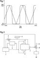
Figure 1 shows an exemplary pressure recording of the control oil return flow within the scope of the method according to the disclosure, wherein the recording shows the pressure buildup and the pressure drop which are generated by the cyclical movement of the servo piston in the secondary servo valve system. -
Figure 2 shows a schematic structure of the system according to the disclosure comprising- 1. oil reservoir
- 2. limiting orifice and adjusting valve
- 3. bearing lubrication and sealing oil system of the steam turbine and the crude gas turbo-compressor
- 4. pressure measurement secondary servo valve system
- 5. primary servo valve system
- 6. secondary servo valve system
- 7. switch valve
- 8. steam supply
- 9. steam control valve
- 10. steam turbine
- A first subject matter of the present disclosure relates to a method for controlling a steam turbine, the method comprising the following steps:
- i) providing a primary servo valve system as a main control circuit for controlling the steam flow entering the steam turbine;
- ii) providing a secondary servo valve system as a backup control circuit for controlling the steam flow entering the steam turbine;
- iii) generating a control oil return flow from the secondary servo valve system;
- iv) cyclically moving the servo piston between the first position and the second position within a period tx and simultaneously sensing the pressure in the control oil return flow;
- v) recording the sensed pressure values while forming a maximum and a minimum pressure value;
- vi) triggering an alarm signal, if the measured pressure fails to reach a minimum and/or maximum target pressure.
- The method of the present disclosure keeps the secondary servo valve system, which serves as a backup in case of a failure of the primary servo valve system, is kept in motion und is constantly flown through by the control oil flow, so that a seizure of the servo piston is prevented. Thus, it is ensured that also the secondary servo valve system is always operational and can take over the control of the steam turbine should the primary servo valve system fail. Costly failures of the installation and an associated production stop can be avoided in this manner.
- In some embodiments of the method according to the disclosure a primary control oil flow is supplied from an oil receptacle to the primary servo valve system from which the control oil flow is supplied on through a magnetic switch valve to an actuator that controls the steam supply to the steam turbine. A secondary control oil flow is supplied from the oil receptacle to the secondary servo valve system and is returned into the oil receptacle. In a further embodiment, the magnetic valve is controlled such that the control oil flow is supplied from the secondary servo valve system to the actuator if the primary servo valve system fails.
- In conventional installations, a combined lubrication oil and control oil system is used, whereby obstructions of the control valve can occur, for example due to abraded material accumulated in the oil. According to the method of the disclosure, the control oil flow is returned from an oil receptacle back into the oil receptacle through the secondary servo valve system, if the secondary servo valve system is in the backup mode. The regular flushing of the secondary servo valve system creates a flushing effect, by which small contaminations that would otherwise accumulate in the valve are flushed away. Furthermore, the accretion of solids is prevented by the continuous movement of the servo piston. Thus, upon a failure of the main control circuit, the secondary servo valve system can be used without delay to control the steam turbine, in which the control oil flow is then supplied by the secondary servo valve system to the actuator which controls the steam supply to the steam turbine. Moreover, a negative impact on the steam flow in regular operation, which is partly common in conventional methods, is prevented. In some embodiments, as part of the method of the method of the disclosure, control oil and lubricating oil are taken from the same oil tank.
- In some embodiments, the servo piston of the secondary servo valve system is continually moved between the first position and the second position. This continuous movement of the servo piston causes a cleaning effect on the running surfaces of the cylinder and the piston, so that an accumulation of an accretion that would cause a blocking of the cylinder is prevented. Surprisingly, it has been observed that the cyclical and continuous movement of the piston causes a certain heat input that prevents oil in the system from cooling, which would cause flocculation in the oil and would again result in a blocking of the system.
- The continuous movement of the servo piston causes a rising and falling pressure in the control oil return flow, which pressure can be used as a control function of the system. If specific target values, such as a maximum pressure value and a minimum pressure value, are not reached, one can conclude on a malfunction of the system and an alarm is triggered. In some embodiments of the method according to the disclosure, the servo piston is moved from the first position to the second position within a first period t1, and thereby a pressure change is caused in the control oil return flow. This pressure change may in an exemplary embodiment be monitored based on target values defined in advance.
- In a further exemplary embodiment, the servo piston is moved from the second position to the first position within a second period t2, and thereby a pressure change is caused in the control oil return flow. The pressure change thus caused can be monitored on the basis of target values defined in advance, and thus the correct functioning of the secondary servo valve system can be monitored and maintained.
- In some embodiments of the method according to the disclosure, the servo piston of the secondary servo valve system may be moved cyclically from the first position to the second position and back within a period tx. In a further exemplary embodiment tx may be characterized by the following relationship:

- The time intervals t1 and t2 can be chosen freely and can be adjusted depending on the application. In an exemplary embodiment, it further holds that t1 = t2.
- The method according to the disclosure provides that an alarm is triggered if the pressure in the control oil return flow does not reach the defined target values. This alarm can be triggered with a delay in time, so that an embodiment is in which the alarm is triggered if the pressure in the control oil return flow has not reached the minimum and/or the maximum pressure value within a period tz. In this manner, false alarms can be prevented that may be triggered by slight pressure variations in the control oil return flow. The time interval tz can be chosen freely and can be adjusted. In one embodiment, it holds that:
tz = t1 + x and/or t2 + x, where x is a freely selectable waiting period. More preferably, it holds that: 60 seconds ≤ tz ≤ 600 seconds, more preferably 120 seconds ≤ tz ≤ 300 seconds. - For the time that the main control circuit comprising the primary servo valve system operates properly, no interference by the backup control circuit has to be provided and its influence on the operation of the steam turbine should be kept as little as possible. In an exemplary embodiment, the control oil flow is therefore returned into the oil receptacle when the servo piston of the secondary servo valve system is in the first position or between the first position and the second position. In addition, a regular flushing of the secondary servo valve system is achieved by this guiding of the control oil flow, so that a clogging of the valve is prevented.
- The control method according to the disclosure is characterized in particular in that it provides for an instantaneous operational readiness of the backup control circuit if the main control circuit should fail. In the context of this protective function, an embodiment is envisioned in which in case of a failure of the primary servo valve system, the control oil flow is supplied by the secondary servo valve system to an actuator, for example a hydraulic main steam valve, which controls the steam flow to the steam turbine. In this manner, the secondary control circuit can assume the control of the steam turbine, without a failure of the installation occurring.
- The control system of a steam turbine generally comprises a number of control and actuation units that control the steam flow supplied to the turbine. In an exemplary embodiment of the method according to the disclosure, the servo valve systems supply the control oil flow to an actuator via a magnetic switch valve, the actuator operating a valve that controls the supply of the steam flow to the steam turbine. Should the primary servo valve system fail, the control oil flow can be supplied to the actuator from the secondary servo valve system via the magnetic switch valve and the control oil flow can thus be maintained.
- The method according to the disclosure can be used to control any optional steam turbine. In one embodiment, the steam turbine drives a turbo-compressor, particularly one used in a petrochemical plant, such as a cracker. In an alternative embodiment, the steam turbine drives a generator in a power plant.
- A further subject matter of the present disclosure relates to a device for controlling a steam turbine, comprising
- i) an oil tank containing a control oil;
- ii) a primary control circuit comprising a primary servo valve system;
- iii) a secondary control circuit comprising a secondary servo valve system;
- iv) a magnetic switch valve;
- v) an actuator for controlling the steam flow to the steam turbine and
- vi) an alarm system,
- wherein the primary control circuit and the secondary control circuit are connected to the oil tank,
- wherein the primary servo valve system and the secondary servo valve system are configured to guide the control oil flow to the magnetic switch valve,
- wherein the magnetic switch valve is controlled such that it switches from the primary servo valve system to the secondary servo valve system if the primary servo valve system is not operational;
- wherein the secondary control circuit comprises a limiting orifice, a valve and a measuring unit that are arranged between the oil tank and the secondary servo valve system;
- wherein the measuring unit is designed to measure a minimum pressure value and/or a maximum pressure value in the control oil flow, which is generated by cyclically moving a servo piston in the secondary servo valve system between a first position and a second position,
- wherein the alarm system is configured such that an alarm signal is triggered if the measured pressure value does not reach a maximum target pressure value and/or a minimum target pressure value.
- In an exemplary embodiment, the alarm system is configured such that an alarm is triggered if the maximum target pressure value and/or the minimum target pressure value is not reached within a period tz. In this manner, it is provided that false alarms are caused due to noncritical delays during pressure adjustment.
- In some embodiments, the actuator is the main steam control valve that controls the steam flow supplied to the steam turbine.
- In some embodiment, the device according to the present disclosure is operated in a petrochemical installation, preferably a cracker, or in a power plant.
- A control oil flow is directed from a reservoir (1), from which also the oil for the bearing lubrication and the sealing oil system of the steam turbine and the crude gas turbo-compressor (3) is taken, into the control system comprising a primary servo valve system (5) and a secondary servo valve system (6). In regular operation, after passing the secondary servo valve system (6), a first part of the control oil flow is returned into the oil reservoir (1) via the switch valve (7), wherein the pressure in this return flow is monitored using a limiting orifice and an adjusting valve (2) as well as a pressure gauge (4). Should the pressure in the secondary servo valve system (6) not reach the predetermined target values within a defined period, an alarm will be triggered.
- After passing the primary servo valve system (5), a second part of the control oil flow is supplied via the switch valve (7) to the steam control valve (9) which controls the steam supply (8) to the steam turbine (10). Should the primary servo valve system (5) fail, the control oil flow of the secondary servo valve system (6) can be supplied to the steam control valve (9) via the switch valve (7) and assume the control of the steam flow (8).
Claims (12)
- A method for controlling a steam turbine (10), the method comprising:i) providing a primary servo valve system (5) as a main control circuit for controlling the steam flow (8) entering the steam turbine (10);ii) providing a secondary servo valve system (6) as a backup control circuit for controlling the steam flow (8) entering the steam turbine (10);wherein the secondary servo valve system (6) comprises a servo piston that is freely movable between a first position and a second position;iii) generating a control oil return flow from the secondary servo valve system (6);iv) cyclically moving the servo piston between the first position and the second position within a period tx and simultaneously sensing the pressure in the control oil return flow (4);v) recording the sensed pressure values while forming a maximum and a minimum pressure value;vi) triggering an alarm signal, if the measured pressure fails to reach a minimum and/or maximum target pressure.
- The method according to claim 1, characterized in that the first position is a discharge position and the second position is a supply position.
- The method according to at least one of the preceding claims, characterized in that the servo piston of the secondary servo valve system (6) is continuously moved between the first position and the second position.
- The method according to at least one of the preceding claims, characterized in that the servo piston is moved from the first position to the second position within a first period t1.
- The method according to at least one of the preceding claims, characterized in that the servo piston is moved from the second position to the first position within a second period t2.
- The method according to at least one of the preceding claims, characterized in that tx = t1 + t2 and/or t1 = t2.
- The method according to at least one of the preceding claims, characterized in that a primary control oil flow is supplied to the primary servo valve system (5) from an oil receptacle (1) and is supplied from there to an actuator (9) via a magnetic switch valve (7), which actuator controls the steam supply (8) to the steam turbine (10), and a secondary control oil flow is supplied to the secondary servo valve system (6) from an oil receptacle (1) and is returned into the oil receptacle (1) via the magnetic switch valve (7), wherein the magnetic switch valve (7) is optionally controlled such that the control oil flow from the secondary servo valve system (6) is supplied to the actuator (9) if the primary servo valve system (5) fails.
- The method according to at least one of the preceding claims, characterized in that the alarm is triggered if the pressure in the control oil return flow does not reach the minimum and/or the maximum pressure value within a period tz, wherein tz = t1 + x and/or t2 + x, with x representing a freely selectable waiting period.
- The method according to at least one of the preceding claims, characterized in that the steam turbine (10) drives a turbo-compressor in a petrochemical installation, particularly a cracker, or a generator in a power plant.
- A device for controlling a steam turbine (10), comprising:i) an oil tank (1) containing a control oil;ii) a primary control circuit comprising a primary servo valve system (5);iii) a secondary control circuit comprising a secondary servo valve system (6);iv) a magnetic switch valve (7);v) a control unit (9) for controlling the steam supply (8) to the steam turbine (10), andvi) an alarm system,wherein the primary control circuit and the secondary control circuit are connected to the oil tank (1),wherein the primary servo valve system (5) and the secondary servo valve system (6) are configured to guide the control oil flow to the magnetic switch valve (7),wherein the magnetic switch valve (7) is controlled such that it switches from the primary servo valve system (5) to the secondary servo valve system (6) if the primary servo valve system (5) is not operational;wherein the secondary control circuit comprises a limiting orifice (2), a valve (2) and a measuring unit (4) that are arranged between the oil tank (1) and the secondary servo valve system (6);wherein the measuring unit (4) is designed to measure a minimum pressure value and/or a maximum pressure value in the control oil flow, which is generated by cyclically moving a servo piston in the secondary servo valve system (6) between a first position and a second position,wherein the alarm system is configured such that an alarm signal is triggered if the measured pressure value does not reach a maximum target pressure value and/or a minimum target pressure value.
- The device according to claim 10, characterized in that the alarm system is configured such that an alarm is triggered if the maximum target pressure value and/or the minimum target pressure value is not reached within a period tz.
- The device according to at least one of claims 10 or 11, characterized in that the device is operated in a petrochemical installation, preferably a cracker, or in a power plant.
Priority Applications (3)
| Application Number | Priority Date | Filing Date | Title |
|---|---|---|---|
| EP22176496.2A EP4286661A1 (en) | 2022-05-31 | 2022-05-31 | Method and device for controlling a steam turbine |
| EP23730024.9A EP4532902B1 (en) | 2022-05-31 | 2023-05-26 | Method and device for controlling a steam turbine |
| PCT/EP2023/064246 WO2023232704A1 (en) | 2022-05-31 | 2023-05-26 | Method and device for controlling a steam turbine |
Applications Claiming Priority (1)
| Application Number | Priority Date | Filing Date | Title |
|---|---|---|---|
| EP22176496.2A EP4286661A1 (en) | 2022-05-31 | 2022-05-31 | Method and device for controlling a steam turbine |
Publications (1)
| Publication Number | Publication Date |
|---|---|
| EP4286661A1 true EP4286661A1 (en) | 2023-12-06 |
Family
ID=81854478
Family Applications (2)
| Application Number | Title | Priority Date | Filing Date |
|---|---|---|---|
| EP22176496.2A Withdrawn EP4286661A1 (en) | 2022-05-31 | 2022-05-31 | Method and device for controlling a steam turbine |
| EP23730024.9A Active EP4532902B1 (en) | 2022-05-31 | 2023-05-26 | Method and device for controlling a steam turbine |
Family Applications After (1)
| Application Number | Title | Priority Date | Filing Date |
|---|---|---|---|
| EP23730024.9A Active EP4532902B1 (en) | 2022-05-31 | 2023-05-26 | Method and device for controlling a steam turbine |
Country Status (2)
| Country | Link |
|---|---|
| EP (2) | EP4286661A1 (en) |
| WO (1) | WO2023232704A1 (en) |
Citations (6)
| Publication number | Priority date | Publication date | Assignee | Title |
|---|---|---|---|---|
| EP0128284A1 (en) * | 1983-04-13 | 1984-12-19 | Siemens Aktiengesellschaft | Three-channel commanding and supervision apparatus for turbo machine-actuating valves |
| CN105545842A (en) | 2016-02-05 | 2016-05-04 | 魏英群 | TRT static blade actuator synchronization control system and control method |
| CN109268347A (en) | 2018-11-26 | 2019-01-25 | 湖北华电江陵发电有限公司 | Generator set and its turbine interrupt warning system |
| JP2019031941A (en) | 2017-08-08 | 2019-02-28 | 株式会社東芝 | Steam valve driving device and steam valve |
| US20200362729A1 (en) * | 2019-05-14 | 2020-11-19 | Kabushiki Kaisha Toshiba | Steam valve driving apparatus, steam valve apparatus, and steam turbine plant |
| JP2022027090A (en) | 2020-07-31 | 2022-02-10 | Hitowaケアサービス株式会社 | Intention confirmation program, intention confirmation method, terminal device, proxy work support program, proxy work support method, server and proxy work support system |
-
2022
- 2022-05-31 EP EP22176496.2A patent/EP4286661A1/en not_active Withdrawn
-
2023
- 2023-05-26 WO PCT/EP2023/064246 patent/WO2023232704A1/en not_active Ceased
- 2023-05-26 EP EP23730024.9A patent/EP4532902B1/en active Active
Patent Citations (6)
| Publication number | Priority date | Publication date | Assignee | Title |
|---|---|---|---|---|
| EP0128284A1 (en) * | 1983-04-13 | 1984-12-19 | Siemens Aktiengesellschaft | Three-channel commanding and supervision apparatus for turbo machine-actuating valves |
| CN105545842A (en) | 2016-02-05 | 2016-05-04 | 魏英群 | TRT static blade actuator synchronization control system and control method |
| JP2019031941A (en) | 2017-08-08 | 2019-02-28 | 株式会社東芝 | Steam valve driving device and steam valve |
| CN109268347A (en) | 2018-11-26 | 2019-01-25 | 湖北华电江陵发电有限公司 | Generator set and its turbine interrupt warning system |
| US20200362729A1 (en) * | 2019-05-14 | 2020-11-19 | Kabushiki Kaisha Toshiba | Steam valve driving apparatus, steam valve apparatus, and steam turbine plant |
| JP2022027090A (en) | 2020-07-31 | 2022-02-10 | Hitowaケアサービス株式会社 | Intention confirmation program, intention confirmation method, terminal device, proxy work support program, proxy work support method, server and proxy work support system |
Also Published As
| Publication number | Publication date |
|---|---|
| WO2023232704A1 (en) | 2023-12-07 |
| EP4532902B1 (en) | 2026-04-22 |
| EP4532902A1 (en) | 2025-04-09 |
Similar Documents
| Publication | Publication Date | Title |
|---|---|---|
| EP3507464B1 (en) | Tightness test evaluation module for a valve and actuator monitoring system | |
| US10233786B2 (en) | Actuator spring lifetime supervision module for a valve and actuator monitoring system | |
| CN109642469B (en) | Pilot condition assessment module for valve and actuator monitoring systems | |
| CN109643112B (en) | Advanced Start Counter Module for Valve and Actuator Monitoring Systems | |
| EP3530874B1 (en) | Erosion monitoring system | |
| JP4538153B2 (en) | Pump transportation method and apparatus | |
| US20120148382A1 (en) | Method and apparatus for the model-based monitoring of a turbomachine | |
| WO2018041849A1 (en) | Valve stroke and spindle way counter module for a valve and actuator monitoring system | |
| JP7356267B2 (en) | Anomaly detection device, anomaly detection method and program | |
| US10066501B2 (en) | Solid particle erosion indicator module for a valve and actuator monitoring system | |
| EP4532902B1 (en) | Method and device for controlling a steam turbine | |
| EP3290654A1 (en) | Flexible service interval counter module for a valve and actuator monitoring system | |
| US10871081B2 (en) | Creep damage indicator module for a valve and actuator monitoring system | |
| US11371382B2 (en) | Steam-using facility monitoring system | |
| US10156153B2 (en) | Advanced tightness test evaluation module for a valve and actuator monitoring system | |
| CN111275311A (en) | Dry gas seal fault diagnosis and failure analysis method, system and computer storage medium | |
| EP2458179A2 (en) | Method of monitoring an electronic engine control (EEC) to detect fuel screen clogging | |
| US9429161B2 (en) | Method of controlling compressor system for preventing surge occurrence and compressor system using the same | |
| EP3475537B1 (en) | Turbine control device prognostics | |
| WO2002017028A1 (en) | Method for detecting plug wear | |
| US20180058245A1 (en) | Tightness Test Evaluation Module For A Valve And Actuator Monitoring System | |
| US10151216B2 (en) | Insulation quality indicator module for a valve and actuator monitoring system | |
| Lauriola | Oil & Gas University-2018 Resident Course | |
| WO2019168513A1 (en) | Flow measurement in a multi-phase flow | |
| HU185618B (en) | Method and circuit arrangement for increasing the probability of keeping in operation of high-power turbine driven centrifuge compressors |
Legal Events
| Date | Code | Title | Description |
|---|---|---|---|
| PUAI | Public reference made under article 153(3) epc to a published international application that has entered the european phase |
Free format text: ORIGINAL CODE: 0009012 |
|
| STAA | Information on the status of an ep patent application or granted ep patent |
Free format text: STATUS: THE APPLICATION HAS BEEN PUBLISHED |
|
| AK | Designated contracting states |
Kind code of ref document: A1 Designated state(s): AL AT BE BG CH CY CZ DE DK EE ES FI FR GB GR HR HU IE IS IT LI LT LU LV MC MK MT NL NO PL PT RO RS SE SI SK SM TR |
|
| STAA | Information on the status of an ep patent application or granted ep patent |
Free format text: STATUS: THE APPLICATION IS DEEMED TO BE WITHDRAWN |
|
| 18D | Application deemed to be withdrawn |
Effective date: 20240607 |