EP4286655A2 - Schaufelanordnung mit dichtungsplatte und dichtung - Google Patents
Schaufelanordnung mit dichtungsplatte und dichtung Download PDFInfo
- Publication number
- EP4286655A2 EP4286655A2 EP23204996.5A EP23204996A EP4286655A2 EP 4286655 A2 EP4286655 A2 EP 4286655A2 EP 23204996 A EP23204996 A EP 23204996A EP 4286655 A2 EP4286655 A2 EP 4286655A2
- Authority
- EP
- European Patent Office
- Prior art keywords
- seal
- airfoil
- spar
- fairing
- periphery
- Prior art date
- Legal status (The legal status is an assumption and is not a legal conclusion. Google has not performed a legal analysis and makes no representation as to the accuracy of the status listed.)
- Granted
Links
Images


Classifications
-
- F—MECHANICAL ENGINEERING; LIGHTING; HEATING; WEAPONS; BLASTING
- F01—MACHINES OR ENGINES IN GENERAL; ENGINE PLANTS IN GENERAL; STEAM ENGINES
- F01D—NON-POSITIVE DISPLACEMENT MACHINES OR ENGINES, e.g. STEAM TURBINES
- F01D5/00—Blades; Blade-carrying members; Heating, heat-insulating, cooling or antivibration means on the blades or the members
- F01D5/12—Blades
- F01D5/14—Form or construction
- F01D5/147—Construction, i.e. structural features, e.g. of weight-saving hollow blades
-
- F—MECHANICAL ENGINEERING; LIGHTING; HEATING; WEAPONS; BLASTING
- F01—MACHINES OR ENGINES IN GENERAL; ENGINE PLANTS IN GENERAL; STEAM ENGINES
- F01D—NON-POSITIVE DISPLACEMENT MACHINES OR ENGINES, e.g. STEAM TURBINES
- F01D11/00—Preventing or minimising internal leakage of working-fluid, e.g. between stages
- F01D11/005—Sealing means between non relatively rotating elements
-
- F—MECHANICAL ENGINEERING; LIGHTING; HEATING; WEAPONS; BLASTING
- F01—MACHINES OR ENGINES IN GENERAL; ENGINE PLANTS IN GENERAL; STEAM ENGINES
- F01D—NON-POSITIVE DISPLACEMENT MACHINES OR ENGINES, e.g. STEAM TURBINES
- F01D11/00—Preventing or minimising internal leakage of working-fluid, e.g. between stages
- F01D11/003—Preventing or minimising internal leakage of working-fluid, e.g. between stages by packing rings; Mechanical seals
-
- F—MECHANICAL ENGINEERING; LIGHTING; HEATING; WEAPONS; BLASTING
- F01—MACHINES OR ENGINES IN GENERAL; ENGINE PLANTS IN GENERAL; STEAM ENGINES
- F01D—NON-POSITIVE DISPLACEMENT MACHINES OR ENGINES, e.g. STEAM TURBINES
- F01D5/00—Blades; Blade-carrying members; Heating, heat-insulating, cooling or antivibration means on the blades or the members
- F01D5/12—Blades
- F01D5/14—Form or construction
- F01D5/18—Hollow blades, i.e. blades with cooling or heating channels or cavities; Heating, heat-insulating or cooling means on blades
- F01D5/187—Convection cooling
- F01D5/188—Convection cooling with an insert in the blade cavity to guide the cooling fluid, e.g. forming a separation wall
- F01D5/189—Convection cooling with an insert in the blade cavity to guide the cooling fluid, e.g. forming a separation wall the insert having a tubular cross-section, e.g. airfoil shape
-
- F—MECHANICAL ENGINEERING; LIGHTING; HEATING; WEAPONS; BLASTING
- F01—MACHINES OR ENGINES IN GENERAL; ENGINE PLANTS IN GENERAL; STEAM ENGINES
- F01D—NON-POSITIVE DISPLACEMENT MACHINES OR ENGINES, e.g. STEAM TURBINES
- F01D5/00—Blades; Blade-carrying members; Heating, heat-insulating, cooling or antivibration means on the blades or the members
- F01D5/12—Blades
- F01D5/28—Selecting particular materials; Particular measures relating thereto; Measures against erosion or corrosion
- F01D5/282—Selecting composite materials, e.g. blades with reinforcing filaments
-
- F—MECHANICAL ENGINEERING; LIGHTING; HEATING; WEAPONS; BLASTING
- F01—MACHINES OR ENGINES IN GENERAL; ENGINE PLANTS IN GENERAL; STEAM ENGINES
- F01D—NON-POSITIVE DISPLACEMENT MACHINES OR ENGINES, e.g. STEAM TURBINES
- F01D9/00—Stators
- F01D9/06—Fluid supply conduits to nozzles or the like
- F01D9/065—Fluid supply or removal conduits traversing the working fluid flow, e.g. for lubrication-, cooling-, or sealing fluids
-
- F—MECHANICAL ENGINEERING; LIGHTING; HEATING; WEAPONS; BLASTING
- F02—COMBUSTION ENGINES; HOT-GAS OR COMBUSTION-PRODUCT ENGINE PLANTS
- F02C—GAS-TURBINE PLANTS; AIR INTAKES FOR JET-PROPULSION PLANTS; CONTROLLING FUEL SUPPLY IN AIR-BREATHING JET-PROPULSION PLANTS
- F02C7/00—Features, components parts, details or accessories, not provided for in, or of interest apart form groups F02C1/00 - F02C6/00; Air intakes for jet-propulsion plants
- F02C7/28—Arrangement of seals
-
- F—MECHANICAL ENGINEERING; LIGHTING; HEATING; WEAPONS; BLASTING
- F05—INDEXING SCHEMES RELATING TO ENGINES OR PUMPS IN VARIOUS SUBCLASSES OF CLASSES F01-F04
- F05D—INDEXING SCHEME FOR ASPECTS RELATING TO NON-POSITIVE-DISPLACEMENT MACHINES OR ENGINES, GAS-TURBINES OR JET-PROPULSION PLANTS
- F05D2230/00—Manufacture
- F05D2230/20—Manufacture essentially without removing material
- F05D2230/23—Manufacture essentially without removing material by permanently joining parts together
- F05D2230/232—Manufacture essentially without removing material by permanently joining parts together by welding
-
- F—MECHANICAL ENGINEERING; LIGHTING; HEATING; WEAPONS; BLASTING
- F05—INDEXING SCHEMES RELATING TO ENGINES OR PUMPS IN VARIOUS SUBCLASSES OF CLASSES F01-F04
- F05D—INDEXING SCHEME FOR ASPECTS RELATING TO NON-POSITIVE-DISPLACEMENT MACHINES OR ENGINES, GAS-TURBINES OR JET-PROPULSION PLANTS
- F05D2240/00—Components
- F05D2240/55—Seals
- F05D2240/58—Piston ring seals
-
- F—MECHANICAL ENGINEERING; LIGHTING; HEATING; WEAPONS; BLASTING
- F05—INDEXING SCHEMES RELATING TO ENGINES OR PUMPS IN VARIOUS SUBCLASSES OF CLASSES F01-F04
- F05D—INDEXING SCHEME FOR ASPECTS RELATING TO NON-POSITIVE-DISPLACEMENT MACHINES OR ENGINES, GAS-TURBINES OR JET-PROPULSION PLANTS
- F05D2240/00—Components
- F05D2240/80—Platforms for stationary or moving blades
- F05D2240/81—Cooled platforms
-
- F—MECHANICAL ENGINEERING; LIGHTING; HEATING; WEAPONS; BLASTING
- F05—INDEXING SCHEMES RELATING TO ENGINES OR PUMPS IN VARIOUS SUBCLASSES OF CLASSES F01-F04
- F05D—INDEXING SCHEME FOR ASPECTS RELATING TO NON-POSITIVE-DISPLACEMENT MACHINES OR ENGINES, GAS-TURBINES OR JET-PROPULSION PLANTS
- F05D2260/00—Function
- F05D2260/20—Heat transfer, e.g. cooling
- F05D2260/201—Heat transfer, e.g. cooling by impingement of a fluid
-
- F—MECHANICAL ENGINEERING; LIGHTING; HEATING; WEAPONS; BLASTING
- F05—INDEXING SCHEMES RELATING TO ENGINES OR PUMPS IN VARIOUS SUBCLASSES OF CLASSES F01-F04
- F05D—INDEXING SCHEME FOR ASPECTS RELATING TO NON-POSITIVE-DISPLACEMENT MACHINES OR ENGINES, GAS-TURBINES OR JET-PROPULSION PLANTS
- F05D2300/00—Materials; Properties thereof
- F05D2300/60—Properties or characteristics given to material by treatment or manufacturing
- F05D2300/603—Composites; e.g. fibre-reinforced
- F05D2300/6033—Ceramic matrix composites [CMC]
Definitions
- a gas turbine engine typically includes a fan section, a compressor section, a combustor section and a turbine section. Air entering the compressor section is compressed and delivered into the combustion section where it is mixed with fuel and ignited to generate a high-speed exhaust gas flow. The high-speed exhaust gas flow expands through the turbine section to drive the compressor and the fan section.
- the compressor section may include low and high pressure compressors, and the turbine section may also include low and high pressure turbines.
- an airfoil assembly that includes an airfoil fairing that has a fairing platform and a hollow airfoil section extending from the fairing platform.
- a spar has a spar leg that extends in the hollow airfoil section.
- the spar leg has a spar leg periphery.
- a seal plate is secured with the fairing platform.
- the seal plate has an opening, and the opening has an opening periphery that is complementary to the spar leg periphery.
- the spar leg extends through the opening. There is a seal between the seal plate and the spar leg that seals around the spar leg periphery.
- the seal is ceramic
- the seal is selected from the group consisting of a weldment and a crush seal.
- the seal plate includes first and second plate pieces.
- the fairing platform is sandwiched between the first and second plate pieces, and the fastener extends through the first and second plate pieces and the fairing platform.
- the fairing platform includes at least one hole in which the at least one fastener is disposed, and at least one of the first or second plate pieces includes an upstanding boss that extends over the at least one hole.
- a further embodiment of any of the foregoing includes a baffle that extends in the hollow airfoil section.
- the baffle has a baffle periphery.
- the seal plate includes an additional opening that has an additional opening periphery that is complementary to the baffle periphery, and the baffle extends through the additional opening.
- the fairing platform is hollow and includes inner and outer walls that are radially-spaced apart and define a plenum there between, and the seal plate is secured to the outer wall.
- the seal seals completely around the spar leg periphery.
- the seal is selected from the group consisting of a weldment and a crush seal.
- the seal plate is secured to the fairing platform by at least one fastener.
- the seal plate includes first and second plate pieces.
- the fairing platform is sandwiched between the first and second plate pieces, and the at least one fastener extends through the first and second plate pieces and the fairing platform.
- the fairing platform includes at least one hole in which the at least one fastener is disposed, and at least one of the first or second plate pieces includes an upstanding boss that extends over the at least one hole.
- a further embodiment of any of the foregoing includes a baffle that extends in the hollow airfoil section.
- the baffle has a baffle periphery.
- the seal plate includes an additional opening that has an additional opening periphery that is complementary to the baffle periphery.
- the baffle extends through the additional opening, and there is an additional seal between the baffle and the seal plate.
- the fairing platform is hollow and includes inner and outer walls that are radially-spaced apart and define a plenum there between.
- the seal plate is secured to the outer wall.
- the fairing platform defines opposed first and second sides, and the fairing platform is open-sided at the opposed first and second sides.
- the engine 20 in one example is a high-bypass geared aircraft engine.
- the engine 20 bypass ratio is greater than about six (6), with an example embodiment being greater than about ten (10), and can be less than or equal to about 18.0, or more narrowly can be less than or equal to 16.0.
- the geared architecture 48 is an epicyclic gear train, such as a planetary gear system or other gear system, with a gear reduction ratio of greater than about 2.3.
- the gear reduction ratio may be less than or equal to 4.0.
- the low pressure turbine 46 has a pressure ratio that is greater than about five.
- the low pressure turbine pressure ratio can be less than or equal to 13.0, or more narrowly less than or equal to 12.0.
- the engine 20 bypass ratio is greater than about ten (10:1)
- the fan diameter is significantly larger than that of the low pressure compressor 44
- the low pressure turbine 46 has a pressure ratio that is greater than about five 5:1.
- Low pressure turbine 46 pressure ratio is pressure measured prior to an inlet of low pressure turbine 46 as related to the pressure at the outlet of the low pressure turbine 46 prior to an exhaust nozzle.
- the geared architecture 48 may be an epicycle gear train, such as a planetary gear system or other gear system, with a gear reduction ratio of greater than about 2.3:1 and less than about 5:1. It should be understood, however, that the above parameters are only exemplary of one embodiment of a geared architecture engine and that the present invention is applicable to other gas turbine engines including direct drive turbofans.
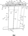
- Figure 2 illustrates an example of an airfoil assembly 60 from the turbine section 28 of the engine 20 (see also Figure 1 ).
- a plurality of the airfoil assemblies 60 are arranged in a circumferential row around the central engine axis A. It is to be understood that although the examples herein are discussed in context of a vane from the turbine section 28, the examples can be applied to other vanes that have support spars.
- the airfoil section 64 is hollow and circumscribes an interior through-cavity 70.
- the airfoil section 64 may have a single through-cavity 70, or the cavity 70 may be sub-divided by one or more ribs.
- the airfoil fairing includes one rib 70a that sub-divides the cavity 70 into forward and aft sub-cavities.
- the airfoil assembly 60 further includes a spar 72 that extends through the through-cavity 70 (e.g., the forward sub-cavity) and mechanically supports the airfoil fairing 62.
- the spar 72 may be formed of a relatively high temperature resistance, high strength material, such as a single crystal metal alloy (e.g., a single crystal nickel- or cobalt-alloy).
- the spar 72 includes a spar platform 72a and a spar leg 72b that extends from the spar platform 72a into the through-cavity 70.
- the spar platform 72a may include attachment features that secure it to a fixed support structure, such as an engine case.
- the spar leg 72b defines an interior through-passage 72c and a spar leg periphery 72d, which is the profile of the outer surface of the spar leg 72b taken at a cross-sectional plane that is parallel to the central engine axis A.
- the spar leg periphery 72d may generally have, but is not limited to, an airfoil shape, a conical shape, an oval shape, or a circular shape.
- the spar leg 72b has a distal end portion that has an attachment 74, such as but not limited to, a pin.
- the end of the spar leg 72b extends past the platform 68 of the airfoil fairing 62 so as to protrude from the fairing 62.
- the support hardware 76, the platform 68 of the airfoil fairing 62, or both may have intermediate structures through which the support hardware 76 interfaces with the platform 68.
- the end of the spar leg 72b extends through the support hardware 76 and is secured with the support hardware 76 (e.g., by the pin) to prevent the spar leg 72b from being retracted back through the support hardware 76.
- the airfoil fairing 62 is thus trapped between the support hardware 76 and the spar platform 72a.
- the airfoil assembly 60 also includes a baffle 73 that extends in the cavity 70 (e.g., the aft sub-cavity).
- the baffle 73 is generally hollow and may include orifices such that cooling air fed to the baffle 73 is distributed through the orifices to impinge onto the inside surfaces of the airfoil section 64 in the cavity 70.
- the baffle 73 defines a baffle periphery 73a and protrudes from the platform 66 where it is fed the cooling air.
- the baffle 73 may be excluded in some implementations.
- the platform 66 has a "box" structure 77.
- the box structure 77 includes a first or inner wall 77a and a second or outer wall 77b that is radially spaced from the first wall 77a to define a plenum 78 there between.
- the plenum 78 may open to the cavity 70 in the airfoil section 64 but may alternatively be isolated from the cavity 70 by one or more seals.
- the walls 77a/77b are joined at forward and trailing ends by end walls 77c/77d. Sides 77e/77f are open such that the platform 66 is open-sided. It is to be understood that the platform 68 may have a similar box structure or a single-wall structure.
- the box structure 77 is formed by at least one continuous fiber ply, represented at 79.
- the fiber ply or plies 79 extend through the airfoil section 64 and then turn outwardly to form the wall 77a of the box structure 77.
- the fiber ply or plies 79 then turn radially outwardly to form the end walls 77c/77d. From the end walls 77c/77d the ply or plies 79 turn back toward the airfoil section 64 to form the wall 77b.
- Openings 77g/77h are formed in the wall 77b for, respectively, the spar leg 72b and the baffle 73, although in implementations where the baffle 73 is excluded the wall 77b will include only the opening 77g for the spar leg 72b.
- the periphery of the opening 77g is a complement to the spar leg periphery 72d of the spar leg 72b
- the periphery of the opening 77h is a complement to the baffle periphery 73a.
- the term "complement" or variations thereof refers to an opening (e.g., the openings 77g/77h) that has a shape that fully or substantially fully tracks the shape of a periphery of a mating component (e.g., the spar leg periphery 72d or the baffle periphery 73a) such that the spar leg 72b and baffle 73 fit closely with the corresponding openings 77g/77h through which they extend.
- Cooling air such as bleed air from the compressor section 24, is conveyed into and through the through-passage 72c of the spar leg 72b. This cooling air is destined for a downstream cooling location, such as a tangential onboard injector (TOBI). Cooling air is also provided into the baffle 73 for impingement cooling of the airfoil fairing 62 in the cavity 70. Seals may be provided in the cavity 70 for isolating the aft sub-cavity from the plenum 78.
- TOBI tangential onboard injector
- Cooling air is also be provided into the region of the cavity 70 between the wall of the airfoil fairing 62 and the spar leg 72b (e.g., to cool the region of the leading edge 64a and fillets between the airfoil section 64 and platforms 66/68).
- the cooling air provided to the through-passage 72c of the spar leg 72b and to the baffle 73 may be at a different pressure than the cooling air provided to the region in the cavity 70 between the wall of the airfoil fairing 62 and the spar leg 72b.
- Figure 3A illustrates a view of the seal plate 80 without the airfoil fairing 62
- Figure 3B illustrates the seal plate 80 and outer portion of the airfoil fairing 62 without the spar 72.
- the seal plate 80 is generally a sheet structure of substantially uniform thickness that defines a first and second openings 82a/82b.
- the seal plate 80 is comprised of first and second plate pieces 80a/80b.
- the plate pieces 80a/80b may be formed of a metallic alloy, such as a nickel- or cobalt-based superalloy.
- the plate pieces 80a/80b are substantially similar in shape and size and are spaced apart, with the wall 77b of the fairing platform 66 sandwiched there between (see Fig. 3A ).
- the seal plate 80 is secured to the platform 66 via one or more fasteners 84.
- the fasteners 84 are spaced around the openings 80a/80b.
- the fasteners 84 may be, but are not limited to, rivets or bolts. As will be described in more detail later below, the fasteners 84 extend through the seal plate 80 and the wall 77b of the platform 66.
- the first opening 82a defines a first opening periphery 82a-1 that is complementary to the spar leg periphery 72d.
- the second opening 82b defines a second opening periphery 82b-1 that is complementary to the baffle periphery 73a.
- the seal plate 80 will only have the opening 82a.
- the seals 86a/86b are between, respectively, the seal plate 80 and the spar leg 72b and the seal plate 80 and the baffle 73.
- the seals 86a/86b seal around the spar leg periphery 72d and the baffle periphery 73 a.
- the seals 86a/86b may be crush seals or weldments, for example.
- the seal 86a around the spar leg 72b is a crush seal, such as a rope seal
- the seal 86b around the baffle 73 is a weldment.
- a "crush seal” is a seal that is deformed by compression in a sealing space.
- the seal 86a may be a weldment and the seal 86b may be a crush seal, or both seals 86a/86b may be crush seals.
- both seals 86a/86b may be weldments if thermal expansion differences can be tolerated without compromising the sealing integrity, although access for welding may be limited by the tight space between the spar platform 72a and the wall 77b of the platform 66.
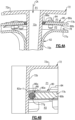
- Figure 4A shows a sectioned view through the airfoil fairing 62, the spar 72, the seal plate 80, and the seal 86a around the spar leg 72b
- Figure 4B shows a closer view of the region of the seal 86a.
- the plate pieces 80a/80b sandwich the wall 77b of the platform 66.
- the edge of the wall 77b of the platform 66 is offset from the edges of the first opening 82a in the seal plate 80 to thereby form a channel 88 around the first opening periphery 82a-1.
- the seal 86a which is a rope seal in this example, is retained in the channel 88 and against the spar leg 72b to seal there with.
- the seal 86a isolates the region indicated at P1 from the region indicated at P2 such that cooling air CA does not leak from P1 to P2, or vice versa depending on the pressures.
- Figure 5 shows a sectioned view through the airfoil fairing 62, the baffle 73, the seal plate 80, and the seal 86b around the baffle 73.
- the plate pieces 80a/80b sandwich the wall 77b of the platform 66. At least the edge of the plate piece 80a is welded to the baffle 73 to form the seal 86b.
- the plate piece 80b may also be welded, however, since the weld location is inside the plenum 78, access for welding may be limited.
- the seal 86b also isolates the region indicated at P1 from the region indicated at P2 such that cooling air CA does not leak from P1 to P2, or vice versa depending on the pressures.
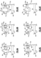
- FIGs 6A to 6F illustrate example configurations of the fasteners 84.
- the examples are shown with respect to sealing with the spar leg 72b, however, it is to be understood that the examples also apply to sealing with the baffle 73.
- the wall 77b of the platform 66 includes a hole 90 and the seal plate 80 includes a hole 92 that is aligned with the hole 90.
- the fastener 84 is received through the holes 90/92 to secure the seal plate 80 to the wall 77b.
- the fastener 84 is a bolt.
- the nut of the bolt may be welded to the shank of the bolt, to facilitate the prevention of loosening.
- the plate piece 80a is welded to the spar leg 72b to form the seal 86a (i.e., a weldment).
- the configuration here is a "baseline" example of a simple joint in which the hole 92 is substantially the same diameter as the hole 90 and the fastener 84 clamps the plate pieces 80a/80b around the wall 77b.
- the plate pieces 80a/80b in this and the following examples are relatively ductile (as compared to CMC) and thus facilitate removal of compressive load that the fastener 84 applies to the stack, reduction in stress on the CMC wall 77b, and maintaining fastener tension even after some extent of creep via the elasticity of the plate pieces 80a/80b.
- the hole 90 in the wall 77b is of larger diameter than the hole 92 in the seal plate 80.
- each of the plate pieces 80a/80b includes a dimple 94 that extends into the hole 90.
- the fastener 84 clamps the dimples 94 together such that the wall 77b is trapped between the plate pieces 80a/80b adjacent to the dimples 94.
- the fastener 84 does not directly compress the wall 77b, as the bolt tension is applied at the dimples 94 without the wall 77b locally there between.
- Such a configuration may facilitate reducing stresses on the wall 77b in comparison to the direct clamping as in Figure 6A and mitigating thermal growth mismatch and tolerances associated with the CMC of the wall 77b.
- Figure 6B The configuration of Figure 6B is a combination of the examples of Figures 6A and 6B .
- the plate piece 80b has a dimple 94, while the plate piece 80a is flat.
- the plate piece 80b may be flat and the plate piece 80a may have the dimple 94, as shown in Figure 6D .
- the fastener 84 in Figures 6C and 6D does not directly compress the wall 77b, as the bolt tension is applied at the dimple 94 without the wall 77b locally there between.
- These configurations may also facilitate reducing stresses on the wall 77b in comparison to the direct clamping as in Figure 6A .
- the plate pieces each include an upstanding boss 96 that extends over the hole 90 in the wall 77b.
- the bosses 96 serve as springs to apply an additional pre-load on the wall 77b that may facilitate taking up differences in thermal expansion between the seal plate 80 and the wall 77b to thereby maintain compression on the wall 77b.
- the pre-load provided by the bosses 96 may also serve to keep the locally adjacent regions of the plate pieces 80a/80b from tending to lift away from the wall 77b due to "levering" from the fastener 84.
- Figure 6F is similar to that of Figure 6A except that the seal plate 80 excludes the plate piece 80b and has only the single plate piece 80a.
- Such a configuration has a relatively less complex assembly, as it eliminates the installation of the plate piece 80b.
Landscapes
- Engineering & Computer Science (AREA)
- Mechanical Engineering (AREA)
- General Engineering & Computer Science (AREA)
- Chemical & Material Sciences (AREA)
- Combustion & Propulsion (AREA)
- Materials Engineering (AREA)
- Architecture (AREA)
- Composite Materials (AREA)
- Physics & Mathematics (AREA)
- Fluid Mechanics (AREA)
- Turbine Rotor Nozzle Sealing (AREA)
Applications Claiming Priority (2)
| Application Number | Priority Date | Filing Date | Title |
|---|---|---|---|
| US17/307,074 US11549385B2 (en) | 2021-05-04 | 2021-05-04 | Airfoil assembly with seal plate and seal |
| EP22170259.0A EP4086431B1 (de) | 2021-05-04 | 2022-04-27 | Schaufelprofilanordnung mit dichtungsplatte und dichtung |
Related Parent Applications (2)
| Application Number | Title | Priority Date | Filing Date |
|---|---|---|---|
| EP22170259.0A Division EP4086431B1 (de) | 2021-05-04 | 2022-04-27 | Schaufelprofilanordnung mit dichtungsplatte und dichtung |
| EP22170259.0A Division-Into EP4086431B1 (de) | 2021-05-04 | 2022-04-27 | Schaufelprofilanordnung mit dichtungsplatte und dichtung |
Publications (3)
| Publication Number | Publication Date |
|---|---|
| EP4286655A2 true EP4286655A2 (de) | 2023-12-06 |
| EP4286655A3 EP4286655A3 (de) | 2024-02-28 |
| EP4286655B1 EP4286655B1 (de) | 2026-03-25 |
Family
ID=81389193
Family Applications (2)
| Application Number | Title | Priority Date | Filing Date |
|---|---|---|---|
| EP23204996.5A Active EP4286655B1 (de) | 2021-05-04 | 2022-04-27 | Schaufelanordnung mit dichtungsplatte und dichtung |
| EP22170259.0A Active EP4086431B1 (de) | 2021-05-04 | 2022-04-27 | Schaufelprofilanordnung mit dichtungsplatte und dichtung |
Family Applications After (1)
| Application Number | Title | Priority Date | Filing Date |
|---|---|---|---|
| EP22170259.0A Active EP4086431B1 (de) | 2021-05-04 | 2022-04-27 | Schaufelprofilanordnung mit dichtungsplatte und dichtung |
Country Status (2)
| Country | Link |
|---|---|
| US (1) | US11549385B2 (de) |
| EP (2) | EP4286655B1 (de) |
Families Citing this family (1)
| Publication number | Priority date | Publication date | Assignee | Title |
|---|---|---|---|---|
| FR3161921A1 (fr) * | 2024-05-02 | 2025-11-07 | Safran Aircraft Engines | Aubage metallique pour une turbomachine d’aeronef et son procede de fabrication |
Family Cites Families (16)
| Publication number | Priority date | Publication date | Assignee | Title |
|---|---|---|---|---|
| US6464456B2 (en) * | 2001-03-07 | 2002-10-15 | General Electric Company | Turbine vane assembly including a low ductility vane |
| US7452189B2 (en) | 2006-05-03 | 2008-11-18 | United Technologies Corporation | Ceramic matrix composite turbine engine vane |
| US9335051B2 (en) | 2011-07-13 | 2016-05-10 | United Technologies Corporation | Ceramic matrix composite combustor vane ring assembly |
| CA2901835A1 (en) | 2013-03-04 | 2014-10-02 | Rolls-Royce North American Technologies, Inc. | Compartmentalization of cooling air flow in a structure comprising a cmc component |
| CN105378226B (zh) | 2013-07-19 | 2017-11-10 | 通用电气公司 | 带有冲击挡板的涡轮喷嘴 |
| WO2015041794A1 (en) | 2013-09-17 | 2015-03-26 | United Technologies Corporation | Airfoil assembly formed of high temperature-resistant material |
| US9970317B2 (en) * | 2014-10-31 | 2018-05-15 | Rolls-Royce North America Technologies Inc. | Vane assembly for a gas turbine engine |
| US10655482B2 (en) * | 2015-02-05 | 2020-05-19 | Rolls-Royce Corporation | Vane assemblies for gas turbine engines |
| US10329950B2 (en) * | 2015-03-23 | 2019-06-25 | Rolls-Royce North American Technologies Inc. | Nozzle guide vane with composite heat shield |
| US10774665B2 (en) * | 2018-07-31 | 2020-09-15 | General Electric Company | Vertically oriented seal system for gas turbine vanes |
| US10767497B2 (en) * | 2018-09-07 | 2020-09-08 | Rolls-Royce Corporation | Turbine vane assembly with ceramic matrix composite components |
| US11149568B2 (en) | 2018-12-20 | 2021-10-19 | Rolls-Royce Plc | Sliding ceramic matrix composite vane assembly for gas turbine engines |
| US11008880B2 (en) | 2019-04-23 | 2021-05-18 | Rolls-Royce Plc | Turbine section assembly with ceramic matrix composite vane |
| US11156105B2 (en) | 2019-11-08 | 2021-10-26 | Raytheon Technologies Corporation | Vane with seal |
| US11415006B2 (en) | 2020-09-17 | 2022-08-16 | Raytheon Technologies Corporation | CMC vane with support spar and baffle |
| US11506069B2 (en) * | 2021-03-03 | 2022-11-22 | Raytheon Technologies Corporation | Vane arc segment with spring seal |
-
2021
- 2021-05-04 US US17/307,074 patent/US11549385B2/en active Active
-
2022
- 2022-04-27 EP EP23204996.5A patent/EP4286655B1/de active Active
- 2022-04-27 EP EP22170259.0A patent/EP4086431B1/de active Active
Also Published As
| Publication number | Publication date |
|---|---|
| US20220356808A1 (en) | 2022-11-10 |
| EP4086431A1 (de) | 2022-11-09 |
| EP4086431B1 (de) | 2024-01-03 |
| EP4286655A3 (de) | 2024-02-28 |
| EP4286655B1 (de) | 2026-03-25 |
| US11549385B2 (en) | 2023-01-10 |
Similar Documents
| Publication | Publication Date | Title |
|---|---|---|
| US11047245B2 (en) | CMC component attachment pin | |
| US11255209B2 (en) | CMC BOAS arrangement | |
| US11035243B2 (en) | Seal assembly for gas turbine engines | |
| US11415006B2 (en) | CMC vane with support spar and baffle | |
| WO2014134536A1 (en) | Method and apparatus for selectively collecting pre-diffuser airflow | |
| US12025020B2 (en) | Vane system with continuous support ring | |
| US11125093B2 (en) | Vane with L-shaped seal | |
| EP4030036A1 (de) | Leitschaufelbogensegment-trägerplattform mit gekrümmtem radialem kanal | |
| EP4086431B1 (de) | Schaufelprofilanordnung mit dichtungsplatte und dichtung | |
| EP4063618B1 (de) | Leitschaufelbogensegment mit federdichtung | |
| EP4015773B1 (de) | Schaufel mit leitblech und eingelassenem holm | |
| EP4053379B1 (de) | Schaufelbogensegment mit holm und stiftverkleidung | |
| US11781432B2 (en) | Nested vane arrangement for gas turbine engine | |
| US20180080335A1 (en) | Gas turbine engine sealing arrangement | |
| US20240183276A1 (en) | Airfoil assembly with fiber-reinforced composite rings | |
| US11603770B2 (en) | Vane assembly with integrated nozzle tube | |
| US11092015B2 (en) | Airfoil with metallic shield |
Legal Events
| Date | Code | Title | Description |
|---|---|---|---|
| PUAI | Public reference made under article 153(3) epc to a published international application that has entered the european phase |
Free format text: ORIGINAL CODE: 0009012 |
|
| STAA | Information on the status of an ep patent application or granted ep patent |
Free format text: STATUS: THE APPLICATION HAS BEEN PUBLISHED |
|
| AC | Divisional application: reference to earlier application |
Ref document number: 4086431 Country of ref document: EP Kind code of ref document: P |
|
| AK | Designated contracting states |
Kind code of ref document: A2 Designated state(s): AL AT BE BG CH CY CZ DE DK EE ES FI FR GB GR HR HU IE IS IT LI LT LU LV MC MK MT NL NO PL PT RO RS SE SI SK SM TR |
|
| REG | Reference to a national code |
Ref legal event code: R079 Ipc: F01D0005140000 Ref country code: DE Ref legal event code: R079 Ref document number: 602022033239 Country of ref document: DE Free format text: PREVIOUS MAIN CLASS: F01D0011000000 Ipc: F01D0005140000 |
|
| PUAL | Search report despatched |
Free format text: ORIGINAL CODE: 0009013 |
|
| AK | Designated contracting states |
Kind code of ref document: A3 Designated state(s): AL AT BE BG CH CY CZ DE DK EE ES FI FR GB GR HR HU IE IS IT LI LT LU LV MC MK MT NL NO PL PT RO RS SE SI SK SM TR |
|
| RIC1 | Information provided on ipc code assigned before grant |
Ipc: F01D 11/00 20060101ALI20240119BHEP Ipc: F01D 9/06 20060101ALI20240119BHEP Ipc: F01D 5/28 20060101ALI20240119BHEP Ipc: F01D 5/14 20060101AFI20240119BHEP |
|
| STAA | Information on the status of an ep patent application or granted ep patent |
Free format text: STATUS: REQUEST FOR EXAMINATION WAS MADE |
|
| 17P | Request for examination filed |
Effective date: 20240809 |
|
| RBV | Designated contracting states (corrected) |
Designated state(s): AL AT BE BG CH CY CZ DE DK EE ES FI FR GB GR HR HU IE IS IT LI LT LU LV MC MK MT NL NO PL PT RO RS SE SI SK SM TR |
|
| GRAP | Despatch of communication of intention to grant a patent |
Free format text: ORIGINAL CODE: EPIDOSNIGR1 |
|
| STAA | Information on the status of an ep patent application or granted ep patent |
Free format text: STATUS: GRANT OF PATENT IS INTENDED |
|
| INTG | Intention to grant announced |
Effective date: 20251031 |
|
| GRAS | Grant fee paid |
Free format text: ORIGINAL CODE: EPIDOSNIGR3 |
|
| GRAA | (expected) grant |
Free format text: ORIGINAL CODE: 0009210 |
|
| STAA | Information on the status of an ep patent application or granted ep patent |
Free format text: STATUS: THE PATENT HAS BEEN GRANTED |
|
| AC | Divisional application: reference to earlier application |
Ref document number: 4086431 Country of ref document: EP Kind code of ref document: P |
|
| AK | Designated contracting states |
Kind code of ref document: B1 Designated state(s): AL AT BE BG CH CY CZ DE DK EE ES FI FR GB GR HR HU IE IS IT LI LT LU LV MC MK MT NL NO PL PT RO RS SE SI SK SM TR |
|
| REG | Reference to a national code |
Ref country code: CH Ref legal event code: F10 Free format text: ST27 STATUS EVENT CODE: U-0-0-F10-F00 (AS PROVIDED BY THE NATIONAL OFFICE) Effective date: 20260325 Ref country code: GB Ref legal event code: FG4D |