EP4286578A1 - Yarn tension control device, knotter device, and flat knitting machine - Google Patents
Yarn tension control device, knotter device, and flat knitting machine Download PDFInfo
- Publication number
- EP4286578A1 EP4286578A1 EP23176866.4A EP23176866A EP4286578A1 EP 4286578 A1 EP4286578 A1 EP 4286578A1 EP 23176866 A EP23176866 A EP 23176866A EP 4286578 A1 EP4286578 A1 EP 4286578A1
- Authority
- EP
- European Patent Office
- Prior art keywords
- yarn
- cam
- arm
- control device
- tension
- Prior art date
- Legal status (The legal status is an assumption and is not a legal conclusion. Google has not performed a legal analysis and makes no representation as to the accuracy of the status listed.)
- Granted
Links
Images





Classifications
-
- D—TEXTILES; PAPER
- D04—BRAIDING; LACE-MAKING; KNITTING; TRIMMINGS; NON-WOVEN FABRICS
- D04B—KNITTING
- D04B15/00—Details of, or auxiliary devices incorporated in, weft knitting machines, restricted to machines of this kind
- D04B15/38—Devices for supplying, feeding, or guiding threads to needles
- D04B15/44—Tensioning devices for individual threads
-
- B—PERFORMING OPERATIONS; TRANSPORTING
- B65—CONVEYING; PACKING; STORING; HANDLING THIN OR FILAMENTARY MATERIAL
- B65H—HANDLING THIN OR FILAMENTARY MATERIAL, e.g. SHEETS, WEBS, CABLES
- B65H59/00—Adjusting or controlling tension in filamentary material, e.g. for preventing snarling; Applications of tension indicators
- B65H59/10—Adjusting or controlling tension in filamentary material, e.g. for preventing snarling; Applications of tension indicators by devices acting on running material and not associated with supply or take-up devices
- B65H59/20—Co-operating surfaces mounted for relative movement
- B65H59/26—Co-operating surfaces mounted for relative movement and arranged to deflect material from straight path
- B65H59/32—Co-operating surfaces mounted for relative movement and arranged to deflect material from straight path the surfaces being urged away from each other
- B65H59/34—Surfaces movable automatically to compensate for variation in tension
-
- D—TEXTILES; PAPER
- D04—BRAIDING; LACE-MAKING; KNITTING; TRIMMINGS; NON-WOVEN FABRICS
- D04B—KNITTING
- D04B15/00—Details of, or auxiliary devices incorporated in, weft knitting machines, restricted to machines of this kind
- D04B15/32—Cam systems or assemblies for operating knitting instruments
Definitions
- the disclosure relates to a technique of a yarn tension control device, and a knotter device and a flat knitting machine including the yarn tension control device.
- Patent Literature 1 discloses a device that is provided in a knotter device and applies a constant tension to a yarn by a biasing force of a spring. Furthermore, it is also known that a device adapted to apply tension to a yarn by a biasing force of a spring is provided in a flat knitting machine.
- Patent Literature 1 since the device disclosed in Patent Literature 1 applies a constant tension to the yarn even in a state other than a yarn knotting operation, there is a problem that a load is applied to the yarn more than necessary. Therefore, a yarn tension applying device capable of controlling the tension applied to the yarn is desired.
- Patent Literature 1 JP 2614775 B2
- the disclosure has been made in view of the above circumstances, and an object of the disclosure is to provide a yarn tension control device, a knotter device, and a flat knitting machine capable of controlling tension applied to a yarn.
- a yarn tension control device includes: a motor that generates a driving force; a cam configured to be rotatable by the driving force of the motor; a pair of yarn guides that guides a yarn to a predetermined position; a spring that generates a biasing force; and an arm that is freely-rocked and supported along a virtual plane passing between the pair of yarn guides, includes an insertion section through which the yarn guided by the pair of yarn guides is inserted and an action section on which the cam can act, is biased by the spring in a direction of applying a tension to the yarn, and rocks in a direction away from the pair of yarn guides with reference to a position where the biasing force of the spring and the tension of the yarn are balanced by an action of the cam on the action section to increase the tension applied to the yarn.
- the tension applied to the yarn can be controlled.
- the arm decreases the tension applied to the yarn by rocking in a direction of approaching the pair of yarn guides with reference to the balanced position by an action of the cam on the action section.
- one end of the spring is fixed to the arm, and the other end of the spring is fixed to the cam.
- the cam includes a first cam configured to be capable of acting on the action section of the arm, and a second cam to which the other end of the spring is fixed, and is configured to be capable of switching between the first cam and the second cam to change which one of the first cam and the second cam is to be rotated by the driving force of the motor.
- the biasing force of the spring can be controlled, and the tension applied to the yarn can be easily increased.
- the cam includes a first cam configured to act on the action section of the arm and a second cam to which the other end of the spring is fixed, one of the first cam and the second cam is fixed to a motor shaft of the motor, and the other one of the first cam and the second cam is connected to the one of the first cam and the second cam with a differential gear interposed between the first cam and the second cam, and is configured to rotate in a direction opposite to the one of the first cam and the second cam along with rotation of the one of the first cam and the second cam.
- the biasing force of the spring can be controlled, and the tension applied to the yarn can be easily increased.
- a knotter device includes the yarn tension control device according to any one of claims 1 to 5.
- the tension applied to the yarn can be changed before, during, and after a yarn knotting operation.
- a flat knitting machine includes the yarn tension control device according to any one of claims 1 to 5.
- the tension applied to the yarn can be controlled.
- directions indicated by arrows U, D, F, B, L, and R in the drawings are defined as an upward direction, a downward direction, a forward direction, a backward direction, a left direction, and a right direction, respectively. Furthermore, in the drawings, illustration of each component is appropriately omitted for simplification of illustration.
- a yarn feeding mechanism 1 is configured to feed a yarn A used for knitting a knitted fabric from a yarn cone 2 to a flat knitting machine 4 through a knotter device 3.
- the knotter device 3 is disposed downstream in a yarn feeding direction of the yarn cone 2
- the flat knitting machine 4 is disposed downstream in the yarn feeding direction of the knotter device 3.
- a yarn feeder 5 moves along a needle bed 7 in conjunction with a carriage 6.
- a large number of knitting needles 8 are arranged in line on the needle bed 7, and the knitting needles 8 advance and retreat to a tooth gap 9 to pull the yarn A from the yarn feeder 5 to knit a knitted fabric product C.
- the knotter device 3 joins the yarn A being used in the flat knitting machine 4 and a new yarn A wound around the yarn cone 2.
- the knotter device 3 includes a yarn selecting section 10 and a yarn joining section 20.
- the yarn tension control device 30 controls a tension of the yarn A when carrying out a yarn knotting operation.
- the yarn tension control device 30 includes a motor 31, a motor base 32, the cam 33, a yarn guide 37, the arm 38, and a kick spring 39.
- the motor 31 generates a driving force.
- any motor can be used, but a stepping motor and a servo motor are suitable.
- the motor 31 includes a motor shaft 31a rotatable by the generated driving force.
- the motor 31 is disposed with an axial direction of the motor shaft 31a oriented in a vertical direction, and is provided so that a rotation amount and a rotation direction of the motor shaft 31a can be adjusted by a control unit (not illustrated).
- the motor base 32 supports the motor 31.
- the motor base 32 is formed in an appropriate shape capable of supporting the motor 31, and is provided below the motor 31 so as to pass through the motor shaft 31a.
- the motor base 32 is provided with a pin 32a.
- the pin 32a is provided to extend downward from a lower surface of the motor base 32 in the vicinity of a portion through which the motor shaft 31a is inserted. An end portion of the kick spring 39 described later is engaged with the pin 32a.
- the first protrusion 35 is a protrusion on one side of the two protrusions constituting the substantially L-shape of the cam 33, and acts on a pin 38b of the arm 38 described later when the cam 33 rotates in a clockwise direction in the bottom view.
- the first protrusion 35 is formed to extend substantially rightward from a portion through which the motor shaft 31a is inserted to a position where the first protrusion can act on the pin 38b.
- a first pressing surface 35a facing the pin 38b is formed on the first protrusion 35, and presses the pin 38b on the first pressing surface 35a when the cam 33 rotates in the clockwise direction in the bottom view.
- the second protrusion 36 is a protrusion on the other side of the two protrusions constituting the substantially L-shape of the cam 33, and acts on the pin 38b of the arm 38 described later when the cam 33 rotates in a counterclockwise direction in the bottom view.
- the second protrusion 36 is formed so as to extend substantially rearward from the portion through which the motor shaft 31a is inserted to a position where the second protrusion can act on the pin 38b.
- the second protrusion 36 is formed so as to extend in a direction substantially perpendicular to the first protrusion 35.
- a second pressing surface 36a facing the pin 38b is formed on the second protrusion 36, and presses the pin 38b on the second pressing surface 36a when the cam 33 rotates in the counterclockwise direction in the bottom view.
- the yarn guide 37 is adapted to guide the yarn A to a predetermined position.
- the yarn guide 37 extends from the motor base 32 to the side (back side in the present embodiment) of the motor base 32.
- a pair of the yarn guides 37 are disposed vertically.
- the yarn guide 37 on an upper side may be referred to as a yarn guide 37A
- the yarn guide 37 on a lower side may be referred to as a yarn guide 37B.
- an insertion hole 37a is formed at a distal end of the yarn guide 37, and the yarn A fed from the yarn cone 2 is inserted into the insertion hole 37a.
- the insertion hole 37a of the yarn guide 37A and the insertion hole 37a of the yarn guide 37B are formed at overlapping positions in the bottom view.
- the arm 38 is adapted to change the tension applied to the yarn A guided by the yarn guide 37.
- the arm 38 is a rigid body having a longitudinal rod shape and a plate shape, and is disposed with a plate surface facing the vertical direction.
- the arm 38 is inserted into and fixed to the motor shaft 31a, and is provided to rock around the axis of the motor shaft 31a.
- the arm 38 is disposed between the motor base 32 and the cam 33 and between the yarn guide 37A and the yarn guide 37B in the vertical direction, and is freely-rocked and supported along a virtual plane passing between the yarn guide 37A and the yarn guide 37B.
- the virtual plane is a plane that intersects with a line segment connecting the insertion hole 37a of the yarn guide 37A and the insertion hole 37a of the yarn guide 37B, and is a horizontal plane in the present embodiment.
- the arm 38 includes an insertion hole 38a and the pin 38b.
- the insertion hole 38a illustrated in FIG. 4 is formed so as to vertically penetrate a distal end of the arm 38, and the yarn A guided by the yarn guide 37 is inserted through the insertion hole.
- the insertion hole 38a is formed at a position where a distance in the plan view from an axial center of the motor shaft 31a to a center of the insertion hole 38a is the same as a distance in the plan view from the axial center of the motor shaft 31a to a center of the insertion hole 37a of the yarn guide 37.
- the insertion hole 38a is formed at a position where the center of the insertion hole 38a can coincide with the center of the insertion hole 37a of the yarn guide 37 when the arm 38 is rocked.
- the kick spring 39 biases the arm 38.
- the kick spring 39 is provided between the motor base 32 and the arm 38 such that the motor shaft 31a is inserted through a center portion of the kick spring 39.
- One end of the kick spring 39 is fixed to the arm 38, and the other end of the kick spring 39 is fixed to the pin 32a of the motor base 32.
- the kick spring 39 thus disposed biases the arm 38 in a direction of applying a tension to the yarn A, more specifically, in a direction in which the arm 38 rocks counterclockwise in the bottom view.
- FIG. 4 illustrates a state in which the biasing force of the kick spring 39 applied to the arm 38 and the tension of the yarn A are balanced.
- the motor 31 is driven to rotate the cam 33 in the counterclockwise direction in the bottom view from the position illustrated in FIG. 3 , and the cam 33 is moved to the position where neither the first protrusion 35 nor the second protrusion 36 abuts on the pin 38b of the arm 38. Then, the cam 33 does not act on the arm 38, and only the biasing force of the kick spring 39 is applied to the arm. At this time, the arm 38 rocks by a predetermined angle in the counterclockwise direction in the bottom view from the first position illustrated in FIG. 3 by the biasing force of the kick spring 39. Thus, the portion of the yarn A inserted through the insertion hole 38a of the arm 38 is pulled by the arm 38.
- the slack of the yarn A generated during the yarn knotting operation can be removed by the tension of the kick spring 39 applied to the yarn A during the yarn knotting operation.
- the position of the arm 38 illustrated in FIG. 4 is referred to as a "second position".
- the motor 31 is driven to rotate the cam 33 in the counterclockwise direction in the bottom view from the position illustrated in FIG. 4 to bring the second pressing surface 36a of the second protrusion 36 into contact with the pin 38b of the arm 38.
- the cam 33 is further rotated in the counterclockwise direction in the bottom view, the second protrusion 36 presses the pin 38b of the arm 38, and rocks the arm 38 further from the second position illustrated in FIG. 4 in the counterclockwise direction in the bottom view, that is, in a direction in which the distal end portion of the arm 38 is separated from the insertion hole 37a of the yarn guides 37A and 37B in the plan view.
- the yarn A is forcibly pulled by the arm 38.
- the knot of the yarn A can be tightened by forcibly pulling the yarn A at the end of the yarn knotting operation.
- the position of the arm 38 illustrated in FIG. 5 is referred to as a "third position".
- the yarn tension control device 30 can change the tension applied to the yarn A according to each scene of the yarn knotting operation. Therefore, while reducing the load applied to the yarn A when the yarn knotting operation is not carried out, the slack of the yarn A can be removed or the knot of the yarn A can be strengthened when the yarn knotting operation is carried out. Furthermore, since the arm 38 is formed of a rigid body, it is possible to perform control with excellent responsiveness.
- the cam 33 causes the arm 38 to rock in the clockwise direction in the bottom view and in the counterclockwise direction in the bottom view by the two protrusions of the first protrusion 35 and the second protrusion 36, but may cause the arm 38 to rock in the clockwise direction in the bottom view and in the counterclockwise direction in the bottom view by one protrusion. That is, the cam 33 does not necessarily have to include two protrusions, and may include one protrusion.
- the cam 33 can be rotated so that the biasing force of the kick spring 39 decreases.
- the cam 33 can be rotated so that the biasing force of the kick spring 39 increases.
- a cam 33B illustrated in FIG. 6B can be configured.
- FIG. 6B illustrates the cam 33B which is a second different example of the cam 33, and illustrates a state in which the biasing force of the kick spring 39 applied to the arm 38 and the tension of the yarn A are balanced.
- the cam 33B illustrated in FIG. 6B is different from the cam 33 illustrated in FIGS. 2 to 5 in that a third protrusion 46 is provided.
- the other end of the kick spring 39 is fixed to the first protrusion 35.
- the third protrusion 46 is formed between the first protrusion 35 and the pin 38b of the arm 38 so as to extend substantially rightward from a portion through which the motor shaft 31a is inserted.
- a third pressing surface 46a facing the pin 38b is formed on the third protrusion 46.
- the third pressing surface 46a is formed at a position closer to the pin 38b than the first pressing surface 35a of the first protrusion 35.
- a sensor that measures the tension applied to the yarn A may be disposed, and the position of the arm 38 may be adjusted based on a measurement value of the sensor.
- the tension applied to the yarn A can be controlled to a desired value.
- a motor capable of acquiring shaft torque may be used as the motor 31, and the position of the arm 38 may be adjusted on the basis of a value of the shaft torque acquired by the motor 31.
- the tension applied to the yarn A can be controlled to a desired value.
- the shaft torque acquired by the motor 31 includes not only the tension applied to the yarn A but also the biasing force of the kick spring 39. Therefore, it is preferable to provide a sensor that detects the position of the arm 38 so that a position of an end point of the kick spring 39 can be grasped by the sensor.
- the tension to be applied to the yarn A can be calculated by subtracting the biasing force of the kick spring 39 from the shaft torque acquired by the motor 31.
- the lifting and lowering member 41a is formed in a hollow shape with one end opened, and is provided so as to enclose the motor shaft 31a.
- the cross-sectional shape of the opening portion of the lifting and lowering member 41a is similar to, but not limited to, the cross-sectional shape of the motor shaft 31a, for example, and the lifting and lowering member 41a is rotatable together with the motor shaft 31a and is provided to be vertically movable by a solenoid (not illustrated) provided below the lifting and lowering member 41a.
- a lower end of the lifting and lowering member 41a is formed in a shape capable of meshing with the first cam 53 and the second cam 56.
- the first cam 53 is for rocking the arm 38, and is inserted into the lower end of the lifting and lowering member 41a.
- the first cam 53 is formed in a plate shape, and is disposed with a plate surface facing the vertical direction.
- a protrusion 55 is formed on the first cam 53.
- the protrusion 58 extends substantially rightward from a portion through which the lifting and lowering member 41a is inserted.
- the other end of the kick spring 39 is fixed to the protrusion 58.
- the lifting and lowering member 41a is provided so as to be vertically movable between a position at which its lower end meshes with the first cam 53 illustrated in FIG. 8A and a position at which its lower end meshes with the second cam 56 illustrated in FIG. 8B .
- the first cam 53 can be rotated by driving the motor 31.
- the second cam 56 can be rotated by driving the motor 31.
- the first cam 53 and the second cam 56 are configured to be capable of switching between the first cam 53 and the second cam 56 to change which one of the first cam 53 and the second cam 56 is to be rotated by the driving force of the motor 31.
- the motor 31 is driven while the lifting and lowering member 41a is moved to the position illustrated in FIG. 8A , so that the first cam 53 is rotated in the clockwise direction in the bottom view and the pin 38b of the arm 38 is pressed by the first pressing surface 55a.
- the arm 38 can be rocked to the first position illustrated in FIG. 3 .
- the first cam 53 is rotated in the counterclockwise direction in the bottom view to a position where the protrusion 55 does not abut on the pin 38b of the arm 38.
- the arm 38 is rocked to the second position illustrated in FIG. 4 in the counterclockwise direction in the bottom view by the biasing force of the kick spring 39, so that a portion of the yarn A inserted into the insertion hole 38a of the arm 38 is pulled by the arm 38.
- the slack of the yarn A generated during the yarn knotting operation can be removed.
- the second cam 56 can be rotated by driving the motor 31 in a state where the lifting and lowering member 41a is moved to the position illustrated in FIG. 8B .
- the biasing force of the kick spring 39 applied to the arm 38 can be changed, and eventually, the tension applied to the yarn A can be controlled when removing the slack of the yarn A.
- the biasing force of the kick spring 39 can be made variable, and the forcible tension application to the yarn A by the pulling of the arm 38 can be independently carried out, so that both can be achieved.
- the motor 31 is driven in a state where the lifting and lowering member 41a is moved to the position illustrated in FIG. 8A , and the first cam 53 is rotated in the counterclockwise direction in the bottom view, whereby the protrusion 55 presses the pin 38b of the arm 38.
- the arm 38 can be rocked to the third position illustrated in FIG. 5 , and eventually, the knot of the yarn A can be tightened.
- the first cam 63 is for rocking an arm 38, and is formed in the same shape as the first cam 53 of the second embodiment.
- a pressing surface 65a is formed on a protrusion 65 of the first cam 63, and presses a pin 38b on the pressing surface 65a when the first cam 63 rotates in the counterclockwise direction in the bottom view.
- the second cam 66 is for controlling the biasing force of a kick spring 39, and is formed in the same shape as the second cam 56 of the second embodiment.
- the second cam 66 is fixed to a motor shaft 31a and is provided to rotate about the axis of the motor shaft 31a as the motor shaft 31a rotates.
- the other end of the kick spring 39 is fixed to a protrusion 68 of the second cam 66.
- the tension becomes small at the time of reversing a yarn feeder at a knitted fabric end on a side far from a yarn tension control device provided in the vicinity of a side surface of the flat knitting machine.
- the tension application by spring biasing cannot follow a change in tension of the yarn, and there is a problem that the crossover of the inlay yarn at the time of reversal becomes long at the knitted fabric end on the far side.
Landscapes
- Engineering & Computer Science (AREA)
- Textile Engineering (AREA)
- Knitting Machines (AREA)
- Sewing Machines And Sewing (AREA)
- Tension Adjustment In Filamentary Materials (AREA)
Abstract
Description
- The disclosure relates to a technique of a yarn tension control device, and a knotter device and a flat knitting machine including the yarn tension control device.
- Conventionally, a device for applying tension to a yarn fed to a textile machine by a biasing force of a spring is known. For example, Patent Literature 1 discloses a device that is provided in a knotter device and applies a constant tension to a yarn by a biasing force of a spring. Furthermore, it is also known that a device adapted to apply tension to a yarn by a biasing force of a spring is provided in a flat knitting machine.
- However, since the device disclosed in Patent Literature 1 applies a constant tension to the yarn even in a state other than a yarn knotting operation, there is a problem that a load is applied to the yarn more than necessary. Therefore, a yarn tension applying device capable of controlling the tension applied to the yarn is desired.
- Patent Literature 1:
JP 2614775 B2 - The disclosure has been made in view of the above circumstances, and an object of the disclosure is to provide a yarn tension control device, a knotter device, and a flat knitting machine capable of controlling tension applied to a yarn.
- The problem to be solved by the disclosure is as described above, and means for solving the problem will be described below.
- In other words, a yarn tension control device according to the disclosure includes: a motor that generates a driving force; a cam configured to be rotatable by the driving force of the motor; a pair of yarn guides that guides a yarn to a predetermined position; a spring that generates a biasing force; and an arm that is freely-rocked and supported along a virtual plane passing between the pair of yarn guides, includes an insertion section through which the yarn guided by the pair of yarn guides is inserted and an action section on which the cam can act, is biased by the spring in a direction of applying a tension to the yarn, and rocks in a direction away from the pair of yarn guides with reference to a position where the biasing force of the spring and the tension of the yarn are balanced by an action of the cam on the action section to increase the tension applied to the yarn.
- With such a configuration, the tension applied to the yarn can be controlled.
- Furthermore, the arm decreases the tension applied to the yarn by rocking in a direction of approaching the pair of yarn guides with reference to the balanced position by an action of the cam on the action section.
- With such a configuration, the tension applied to the yarn can be more finely controlled.
- Furthermore, one end of the spring is fixed to the arm, and the other end of the spring is fixed to the cam.
- With this configuration, the biasing force of the spring can be controlled.
- Furthermore, the cam includes a first cam configured to be capable of acting on the action section of the arm, and a second cam to which the other end of the spring is fixed, and is configured to be capable of switching between the first cam and the second cam to change which one of the first cam and the second cam is to be rotated by the driving force of the motor.
- With such a configuration, the biasing force of the spring can be controlled, and the tension applied to the yarn can be easily increased.
- Furthermore, the cam includes a first cam configured to act on the action section of the arm and a second cam to which the other end of the spring is fixed, one of the first cam and the second cam is fixed to a motor shaft of the motor, and the other one of the first cam and the second cam is connected to the one of the first cam and the second cam with a differential gear interposed between the first cam and the second cam, and is configured to rotate in a direction opposite to the one of the first cam and the second cam along with rotation of the one of the first cam and the second cam.
- With such a configuration, the biasing force of the spring can be controlled, and the tension applied to the yarn can be easily increased.
- Furthermore, a knotter device includes the yarn tension control device according to any one of claims 1 to 5.
- With such a configuration, the tension applied to the yarn can be changed before, during, and after a yarn knotting operation.
- Furthermore, a flat knitting machine includes the yarn tension control device according to any one of claims 1 to 5.
- With such a configuration, the crossover of the yarn at the time of weft yarn inversion at a knitted fabric end can be suppressed from becoming long.
- As an effect of the disclosure, the tension applied to the yarn can be controlled.
-
-
FIG. 1 is a schematic diagram illustrating an example of a yarn feeding mechanism to which a yarn tension control device according to a first embodiment of the disclosure is applied; -
FIG. 2 is a perspective view of the yarn tension control device of the same; -
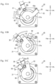
FIG. 3 is a bottom view of the yarn tension control device of the same before a yarn knotting operation; -
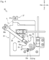
FIG. 4 is a bottom view of the yarn tension control device of the same during the yarn knotting operation; -
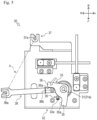
FIG. 5 is a bottom view of the yarn tension control device of the same at the end of the yarn knotting operation; -
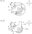
FIG. 6A is a bottom view of a cam and the like of a first different example;FIG. 6B is a bottom view of a cam and the like of a second different example; -
FIG. 7 is a perspective view of a yarn tension control device according to a second embodiment; -
FIG. 8A is also a side sectional view illustrating a state in which a first cam and a motor shaft are meshed with each other;FIG. 8B is a side sectional view illustrating a state in which a second cam and the motor shaft are meshed with each other; -
FIG. 9A is a bottom view of the yarn tension control device of the same before the yarn knotting operation;FIG. 9B is a bottom view of the yarn tension control device during the yarn knotting operation;FIG. 9C is a bottom view of the yarn tension control device at the end of the yarn knotting operation; -
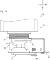
FIG. 10 is a front view of a yarn tension control device according to a third embodiment; -
FIG. 11A is a bottom view of the yarn tension control device of the same during the yarn knotting operation;FIG. 11B is a bottom view of the yarn tension control device at the end of the yarn knotting operation;FIG. 11C is a bottom view of the yarn tension control device before the yarn knotting operation; and -
FIG. 12 is a schematic diagram illustrating an example of a yarn feeding mechanism in a case where a yarn tension control device is applied to a flat knitting machine. - In the following description, directions indicated by arrows U, D, F, B, L, and R in the drawings are defined as an upward direction, a downward direction, a forward direction, a backward direction, a left direction, and a right direction, respectively. Furthermore, in the drawings, illustration of each component is appropriately omitted for simplification of illustration.
- As illustrated in
FIG. 1 , a yarn feeding mechanism 1 is configured to feed a yarn A used for knitting a knitted fabric from ayarn cone 2 to a flat knitting machine 4 through aknotter device 3. In the yarn feeding mechanism 1, theknotter device 3 is disposed downstream in a yarn feeding direction of theyarn cone 2, and the flat knitting machine 4 is disposed downstream in the yarn feeding direction of theknotter device 3. - In the flat knitting machine 4, a
yarn feeder 5 moves along aneedle bed 7 in conjunction with acarriage 6. A large number ofknitting needles 8 are arranged in line on theneedle bed 7, and theknitting needles 8 advance and retreat to atooth gap 9 to pull the yarn A from theyarn feeder 5 to knit a knitted fabric product C. - The
knotter device 3 joins the yarn A being used in the flat knitting machine 4 and a new yarn A wound around theyarn cone 2. Theknotter device 3 includes ayarn selecting section 10 and ayarn joining section 20. - The
yarn selecting section 10 is configured to guide the yarn A selected from a plurality of the yarns A fed from theyarn cone 2 to theyarn joining section 20. Theyarn joining section 20 is configured to join the yarn A selected by theyarn selecting section 10 and the yarn A being used in the flat knitting machine 4. Theyarn joining section 20 is disposed downstream in the yarn feeding direction of theyarn selecting section 10. Theyarn joining section 20 includes a yarntension control device 30. - Hereinafter, a configuration of the yarn
tension control device 30 will be described with reference toFIGS. 2 and4 . Note that acam 33 and anarm 38 are rotatable or capable of rocked members, and the description will be made below with reference to positions illustrated inFIGS. 2 and4 . - The yarn
tension control device 30 controls a tension of the yarn A when carrying out a yarn knotting operation. The yarntension control device 30 includes amotor 31, amotor base 32, thecam 33, ayarn guide 37, thearm 38, and akick spring 39. - The
motor 31 generates a driving force. As themotor 31, any motor can be used, but a stepping motor and a servo motor are suitable. Themotor 31 includes amotor shaft 31a rotatable by the generated driving force. Themotor 31 is disposed with an axial direction of themotor shaft 31a oriented in a vertical direction, and is provided so that a rotation amount and a rotation direction of themotor shaft 31a can be adjusted by a control unit (not illustrated). - The
motor base 32 supports themotor 31. Themotor base 32 is formed in an appropriate shape capable of supporting themotor 31, and is provided below themotor 31 so as to pass through themotor shaft 31a. Themotor base 32 is provided with apin 32a. - The
pin 32a is provided to extend downward from a lower surface of themotor base 32 in the vicinity of a portion through which themotor shaft 31a is inserted. An end portion of thekick spring 39 described later is engaged with thepin 32a. - The
cam 33 is configured to be rotatable by the driving force of themotor 31. More specifically, thecam 33 is inserted into and fixed to a lower end of themotor shaft 31a below themotor base 32, and is provided to rotate around an axis of themotor shaft 31a as themotor shaft 31a rotates. Thecam 33 is formed in a substantially L-shaped plate shape, and is disposed with a plate surface facing the vertical direction. Afirst protrusion 35 and asecond protrusion 36 are formed on thecam 33. - The
first protrusion 35 is a protrusion on one side of the two protrusions constituting the substantially L-shape of thecam 33, and acts on apin 38b of thearm 38 described later when thecam 33 rotates in a clockwise direction in the bottom view. Thefirst protrusion 35 is formed to extend substantially rightward from a portion through which themotor shaft 31a is inserted to a position where the first protrusion can act on thepin 38b. A firstpressing surface 35a facing thepin 38b is formed on thefirst protrusion 35, and presses thepin 38b on the firstpressing surface 35a when thecam 33 rotates in the clockwise direction in the bottom view. - The
second protrusion 36 is a protrusion on the other side of the two protrusions constituting the substantially L-shape of thecam 33, and acts on thepin 38b of thearm 38 described later when thecam 33 rotates in a counterclockwise direction in the bottom view. Thesecond protrusion 36 is formed so as to extend substantially rearward from the portion through which themotor shaft 31a is inserted to a position where the second protrusion can act on thepin 38b. Thesecond protrusion 36 is formed so as to extend in a direction substantially perpendicular to thefirst protrusion 35. A secondpressing surface 36a facing thepin 38b is formed on thesecond protrusion 36, and presses thepin 38b on the secondpressing surface 36a when thecam 33 rotates in the counterclockwise direction in the bottom view. - The
yarn guide 37 is adapted to guide the yarn A to a predetermined position. Theyarn guide 37 extends from themotor base 32 to the side (back side in the present embodiment) of themotor base 32. A pair of the yarn guides 37 are disposed vertically. Hereinafter, theyarn guide 37 on an upper side may be referred to as ayarn guide 37A, and theyarn guide 37 on a lower side may be referred to as ayarn guide 37B. As illustrated inFIG. 4 , aninsertion hole 37a is formed at a distal end of theyarn guide 37, and the yarn A fed from theyarn cone 2 is inserted into theinsertion hole 37a. Theinsertion hole 37a of theyarn guide 37A and theinsertion hole 37a of theyarn guide 37B are formed at overlapping positions in the bottom view. - The
arm 38 is adapted to change the tension applied to the yarn A guided by theyarn guide 37. Thearm 38 is a rigid body having a longitudinal rod shape and a plate shape, and is disposed with a plate surface facing the vertical direction. Thearm 38 is inserted into and fixed to themotor shaft 31a, and is provided to rock around the axis of themotor shaft 31a. Thearm 38 is disposed between themotor base 32 and thecam 33 and between theyarn guide 37A and theyarn guide 37B in the vertical direction, and is freely-rocked and supported along a virtual plane passing between theyarn guide 37A and theyarn guide 37B. The virtual plane is a plane that intersects with a line segment connecting theinsertion hole 37a of theyarn guide 37A and theinsertion hole 37a of theyarn guide 37B, and is a horizontal plane in the present embodiment. Thearm 38 includes aninsertion hole 38a and thepin 38b. - The
insertion hole 38a illustrated inFIG. 4 is formed so as to vertically penetrate a distal end of thearm 38, and the yarn A guided by theyarn guide 37 is inserted through the insertion hole. Theinsertion hole 38a is formed at a position where a distance in the plan view from an axial center of themotor shaft 31a to a center of theinsertion hole 38a is the same as a distance in the plan view from the axial center of themotor shaft 31a to a center of theinsertion hole 37a of theyarn guide 37. Thus, theinsertion hole 38a is formed at a position where the center of theinsertion hole 38a can coincide with the center of theinsertion hole 37a of theyarn guide 37 when thearm 38 is rocked. - The
cam 33 can act on thepin 38b. An outer shape of thepin 38b is formed in a columnar shape and is provided to extend from a lower surface of thearm 38 to the same height as a lower surface of thecam 33 or below the lower surface of thecam 33. Thepin 38b is provided in the vicinity of thecam 33 in a longitudinal direction of thearm 38 and at a position not overlapping thecam 33 in the bottom view. More specifically, thepin 38b is provided between thefirst protrusion 35 and thesecond protrusion 36 in a circumferential direction around the axis of themotor shaft 31a in the bottom view. As described above, thepin 38b is provided at a position where the firstpressing surface 35a of thefirst protrusion 35 and the secondpressing surface 36a of thesecond protrusion 36 can abut on each other when thecam 33 rotates. - The
kick spring 39 biases thearm 38. Thekick spring 39 is provided between themotor base 32 and thearm 38 such that themotor shaft 31a is inserted through a center portion of thekick spring 39. One end of thekick spring 39 is fixed to thearm 38, and the other end of thekick spring 39 is fixed to thepin 32a of themotor base 32. Thekick spring 39 thus disposed biases thearm 38 in a direction of applying a tension to the yarn A, more specifically, in a direction in which thearm 38 rocks counterclockwise in the bottom view.FIG. 4 illustrates a state in which the biasing force of thekick spring 39 applied to thearm 38 and the tension of the yarn A are balanced. - Hereinafter, an operation of each member of the yarn
tension control device 30 when controlling the tension of the yarn A will be described with reference toFIGS. 3 to 5 . The yarntension control device 30 controls the tension applied to the yarn A when knotting the yarn A selected by theyarn selecting section 10 in theyarn joining section 20 and the yarn A being used in the flat knitting machine 4. Hereinafter, before carrying out the yarn knotting operation is referred to as "before the yarn knotting operation", the middle of carrying out the yarn knotting operation is referred to as "during the yarn knotting operation", and the time when the knot is finally tightened in the yarn knotting operation is referred to as "end of the yarn knotting operation". - As illustrated in
FIG. 3 , before the yarn knotting operation, themotor 31 is driven to rotate thecam 33 in the clockwise direction from a position illustrated inFIG. 4 to bring the firstpressing surface 35a of thefirst protrusion 35 into contact with thepin 38b of thearm 38. By further rotating thecam 33 in the clockwise direction in the bottom view, thefirst protrusion 35 presses thepin 38b of thearm 38 against the biasing force of thekick spring 39, and rocks thearm 38 from a position illustrated inFIG. 4 in which the biasing force of thekick spring 39 applied to thearm 38 and the tension of the yarn A are balanced to a position where the center of theinsertion hole 38a of thearm 38 coincides with the center of theinsertion hole 37a of theyarn guide 37, in the clockwise direction in the bottom view, that is, in a direction in which a distal end portion of thearm 38 approaches theinsertion hole 37a of the yarn guides 37A and 37B in the plan view. - Thus, the yarn A can be guided to a position where the tension is not applied to the yarn A. Therefore, an unnecessary load can be prevented from being applied to the yarn A before the yarn knotting operation. Hereinafter, the position of the
arm 38 illustrated inFIG. 3 is referred to as a "first position". - As illustrated in
FIG. 4 , during the yarn knotting operation, themotor 31 is driven to rotate thecam 33 in the counterclockwise direction in the bottom view from the position illustrated inFIG. 3 , and thecam 33 is moved to the position where neither thefirst protrusion 35 nor thesecond protrusion 36 abuts on thepin 38b of thearm 38. Then, thecam 33 does not act on thearm 38, and only the biasing force of thekick spring 39 is applied to the arm. At this time, thearm 38 rocks by a predetermined angle in the counterclockwise direction in the bottom view from the first position illustrated inFIG. 3 by the biasing force of thekick spring 39. Thus, the portion of the yarn A inserted through theinsertion hole 38a of thearm 38 is pulled by thearm 38. - Thus, the slack of the yarn A generated during the yarn knotting operation can be removed by the tension of the
kick spring 39 applied to the yarn A during the yarn knotting operation. Hereinafter, the position of thearm 38 illustrated inFIG. 4 is referred to as a "second position". - As illustrated in
FIG. 5 , at the end of the yarn knotting operation, themotor 31 is driven to rotate thecam 33 in the counterclockwise direction in the bottom view from the position illustrated inFIG. 4 to bring the secondpressing surface 36a of thesecond protrusion 36 into contact with thepin 38b of thearm 38. When thecam 33 is further rotated in the counterclockwise direction in the bottom view, thesecond protrusion 36 presses thepin 38b of thearm 38, and rocks thearm 38 further from the second position illustrated inFIG. 4 in the counterclockwise direction in the bottom view, that is, in a direction in which the distal end portion of thearm 38 is separated from theinsertion hole 37a of the yarn guides 37A and 37B in the plan view. Thus, the yarn A is forcibly pulled by thearm 38. - Thus, the knot of the yarn A can be tightened by forcibly pulling the yarn A at the end of the yarn knotting operation. Hereinafter, the position of the
arm 38 illustrated inFIG. 5 is referred to as a "third position". - As described above, the yarn
tension control device 30 according to the present embodiment can change the tension applied to the yarn A according to each scene of the yarn knotting operation. Therefore, while reducing the load applied to the yarn A when the yarn knotting operation is not carried out, the slack of the yarn A can be removed or the knot of the yarn A can be strengthened when the yarn knotting operation is carried out. Furthermore, since thearm 38 is formed of a rigid body, it is possible to perform control with excellent responsiveness. - Although the first embodiment of the disclosure has been described above, the disclosure is not limited to the above embodiment, and appropriate modifications can be made within the scope of the technical idea of the disclosure described in the claims.
- For example, in the present embodiment, the
cam 33 causes thearm 38 to rock in the clockwise direction in the bottom view and in the counterclockwise direction in the bottom view by the two protrusions of thefirst protrusion 35 and thesecond protrusion 36, but may cause thearm 38 to rock in the clockwise direction in the bottom view and in the counterclockwise direction in the bottom view by one protrusion. That is, thecam 33 does not necessarily have to include two protrusions, and may include one protrusion. -
FIG. 6A illustrates acam 33A which is a first different example of thecam 33, and illustrates a state in which the biasing force of thekick spring 39 applied to thearm 38 and the tension of the yarn A are balanced. Thecam 33A illustrated inFIG. 6A is different from thecam 33 illustrated inFIGS. 2 to 5 in that thesecond protrusion 36 is not provided. In thecam 33A, in a case where it is desired to prevent a load from being applied to the yarn A before the yarn knotting operation, thecam 33A is rotated in the clockwise direction in the bottom view to press thepin 38b of thearm 38 by the firstpressing surface 35a, similarly toFIG. 3 . As a result, thearm 38 can be rocked to the first position illustrated inFIG. 3 . - On the other hand, in a case where the yarn A is desired to be forcibly pulled out at the end of the yarn knotting operation, the
pin 38b of thearm 38 is pressed by the secondpressing surface 35b, which is a surface on an opposite side of the firstpressing surface 35a of thefirst protrusion 35, by rotating thecam 33A in the counterclockwise direction in the bottom view by nearly 360° from the position illustrated inFIG. 6A . Thus, thearm 38 can be rocked to the third position illustrated inFIG. 5 to tighten the knot of the yarn A. - Furthermore, in the present embodiment, one end of the
kick spring 39 is fixed to thearm 38, and the other end of thekick spring 39 is fixed to themotor base 32. However, the other end of thekick spring 39 may be fixed to thecam 33 instead of themotor base 32. Consequently, the other end of thekick spring 39 is moved by rotating thecam 33, so that the biasing force of thekick spring 39 applied to thearm 38 can be changed. Therefore, the tension applied to the yarn A during the yarn knotting operation can be controlled according to the ease of expansion and contraction of the yarn A, and the like. - Specifically, in a case where the tension applied to the yarn A by the
kick spring 39 is too large due to the yarn A being relatively difficult to stretch, and the like, thecam 33 can be rotated so that the biasing force of thekick spring 39 decreases. On the other hand, in a case where the tension applied to the yarn A by thekick spring 39 is too small due to the yarn A being relatively easy to stretch, and the like, thecam 33 can be rotated so that the biasing force of thekick spring 39 increases. - However, in a case where the other end of the
kick spring 39 is fixed to thecam 33, when thecam 33 is rotated to press and rock thearm 38, as thefirst protrusion 35 or thesecond protrusion 36 of thecam 33 approaches thepin 38b of thearm 38, thearm 38 escapes due to the force of thekick spring 39, and there is a problem that alignment of thearm 38 to the first position cannot be accurately performed. In order to solve this problem, acam 33B illustrated inFIG. 6B can be configured. -
FIG. 6B illustrates thecam 33B which is a second different example of thecam 33, and illustrates a state in which the biasing force of thekick spring 39 applied to thearm 38 and the tension of the yarn A are balanced. Thecam 33B illustrated inFIG. 6B is different from thecam 33 illustrated inFIGS. 2 to 5 in that athird protrusion 46 is provided. In thecam 33B, the other end of thekick spring 39 is fixed to thefirst protrusion 35. Thethird protrusion 46 is formed between thefirst protrusion 35 and thepin 38b of thearm 38 so as to extend substantially rightward from a portion through which themotor shaft 31a is inserted. A thirdpressing surface 46a facing thepin 38b is formed on thethird protrusion 46. The thirdpressing surface 46a is formed at a position closer to thepin 38b than the firstpressing surface 35a of thefirst protrusion 35. - In the
cam 33B, since a distance from thepin 38b of thearm 38 to the thirdpressing surface 46a is shorter than a distance to the firstpressing surface 35a, in a case where thecam 33B is rotated in the clockwise direction in the bottom view, the thirdpressing surface 46a can be easily brought into contact with thepin 38b before thearm 38 escapes. On the other hand, in a case where thecam 33B is rotated in the counterclockwise direction in the bottom view, thefirst protrusion 35 is separated from thearm 38, and thus the biasing force of thekick spring 39 increases, and the tension of the yarn A increases with the increase in the biasing force. When the yarn A reaches a predetermined tension, the displacement of the angle of thearm 38 by the biasing force of thekick spring 39 is settled, but the yarn A can be forcibly pulled by thesecond protrusion 36 pressing thepin 38b to rock thearm 38 to the third position illustrated inFIG. 5 . - Furthermore, a sensor that measures the tension applied to the yarn A may be disposed, and the position of the
arm 38 may be adjusted based on a measurement value of the sensor. Thus, the tension applied to the yarn A can be controlled to a desired value. - Furthermore, a motor capable of acquiring shaft torque may be used as the
motor 31, and the position of thearm 38 may be adjusted on the basis of a value of the shaft torque acquired by themotor 31. Thus, the tension applied to the yarn A can be controlled to a desired value. Note that the shaft torque acquired by themotor 31 includes not only the tension applied to the yarn A but also the biasing force of thekick spring 39. Therefore, it is preferable to provide a sensor that detects the position of thearm 38 so that a position of an end point of thekick spring 39 can be grasped by the sensor. Thus, since the change in the biasing force of thekick spring 39 can be grasped, the tension to be applied to the yarn A can be calculated by subtracting the biasing force of thekick spring 39 from the shaft torque acquired by themotor 31. - Next, a yarn
tension control device 50 according to a second embodiment will be described with reference toFIGS. 7 to 9A ,9B, and 9C . The yarntension control device 50 according to the second embodiment differs from the yarntension control device 30 according to the first embodiment mainly in that a lifting and loweringmember 41a is disposed on amotor shaft 31a, and afirst cam 53 and asecond cam 56 are disposed instead of thecam 33. Note that inFIGS. 7 to 9A ,9B, and 9C , amotor base 32 and ayarn guide 37 are not illustrated. Furthermore, thefirst cam 53, thesecond cam 56, and anarm 38 are rotatable or capable of rocked members, and hereinafter, the description will be made with reference to positions illustrated inFIGS. 7 and9B . - The lifting and lowering
member 41a is formed in a hollow shape with one end opened, and is provided so as to enclose themotor shaft 31a. The cross-sectional shape of the opening portion of the lifting and loweringmember 41a is similar to, but not limited to, the cross-sectional shape of themotor shaft 31a, for example, and the lifting and loweringmember 41a is rotatable together with themotor shaft 31a and is provided to be vertically movable by a solenoid (not illustrated) provided below the lifting and loweringmember 41a. A lower end of the lifting and loweringmember 41a is formed in a shape capable of meshing with thefirst cam 53 and thesecond cam 56. A lower end portion of the lifting and loweringmember 41a is formed in, for example, a polygonal shape in the bottom view having a diameter larger than that of the other portion of the lifting and loweringmember 41a, and is formed in, for example, a decagonal shape to a pentadecagonal shape in the bottom view. - The
first cam 53 is for rocking thearm 38, and is inserted into the lower end of the lifting and loweringmember 41a. Thefirst cam 53 is formed in a plate shape, and is disposed with a plate surface facing the vertical direction. Aprotrusion 55 is formed on thefirst cam 53. - The
protrusion 55 extends leftward and rearward from a portion through which the lifting and loweringmember 41a is inserted to a position where the protrusion can act on apin 38b of thearm 38, and is formed to abut on thepin 38b when thefirst cam 53 rotates. Theprotrusion 55 is provided with a firstpressing surface 55a and a secondpressing surface 55b. When thefirst cam 53 rotates in the clockwise direction in the bottom view, thepin 38b is pressed on the firstpressing surface 55a. When thefirst cam 53 rotates in the counterclockwise direction in the bottom view, thepin 38b is pressed on the secondpressing surface 55b. - The
second cam 56 is for controlling the biasing force of akick spring 39, and is inserted into the lifting and loweringmember 41a above thefirst cam 53. Thesecond cam 56 is formed in a plate shape, and is disposed with a plate surface facing the vertical direction. Aprotrusion 58 is formed on thesecond cam 56. - The
protrusion 58 extends substantially rightward from a portion through which the lifting and loweringmember 41a is inserted. The other end of thekick spring 39 is fixed to theprotrusion 58. - The lifting and lowering
member 41a is provided so as to be vertically movable between a position at which its lower end meshes with thefirst cam 53 illustrated inFIG. 8A and a position at which its lower end meshes with thesecond cam 56 illustrated inFIG. 8B . When the lifting and loweringmember 41a is located at the position illustrated inFIG. 8A , thefirst cam 53 can be rotated by driving themotor 31. On the other hand, when the lifting and loweringmember 41a is located at the position illustrated inFIG. 8B , thesecond cam 56 can be rotated by driving themotor 31. As described above, thefirst cam 53 and thesecond cam 56 are configured to be capable of switching between thefirst cam 53 and thesecond cam 56 to change which one of thefirst cam 53 and thesecond cam 56 is to be rotated by the driving force of themotor 31. - Next, an operation of each member of the yarn
tension control device 50 when controlling the tension of the yarn A will be described with reference toFIGS. 9A, 9B, and 9C . - As illustrated in
FIG. 9A , before the yarn knotting operation, themotor 31 is driven while the lifting and loweringmember 41a is moved to the position illustrated inFIG. 8A , so that thefirst cam 53 is rotated in the clockwise direction in the bottom view and thepin 38b of thearm 38 is pressed by the firstpressing surface 55a. As a result, thearm 38 can be rocked to the first position illustrated inFIG. 3 . - As illustrated in
FIG. 9B , during the yarn knotting operation, thefirst cam 53 is rotated in the counterclockwise direction in the bottom view to a position where theprotrusion 55 does not abut on thepin 38b of thearm 38. Then, thearm 38 is rocked to the second position illustrated inFIG. 4 in the counterclockwise direction in the bottom view by the biasing force of thekick spring 39, so that a portion of the yarn A inserted into theinsertion hole 38a of thearm 38 is pulled by thearm 38. Thus, the slack of the yarn A generated during the yarn knotting operation can be removed. - At this time, the
second cam 56 can be rotated by driving themotor 31 in a state where the lifting and loweringmember 41a is moved to the position illustrated inFIG. 8B . Thus, the biasing force of thekick spring 39 applied to thearm 38 can be changed, and eventually, the tension applied to the yarn A can be controlled when removing the slack of the yarn A. - Thus, by making the cam that presses the
arm 38 and the cam to which the other end of thekick spring 39 is fixed separate members, the biasing force of thekick spring 39 can be made variable, and the forcible tension application to the yarn A by the pulling of thearm 38 can be independently carried out, so that both can be achieved. - As illustrated in
FIG. 9C , at the end of the yarn knotting operation, themotor 31 is driven in a state where the lifting and loweringmember 41a is moved to the position illustrated inFIG. 8A , and thefirst cam 53 is rotated in the counterclockwise direction in the bottom view, whereby theprotrusion 55 presses thepin 38b of thearm 38. Thus, thearm 38 can be rocked to the third position illustrated inFIG. 5 , and eventually, the knot of the yarn A can be tightened. - Although the second embodiment of the disclosure has been described above, the disclosure is not limited to the above embodiment, and appropriate modifications can be made within the scope of the technical idea of the disclosure described in the claims.
- For example, in the present embodiment, in order to switch which one of the
first cam 53 and thesecond cam 56 is rotated by the driving force of themotor 31, the lifting and loweringmember 41a is moved up and down by a solenoid or the like, but thefirst cam 53 and thesecond cam 56 may be moved up and down, respectively. - Next, a yarn
tension control device 60 according to a third embodiment will be described with reference toFIGS. 10 and11A, 11B, and 11C . The yarntension control device 60 according to the third embodiment differs from the yarntension control device 30 according to the first embodiment mainly in including afirst cam 63 and asecond cam 66 instead of thecam 33, and including adifferential gear 69. Note that, inFIGS. 10 and11A, 11B, and 11C , amotor base 32 and ayarn guide 37 are not illustrated. - The
first cam 63 is for rocking anarm 38, and is formed in the same shape as thefirst cam 53 of the second embodiment. Apressing surface 65a is formed on aprotrusion 65 of thefirst cam 63, and presses apin 38b on thepressing surface 65a when thefirst cam 63 rotates in the counterclockwise direction in the bottom view. - The
second cam 66 is for controlling the biasing force of akick spring 39, and is formed in the same shape as thesecond cam 56 of the second embodiment. Thesecond cam 66 is fixed to amotor shaft 31a and is provided to rotate about the axis of themotor shaft 31a as themotor shaft 31a rotates. The other end of thekick spring 39 is fixed to aprotrusion 68 of thesecond cam 66. - The
first cam 63 is coupled to thesecond cam 66 with thedifferential gear 69 provided to be interposed between thefirst cam 63 and thesecond cam 66. As a result, thefirst cam 63 is configured to rotate in a direction opposite to a direction in which thesecond cam 66 rotates in accordance with the rotation of thesecond cam 66 by the driving force of amotor 31. - Next, an operation of each member of the yarn
tension control device 60 when controlling the tension of the yarn A will be described with reference toFIG. 11A, 11B, and 11C . - In a case where it is desired to change the biasing force of the
kick spring 39 during the yarn knotting operation, as illustrated inFIG. 11A , a position of the other end of thekick spring 39 is moved by rotating thesecond cam 66 by the driving force of themotor 31, and the biasing force of thekick spring 39 can be changed. Specifically, by rotating thesecond cam 66 in the counterclockwise direction in the bottom view, thesecond cam 66 is separated from thearm 38, so that the biasing force of thekick spring 39 increases. On the other hand, by rotating thesecond cam 66 in the clockwise direction in the bottom view, thesecond cam 66 comes close to thearm 38, so that the biasing force of thekick spring 39 decreases. - In a case where it is desired to forcibly apply the tension to the yarn A at the end of the yarn knotting operation, as illustrated in
FIG. 11B , thesecond cam 66 is rotated in the clockwise direction in the bottom view by the driving force of themotor 31, so that thefirst cam 63 is rotated in the counterclockwise direction in the bottom view to bring thepressing surface 65a of theprotrusion 65 into contact with thepin 38b of thearm 38. By further rotating thefirst cam 63 in the counterclockwise direction in the bottom view, theprotrusion 65 presses thepin 38b of thearm 38, and further rocks thearm 38 in the counterclockwise direction in the bottom view. Thus, thearm 38 can be rocked to the third position illustrated inFIG. 5 , and eventually, the knot of the yarn A can be tightened. - In a case where it is not desired to apply the tension to the yarn A before the yarn knotting operation, the
first cam 63 is rotated in the clockwise direction in the bottom view from the position illustrated inFIG. 11B by the driving force of themotor 31 as illustrated inFIG. 11C . When thefirst cam 63 rotates in the clockwise direction in the bottom view, thearm 38 rocks in the clockwise direction in the bottom view together with thefirst cam 63 in a state of being in contact with thefirst cam 63 by the biasing force of thekick spring 39. As a result, thearm 38 can be rocked to the first position illustrated inFIG. 3 . - As described above, the yarn
tension control devices knotter device 3, but may be disposed in the flat knitting machine 4 as illustrated inFIG. 12 . Hereinafter, an example in which the yarntension control devices - In the conventional flat knitting machine, when inlaying a knitting yarn from one of the left and right sides with the flat knitting machine, the tension becomes small at the time of reversing a yarn feeder at a knitted fabric end on a side far from a yarn tension control device provided in the vicinity of a side surface of the flat knitting machine. In particular, in a case where a high rigidity fiber is used as the inlay yarn, the tension application by spring biasing cannot follow a change in tension of the yarn, and there is a problem that the crossover of the inlay yarn at the time of reversal becomes long at the knitted fabric end on the far side.
- In the disclosure, the yarn
tension control devices arm 38 is rocked to the third position illustrated inFIG. 5 to strengthen the tension applied to the yarn A at the time of reversing the yarn feeder at the knitted fabric end on the side far from the yarntension control devices
Claims (7)
- A yarn tension control device (30, 50, 60) comprising:a motor (31) that generates a driving force;a cam (33, 33A, 33B, 53, 56, 63, 66) configured to be rotatable by the driving force of the motor (31);a pair of yarn guides (37A, 37B) that guides a yarn (A) to a predetermined position; anda spring (39) that generates a biasing force,characterized in that the yarn tension control device further comprises an arm (38) that is freely-rocked and supported along a virtual plane passing between the pair of yarn guides (37A, 37B), includes an insertion section (38a) through which the yarn (A) guided by the pair of yarn guides (37A, 37B) is inserted and an action section (38b) on which the cam (33, 33A, 33B, 53, 63) can act, is biased by the spring (39) in a direction of applying a tension to the yarn (A), and rocks in a direction away from the pair of yarn guides (37A, 37B) with reference to a position where the biasing force of the spring (39) and the tension of the yarn (A) are balanced by an action of the cam (33, 33A, 33B, 53, 63) on the action section (38b) to increase the tension applied to the yarn (A).
- The yarn tension control device (30, 50, 60) according to claim 1, wherein the arm (38) decreases the tension applied to the yarn (A) by rocking in a direction of approaching the pair of yarn guides (37A, 37B) with reference to the balanced position by an action of the cam (33, 33A, 33B, 53, 63) on the action section (38b).
- The yarn tension control device (30, 50, 60) according to claim 1 or claim 2, wherein one end of the spring (39) is fixed to the arm (38), and an other end of the spring (39) is fixed to the cam (33, 33B, 56, 66).
- The yarn tension control device (50) according to claim 3, whereinthe cam (33, 33A, 33B, 53, 56, 63, 66)includes a first cam (53) configured to be capable of acting on the action section (38b) of the arm (38), and a second cam (56) to which the other end of the spring (39) is fixed, andis configured to be capable of switching between the first cam (53) and the second cam (56) to change which one of the first cam (53) and the second cam (56) is to be rotated by the driving force of the motor (31).
- The yarn tension control device (60) according to claim 3, whereinthe cam (33, 33A, 33B, 53, 56, 63, 66) includes a first cam (63) configured to act on the action section (38b) of the arm (38) and a second cam (66) to which the other end of the spring (39) is fixed,one of the first cam (63) and the second cam (66) is fixed to a motor shaft (31a) of the motor (31), andan other one of the first cam (63) and the second cam (66) is connected to the one of the first cam (63) and the second cam (66) with a differential gear (69) interposed between the first cam (63) and the second cam (66), and is configured to rotate in a direction opposite to the one of the first cam (63) and the second cam (66) along with rotation of the one of the first cam (63) and the second cam (66).
- A knotter device (3) comprising the yarn tension control device (30, 50, 60) according to any one of claims 1 to 5.
- A flat knitting machine (4) comprising the yarn tension control device (30, 50, 60) according to any one of claims 1 to 5.
Applications Claiming Priority (1)
| Application Number | Priority Date | Filing Date | Title |
|---|---|---|---|
| JP2022090190A JP7776385B2 (en) | 2022-06-02 | 2022-06-02 | Yarn tension control device, knotter device and flat knitting machine |
Publications (2)
| Publication Number | Publication Date |
|---|---|
| EP4286578A1 true EP4286578A1 (en) | 2023-12-06 |
| EP4286578B1 EP4286578B1 (en) | 2025-02-19 |
Family
ID=86657204
Family Applications (1)
| Application Number | Title | Priority Date | Filing Date |
|---|---|---|---|
| EP23176866.4A Active EP4286578B1 (en) | 2022-06-02 | 2023-06-01 | Yarn tension control device, knotter device, and flat knitting machine |
Country Status (4)
| Country | Link |
|---|---|
| EP (1) | EP4286578B1 (en) |
| JP (1) | JP7776385B2 (en) |
| KR (1) | KR102940917B1 (en) |
| CN (1) | CN117166126B (en) |
Cited By (1)
| Publication number | Priority date | Publication date | Assignee | Title |
|---|---|---|---|---|
| US20240391731A1 (en) * | 2023-05-23 | 2024-11-28 | Saurer Spinning Solutions Gmbh & Co. Kg | Method for calibrating a thread storage unit |
Citations (4)
| Publication number | Priority date | Publication date | Assignee | Title |
|---|---|---|---|---|
| US3514977A (en) * | 1965-09-04 | 1970-06-02 | Cotton Ltd W | Full fashioned knitting machine |
| JPS53162841U (en) * | 1977-05-17 | 1978-12-20 | ||
| US4700553A (en) * | 1986-01-28 | 1987-10-20 | H. Stoll Gmbh & Co. | Yarn tensioning device for flat knitting machines |
| JP2614775B2 (en) | 1990-03-03 | 1997-05-28 | 松崎工機株式会社 | Yarn feeding device during knitting or weaving |
Family Cites Families (5)
| Publication number | Priority date | Publication date | Assignee | Title |
|---|---|---|---|---|
| KR930010344B1 (en) * | 1991-11-27 | 1993-10-16 | 오홍주 | Automatic Intaisia Flat Knitting Machine |
| KR100307913B1 (en) * | 1999-07-24 | 2001-09-24 | 차영진 | Span yarn tension controller for circular knitting machine |
| JP4965912B2 (en) * | 2006-06-30 | 2012-07-04 | 株式会社島精機製作所 | Knitting yarn holding and cutting apparatus and flat knitting machine |
| JP6562890B2 (en) | 2016-10-31 | 2019-08-21 | 株式会社島精機製作所 | Plating knitting method and flat knitting machine used therefor |
| CN213739915U (en) * | 2020-10-30 | 2021-07-20 | 福建新华源纺织集团有限公司 | Yarn tension degree adjustable spinning yarn feeding frame |
-
2022
- 2022-06-02 JP JP2022090190A patent/JP7776385B2/en active Active
-
2023
- 2023-05-24 KR KR1020230066883A patent/KR102940917B1/en active Active
- 2023-05-26 CN CN202310605540.1A patent/CN117166126B/en active Active
- 2023-06-01 EP EP23176866.4A patent/EP4286578B1/en active Active
Patent Citations (4)
| Publication number | Priority date | Publication date | Assignee | Title |
|---|---|---|---|---|
| US3514977A (en) * | 1965-09-04 | 1970-06-02 | Cotton Ltd W | Full fashioned knitting machine |
| JPS53162841U (en) * | 1977-05-17 | 1978-12-20 | ||
| US4700553A (en) * | 1986-01-28 | 1987-10-20 | H. Stoll Gmbh & Co. | Yarn tensioning device for flat knitting machines |
| JP2614775B2 (en) | 1990-03-03 | 1997-05-28 | 松崎工機株式会社 | Yarn feeding device during knitting or weaving |
Cited By (1)
| Publication number | Priority date | Publication date | Assignee | Title |
|---|---|---|---|---|
| US20240391731A1 (en) * | 2023-05-23 | 2024-11-28 | Saurer Spinning Solutions Gmbh & Co. Kg | Method for calibrating a thread storage unit |
Also Published As
| Publication number | Publication date |
|---|---|
| CN117166126B (en) | 2025-11-07 |
| EP4286578B1 (en) | 2025-02-19 |
| KR102940917B1 (en) | 2026-03-17 |
| CN117166126A (en) | 2023-12-05 |
| JP7776385B2 (en) | 2025-11-26 |
| KR20230167706A (en) | 2023-12-11 |
| JP2023177483A (en) | 2023-12-14 |
Similar Documents
| Publication | Publication Date | Title |
|---|---|---|
| DE102007031072B4 (en) | sewing machine | |
| US7607324B2 (en) | Jacquard device to selectively shift thread guides in a textile machine | |
| EP4286578A1 (en) | Yarn tension control device, knotter device, and flat knitting machine | |
| JP2015036116A (en) | Apparatus for whipping button sewing thread | |
| JP2941798B2 (en) | Controllable weft yarn gripping device and device for minimizing weft waste when weaving on looms, especially gripper looms | |
| JP2017148470A (en) | sewing machine | |
| CN101233270B (en) | Yarn feeder of weft knitting machine | |
| JP2013162859A (en) | Sewing machine | |
| DE112017008004B4 (en) | sewing machine | |
| US5732640A (en) | Looper thread take-up apparatus | |
| US9267223B2 (en) | Single- or multiple-head embroidery machine having a double-lock-stitch rotating gripper | |
| JP5544056B2 (en) | Sewing machine | |
| DE102006050621A1 (en) | sewing machine | |
| JP7178381B2 (en) | Warp knitting machine and fabric withdrawal device for warp knitting machine | |
| DE10307020A1 (en) | sewing machine | |
| US6223666B1 (en) | Quilting machine with variable-spacing stitchers | |
| JP2019198647A (en) | Thread tensioning device for sewing machine | |
| KR100944296B1 (en) | Sewing machine | |
| JP3570764B2 (en) | Lock sewing machine | |
| DE112005000258B4 (en) | Sewing machine with multi-head sewing machine | |
| EP3725929B1 (en) | Industrial sewing machine | |
| KR101951200B1 (en) | Single-head or multi-head embroidery machine having a two-thread lockstitch rotary looper | |
| JPH1025647A (en) | Device for setting action amount of movable sinker | |
| EP1136610B1 (en) | Quilting machine with variable-spacing stitchers | |
| DE58817C (en) | Decorative stitch device for embroidery machines |
Legal Events
| Date | Code | Title | Description |
|---|---|---|---|
| PUAI | Public reference made under article 153(3) epc to a published international application that has entered the european phase |
Free format text: ORIGINAL CODE: 0009012 |
|
| STAA | Information on the status of an ep patent application or granted ep patent |
Free format text: STATUS: THE APPLICATION HAS BEEN PUBLISHED |
|
| AK | Designated contracting states |
Kind code of ref document: A1 Designated state(s): AL AT BE BG CH CY CZ DE DK EE ES FI FR GB GR HR HU IE IS IT LI LT LU LV MC ME MK MT NL NO PL PT RO RS SE SI SK SM TR |
|
| STAA | Information on the status of an ep patent application or granted ep patent |
Free format text: STATUS: REQUEST FOR EXAMINATION WAS MADE |
|
| 17P | Request for examination filed |
Effective date: 20240314 |
|
| RBV | Designated contracting states (corrected) |
Designated state(s): AL AT BE BG CH CY CZ DE DK EE ES FI FR GB GR HR HU IE IS IT LI LT LU LV MC ME MK MT NL NO PL PT RO RS SE SI SK SM TR |
|
| REG | Reference to a national code |
Ref country code: DE Ref legal event code: R079 Free format text: PREVIOUS MAIN CLASS: D04B0015540000 Ipc: D04B0015440000 Ref country code: DE Ref legal event code: R079 Ref document number: 602023002085 Country of ref document: DE Free format text: PREVIOUS MAIN CLASS: D04B0015540000 Ipc: D04B0015440000 |
|
| GRAP | Despatch of communication of intention to grant a patent |
Free format text: ORIGINAL CODE: EPIDOSNIGR1 |
|
| STAA | Information on the status of an ep patent application or granted ep patent |
Free format text: STATUS: GRANT OF PATENT IS INTENDED |
|
| RIC1 | Information provided on ipc code assigned before grant |
Ipc: B65H 59/00 20060101ALI20240819BHEP Ipc: D04B 15/44 20060101AFI20240819BHEP |
|
| INTG | Intention to grant announced |
Effective date: 20240912 |
|
| GRAS | Grant fee paid |
Free format text: ORIGINAL CODE: EPIDOSNIGR3 |
|
| GRAA | (expected) grant |
Free format text: ORIGINAL CODE: 0009210 |
|
| STAA | Information on the status of an ep patent application or granted ep patent |
Free format text: STATUS: THE PATENT HAS BEEN GRANTED |
|
| AK | Designated contracting states |
Kind code of ref document: B1 Designated state(s): AL AT BE BG CH CY CZ DE DK EE ES FI FR GB GR HR HU IE IS IT LI LT LU LV MC ME MK MT NL NO PL PT RO RS SE SI SK SM TR |
|
| REG | Reference to a national code |
Ref country code: GB Ref legal event code: FG4D |
|
| REG | Reference to a national code |
Ref country code: CH Ref legal event code: EP |
|
| REG | Reference to a national code |
Ref country code: DE Ref legal event code: R096 Ref document number: 602023002085 Country of ref document: DE |
|
| REG | Reference to a national code |
Ref country code: IE Ref legal event code: FG4D |
|
| REG | Reference to a national code |
Ref country code: NL Ref legal event code: MP Effective date: 20250219 |
|
| PG25 | Lapsed in a contracting state [announced via postgrant information from national office to epo] |
Ref country code: RS Free format text: LAPSE BECAUSE OF FAILURE TO SUBMIT A TRANSLATION OF THE DESCRIPTION OR TO PAY THE FEE WITHIN THE PRESCRIBED TIME-LIMIT Effective date: 20250519 |
|
| PG25 | Lapsed in a contracting state [announced via postgrant information from national office to epo] |
Ref country code: FI Free format text: LAPSE BECAUSE OF FAILURE TO SUBMIT A TRANSLATION OF THE DESCRIPTION OR TO PAY THE FEE WITHIN THE PRESCRIBED TIME-LIMIT Effective date: 20250219 |
|
| PG25 | Lapsed in a contracting state [announced via postgrant information from national office to epo] |
Ref country code: PL Free format text: LAPSE BECAUSE OF FAILURE TO SUBMIT A TRANSLATION OF THE DESCRIPTION OR TO PAY THE FEE WITHIN THE PRESCRIBED TIME-LIMIT Effective date: 20250219 |
|
| PGFP | Annual fee paid to national office [announced via postgrant information from national office to epo] |
Ref country code: DE Payment date: 20250402 Year of fee payment: 3 |
|
| PG25 | Lapsed in a contracting state [announced via postgrant information from national office to epo] |
Ref country code: ES Free format text: LAPSE BECAUSE OF FAILURE TO SUBMIT A TRANSLATION OF THE DESCRIPTION OR TO PAY THE FEE WITHIN THE PRESCRIBED TIME-LIMIT Effective date: 20250219 |
|
| REG | Reference to a national code |
Ref country code: LT Ref legal event code: MG9D |
|
| PG25 | Lapsed in a contracting state [announced via postgrant information from national office to epo] |
Ref country code: IS Free format text: LAPSE BECAUSE OF FAILURE TO SUBMIT A TRANSLATION OF THE DESCRIPTION OR TO PAY THE FEE WITHIN THE PRESCRIBED TIME-LIMIT Effective date: 20250619 Ref country code: NO Free format text: LAPSE BECAUSE OF FAILURE TO SUBMIT A TRANSLATION OF THE DESCRIPTION OR TO PAY THE FEE WITHIN THE PRESCRIBED TIME-LIMIT Effective date: 20250519 |
|
| PG25 | Lapsed in a contracting state [announced via postgrant information from national office to epo] |
Ref country code: NL Free format text: LAPSE BECAUSE OF FAILURE TO SUBMIT A TRANSLATION OF THE DESCRIPTION OR TO PAY THE FEE WITHIN THE PRESCRIBED TIME-LIMIT Effective date: 20250219 |
|
| PG25 | Lapsed in a contracting state [announced via postgrant information from national office to epo] |
Ref country code: HR Free format text: LAPSE BECAUSE OF FAILURE TO SUBMIT A TRANSLATION OF THE DESCRIPTION OR TO PAY THE FEE WITHIN THE PRESCRIBED TIME-LIMIT Effective date: 20250219 |
|
| PG25 | Lapsed in a contracting state [announced via postgrant information from national office to epo] |
Ref country code: PT Free format text: LAPSE BECAUSE OF FAILURE TO SUBMIT A TRANSLATION OF THE DESCRIPTION OR TO PAY THE FEE WITHIN THE PRESCRIBED TIME-LIMIT Effective date: 20250620 Ref country code: LV Free format text: LAPSE BECAUSE OF FAILURE TO SUBMIT A TRANSLATION OF THE DESCRIPTION OR TO PAY THE FEE WITHIN THE PRESCRIBED TIME-LIMIT Effective date: 20250219 |
|
| PG25 | Lapsed in a contracting state [announced via postgrant information from national office to epo] |
Ref country code: BG Free format text: LAPSE BECAUSE OF FAILURE TO SUBMIT A TRANSLATION OF THE DESCRIPTION OR TO PAY THE FEE WITHIN THE PRESCRIBED TIME-LIMIT Effective date: 20250219 Ref country code: GR Free format text: LAPSE BECAUSE OF FAILURE TO SUBMIT A TRANSLATION OF THE DESCRIPTION OR TO PAY THE FEE WITHIN THE PRESCRIBED TIME-LIMIT Effective date: 20250520 |
|
| PGFP | Annual fee paid to national office [announced via postgrant information from national office to epo] |
Ref country code: TR Payment date: 20250529 Year of fee payment: 3 |
|
| REG | Reference to a national code |
Ref country code: AT Ref legal event code: MK05 Ref document number: 1768357 Country of ref document: AT Kind code of ref document: T Effective date: 20250219 |
|
| PG25 | Lapsed in a contracting state [announced via postgrant information from national office to epo] |
Ref country code: SE Free format text: LAPSE BECAUSE OF FAILURE TO SUBMIT A TRANSLATION OF THE DESCRIPTION OR TO PAY THE FEE WITHIN THE PRESCRIBED TIME-LIMIT Effective date: 20250219 |
|
| PG25 | Lapsed in a contracting state [announced via postgrant information from national office to epo] |
Ref country code: SM Free format text: LAPSE BECAUSE OF FAILURE TO SUBMIT A TRANSLATION OF THE DESCRIPTION OR TO PAY THE FEE WITHIN THE PRESCRIBED TIME-LIMIT Effective date: 20250219 |
|
| PG25 | Lapsed in a contracting state [announced via postgrant information from national office to epo] |
Ref country code: DK Free format text: LAPSE BECAUSE OF FAILURE TO SUBMIT A TRANSLATION OF THE DESCRIPTION OR TO PAY THE FEE WITHIN THE PRESCRIBED TIME-LIMIT Effective date: 20250219 |
|
| PGFP | Annual fee paid to national office [announced via postgrant information from national office to epo] |
Ref country code: IT Payment date: 20250630 Year of fee payment: 3 |
|
| PG25 | Lapsed in a contracting state [announced via postgrant information from national office to epo] |
Ref country code: AT Free format text: LAPSE BECAUSE OF FAILURE TO SUBMIT A TRANSLATION OF THE DESCRIPTION OR TO PAY THE FEE WITHIN THE PRESCRIBED TIME-LIMIT Effective date: 20250219 |
|
| PG25 | Lapsed in a contracting state [announced via postgrant information from national office to epo] |
Ref country code: EE Free format text: LAPSE BECAUSE OF FAILURE TO SUBMIT A TRANSLATION OF THE DESCRIPTION OR TO PAY THE FEE WITHIN THE PRESCRIBED TIME-LIMIT Effective date: 20250219 Ref country code: CZ Free format text: LAPSE BECAUSE OF FAILURE TO SUBMIT A TRANSLATION OF THE DESCRIPTION OR TO PAY THE FEE WITHIN THE PRESCRIBED TIME-LIMIT Effective date: 20250219 |
|
| PG25 | Lapsed in a contracting state [announced via postgrant information from national office to epo] |
Ref country code: RO Free format text: LAPSE BECAUSE OF FAILURE TO SUBMIT A TRANSLATION OF THE DESCRIPTION OR TO PAY THE FEE WITHIN THE PRESCRIBED TIME-LIMIT Effective date: 20250219 |
|
| PG25 | Lapsed in a contracting state [announced via postgrant information from national office to epo] |
Ref country code: SK Free format text: LAPSE BECAUSE OF FAILURE TO SUBMIT A TRANSLATION OF THE DESCRIPTION OR TO PAY THE FEE WITHIN THE PRESCRIBED TIME-LIMIT Effective date: 20250219 |
|
| REG | Reference to a national code |
Ref country code: DE Ref legal event code: R097 Ref document number: 602023002085 Country of ref document: DE |
|
| PLBE | No opposition filed within time limit |
Free format text: ORIGINAL CODE: 0009261 |
|
| STAA | Information on the status of an ep patent application or granted ep patent |
Free format text: STATUS: NO OPPOSITION FILED WITHIN TIME LIMIT |
|
| 26N | No opposition filed |
Effective date: 20251120 |
|
| PG25 | Lapsed in a contracting state [announced via postgrant information from national office to epo] |
Ref country code: MC Free format text: LAPSE BECAUSE OF FAILURE TO SUBMIT A TRANSLATION OF THE DESCRIPTION OR TO PAY THE FEE WITHIN THE PRESCRIBED TIME-LIMIT Effective date: 20250219 |
|
| PG25 | Lapsed in a contracting state [announced via postgrant information from national office to epo] |
Ref country code: LU Free format text: LAPSE BECAUSE OF NON-PAYMENT OF DUE FEES Effective date: 20250601 |
|
| REG | Reference to a national code |
Ref country code: BE Ref legal event code: MM Effective date: 20250630 |
|
| PG25 | Lapsed in a contracting state [announced via postgrant information from national office to epo] |
Ref country code: IE Free format text: LAPSE BECAUSE OF NON-PAYMENT OF DUE FEES Effective date: 20250601 |
|
| PG25 | Lapsed in a contracting state [announced via postgrant information from national office to epo] |
Ref country code: BE Free format text: LAPSE BECAUSE OF NON-PAYMENT OF DUE FEES Effective date: 20250630 |
|
| PG25 | Lapsed in a contracting state [announced via postgrant information from national office to epo] |
Ref country code: FR Free format text: LAPSE BECAUSE OF NON-PAYMENT OF DUE FEES Effective date: 20250630 |