EP4286539A1 - Molten iron slag height detection method and molten iron slag height detection device - Google Patents
Molten iron slag height detection method and molten iron slag height detection device Download PDFInfo
- Publication number
- EP4286539A1 EP4286539A1 EP21933307.7A EP21933307A EP4286539A1 EP 4286539 A1 EP4286539 A1 EP 4286539A1 EP 21933307 A EP21933307 A EP 21933307A EP 4286539 A1 EP4286539 A1 EP 4286539A1
- Authority
- EP
- European Patent Office
- Prior art keywords
- molten iron
- iron slag
- slag height
- blast furnace
- vibration
- Prior art date
- Legal status (The legal status is an assumption and is not a legal conclusion. Google has not performed a legal analysis and makes no representation as to the accuracy of the status listed.)
- Pending
Links
- XEEYBQQBJWHFJM-UHFFFAOYSA-N Iron Chemical compound [Fe] XEEYBQQBJWHFJM-UHFFFAOYSA-N 0.000 title claims abstract description 317
- 229910052742 iron Inorganic materials 0.000 title claims abstract description 154
- 239000002893 slag Substances 0.000 title claims abstract description 137
- 238000001514 detection method Methods 0.000 title claims abstract description 29
- 230000002596 correlated effect Effects 0.000 claims abstract description 4
- 238000007664 blowing Methods 0.000 claims description 17
- 239000007788 liquid Substances 0.000 description 17
- 239000007789 gas Substances 0.000 description 10
- 239000002245 particle Substances 0.000 description 10
- 238000002474 experimental method Methods 0.000 description 9
- 239000002994 raw material Substances 0.000 description 8
- 239000000571 coke Substances 0.000 description 6
- 238000005259 measurement Methods 0.000 description 5
- 229910052760 oxygen Inorganic materials 0.000 description 5
- 238000010079 rubber tapping Methods 0.000 description 5
- UQSXHKLRYXJYBZ-UHFFFAOYSA-N Iron oxide Chemical compound [Fe]=O UQSXHKLRYXJYBZ-UHFFFAOYSA-N 0.000 description 4
- QVGXLLKOCUKJST-UHFFFAOYSA-N atomic oxygen Chemical compound [O] QVGXLLKOCUKJST-UHFFFAOYSA-N 0.000 description 4
- 238000000034 method Methods 0.000 description 4
- 239000001301 oxygen Substances 0.000 description 4
- 238000012423 maintenance Methods 0.000 description 3
- 125000004430 oxygen atom Chemical group O* 0.000 description 3
- 239000003638 chemical reducing agent Substances 0.000 description 2
- 239000003245 coal Substances 0.000 description 2
- 230000007423 decrease Effects 0.000 description 2
- 239000000428 dust Substances 0.000 description 2
- 230000005484 gravity Effects 0.000 description 2
- 230000001105 regulatory effect Effects 0.000 description 2
- 239000000126 substance Substances 0.000 description 2
- 230000007704 transition Effects 0.000 description 2
- XLYOFNOQVPJJNP-UHFFFAOYSA-N water Substances O XLYOFNOQVPJJNP-UHFFFAOYSA-N 0.000 description 2
- OKTJSMMVPCPJKN-UHFFFAOYSA-N Carbon Chemical compound [C] OKTJSMMVPCPJKN-UHFFFAOYSA-N 0.000 description 1
- 229910000831 Steel Inorganic materials 0.000 description 1
- NIXOWILDQLNWCW-UHFFFAOYSA-N acrylic acid group Chemical group C(C=C)(=O)O NIXOWILDQLNWCW-UHFFFAOYSA-N 0.000 description 1
- 239000006227 byproduct Substances 0.000 description 1
- 229910052799 carbon Inorganic materials 0.000 description 1
- 239000000498 cooling water Substances 0.000 description 1
- 230000003247 decreasing effect Effects 0.000 description 1
- 238000006073 displacement reaction Methods 0.000 description 1
- 230000000694 effects Effects 0.000 description 1
- 229920001903 high density polyethylene Polymers 0.000 description 1
- 239000004700 high-density polyethylene Substances 0.000 description 1
- 230000007774 longterm Effects 0.000 description 1
- 239000000155 melt Substances 0.000 description 1
- 239000008188 pellet Substances 0.000 description 1
- 230000005855 radiation Effects 0.000 description 1
- 230000004044 response Effects 0.000 description 1
- 230000002441 reversible effect Effects 0.000 description 1
- 239000010959 steel Substances 0.000 description 1
- 230000002123 temporal effect Effects 0.000 description 1
- 238000011144 upstream manufacturing Methods 0.000 description 1
Images


Classifications
-
- G—PHYSICS
- G01—MEASURING; TESTING
- G01F—MEASURING VOLUME, VOLUME FLOW, MASS FLOW OR LIQUID LEVEL; METERING BY VOLUME
- G01F23/00—Indicating or measuring liquid level or level of fluent solid material, e.g. indicating in terms of volume or indicating by means of an alarm
- G01F23/0007—Indicating or measuring liquid level or level of fluent solid material, e.g. indicating in terms of volume or indicating by means of an alarm for discrete indicating and measuring
-
- C—CHEMISTRY; METALLURGY
- C21—METALLURGY OF IRON
- C21B—MANUFACTURE OF IRON OR STEEL
- C21B7/00—Blast furnaces
- C21B7/24—Test rods or other checking devices
-
- F—MECHANICAL ENGINEERING; LIGHTING; HEATING; WEAPONS; BLASTING
- F27—FURNACES; KILNS; OVENS; RETORTS
- F27B—FURNACES, KILNS, OVENS OR RETORTS IN GENERAL; OPEN SINTERING OR LIKE APPARATUS
- F27B1/00—Shaft or like vertical or substantially vertical furnaces
- F27B1/10—Details, accessories or equipment specially adapted for furnaces of these types
- F27B1/28—Arrangements of monitoring devices, of indicators, of alarm devices
-
- F—MECHANICAL ENGINEERING; LIGHTING; HEATING; WEAPONS; BLASTING
- F27—FURNACES; KILNS; OVENS; RETORTS
- F27D—DETAILS OR ACCESSORIES OF FURNACES, KILNS, OVENS OR RETORTS, IN SO FAR AS THEY ARE OF KINDS OCCURRING IN MORE THAN ONE KIND OF FURNACE
- F27D21/00—Arrangement of monitoring devices; Arrangement of safety devices
-
- F—MECHANICAL ENGINEERING; LIGHTING; HEATING; WEAPONS; BLASTING
- F27—FURNACES; KILNS; OVENS; RETORTS
- F27D—DETAILS OR ACCESSORIES OF FURNACES, KILNS, OVENS OR RETORTS, IN SO FAR AS THEY ARE OF KINDS OCCURRING IN MORE THAN ONE KIND OF FURNACE
- F27D21/00—Arrangement of monitoring devices; Arrangement of safety devices
- F27D21/0028—Devices for monitoring the level of the melt
-
- G—PHYSICS
- G01—MEASURING; TESTING
- G01F—MEASURING VOLUME, VOLUME FLOW, MASS FLOW OR LIQUID LEVEL; METERING BY VOLUME
- G01F23/00—Indicating or measuring liquid level or level of fluent solid material, e.g. indicating in terms of volume or indicating by means of an alarm
- G01F23/22—Indicating or measuring liquid level or level of fluent solid material, e.g. indicating in terms of volume or indicating by means of an alarm by measuring physical variables, other than linear dimensions, pressure or weight, dependent on the level to be measured, e.g. by difference of heat transfer of steam or water
-
- G—PHYSICS
- G01—MEASURING; TESTING
- G01F—MEASURING VOLUME, VOLUME FLOW, MASS FLOW OR LIQUID LEVEL; METERING BY VOLUME
- G01F23/00—Indicating or measuring liquid level or level of fluent solid material, e.g. indicating in terms of volume or indicating by means of an alarm
- G01F23/22—Indicating or measuring liquid level or level of fluent solid material, e.g. indicating in terms of volume or indicating by means of an alarm by measuring physical variables, other than linear dimensions, pressure or weight, dependent on the level to be measured, e.g. by difference of heat transfer of steam or water
- G01F23/28—Indicating or measuring liquid level or level of fluent solid material, e.g. indicating in terms of volume or indicating by means of an alarm by measuring physical variables, other than linear dimensions, pressure or weight, dependent on the level to be measured, e.g. by difference of heat transfer of steam or water by measuring the variations of parameters of electromagnetic or acoustic waves applied directly to the liquid or fluent solid material
- G01F23/296—Acoustic waves
- G01F23/2961—Acoustic waves for discrete levels
Definitions
- the present invention relates to a blast furnace molten iron slag height detection method and molten iron slag height detection apparatus.
- main raw materials including iron ore and coke serving as a reductant are alternately charged through a furnace top, and heated air is blown through an air blowing opening called a tuyere located at a lower portion of the furnace.
- the charged iron ore is melted in the furnace and is reduced to become molten iron, and the molten iron is discharged through a taphole provided at a lower portion of the furnace together with molten slag, which is formed from gangue in the iron ore.
- Molten iron and molten slag are always discharged through any of plural tapholes of the blast furnace, which are alternately used. This is because if an amount of molten iron slag accumulated in the blast furnace increases, operation of the blast furnace is negatively influenced. Specific examples of the negative influence include an increase in pressure loss in the furnace, breakage of the tuyere caused by the molten iron slag reaching the height of the tuyere, and failure to blow air caused by reverse flow of the molten iron slag from the tuyere toward a blow pipe.
- a molten iron slag height is managed by calculation of balance between a result of measurement of a weight of molten iron slag (hereinafter referred to as tapped molten iron slag") tapped through a taphole and an amount of generated molten iron slag calculated from an amount of charged raw materials.
- tapped molten iron slag a weight of molten iron slag
- the result of measurement of a weight of tapped molten iron slag can be obtained only in a tapping cycle, specifically, every two to three hours, and therefore information on the molten iron slag height can be obtained only at this time interval. Therefore, obtaining more instantaneous information concerning a molten iron slag height is very important for stable operation of a blast furnace.
- Patent Literature 1 discloses a technique for detecting a molten iron slag height in a blast furnace on the basis of a reflection echo of an elastic wave emitted from a transmitter provided on a wall of a blast furnace.
- Patent Literature 2 discloses a technique for measuring a molten iron slag height by applying a signal current from four electrodes provided on a wall of a blast furnace and detecting a response of a voltage to the signal current.
- a transmitter that emits an elastic wave or electrodes for applying a signal current are needed in addition to a measurement device that receives a signal from an inside of a furnace.
- pieces of equipment such as a blow pipe for blowing air, a taphole opener, and a molten iron runner cover manipulator are closely arranged.
- a body of the lower portion of the blast furnace generates enormous dust and radiation heat during tapping work. Therefore, if an extra device for transmitting a signal is needed in addition to a measurement device, it is difficult to arrange these devices in the lower portion of the blast furnace and do maintenance of the devices.
- the present invention was accomplished in view of such problems of the conventional arts, and an object of the present invention is to provide a molten iron slag height detection method and a molten iron slag height detection apparatus that can find a molten iron slag height without using a device for transmitting a signal to a blast furnace.
- a molten iron slag height of a blast furnace is detected by measuring a vibration intensity of vibration emitted by the blast furnace itself during operation. Since the molten iron slag height detection method according to the present invention can thus detect a molten iron slag height of a blast furnace without using a device for transmitting a signal to the blast furnace, it is possible to prevent device arrangement and device maintenance from becoming difficult.
- Fig. 1 is a cross-sectional schematic view of a lower portion of a blast furnace 10. Iron ore and coke, which are raw materials, are alternately charged into a space inside a furnace wall 12 through a furnace top of the blast furnace 10 so as to form layers, and a hot blast, which is oxygen-containing gas, and a reductant such as pulverized coal are blown into the space inside the furnace wall 12 through a tuyere 14 provided in the lower portion of the furnace wall 12. Carbon contained in the coke and the pulverized coal is burned by the oxygen-containing gas blown through the tuyere 14. This generates high-temperature reducing gas.
- a hot blast which is oxygen-containing gas
- a reductant such as pulverized coal
- the high-temperature reducing gas melts and reduces the iron ore, and thereby molten iron is produced.
- the high-temperature reducing gas used to melt and reduce the iron ore is then discharged as furnace top gas through the furnace top.
- the produced molten iron and molten slag produced as a by-product when the molten iron is produced, which are molten iron slag 18, are accumulated in a furnace bottom portion and is discharged through tapholes 16 provided in the lower portion of the blast furnace 10.
- the furnace wall 12 is faintly vibrating due to causes such as a pressure variation of blown air and cooling water, falling of raw materials in the furnace, and collision of coke circling in a raceway at a tip of the tuyere with an inner wall of the furnace wall 12.
- causes such as a pressure variation of blown air and cooling water, falling of raw materials in the furnace, and collision of coke circling in a raceway at a tip of the tuyere with an inner wall of the furnace wall 12.
- the pressure of blown air and the raceway shape change depending on a fluctuation in height of the molten iron slag 18.
- the inventors of the present invention focused on vibration in a specific frequency band resulting from a pressure variation of blown air and collision of coke in the raceway with the furnace wall 12, which are influenced by the height of the molten iron slag 18, and found that a change in height of the molten iron slag 18 can be detected by detecting an intensity of the vibration and thus completed the present invention.
- a height of the molten iron slag 18 accumulated in the bottom portion is detected by using a molten iron slag height detection apparatus 20.
- the molten iron slag height detection apparatus 20 has a vibration meter 22 and an arithmetic device 24.
- the vibration meter 22 is provided in a hearth portion of the furnace wall 12 in the lower portion, and measures a vibration intensity of the furnace wall 12 and outputs the measured vibration intensity to the arithmetic device 24.
- the vibration meter 22 is, for example, a piezoelectric element.
- the vibration meter 22 is not limited to a piezoelectric element, and may measure displacement of the furnace wall 12 by using a laser rangefinder, may electromagnetically measure vibration by using a coil or the like, or may mechanically measure vibration by using a spring or the like. It is however preferable to use a piezoelectric element that can be directly provided on the furnace wall 12 and has a small number of movable parts since the hearth portion of the blast furnace 10 is in a harsh dust environment.
- the arithmetic device 24 is a general-purpose computer such as a personal computer that has an arithmetic unit such as a CPU and a storage unit such as a memory.
- the arithmetic device 24 performs frequency analysis of the vibration intensity acquired from the vibration meter 22 and calculates a vibration intensity in a predetermined frequency band. Furthermore, the arithmetic device 24 stores therein in advance a regression formula representing a correspondence relationship between a vibration intensity in the frequency band and a molten iron slag height, and the arithmetic device 24 finds a molten iron slag height by using the calculated vibration intensity and the regression formula representing the correspondence relationship. In this way, according to the molten iron slag height detection method according to the present embodiment, a molten iron slag height of the blast furnace is detected without using a device for transmitting a signal to the blast furnace 10.
- FIG. 2 is a schematic view illustrating an experimental model 30 used to confirm a relationship between vibration of the furnace wall 12 in the lower portion of the blast furnace and a molten iron slag height.
- the experimental model 30 has a container 32, two air blowing tuyeres 36, a liquid inflow hole 44, a piezoelectric element 40, and a data logger 42.
- the container 32 is modeled after a part of the lower portion of the blast furnace 10 and is an acrylic container having a height of 950 mm, a depth of 120 mm, an upper end width of 460 mm, and a bottom width of 380 mm.
- the container 32 is opened on an upper side so that the container 32 can be filled with filling particles 34.
- the two air blowing tuyeres 36 are provided on a side surface of the container 32 at a height of 185 mm from a bottom surface.
- the single liquid inflow hole 44 is provided at a center of gravity of the bottom surface of the container 32.
- a flow regulating valve 38 is provided on an upstream side of each of the air blowing tuyeres 36 so that an amount of air blown through the air blowing tuyeres 36 can be adjusted.
- the piezoelectric element 40 is disposed between the two air blowing tuyeres 36. A temporal change of a vibration intensity was measured by converting vibration into an electric signal by the piezoelectric element 40 and collecting and recording the electric signal by the data logger 42.
- the container 32 was filled with a high-density polyethylene pellet (specific gravity: 0.922) having a diameter of 3.4 mm as the filling particles 34, and the container 32 was filled with water to a predetermined height through the liquid inflow hole 44.
- the experiment was conducted by blowing a predetermined amount of air through the air blowing tuyeres 36.
- Experimental conditions are illustrated in Table 1 below. [Table 1] Experiment No Presence of filling particles Total amount of blown air (L/min) Liquid level (mm) 1 Not present 1442 0 2 present 1442 0 3 present 1442 40 4 present 1442 70 5 present 1442 100 6 present 1442 140
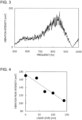
- Fig. 3 illustrates a waveform of a vibration intensity appearing in a frequency band of 600 Hz to 1000 Hz.
- the horizontal axis represents a frequency (Hz)
- the vertical axis represents a vibration intensity (m/s 2 ).
- this waveform has a broad peak in a frequency band of 800 Hz to 900 Hz, and therefore a relationship between a peak intensity of the peak and a liquid level was examined.
- Fig. 4 is a graph illustrating a relationship between a vibration peak intensity and a liquid level.
- the horizontal axis represents a liquid level (mm)
- the vertical axis represents an intensity (m/s 2 ) of a vibration peak appearing in a frequency band of 800 Hz to 900 Hz.
- the intensity of the vibration peak decreased as the liquid level increased, and a linear negative correlation was confirmed between the liquid level and the vibration peak intensity.
- a raceway formed in the container 32 during the experiments was observed. As a result, it was found that circling behavior of the filling particles 34 in the raceway changed depending on a change in liquid level, and it was estimated that vibration at 900 Hz is vibration resulting from circling of the filling particles 34 in the raceway. It can be hypothesized that a raceway shape also changed due to the change in liquid level and the circling behavior of the filling particles 34 also changed due to the change in raceway shape accordingly, and as a result the influence of the liquid level appeared in the vibration peak intensity at 900 Hz.
- the molten iron slag balance means a value obtained by subtracting an amount of tapped molten iron slag in terms of volume from an amount of generated molten iron slag in terms of volume.
- Molten iron slag balance "0" means that the amount of generated molten iron slag and the amount of tapped molten iron slag are equal.
- Positive molten iron slag balance means that the amount of tapped molten iron slag is smaller than the amount of generated molten iron slag, and therefore a molten iron slag height increases.
- negative molten iron slag balance means that the amount of tapped molten iron slag is larger than the amount of generated molten iron slag, and therefore the molten iron slag height decreases.
- W p is the amount of generated molten iron (t/time)
- W s is the amount of generated molten slag (t/time).
- N top is an amount of substance (mol/time) of oxygen atoms in furnace top gas per unit time
- N tuy is an amount of substance (mol/time) of oxygen atoms blown through a tuyere per unit time
- R Fe/O is an average number (-) of iron atoms per oxygen atom in iron oxide in the raw materials charged through the furnace top
- M Fe is a molar mass (t/mol) of iron
- R FeHM is a mass fraction (-) of iron in molten iron
- R G/Fe is a mass (t/ molten iron) of charged gangue per 1 t of molten iron. Note that (-) indicates being dimensionless.
- N top is found by component analysis of furnace top gas.
- N tuy is found by component analysis of gas blown through the tuyere.
- R Fe/O and R G/Fe are found by component analysis of the raw materials charged through the furnace top.
- R FeHM is found by component analysis of molten iron tapped through a taphole.
- Fig. 5 is a graph illustrating transition of the vibration peak intensity and the molten iron slag balance as the number of times of tapping increases.
- the horizontal axis represents the number of times of tapping (times)
- the left vertical axis represents a normalized vibration peak intensity (-)
- the right vertical axis represents normalized molten iron slag balance (-).
- the normalized vibration peak intensity and the normalized molten iron slag balance are values normalized by dividing the vibration peak intensity and the molten iron slag balance by maximum absolute values of the vibration peak intensity and the molten iron slag balance in a target period, respectively. As illustrated in Fig. 5 , such a negative correlation that the molten iron slag balance becomes negative as the vibration peak intensity increases was confirmed.
- Fig. 6 is a graph illustrating a relationship between the normalized vibration peak intensity and the normalized molten iron slag balance.
- the horizontal axis represents the normalized vibration peak intensity (-)
- the vertical axis represents the normalized molten iron slag balance (-).
- a linear negative correlation similar to that illustrated in Fig. 4 was confirmed between the normalized vibration peak intensity and the normalized molten iron slag balance. That is, it was confirmed that a vibration intensity in a specific frequency band of vibration emitted from a body of a lower portion of the blast furnace had a linear negative correlation with a molten iron slag height.
- a vibration intensity of a furnace wall of a lower portion of a blast furnace is measured while changing a molten iron slag height of the blast furnace, a frequency band that is correlated with the change in molten iron slag height is specified by frequency analysis of the vibration intensity, and a regression formula representing a correspondence between a vibration intensity in the frequency band and a molten iron slag height is found in advance.
- a raceway shape is influenced by a Bosch gas flow rate and a harmonic average grain size and an apparent density of coke, it is preferable to find the regression formula for each of these conditions.
- a vibration intensity in the specified frequency band is measured during operation of a blast furnace, and the molten iron slag height of the blast furnace is found by using the measured vibration intensity and the regression formula found in advance.
- the molten iron slag height of the blast furnace can be found without using a device for transmitting a signal to the blast furnace. This prevents device arrangement in a lower portion of the blast furnace and device maintenance from becoming difficult.
- the regression formula representing a correspondence between a vibration intensity in the frequency band and a molten iron slag height is preferably found every time of blowing down of the blast furnace. In a case where the molten iron slag balance is used, a change in liquid level of molten iron slag can be grasped, but a molten iron slag height in the blast furnace cannot be grasped.
- molten iron slag is discharged until a predetermined molten iron slag height is reached, and therefore a molten iron slag height can be calculated by calculating molten iron slag balance while using the predetermined molten iron slag height as a reference in operation of the blast furnace after blowing down.
- a molten iron slag height is calculated as described above, and therefore a regression formula representing a correspondence between a vibration intensity in the frequency band and a molten iron slag height can be found at any time.
- calculation accuracy of a molten iron height calculated from a reference molten iron slag height and molten iron slag balance decreases as blast furnace operation continues from a time when the reference molten iron slag height is found. It is therefore preferable to find a regression formula representing a correspondence between a vibration intensity in the frequency band and a molten iron slag height every time blowing down of a blast furnace is conducted. In this way, high detection accuracy of a molten iron slag height can be maintained.
Landscapes
- Engineering & Computer Science (AREA)
- Physics & Mathematics (AREA)
- Mechanical Engineering (AREA)
- General Engineering & Computer Science (AREA)
- Chemical & Material Sciences (AREA)
- Fluid Mechanics (AREA)
- General Physics & Mathematics (AREA)
- Materials Engineering (AREA)
- Metallurgy (AREA)
- Organic Chemistry (AREA)
- Manufacturing & Machinery (AREA)
- Thermal Sciences (AREA)
- Acoustics & Sound (AREA)
- Electromagnetism (AREA)
- Blast Furnaces (AREA)
- Manufacture Of Iron (AREA)
- Measurement Of Mechanical Vibrations Or Ultrasonic Waves (AREA)
Abstract
Description
- The present invention relates to a blast furnace molten iron slag height detection method and molten iron slag height detection apparatus.
- In operation of a blast furnace, main raw materials including iron ore and coke serving as a reductant are alternately charged through a furnace top, and heated air is blown through an air blowing opening called a tuyere located at a lower portion of the furnace. The charged iron ore is melted in the furnace and is reduced to become molten iron, and the molten iron is discharged through a taphole provided at a lower portion of the furnace together with molten slag, which is formed from gangue in the iron ore.
- Molten iron and molten slag (hereinafter collectively referred to as "molten iron slag") are always discharged through any of plural tapholes of the blast furnace, which are alternately used. This is because if an amount of molten iron slag accumulated in the blast furnace increases, operation of the blast furnace is negatively influenced. Specific examples of the negative influence include an increase in pressure loss in the furnace, breakage of the tuyere caused by the molten iron slag reaching the height of the tuyere, and failure to blow air caused by reverse flow of the molten iron slag from the tuyere toward a blow pipe. In particular, if a trouble occurs around the tuyere, there is no choice but to sustain blowing down for a long term. This may sometimes lead to a blast furnace hearth chill. Therefore, properly managing a molten iron slag height, which is a molten iron slag liquid level, is very important for stable operation of a blast furnace.
- In operation of a blast furnace, a molten iron slag height is managed by calculation of balance between a result of measurement of a weight of molten iron slag (hereinafter referred to as tapped molten iron slag") tapped through a taphole and an amount of generated molten iron slag calculated from an amount of charged raw materials. However, the result of measurement of a weight of tapped molten iron slag can be obtained only in a tapping cycle, specifically, every two to three hours, and therefore information on the molten iron slag height can be obtained only at this time interval. Therefore, obtaining more instantaneous information concerning a molten iron slag height is very important for stable operation of a blast furnace.
- As a technique for measuring a molten iron slag height, for example, Patent Literature 1 discloses a technique for detecting a molten iron slag height in a blast furnace on the basis of a reflection echo of an elastic wave emitted from a transmitter provided on a wall of a blast furnace. Furthermore, Patent Literature 2 discloses a technique for measuring a molten iron slag height by applying a signal current from four electrodes provided on a wall of a blast furnace and detecting a response of a voltage to the signal current.
-
- PTL 1:
Japanese Unexamined Patent Application Publication No. 10-185654 - PTL 2:
Japanese Unexamined Patent Application Publication No. 2010-138437 - However, according to the techniques disclosed in Patent Literatures 1 and 2, a transmitter that emits an elastic wave or electrodes for applying a signal current are needed in addition to a measurement device that receives a signal from an inside of a furnace. In a lower portion of the blast furnace where molten iron slag is stored, pieces of equipment such as a blow pipe for blowing air, a taphole opener, and a molten iron runner cover manipulator are closely arranged. Furthermore, a body of the lower portion of the blast furnace generates enormous dust and radiation heat during tapping work. Therefore, if an extra device for transmitting a signal is needed in addition to a measurement device, it is difficult to arrange these devices in the lower portion of the blast furnace and do maintenance of the devices. The present invention was accomplished in view of such problems of the conventional arts, and an object of the present invention is to provide a molten iron slag height detection method and a molten iron slag height detection apparatus that can find a molten iron slag height without using a device for transmitting a signal to a blast furnace. Solution to Problem
- Means for solving the above problems is as follows.
- (1) A molten iron slag height detection method for detecting a molten iron slag height of a blast furnace, the molten iron slag height detection method including: measuring a vibration intensity of a furnace wall of a lower portion of the blast furnace; calculating a vibration intensity in a frequency band correlated with a change in molten iron slag height by frequency analysis of the measured vibration intensity; and finding the molten iron slag height of the blast furnace by using the calculated intensity in the frequency band.
- (2) The molten iron slag height detection method according to (1), further including finding a correspondence relationship between the vibration intensity in the frequency band and the molten iron slag height in advance, in which the molten iron slag height of the blast furnace is found by using the calculated vibration intensity in the frequency band and the correspondence relationship.
- (3) The molten iron slag height detection method according to (2), in which the correspondence relationship is found every time of blowing down of the blast furnace.
- (4) A molten iron slag height detection apparatus for detecting a molten iron slag height of a blast furnace, the molten iron slag height detection apparatus including: a vibration meter that is provided on a furnace wall of a lower portion of the blast furnace and measures a vibration intensity of the furnace wall; and an arithmetic device that calculates a vibration intensity in a predetermined frequency band by frequency analysis of the vibration intensity measured by the vibration meter and calculates the molten iron slag height of the blast furnace by using a correspondence relationship between the vibration intensity in the predetermined frequency band and the molten iron slag height.
- According to the molten iron slag height detection method and the molten iron slag height detection apparatus according to the present invention, a molten iron slag height of a blast furnace is detected by measuring a vibration intensity of vibration emitted by the blast furnace itself during operation. Since the molten iron slag height detection method according to the present invention can thus detect a molten iron slag height of a blast furnace without using a device for transmitting a signal to the blast furnace, it is possible to prevent device arrangement and device maintenance from becoming difficult.
-
- [
Fig. 1] Fig. 1 is a cross-sectional schematic view of a lower portion of a blast furnace. - [
Fig. 2] Fig. 2 is a schematic view illustrating an experimental model used to confirm a relationship between vibration of a furnace wall in the lower portion of the blast furnace and a molten iron slag height. - [
Fig. 3] Fig. 3 illustrates a waveform of a vibration intensity appearing in a frequency band of 600 Hz to 1000 Hz. - [
Fig. 4] Fig. 4 is a graph illustrating a relationship between a vibration peak intensity and a liquid level. - [
Fig. 5] Fig. 5 is a graph illustrating transition of a vibration peak intensity and molten iron slag balance as the number of times of tapping increases. - [
Fig. 6] Fig. 6 is a graph illustrating a relationship between a normalized vibration peak intensity and normalized molten iron slag balance. - The present invention is described below on the basis of an embodiment of the invention.
Fig. 1 is a cross-sectional schematic view of a lower portion of ablast furnace 10. Iron ore and coke, which are raw materials, are alternately charged into a space inside afurnace wall 12 through a furnace top of theblast furnace 10 so as to form layers, and a hot blast, which is oxygen-containing gas, and a reductant such as pulverized coal are blown into the space inside thefurnace wall 12 through atuyere 14 provided in the lower portion of thefurnace wall 12. Carbon contained in the coke and the pulverized coal is burned by the oxygen-containing gas blown through thetuyere 14. This generates high-temperature reducing gas. The high-temperature reducing gas melts and reduces the iron ore, and thereby molten iron is produced. The high-temperature reducing gas used to melt and reduce the iron ore is then discharged as furnace top gas through the furnace top. The produced molten iron and molten slag produced as a by-product when the molten iron is produced, which aremolten iron slag 18, are accumulated in a furnace bottom portion and is discharged throughtapholes 16 provided in the lower portion of theblast furnace 10. - In the lower portion of the
blast furnace 10 where themolten iron slag 18 is accumulated, thefurnace wall 12 is faintly vibrating due to causes such as a pressure variation of blown air and cooling water, falling of raw materials in the furnace, and collision of coke circling in a raceway at a tip of the tuyere with an inner wall of thefurnace wall 12. Among these causes of the vibration, the pressure of blown air and the raceway shape change depending on a fluctuation in height of themolten iron slag 18. The inventors of the present invention focused on vibration in a specific frequency band resulting from a pressure variation of blown air and collision of coke in the raceway with thefurnace wall 12, which are influenced by the height of themolten iron slag 18, and found that a change in height of themolten iron slag 18 can be detected by detecting an intensity of the vibration and thus completed the present invention. - According to a molten iron slag height detection method according to the present embodiment, a height of the
molten iron slag 18 accumulated in the bottom portion is detected by using a molten iron slagheight detection apparatus 20. The molten iron slagheight detection apparatus 20 has avibration meter 22 and anarithmetic device 24. Thevibration meter 22 is provided in a hearth portion of thefurnace wall 12 in the lower portion, and measures a vibration intensity of thefurnace wall 12 and outputs the measured vibration intensity to thearithmetic device 24. Thevibration meter 22 is, for example, a piezoelectric element. Note that thevibration meter 22 is not limited to a piezoelectric element, and may measure displacement of thefurnace wall 12 by using a laser rangefinder, may electromagnetically measure vibration by using a coil or the like, or may mechanically measure vibration by using a spring or the like. It is however preferable to use a piezoelectric element that can be directly provided on thefurnace wall 12 and has a small number of movable parts since the hearth portion of theblast furnace 10 is in a harsh dust environment. - The
arithmetic device 24 is a general-purpose computer such as a personal computer that has an arithmetic unit such as a CPU and a storage unit such as a memory. Thearithmetic device 24 performs frequency analysis of the vibration intensity acquired from thevibration meter 22 and calculates a vibration intensity in a predetermined frequency band. Furthermore, thearithmetic device 24 stores therein in advance a regression formula representing a correspondence relationship between a vibration intensity in the frequency band and a molten iron slag height, and thearithmetic device 24 finds a molten iron slag height by using the calculated vibration intensity and the regression formula representing the correspondence relationship. In this way, according to the molten iron slag height detection method according to the present embodiment, a molten iron slag height of the blast furnace is detected without using a device for transmitting a signal to theblast furnace 10. - Next, an experiment that confirmed that a molten iron slag height of the
blast furnace 10 can be detected by using vibration of theblast furnace 10 is described.Fig. 2 is a schematic view illustrating anexperimental model 30 used to confirm a relationship between vibration of thefurnace wall 12 in the lower portion of the blast furnace and a molten iron slag height. Theexperimental model 30 has acontainer 32, twoair blowing tuyeres 36, a liquid inflow hole 44, apiezoelectric element 40, and adata logger 42. - The
container 32 is modeled after a part of the lower portion of theblast furnace 10 and is an acrylic container having a height of 950 mm, a depth of 120 mm, an upper end width of 460 mm, and a bottom width of 380 mm. Thecontainer 32 is opened on an upper side so that thecontainer 32 can be filled with fillingparticles 34. The twoair blowing tuyeres 36 are provided on a side surface of thecontainer 32 at a height of 185 mm from a bottom surface. The single liquid inflow hole 44 is provided at a center of gravity of the bottom surface of thecontainer 32. Aflow regulating valve 38 is provided on an upstream side of each of theair blowing tuyeres 36 so that an amount of air blown through theair blowing tuyeres 36 can be adjusted. Thepiezoelectric element 40 is disposed between the twoair blowing tuyeres 36. A temporal change of a vibration intensity was measured by converting vibration into an electric signal by thepiezoelectric element 40 and collecting and recording the electric signal by thedata logger 42. - In the experiment, the
container 32 was filled with a high-density polyethylene pellet (specific gravity: 0.922) having a diameter of 3.4 mm as the fillingparticles 34, and thecontainer 32 was filled with water to a predetermined height through the liquid inflow hole 44. In this state, the experiment was conducted by blowing a predetermined amount of air through theair blowing tuyeres 36. Experimental conditions are illustrated in Table 1 below.[Table 1] Experiment No Presence of filling particles Total amount of blown air (L/min) Liquid level (mm) 1 Not present 1442 0 2 present 1442 0 3 present 1442 40 4 present 1442 70 5 present 1442 100 6 present 1442 140 - An experiment No. 1 in which the
container 32 was not filled with the fillingparticles 34 nor water and experiments No. 2 to No. 6 in which thecontainer 32 was filled with the fillingparticles 34 and a liquid level was set to five different levels were conducted. As a result of frequency analysis of vibration measured in the experiments, a correlation was observed between a broad peak appearing in a frequency band of 800 Hz to 900 Hz and the presence or absence of the fillingparticles 34. -
Fig. 3 illustrates a waveform of a vibration intensity appearing in a frequency band of 600 Hz to 1000 Hz. InFig. 3 , the horizontal axis represents a frequency (Hz), and the vertical axis represents a vibration intensity (m/s2). As illustrated inFig. 3 , this waveform has a broad peak in a frequency band of 800 Hz to 900 Hz, and therefore a relationship between a peak intensity of the peak and a liquid level was examined. -
Fig. 4 is a graph illustrating a relationship between a vibration peak intensity and a liquid level. InFig. 4 , the horizontal axis represents a liquid level (mm), and the vertical axis represents an intensity (m/s2) of a vibration peak appearing in a frequency band of 800 Hz to 900 Hz. As illustrated inFig. 4 , the intensity of the vibration peak decreased as the liquid level increased, and a linear negative correlation was confirmed between the liquid level and the vibration peak intensity. - A raceway formed in the
container 32 during the experiments was observed. As a result, it was found that circling behavior of the fillingparticles 34 in the raceway changed depending on a change in liquid level, and it was estimated that vibration at 900 Hz is vibration resulting from circling of the fillingparticles 34 in the raceway. It can be hypothesized that a raceway shape also changed due to the change in liquid level and the circling behavior of the fillingparticles 34 also changed due to the change in raceway shape accordingly, and as a result the influence of the liquid level appeared in the vibration peak intensity at 900 Hz. - Since the above experiment result was obtained, it was examined whether a molten iron slag height of an actual blast furnace can be detected by using vibration emitted by the blast furnace. A piezoelectric vibration meter was mounted between tuyeres on an outer steel shell of a blast furnace having a 5000 m3 class capacity, and frequency characteristics were analyzed from a measurement result. As a result, a vibration peak having a vertex at a position of a frequency of approximately 900 Hz appeared, and an intensity of the vibration peak and molten iron slag balance were compared. The molten iron slag balance means a value obtained by subtracting an amount of tapped molten iron slag in terms of volume from an amount of generated molten iron slag in terms of volume. Molten iron slag balance "0" means that the amount of generated molten iron slag and the amount of tapped molten iron slag are equal. Positive molten iron slag balance means that the amount of tapped molten iron slag is smaller than the amount of generated molten iron slag, and therefore a molten iron slag height increases. On the other hand, negative molten iron slag balance means that the amount of tapped molten iron slag is larger than the amount of generated molten iron slag, and therefore the molten iron slag height decreases.
- The amount of generated molten iron slag was calculated from an oxygen balance of the blast furnace per unit time, a proportion of oxygen contained in iron oxide in raw materials charged through a furnace top, and a proportion of gangue in the charged raw materials. Specifically, an amount of generated molten iron was calculated by using the following formula (1), and an amount of generated molten slag was calculated by using the following formula (2), and an amount of generated molten iron slag was calculated by summing up these amounts.
[Math. 1]
[Math. 2]
- In the above formulas (1) and (2), Wp is the amount of generated molten iron (t/time), and Ws is the amount of generated molten slag (t/time). Ntop is an amount of substance (mol/time) of oxygen atoms in furnace top gas per unit time, Ntuy is an amount of substance (mol/time) of oxygen atoms blown through a tuyere per unit time, RFe/O is an average number (-) of iron atoms per oxygen atom in iron oxide in the raw materials charged through the furnace top, MFe is a molar mass (t/mol) of iron, RFeHM is a mass fraction (-) of iron in molten iron, and RG/Fe is a mass (t/ molten iron) of charged gangue per 1 t of molten iron. Note that (-) indicates being dimensionless.
- Ntop is found by component analysis of furnace top gas. Ntuy is found by component analysis of gas blown through the tuyere. RFe/O and RG/Fe are found by component analysis of the raw materials charged through the furnace top. RFeHM is found by component analysis of molten iron tapped through a taphole.
-
Fig. 5 is a graph illustrating transition of the vibration peak intensity and the molten iron slag balance as the number of times of tapping increases. InFig. 5 , the horizontal axis represents the number of times of tapping (times), the left vertical axis represents a normalized vibration peak intensity (-), and the right vertical axis represents normalized molten iron slag balance (-). The normalized vibration peak intensity and the normalized molten iron slag balance are values normalized by dividing the vibration peak intensity and the molten iron slag balance by maximum absolute values of the vibration peak intensity and the molten iron slag balance in a target period, respectively. As illustrated inFig. 5 , such a negative correlation that the molten iron slag balance becomes negative as the vibration peak intensity increases was confirmed. -
Fig. 6 is a graph illustrating a relationship between the normalized vibration peak intensity and the normalized molten iron slag balance. InFig. 6 , the horizontal axis represents the normalized vibration peak intensity (-), and the vertical axis represents the normalized molten iron slag balance (-). As illustrated inFig. 6 , a linear negative correlation similar to that illustrated inFig. 4 was confirmed between the normalized vibration peak intensity and the normalized molten iron slag balance. That is, it was confirmed that a vibration intensity in a specific frequency band of vibration emitted from a body of a lower portion of the blast furnace had a linear negative correlation with a molten iron slag height. - In view of these results, first, a vibration intensity of a furnace wall of a lower portion of a blast furnace is measured while changing a molten iron slag height of the blast furnace, a frequency band that is correlated with the change in molten iron slag height is specified by frequency analysis of the vibration intensity, and a regression formula representing a correspondence between a vibration intensity in the frequency band and a molten iron slag height is found in advance. Note that since a raceway shape is influenced by a Bosch gas flow rate and a harmonic average grain size and an apparent density of coke, it is preferable to find the regression formula for each of these conditions.
- When a molten iron slag height is measured, a vibration intensity in the specified frequency band is measured during operation of a blast furnace, and the molten iron slag height of the blast furnace is found by using the measured vibration intensity and the regression formula found in advance. In this way, the molten iron slag height of the blast furnace can be found without using a device for transmitting a signal to the blast furnace. This prevents device arrangement in a lower portion of the blast furnace and device maintenance from becoming difficult.
- The regression formula representing a correspondence between a vibration intensity in the frequency band and a molten iron slag height is preferably found every time of blowing down of the blast furnace. In a case where the molten iron slag balance is used, a change in liquid level of molten iron slag can be grasped, but a molten iron slag height in the blast furnace cannot be grasped. On the other hand, in a case where blowing down of the blast furnace is conducted, molten iron slag is discharged until a predetermined molten iron slag height is reached, and therefore a molten iron slag height can be calculated by calculating molten iron slag balance while using the predetermined molten iron slag height as a reference in operation of the blast furnace after blowing down.
- In operation of a blast furnace, a molten iron slag height is calculated as described above, and therefore a regression formula representing a correspondence between a vibration intensity in the frequency band and a molten iron slag height can be found at any time. However, calculation accuracy of a molten iron height calculated from a reference molten iron slag height and molten iron slag balance decreases as blast furnace operation continues from a time when the reference molten iron slag height is found. It is therefore preferable to find a regression formula representing a correspondence between a vibration intensity in the frequency band and a molten iron slag height every time blowing down of a blast furnace is conducted. In this way, high detection accuracy of a molten iron slag height can be maintained.
-
- 10
- blast furnace
- 12
- furnace wall
- 14
- tuyere
- 16
- taphole
- 18
- molten iron slag
- 20
- molten iron slag height detection apparatus
- 22
- vibration meter
- 24
- arithmetic device
- 30
- experimental model
- 32
- container
- 34
- filling particles
- 36
- air blowing tuyere
- 38
- flow regulating valve
- 40
- piezoelectric element
- 42
- data logger
- 44
- liquid inflow hole
Claims (4)
- A molten iron slag height detection method for detecting a molten iron slag height of a blast furnace, the molten iron slag height detection method comprising:measuring a vibration intensity of a furnace wall of a lower portion of the blast furnace;calculating a vibration intensity in a frequency band correlated with a change in molten iron slag height by frequency analysis of the measured vibration intensity; andfinding the molten iron slag height of the blast furnace by using the calculated intensity in the frequency band.
- The molten iron slag height detection method according to claim 1, further comprising finding a correspondence relationship between the vibration intensity in the frequency band and the molten iron slag height in advance,
wherein the molten iron slag height of the blast furnace is found by using the calculated vibration intensity in the frequency band and the correspondence relationship. - The molten iron slag height detection method according to claim 2, wherein
the correspondence relationship is found every time of blowing down of the blast furnace. - A molten iron slag height detection apparatus for detecting a molten iron slag height of a blast furnace, the molten iron slag height detection apparatus comprising:a vibration meter that is provided on a furnace wall of a lower portion of the blast furnace and measures a vibration intensity of the furnace wall; andan arithmetic device that calculates a vibration intensity in a predetermined frequency band by frequency analysis of the vibration intensity measured by the vibration meter and calculates the molten iron slag height of the blast furnace by using a correspondence relationship between the vibration intensity in the predetermined frequency band and the molten iron slag height.
Applications Claiming Priority (2)
| Application Number | Priority Date | Filing Date | Title |
|---|---|---|---|
| JP2021048716 | 2021-03-23 | ||
| PCT/JP2021/048557 WO2022201717A1 (en) | 2021-03-23 | 2021-12-27 | Molten iron slag height detection method and molten iron slag height detection device |
Publications (2)
| Publication Number | Publication Date |
|---|---|
| EP4286539A1 true EP4286539A1 (en) | 2023-12-06 |
| EP4286539A4 EP4286539A4 (en) | 2024-10-02 |
Family
ID=83396812
Family Applications (1)
| Application Number | Title | Priority Date | Filing Date |
|---|---|---|---|
| EP21933307.7A Pending EP4286539A4 (en) | 2021-03-23 | 2021-12-27 | METHOD FOR DETECTING THE HEIGHT OF MOLTEN IRON SLAG AND DEVICE FOR DETECTING THE HEIGHT OF MOLTEN IRON SLAG |
Country Status (5)
| Country | Link |
|---|---|
| EP (1) | EP4286539A4 (en) |
| JP (1) | JP7272509B2 (en) |
| KR (1) | KR20230145593A (en) |
| BR (1) | BR112023018627A2 (en) |
| WO (1) | WO2022201717A1 (en) |
Families Citing this family (11)
| Publication number | Priority date | Publication date | Assignee | Title |
|---|---|---|---|---|
| WO2024150464A1 (en) * | 2023-01-12 | 2024-07-18 | Jfeスチール株式会社 | Molten material height detection method, molten material height detection device, and molten material producing method |
| JP7485247B1 (en) * | 2023-01-12 | 2024-05-16 | Jfeスチール株式会社 | METHOD FOR DETECTING MELT HEIGHT, DEVICE FOR DETECTING MELT HEIGHT, AND MELT PRODUCTION METHOD |
| CN120641577A (en) | 2023-01-30 | 2025-09-12 | 杰富意钢铁株式会社 | Method for measuring melt level in blast furnace, device for measuring melt level in blast furnace, and method for operating blast furnace |
| CN120569495A (en) * | 2023-01-30 | 2025-08-29 | 杰富意钢铁株式会社 | Method for measuring melt height in blast furnace, device for measuring melt height in blast furnace, and method for operating blast furnace |
| WO2024161701A1 (en) * | 2023-01-30 | 2024-08-08 | Jfeスチール株式会社 | Method for measuring melt level inside blast furnace, device for measuring melt level inside blast furnace, and blast furnace operation method |
| JP7694749B1 (en) | 2024-02-28 | 2025-06-18 | Jfeスチール株式会社 | METHOD FOR DETECTING MELT HEIGHT, DEVICE FOR DETECTING MELT HEIGHT, AND MELT PRODUCTION METHOD |
| JP7694748B1 (en) * | 2024-02-28 | 2025-06-18 | Jfeスチール株式会社 | METHOD FOR MEASURING MOLTEN MATERIAL LEVEL IN BLAST FURNACE, MEASURING DEVICE FOR MOLTEN MATERIAL LEVEL IN BLAST FURNACE, AND METHOD FOR OPERATING BLAST FURNACE |
| JP7694747B1 (en) * | 2024-02-28 | 2025-06-18 | Jfeスチール株式会社 | METHOD FOR MEASURING MOLTEN MATERIAL LEVEL IN BLAST FURNACE, MEASURING DEVICE FOR MOLTEN MATERIAL LEVEL IN BLAST FURNACE, AND METHOD FOR OPERATING BLAST FURNACE |
| WO2026014015A1 (en) * | 2024-07-09 | 2026-01-15 | Jfeスチール株式会社 | Molten material height detection method, molten material height detection device, and molten material producing method |
| JP7740605B1 (en) * | 2024-07-09 | 2025-09-17 | Jfeスチール株式会社 | METHOD FOR DETECTING MELT HEIGHT, DEVICE FOR DETECTING MELT HEIGHT, AND MELT PRODUCTION METHOD |
| WO2026069955A1 (en) * | 2024-09-24 | 2026-04-02 | Jfeスチール株式会社 | Molten material height detection method, molten material height detection device, and molten material production method |
Family Cites Families (7)
| Publication number | Priority date | Publication date | Assignee | Title |
|---|---|---|---|---|
| JPH0466611A (en) * | 1990-07-03 | 1992-03-03 | Sumitomo Metal Ind Ltd | Method for detecting abnormality at front of blasting tuyere in blast furnace |
| JPH0625719A (en) * | 1992-07-08 | 1994-02-01 | Nkk Corp | Method for preventing blowoff in blast furnace |
| JP3596125B2 (en) * | 1995-11-22 | 2004-12-02 | Jfeスチール株式会社 | Method and apparatus for measuring liquid level of molten material in furnace |
| JPH10185654A (en) | 1996-12-20 | 1998-07-14 | Kawasaki Steel Corp | Method for detecting liquid level of furnace melt |
| JP5412819B2 (en) | 2008-12-10 | 2014-02-12 | Jfeスチール株式会社 | Method and apparatus for measuring melt level in vertical furnace |
| KR101043092B1 (en) * | 2009-08-17 | 2011-06-21 | 재단법인 포항산업과학연구원 | Molten steel inclusion furnace condition analysis device and method |
| DE102014204239A1 (en) * | 2014-03-07 | 2015-09-10 | Siemens Aktiengesellschaft | Method for determining the variation of a slag height |
-
2021
- 2021-12-27 JP JP2022521126A patent/JP7272509B2/en active Active
- 2021-12-27 KR KR1020237031763A patent/KR20230145593A/en active Pending
- 2021-12-27 WO PCT/JP2021/048557 patent/WO2022201717A1/en not_active Ceased
- 2021-12-27 EP EP21933307.7A patent/EP4286539A4/en active Pending
- 2021-12-27 BR BR112023018627A patent/BR112023018627A2/en unknown
Also Published As
| Publication number | Publication date |
|---|---|
| JPWO2022201717A1 (en) | 2022-09-29 |
| WO2022201717A1 (en) | 2022-09-29 |
| JP7272509B2 (en) | 2023-05-12 |
| EP4286539A4 (en) | 2024-10-02 |
| CN117043360A (en) | 2023-11-10 |
| KR20230145593A (en) | 2023-10-17 |
| BR112023018627A2 (en) | 2023-11-07 |
Similar Documents
| Publication | Publication Date | Title |
|---|---|---|
| JP7272509B2 (en) | Hot metal slag height detection method and hot metal slag height detection device | |
| EP3546600A1 (en) | Device and method for measuring surface level of molten metal | |
| CN102791399B (en) | Converter splash prediction and oxygen lance optimization system | |
| EP4282987A1 (en) | Method for detecting height of molten material | |
| US20080307926A1 (en) | Method for Determining the Properties of the Content of an Arc Furnace | |
| RU2825734C1 (en) | Method and device for determining residual amount of liquid, method and device for determining residual amount of liquid material and method of operating vertical furnace | |
| EP4269626A1 (en) | Detection method and detection device for liquid level height of liquid, detection method and detection device for liquid level height of molten material, and operation method for vertical furnace | |
| EP4269625A1 (en) | Method for detecting remaining amount of liquid and detection device for same, method for detecting remaining amount of molten substance and detection device for same, and vertical furnace operation method | |
| KR20110072934A (en) | Melt level measuring device using pressure sensor | |
| RU2815506C1 (en) | Method and device for determining liquid level, method and device for determining liquid level for liquid material and method of operating vertical furnace | |
| KR20250129752A (en) | Method for measuring the level of molten material in a blast furnace, device for measuring the level of molten material in a blast furnace, and method for operating a blast furnace | |
| KR101277237B1 (en) | Method for discriminating center gas flow in blast furnace and apparatus thereof | |
| JPH03134109A (en) | Method for measuring layer height of charged material in smelting furnace | |
| JP4181075B2 (en) | Early detection method for blast furnace hearth temperature level | |
| KR20230124064A (en) | Melt height detection method and blast furnace operation method | |
| KR101134620B1 (en) | Apparatus for inspecting molten iron in blast furnace | |
| JPH04285105A (en) | Method for grasping wall dropping condition in high temperature heating furnace | |
| JP2025175398A (en) | Molten metal and slag liquid level determination method, blast furnace operation method, and molten metal and slag liquid level determination device | |
| JP2025131312A (en) | METHOD FOR MEASURING MOLTEN MATERIAL LEVEL IN A BLAST FURNACE, MEASURING DEVICE FOR MOLTEN MATERIAL LEVEL IN A BLAST FURNACE, AND METHOD FOR OPERATING A BLAST FURNACE | |
| WO2022168556A1 (en) | Method for detecting remaining amount of liquid and detection device for same, method for detecting remaining amount of molten substance and detection device for same, and vertical furnace operation method | |
| JPH0625368B2 (en) | Blast furnace operation method | |
| WO2022168557A1 (en) | Detection method and detection device for liquid level height of liquid, detection method and detection device for liquid level height of molten material, and operation method for vertical furnace | |
| WO2022168503A1 (en) | Method for detecting height of molten material and method for operating blast furnace | |
| JPS60248805A (en) | Detection of condition of packing material in blast furnace | |
| JP2006249501A (en) | Gas sampling device, cohesive zone position determining method, and blast furnace operating method |
Legal Events
| Date | Code | Title | Description |
|---|---|---|---|
| STAA | Information on the status of an ep patent application or granted ep patent |
Free format text: STATUS: THE INTERNATIONAL PUBLICATION HAS BEEN MADE |
|
| PUAI | Public reference made under article 153(3) epc to a published international application that has entered the european phase |
Free format text: ORIGINAL CODE: 0009012 |
|
| STAA | Information on the status of an ep patent application or granted ep patent |
Free format text: STATUS: REQUEST FOR EXAMINATION WAS MADE |
|
| 17P | Request for examination filed |
Effective date: 20230829 |
|
| AK | Designated contracting states |
Kind code of ref document: A1 Designated state(s): AL AT BE BG CH CY CZ DE DK EE ES FI FR GB GR HR HU IE IS IT LI LT LU LV MC MK MT NL NO PL PT RO RS SE SI SK SM TR |
|
| DAV | Request for validation of the european patent (deleted) | ||
| DAX | Request for extension of the european patent (deleted) | ||
| A4 | Supplementary search report drawn up and despatched |
Effective date: 20240903 |
|
| RIC1 | Information provided on ipc code assigned before grant |
Ipc: G01F 23/00 20220101ALI20240828BHEP Ipc: F27B 1/28 20060101ALI20240828BHEP Ipc: F27D 21/00 20060101ALI20240828BHEP Ipc: C21B 7/24 20060101AFI20240828BHEP |