EP4286306A1 - Image forming apparatus - Google Patents
Image forming apparatus Download PDFInfo
- Publication number
- EP4286306A1 EP4286306A1 EP23169692.3A EP23169692A EP4286306A1 EP 4286306 A1 EP4286306 A1 EP 4286306A1 EP 23169692 A EP23169692 A EP 23169692A EP 4286306 A1 EP4286306 A1 EP 4286306A1
- Authority
- EP
- European Patent Office
- Prior art keywords
- sheet
- side end
- image forming
- blowing
- blowing fan
- Prior art date
- Legal status (The legal status is an assumption and is not a legal conclusion. Google has not performed a legal analysis and makes no representation as to the accuracy of the status listed.)
- Pending
Links
Images







Classifications
-
- B—PERFORMING OPERATIONS; TRANSPORTING
- B65—CONVEYING; PACKING; STORING; HANDLING THIN OR FILAMENTARY MATERIAL
- B65H—HANDLING THIN OR FILAMENTARY MATERIAL, e.g. SHEETS, WEBS, CABLES
- B65H1/00—Supports or magazines for piles from which articles are to be separated
- B65H1/04—Supports or magazines for piles from which articles are to be separated adapted to support articles substantially horizontally, e.g. for separation from top of pile
-
- B—PERFORMING OPERATIONS; TRANSPORTING
- B65—CONVEYING; PACKING; STORING; HANDLING THIN OR FILAMENTARY MATERIAL
- B65H—HANDLING THIN OR FILAMENTARY MATERIAL, e.g. SHEETS, WEBS, CABLES
- B65H3/00—Separating articles from piles
- B65H3/08—Separating articles from piles using pneumatic force
-
- B—PERFORMING OPERATIONS; TRANSPORTING
- B65—CONVEYING; PACKING; STORING; HANDLING THIN OR FILAMENTARY MATERIAL
- B65H—HANDLING THIN OR FILAMENTARY MATERIAL, e.g. SHEETS, WEBS, CABLES
- B65H3/00—Separating articles from piles
- B65H3/46—Supplementary devices or measures to assist separation or prevent double feed
- B65H3/48—Air blast acting on edges of, or under, articles
-
- G—PHYSICS
- G03—PHOTOGRAPHY; CINEMATOGRAPHY; ANALOGOUS TECHNIQUES USING WAVES OTHER THAN OPTICAL WAVES; ELECTROGRAPHY; HOLOGRAPHY
- G03G—ELECTROGRAPHY; ELECTROPHOTOGRAPHY; MAGNETOGRAPHY
- G03G15/00—Apparatus for electrographic processes using a charge pattern
- G03G15/65—Apparatus which relate to the handling of copy material
- G03G15/6502—Supplying of sheet copy material; Cassettes therefor
- G03G15/6511—Feeding devices for picking up or separation of copy sheets
-
- B—PERFORMING OPERATIONS; TRANSPORTING
- B65—CONVEYING; PACKING; STORING; HANDLING THIN OR FILAMENTARY MATERIAL
- B65H—HANDLING THIN OR FILAMENTARY MATERIAL, e.g. SHEETS, WEBS, CABLES
- B65H2403/00—Power transmission; Driving means
- B65H2403/40—Toothed gearings
- B65H2403/41—Rack-and-pinion, cogwheel in cog railway
- B65H2403/411—Double rack cooperating with one pinion, e.g. for performing symmetrical displacement relative to pinion
-
- B—PERFORMING OPERATIONS; TRANSPORTING
- B65—CONVEYING; PACKING; STORING; HANDLING THIN OR FILAMENTARY MATERIAL
- B65H—HANDLING THIN OR FILAMENTARY MATERIAL, e.g. SHEETS, WEBS, CABLES
- B65H2405/00—Parts for holding the handled material
- B65H2405/10—Cassettes, holders, bins, decks, trays, supports or magazines for sheets stacked substantially horizontally
- B65H2405/11—Parts and details thereof
- B65H2405/111—Bottom
- B65H2405/1115—Bottom with surface inclined, e.g. in width-wise direction
- B65H2405/11152—Bottom with surface inclined, e.g. in width-wise direction with surface inclined downwardly in transport direction
-
- B—PERFORMING OPERATIONS; TRANSPORTING
- B65—CONVEYING; PACKING; STORING; HANDLING THIN OR FILAMENTARY MATERIAL
- B65H—HANDLING THIN OR FILAMENTARY MATERIAL, e.g. SHEETS, WEBS, CABLES
- B65H2405/00—Parts for holding the handled material
- B65H2405/10—Cassettes, holders, bins, decks, trays, supports or magazines for sheets stacked substantially horizontally
- B65H2405/11—Parts and details thereof
- B65H2405/114—Side, i.e. portion parallel to the feeding / delivering direction
-
- B—PERFORMING OPERATIONS; TRANSPORTING
- B65—CONVEYING; PACKING; STORING; HANDLING THIN OR FILAMENTARY MATERIAL
- B65H—HANDLING THIN OR FILAMENTARY MATERIAL, e.g. SHEETS, WEBS, CABLES
- B65H2405/00—Parts for holding the handled material
- B65H2405/30—Other features of supports for sheets
- B65H2405/32—Supports for sheets partially insertable - extractable, e.g. upon sliding movement, drawer
- B65H2405/324—Supports for sheets partially insertable - extractable, e.g. upon sliding movement, drawer between operative position and non operative position
-
- B—PERFORMING OPERATIONS; TRANSPORTING
- B65—CONVEYING; PACKING; STORING; HANDLING THIN OR FILAMENTARY MATERIAL
- B65H—HANDLING THIN OR FILAMENTARY MATERIAL, e.g. SHEETS, WEBS, CABLES
- B65H2406/00—Means using fluid
- B65H2406/10—Means using fluid made only for exhausting gaseous medium
-
- B—PERFORMING OPERATIONS; TRANSPORTING
- B65—CONVEYING; PACKING; STORING; HANDLING THIN OR FILAMENTARY MATERIAL
- B65H—HANDLING THIN OR FILAMENTARY MATERIAL, e.g. SHEETS, WEBS, CABLES
- B65H2406/00—Means using fluid
- B65H2406/10—Means using fluid made only for exhausting gaseous medium
- B65H2406/12—Means using fluid made only for exhausting gaseous medium producing gas blast
- B65H2406/121—Fan
-
- B—PERFORMING OPERATIONS; TRANSPORTING
- B65—CONVEYING; PACKING; STORING; HANDLING THIN OR FILAMENTARY MATERIAL
- B65H—HANDLING THIN OR FILAMENTARY MATERIAL, e.g. SHEETS, WEBS, CABLES
- B65H2406/00—Means using fluid
- B65H2406/10—Means using fluid made only for exhausting gaseous medium
- B65H2406/12—Means using fluid made only for exhausting gaseous medium producing gas blast
- B65H2406/121—Fan
- B65H2406/1211—Axial
-
- B—PERFORMING OPERATIONS; TRANSPORTING
- B65—CONVEYING; PACKING; STORING; HANDLING THIN OR FILAMENTARY MATERIAL
- B65H—HANDLING THIN OR FILAMENTARY MATERIAL, e.g. SHEETS, WEBS, CABLES
- B65H2406/00—Means using fluid
- B65H2406/10—Means using fluid made only for exhausting gaseous medium
- B65H2406/12—Means using fluid made only for exhausting gaseous medium producing gas blast
- B65H2406/122—Nozzles
-
- B—PERFORMING OPERATIONS; TRANSPORTING
- B65—CONVEYING; PACKING; STORING; HANDLING THIN OR FILAMENTARY MATERIAL
- B65H—HANDLING THIN OR FILAMENTARY MATERIAL, e.g. SHEETS, WEBS, CABLES
- B65H2407/00—Means not provided for in groups B65H2220/00 – B65H2406/00 specially adapted for particular purposes
- B65H2407/20—Means not provided for in groups B65H2220/00 – B65H2406/00 specially adapted for particular purposes for manual intervention of operator
- B65H2407/21—Manual feeding
-
- B—PERFORMING OPERATIONS; TRANSPORTING
- B65—CONVEYING; PACKING; STORING; HANDLING THIN OR FILAMENTARY MATERIAL
- B65H—HANDLING THIN OR FILAMENTARY MATERIAL, e.g. SHEETS, WEBS, CABLES
- B65H2511/00—Dimensions; Position; Numbers; Identification; Occurrences
- B65H2511/10—Size; Dimensions
- B65H2511/12—Width
-
- B—PERFORMING OPERATIONS; TRANSPORTING
- B65—CONVEYING; PACKING; STORING; HANDLING THIN OR FILAMENTARY MATERIAL
- B65H—HANDLING THIN OR FILAMENTARY MATERIAL, e.g. SHEETS, WEBS, CABLES
- B65H2511/00—Dimensions; Position; Numbers; Identification; Occurrences
- B65H2511/20—Location in space
- B65H2511/22—Distance
-
- B—PERFORMING OPERATIONS; TRANSPORTING
- B65—CONVEYING; PACKING; STORING; HANDLING THIN OR FILAMENTARY MATERIAL
- B65H—HANDLING THIN OR FILAMENTARY MATERIAL, e.g. SHEETS, WEBS, CABLES
- B65H2551/00—Means for control to be used by operator; User interfaces
- B65H2551/20—Display means; Information output means
- B65H2551/29—Means displaying permanently a particular information, e.g. mark, ruler
-
- B—PERFORMING OPERATIONS; TRANSPORTING
- B65—CONVEYING; PACKING; STORING; HANDLING THIN OR FILAMENTARY MATERIAL
- B65H—HANDLING THIN OR FILAMENTARY MATERIAL, e.g. SHEETS, WEBS, CABLES
- B65H2601/00—Problem to be solved or advantage achieved
- B65H2601/20—Avoiding or preventing undesirable effects
- B65H2601/27—Other problems
- B65H2601/273—Adhering of handled material to another handled material or to part of the handling machine
-
- B—PERFORMING OPERATIONS; TRANSPORTING
- B65—CONVEYING; PACKING; STORING; HANDLING THIN OR FILAMENTARY MATERIAL
- B65H—HANDLING THIN OR FILAMENTARY MATERIAL, e.g. SHEETS, WEBS, CABLES
- B65H2801/00—Application field
- B65H2801/03—Image reproduction devices
-
- B—PERFORMING OPERATIONS; TRANSPORTING
- B65—CONVEYING; PACKING; STORING; HANDLING THIN OR FILAMENTARY MATERIAL
- B65H—HANDLING THIN OR FILAMENTARY MATERIAL, e.g. SHEETS, WEBS, CABLES
- B65H2801/00—Application field
- B65H2801/03—Image reproduction devices
- B65H2801/06—Office-type machines, e.g. photocopiers
Definitions
- the present invention relates to an image forming apparatus forming an image on a sheet.
- Japanese Patent Laid-open No. 2006-256819 discloses an art to help separate the sheets by blowing air on side ends of a sheet bundle set on a manual feed tray.
- a blower is protruded outside of a sheet stacking region on the manual feed tray, and thereby making a device larger for a space required to dispose the blower.
- the present invention makes possible to save space in a configuration that blows air to the sheet.
- One aspect of the present invention is an image forming apparatus comprising, an image forming portion configured to form an image on a sheet, a tray rotatably provided on a side surface of a main assembly accommodating the image forming portion and including a stacking surface on which the sheet is stacked, a feeding portion configured to feed the sheet stacked on the stacking surface toward the image forming portion, and a blowing fan mounted on the tray and configured to generate air blown to a side end of the sheet with respect to a sheet widthwise direction perpendicular to a feeding direction of the sheet by the feeding portion, wherein the blowing fan is disposed on an opposite side to a side where the sheet is stacked on the stacking surface so that a position of at least a part of the blowing fan with respect to the sheet widthwise direction is overlapped with a position of the stacking surface with respect to the sheet widthwise direction.
- an "image forming apparatus” refers to an apparatus forming an image on a sheet as a recording material.
- the image forming apparatus includes a printer, a copy machine, a multifunctional machine, a commercial printing machine, etc.
- FIG. 1 is a cross-sectional view illustrating a schematic configuration of an image forming apparatus 201 according to an embodiment (Embodiment 1).
- the image forming apparatus 201 is a laser beam printer of a tandem-type and of an intermediate transfer method using an electrophotographic image forming process.
- the image forming apparatus 201 can form and output a full-color or a single-color image on a sheet S based on image data.
- As the sheet S a variety of sheets of different sizes and materials may be used, including a plain paper and a thick paper, a plastic film, a cloth, a sheet material with a surface treatment such as a coated paper, a sheet material having a special shape such as an envelope and an index paper.
- the image forming apparatus 201 is provided with a main assembly 201A accommodating an image forming portion 201B, an image reading apparatus 202 disposed above the main assembly 201A reading image information from a document, and a control portion 100 controlling an entire apparatus operation ( Figure 2 ).
- the image forming portion 201B which is an example of an image forming portion, includes four process units PY, PM, PC, and PK, an exposure device 210, a transfer belt 216, and a fixing device 201E.
- a discharge space V for discharging the sheets is formed between the image reading apparatus 202 and the main assembly 201A.
- Each process unit PY, PM, PC and PK includes a photosensitive drum 212 as an image bearing member, a charging device 213 as a process portion acting on the photosensitive drum 212, a developing device 214, a cleaning device, etc.
- the photosensitive drum 212 is an electrophotographic photosensitive member formed in a drum shaped.
- the developing device 214 accommodates either of a yellow, a magenta, a cyan, or a black toner as a developer.
- the exposure device 210 as the process portion (exposure portion) is disposed below the process units PY, PM, PC, and PK.
- the transfer belt 216 is an example of an intermediary transfer member.
- the transfer belt 216 is wound around a drive roller 216a and a tension roller 216b.
- four primary transfer rollers 219 are disposed at a position opposite to the corresponding photosensitive drums 212 across the transfer belt 216, respectively.
- the transfer belt 216 is rotated in a counterclockwise direction as shown in an arrow in the figure by a drive roller 216a driven by a drive portion not shown.
- a secondary transfer roller 217 is disposed at a position, opposite to the drive roller 216a across the transfer belt 216.
- a transfer portion 201D (secondary transfer portion) is formed as a nip portion between the secondary transfer roller 217 and the transfer belt 216.
- a fixing device 201E is disposed above the transfer portion 201D.
- the fixing device 201E is a thermal fixing method provided with a heating roller 220b heated by a heating portion such as a halogen lamp, and a pressing roller 220a being pressurized against the heating roller 220b.
- a first discharge roller pair 225a, a second discharge roller pair 225b, and a double-sided reversing portion 201F are disposed.
- the double-sided reversing portion 201F includes a reversing roller pair 222 which can be rotated in a forward direction and a reverse direction and a reconveyance path R.
- an operating portion 730 receiving operations from a user is disposed.
- the operating portion 730 includes a display device such as a liquid crystal panel displaying images, and an input device such as a numeric keypad and a printing execution button.
- the user can input setting information (type, basis weight, size, brand name, etc.) of the sheet S set in a cassette feeding portion 230 and a manual feeding portion 235 via the operating portion 730.
- the cassette feeding portion 230 is disposed at a lower portion of the main assembly 201A.
- the manual feeding portion 235 is disposed at a side surface portion of the main assembly 201A.
- the cassette feeding portion 230 and the manual feeding portion 235 are an example of a sheet feeding device feeding the sheet.
- the cassette feeding portion 230 is provided with a cassette 1 as a sheet accommodating portion accommodating the sheet S and a pickup roller 2 as a feeding portion feeding the sheet S from the cassette 1.
- the cassette feeding portion 230 is provided with a separating roller pair constituted by a feed roller 3 and a retard roller 4 as a separation conveyance portion for separating the sheet S fed from the pickup roller 2.
- the retard roller 4 applies a frictional force to the sheet S in a nip portion between the retard roller 4 and the feed roller 3 in an opposite direction to a feeding direction, thereby permitting only a single sheet S in contact with the feed roller 3 to pass through the nip portion.
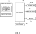
- FIG. 2 is a block diagram illustrating a system configuration of the image forming apparatus 201.
- a control portion 100 is a control portion controlling operations of the image forming apparatus 201 comprehensively and transfers information to and from a host device 900 and the operating portion 730.
- the control portion 100 controls operations of the image forming portion 201B, and of a feeding and a conveyance of the sheets, etc.
- the host device 900 is a personal computer, an image scanner, a facsimile, etc.
- a storage portion 101 stores programs executed by the control portion 100 and data necessary to execute the programs.
- the storage portion 101 provides a workspace when the control portion 100 executes the program.
- the control portion 100 controls operations of the image forming apparatus 201 based on the setting information entered by the user via the operating portion 730 and the image data received from the host device 900. For example, the control portion 100 controls a sheet feeding operation by driving an actuator (motor, etc.) of the manual feeding portion 235. In addition, the control portion 100 actuates blowing fans 15a and 15b described below when the control portion 100 determines that a separation by blowing air is necessary based on the setting information of the sheet (e.g., in cases of the coated paper).
- the control portion of the image forming apparatus 201 starts an image forming operation when the control portion receives the image data from the external device or receives the image data read from a document by the image reading apparatus 202 as an execution instruction of a copying operation is given.
- each of the process units PY, PM, PC, and PK forms a toner image on a surface of the photosensitive drum 212 by an electrophotographic process. That is, when a formation of the toner image is requested to the process units PY, PM, PC, and PK, the photosensitive drum 212 is driven and rotated, and the charging device 213 uniformly charges the surface of the photosensitive drum 212.
- the exposure device 210 irradiates a laser beam onto the photosensitive drum 212 based on the image data received from the outside by the control portion or the image data read from the document by the image reading apparatus 202. As a result, the surface of photosensitive drum 212 is exposed and an electrostatic latent image is formed.
- the developing device 214 supplies the developer containing the toner to the photosensitive drum 212 and develops the electrostatic latent image into the toner image.
- the toner images formed by the process units PY, PM, PC, and PK are primarily transferred to the transfer belt 216 by the primary transfer roller 219.
- the primary transfer is performed so that the toner images of each color overlap on the transfer belt 216, and thereby forming a color image on the transfer belt 216.
- Adhesive materials such as the toner remaining on the photosensitive drum 151 is removed by the cleaning device of each of the process units PY, PM, PC, and PK.
- the sheets S are fed one by one from the cassette feeding portion 230 or the manual feeding portion 235 and conveyed to a registration roller pair 240.
- the registration roller pair 240 conveys the sheet S to the transfer portion 201D at a timing synchronized with the operation of the image forming portion 201B.
- the toner image is secondarily transferred from the transfer belt 216 to the sheet S by the secondary transfer roller 217 to which transfer voltage is applied.
- the sheet S that has passed through the transfer portion 201D is conveyed to the fixing device 201E.
- the fixing device 201E heats and pressurizes the toner image on the sheet S while nipping and conveying the sheet S between the heating roller 220b and the pressing roller 220a. By this, a fixed image is produced on the sheet S. Incidentally, a sticking force to the heating roller 220b is generated on the sheet S due to an adhesive force of the melted toner. If a stiffness of the sheet S is low (weak), the sheet S may be wound around the rotating heating roller 220b, therefore a separating plate 221 is disposed at a downstream side of the heating roller 220b to separate the sheet.
- the sheet S that has passed through the fixing device 201E is discharged into the discharge space V by the first discharge roller pair 225a or the second discharge roller pair 225b, and is stacked on a discharge tray 223.
- the sheet S of which the image is formed on a first side by passing through the transfer portion 201D and the fixing device 201E is reversed by the reversing roller pair 222 and conveyed again to the image forming portion 201B via the reconveyance path R.
- the sheet S on which an image is formed on a second side by passing through the transfer portion 201D and the fixing device 201E again is discharged into the discharge space V by the first discharge roller pair 225a or the second discharge roller pair 225b, and is stacked on the discharge tray 223.
- the image forming portion 201B is an example of an image forming portion and instead of the image forming portion 201B, an electrophotographic unit of a direct transfer method or an image forming unit of an inkjet method or of an offset printing method may be used.
- FIG. 3 is a schematic view of the manual feeding portion 235 as viewed from above.
- the manual feeding portion 235 is configured so that the user sets a necessary amount of the sheets when using the image forming apparatus 201. Therefore, the cassette feeding cassette 230 is suitable for using sheets of a plain paper with a standard size which are frequently used, while the manual feeding portion 235 is suitable for using sheets such as the coated paper and a long sheet which are less frequently used.
- a “feeding direction Y” represents a direction in which sheets are fed from a feed tray 5 by a pickup roller 502.
- a “sheet widthwise direction X” represents a direction which is along the sheet stacked on the feed tray 5 and is perpendicular to the feeding direction Y
- the manual feeding portion 235 is provided with the feed tray 5, the pickup roller 502, a feed roller 503, a retard roller 504, a side end guide 14a and a side end guide 14b, and a blowing fan 15a and a blowing fan 15b.
- the feed tray 5 is a tray (stacking member) on which sheets are stacked.
- the feed tray 5 includes a stacking surface 5a (a support surface supporting a lower surface of a sheet, a mounting surface) on which a sheet is stacked.
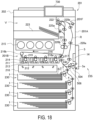
- the feed tray 5 can be rotated (openable and closable), with a support portion 5e (hinge portion) as a rotational center, between an accommodated position (see Figure 18 ) in which the feed tray 5 is accommodated in the side surface portion of the main assembly 201A of the image forming apparatus 201 and a feeding position in which the feed tray 5 is protruding outside the main assembly 201A and capable of feeding the sheets.
- the feed tray 5 is also called as a manual feed tray or a multi-purpose tray.
- the pickup roller 502 is an example of a feeding portion feeding the sheets.
- the pickup roller 502 is disposed above the stacking surface 5a of the feed tray 5.
- the pickup roller 502 is rotatably supported by a roller holder as a holding member.
- the roller holder is swingable about a rotation axis of the feed roller 503.
- the pickup roller 502 moves between a feeding position (contact position, lower position) where the pickup roller 502 contacts an upper surface of the sheet stacked on the feed tray 5, and a standby position (separation position, upper position) where the pickup roller 502 is separated above from the sheet.
- the sheet is fed from the feed tray 5 in the feeding direction Y as the pickup roller 502 rotates in the feeding position.
- a mechanism conveying the sheet for example, by adsorbing the sheet to a belt by a negative pressure generated by a fan and rotating the belt may be used.
- the feed roller 503 further conveys the sheet received from the pickup roller 502 in the feeding direction Y
- a conveyance roller pair 506 is disposed downstream of the feed roller 503 that conveys the sheet received from the feed roller 503 toward the registration roller pair 240 ( Figure 1 ).
- the retard roller 504 is pressurized against the feed roller 503 and forms a separation nip between the feed roller 503 and the retard roller 504.
- a driving force in a direction that goes against a rotation of the feed roller 503 is inputted to the retard roller 504 via a torque limiter.
- the retard roller 504 is an example of a separating member separating the sheet with a frictional force and instead of the retard roller 504, for example, a roller member connected to a fixed shaft via the torque limiter or a pad-shaped elastic member abutting the feed roller 503 may be used.
- the side end guides 14a and 14b are regulating members (regulating plates) regulating a position of the sheet with respect to the sheet widthwise direction X.
- a pair of the side end guides 14a and 14b facing each other with respect to the sheet widthwise direction X is used.
- the side end guide 14b of a rear side is a second side end guide disposed opposite to the side end guide 14a as a first side end guide with respect to the sheet widthwise direction X.
- the side end guides 14a and14b are provided with regulating surfaces 14a1 and 14b 1 as inside surfaces with respect to the sheet widthwise direction X, respectively.
- the regulating surfaces 14a1 and 14b 1 are surfaces extending in the feeding direction Y and rising substantially perpendicular to the feed tray 5 as viewed in the feeding direction Y
- the regulating surfaces 14a1 and 14b 1 regulate the position of the sheet with respect to the sheet widthwise direction X by abutting end portions in the sheet widthwise direction X of the sheet (side ends of the sheet) stacked on the feed tray 5.
- the side end guides 14a and 14b are movable in the sheet widthwise direction X relative to the feed tray 5.
- the side end guides 14a and 14b are connected by an interrelating mechanism such as a rack and pinion mechanism and move in interrelation with each other so that a distance from a center position X0 to each of the side end guides in the sheet widthwise direction X is the same.
- the center position X0 is a reference position in the sheet widthwise direction X of the sheets that the manual feeding portion 235 feeds.
- One of the side end guides 14a and 14b (the side end guide 14a on a front side of the image forming apparatus 201) is provided with an operating knob 18 as an operating portion (gripping portion) for moving the side end guides 14a and 14b.
- the user can prevent the oblique movement and a misalignment of the sheet by moving the side end guides 14a and 14b to a position that matches the size of the sheet to be used.
- the blowing fans 15a and 15b are examples of blowing fans (blowing portions, blowers) that blow the air to promote a separation of the sheet stacked on the feed tray 5.
- the blowing fans 15a and 15b for example, suck outside air via a sucking inlet provided in a bottom surface of the feed tray 5 to generate an air flow.
- the blowing fans 15a and 15b of the present Embodiment are disposed on a lower side of the stacking surface 5a of the feed tray 5.
- the blowing fans 15a and 15b are fan motors integrating a main body of the fan which generates the air flow by a rotation and a motor which drives the main body of the fan.
- the side end guides 14a and 14b are provided with blowing outlets 16a and 16b for blowing the air from the blowing fans 15a and 15b to the side ends of the sheet on the feed tray 5, respectively.
- the blowing outlets 16a and 16b are openings formed in the regulating surfaces 14a1 and 14b 1 of the side end guides 14a and 14b, respectively.
- the blowing outlets 16a and 16b are connected to exhaust portions of the blowing fans 15a and 15b through ducts (air paths) formed inside the side end guides 14a and 14b, respectively.
- blowing fans 15a and 15b When blowing fans 15a and 15b are actuated, the air is blown from the blowing outlets 16a and 16b toward the inside with respect to the sheet widthwise direction X, as shown in stream lines A1 and A2, respectively.
- heights of the openings of the blowing outlets 16a and 16b are set higher than the maximum stacking height of the sheets in the feed tray 5, respectively.
- the maximum stacking height of the sheets is indicated, for example, by attaching a sticker indicating the maximum stacking height to at least one of the regulating surfaces 14a1 and 14b 1 of the side end guides 14a and 14b.
- the maximum stacking height of the sheets (e.g., coated papers) to which the air blowing is performed may be set lower than the maximum stacking height of the sheets (e.g., plain papers) to which the air blowing is not performed.
- the coated paper is selected at the operating portion 730 by the user, a message to caution the user about the maximum stacking height may be displayed.
- the blowing fans 15a and 15b are actuated to start blowing the air, and the air is blown from the blowing outlets 16a and 16b to the side ends of the sheets.
- the sheet comes to float and thereby reducing the adhesive force between the sheets.
- the manual feeding portion 235 can separate and feed the sheets one by one stably, even when using the sheets such as the coated papers, which have a high smoothness of a surface and between which a sticking is likely to occur.
- control portion 100 of the image forming apparatus 201 may be configured to actuate the blowing fans 15a and 15b only when it is determined that a separation by the air blowing is necessary based on the sheet setting information (e.g., in the case of the coated papers).
- Figure 3 is a schematic view of the manual feeding portion 235 as viewed from above.
- Figure 4(a) is a cross-sectional view illustrating a cross section IVA-IVA of Figure 3 .
- Figure 4(b) is a cross-sectional view illustrating a cross section IVB-IVB of Figure 3 .
- Figure 5 is a cross-sectional view illustrating a cross section V-V of Figure 3 .
- Figure 6 is a schematic view illustrating a state in which the side end guides 14a and 14b are moved to the outermost position (a side end position of a sheet Sa of the largest size that can be fed from the manual feeding portion 235).
- Figure 7 is a schematic view illustrating a state in which the side end guides 14a and 14b are moved to the innermost position (a side end position of a sheet Sb of the smallest size that can be fed from the manual feeding portion 235).
- Figure 8 is a detail view of the manual feeding portion 235 as viewed from above.
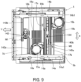
- Figure 9 is a view seeing through an upper surface of the feed tray 5 in Figure 8 .
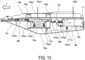
- Figure 10 is a cross-sectional view illustrating a cross section X-X of Figure 8 .
- the blowing fans 15a and 15b are disposed below the stacking surface 5a of the feed tray 5.
- the blowing fans 15a and 15b are disposed on an opposite side to a side where the sheet is stacked on the stacking surface 5a.
- the air blowing fan is protruding to an outside of the feed tray 5 with respect to the sheet widthwise direction X, etc., which increases a space occupied by the manual feeding portion 235, and this in turn leads to a larger size of the image forming apparatus.
- the air blowing fans 15a and 15b are disposed in a space on the lower side of the stacking surface 5a of the feed tray 5, which can save space of the manual feeding portion 235, and it becomes possible for the image forming apparatus to be downsized.
- the blowing fans 15a and 15b are not protruded in the upper side of the feed tray 5, accessibility to the feed tray 5 is improved and thereby improving usability, and it is also advantageous in terms of noise reduction.
- blowing fans 15a and 15b are disposed so that at least a part of the blowing fans 15a and 15b is overlapped with the stacking surface 5a of the feed tray 5 as viewed from above ( Figure 3 ).
- each of the blowing fans 15a and 15b is disposed at a position overlapped with the stacking surface 5a, respectively.
- the blowing fan 15a is disposed so that a position of at least a part of the blowing fan 15a with respect to the sheet widthwise direction X is overlapped with a position of the stacking surface 5a with respect to the sheet widthwise direction X.
- the blowing fan 15b is disposed so that a position of at least a part of the blowing fan 15b with respect to the sheet widthwise direction X is overlapped with the position of the stacking surface 5a with respect to the sheet widthwise direction X.
- the stacking surface 5a (sheet stacking region) of the feed tray 5 is defined as a region where the sheet Sa of the largest size among the sheets that can be fed from the manual feeding portion 235 is stacked on the upper surface of the feed tray 5.
- the stacking surface 5a of the feed tray 5 is the sheet stacking region where the sheet Sa is stacked in a state in which the side end guides 14a and 14b are widened to the outermost with respect to the sheet widthwise direction X ( Figure 6 ). Therefore, a region where the sheet Sb is stacked in a state in which the side end guides 14a and 14b are narrowed to the innermost with respect to the sheet widthwise direction X ( Figure 7 ) is a part of the stacking surface 5a in the present Embodiment, and is completely included by the stacking surface 5a. In other words, even in a state of Figure 7 , the stacking surface 5a of the feed tray 5 is still in a region within a width of the sheet Sa of the largest size indicated by a single-dotted line in Figure 7 .
- a part of the blowing fan 15a with respect to the sheet widthwise direction X may overlap a position of the stacking surface 5a with respect to the sheet widthwise direction X, or an entire blowing fan 15a with respect to the sheet widthwise direction X may overlap a position of the stacking surface 5a with respect to the sheet widthwise direction X.
- blowing fans 15a and 15b are accommodated inside a housing of the feed tray 5. That is, it is preferable for the blowing fans 15a and 15b to be accommodated in an inner space of the feed tray 5 expanding between the stacking surface 5a (upper surface) and a bottom surface 5b of the feed tray 5 as shown in Figure 10 . According to this configuration, since the blowing fans 15a and 15b are not exposed to the outside, it has the advantages such as improved safety, aesthetics in appearance, noise reduction.
- the feed tray 5 is openable and closable with respect to the main assembly 201A without concerning about interference between the blowing fans 15a and 15b and the main assembly 201A. Therefore, compared to a case where a space to receive the blowing fans 15a and 15b is secured for when the feed tray 5 is closed to the main assembly 201A, for example, it has the advantages such as downsizing of the apparatus and improving design freedom.
- the blowing fan 15a is attached to the side end guide 14a, which is movable in the sheet widthwise direction X with respect to the feed tray 5, and moves integrally with the side end guide 14a.
- the blowing fan 15b is attached to the side end guide 14b, which is movable in the sheet widthwise direction X with respect to the feed tray 5, and moves integrally with the side end guide 14b.
- a sucking inlet is provided ( Figure 9 ).
- the bottom surface 5b of the feed tray 5 is provided with sucking inlets 19a and 19b lined with a plurality of slits extending in the sheet widthwise direction X.
- the sucking inlets 19a and 19b may have lengths so that a state that at least a part of an opening 15a2 of a suction side of the blowing fan ( Figure 10 ) is opposite to the sucking inlets 19a and 19b is maintained in a case in which the side end guides 14a and 14b move from one end of a moving range to the other end.
- the lengths of the sucking inlets 19a and 19b in the sheet widthwise direction X may be longer than a diameter of the opening 15a2 ( Figure 10 ) on the suction side of the blowing fans 15a and 15b.
- the blowing fan 15a on the front side sucks air (outside air) from the outside of the feed tray 5 via the sucking inlet 19a (stream line E1).
- a duct 141a is formed inside the side end guide 14a.
- the air exhausted from the blowing fan 15a (stream line D1) is led to the blowing outlets 16a by the duct 141a.
- the duct 141a extends in the feeding direction Y inside the side end guide 14a so that the air is distributed to two blowing outlets 16a (first blowing outlet and second blowing outlet) by the duct 141a (stream line B1). And the air is blown from the blowing outlets 16a to the side end of the sheet S toward the inside of the sheet widthwise direction X (stream line A1, see also Figure 3 ).
- the air path on the rear side is the same as that on the front side except that a position of the blowing fan 15b is different. That is, the blowing fan 15b sucks air (outside air) from the outside of the feed tray 5 via the sucking inlet 19b (stream line E1).
- a duct 141b is formed inside the side end guide 14b.
- the air exhausted from the blowing fan 15b (stream line D1) is led to the blowing outlets 16b by the duct 141b.
- the duct 141b extends in the feeding direction Y inside the side end guide 14b so that air is distributed to two blowing outlets 16b by the duct 141b (stream line B1 and C1). And the air is blown from the blowing outlets 16b to the side end of the sheet S toward the inside of the sheet widthwise direction X (stream line A2 in Figure 3 ).
- an exhausting direction of the blowing fan 15a and a blowing direction of the air from the blowing outlets 16a are disposed in opposite directions with respect to the sheet widthwise direction X. That is, the blower fan 15a is disposed to exhaust air outside with respect to the sheet widthwise direction X (stream line F1). The blowing outlets 16a are disposed to blow the air inside with respect to the sheet widthwise direction X (stream line A1).
- the blowing fan 15a is disposed by utilizing the space inside the sheet widthwise direction X with respect to the side end guide 14a.
- an entire rotary blade which is a main body portion of the blowing fan 15a, to be positioned inside the regulating surface 14a1 with respect to the sheet widthwise direction X.
- Figure 5 illustrates an arrangement of the blowing fan 15a on the front side, but the same is true for the blowing fan 15b on the rear side except that a positioning is reversed with respect to the sheet widthwise direction X. That is, as viewed in the feeding direction Y, an exhausting direction of the blowing fan 15b and a blowing direction of the air from the blowing outlets 16b are disposed in opposite directions with respect to the sheet widthwise direction X (see Figure 3 ). By this configuration, it becomes possible to save the space of the manual feeding portion 235 with respect to the sheet widthwise direction X.
- a sirocco fan which is a type of a centrifugal fan, is used as the blowing fans 15a and 15b, and rotation axes 15a1 and 15b1 of the rotary blades are disposed so as to be crossed with the stacking surface 5a of the feed tray 5. It is preferable that the rotation axes 15a1 and 15b1 are disposed so as to be substantially perpendicular to the stacking surface 5a (substantially parallel to a normal direction Z of the stacking surface 5a). By this, it become possible to downsize the feed tray 5 with respect to a thickness direction.
- a centrifugal fan is a fan that sucks air from one side of the rotary blades in an axial direction and exhausts in a direction perpendicular to the axial direction (centrifugal direction), and is, for example, the sirocco fan or a turbo fan.
- the sirocco fan is superior in terms of satisfying quietness, durability, and static pressure required for a sheet separation, etc., in a well-balanced manner.
- a centrifugal fan other than the sirocco fan or an axial fan can also be used, however, as the blowing fan.
- the duct 141a penetrates the upper side of the feed tray 5 from the lower side to the upper side so as to connect the blowing fan 15a, which is disposed below the stacking surface 5a of the feed tray 5, with the blowing outlets 16a, which is disposed above the stacking surface 5a.
- the duct 141b on the rear side. Therefore, as shown in Figure 8 , notches 5d (slits, opening portions) that permit movements of the ducts 141a and 141b in the sheet widthwise direction X along movements of the side end guides 14a and 14b are formed in the stacking surface 5a.
- a position and a shape of the notches 5d may be varied to match the ducts 141a and 141b. Besides this, notches through which a portion of the side end guides 14a and 14b penetrate vertically is also formed near an interrelating mechanism M1 (described below) in the stacking surface 5a.
- the side end guides 14a and 14b are connected to each other by the interrelating mechanisms M1 and M2 inside the feed tray 5.
- a rack and pinion mechanism constituted by racks 143a and 143b and a pinion gear 142 is used as the interrelating mechanism M1.
- a rack and pinion mechanism constituted by racks 145a and 145b and a pinion gear 144 is used as the interrelating mechanism M2.
- the blowing fans 15a and 15b which move integrally with the side end guides 14a and 14b, are disposed inside in the sheet widthwise direction X with respect to the side end guides 14a and 14b. By this, it becomes possible to downsize the manual feeding portion 235 in the sheet widthwise direction X.
- the blowing fan 15a (first blowing fan) is different in a position with respect to the feeding direction Y from the blowing fan 15b (second blowing fan).
- the blowing fans 15a and 15b are guided by slide shafts 17a and 17b held by the feed tray 5, respectively.
- the slide shafts 17a and 17b are shaft-shaped members extending in the sheet widthwise direction X.
- the blowing fan 15a is provided with a fitting portion 15a3 fitting with the slide shaft 17a.
- the blowing fan 15b is provided with a fitting portion 15b3 fitting with the slide shaft 17b.
- a position of the operating knob 18 provided on the side end guide 14a in the feeding direction Y and a position of the slide shaft 17a in the feeding direction Y may be overlapped. By this, it becomes less likely for a force in a rotational direction to be exerted to the side end guide with respect to the slide shaft 17a when the side end guide 14a is moved, thereby facilitating a smooth movement of the side end guide 14a and improving operability.
- the rotation axis 15a1 of the blowing fan 15a of the front side is disposed near the blowing outlet 16a
- the rotation axis 15b1 of the blowing fan 15b of the rear side is disposed upstream in the feeding direction Y away from the blowing outlet 16b of the side end guide 14b.
- the blowing fan 15b is disposed in a direction such that an exhaust port 15b2 is positioned downstream side of the feeding direction Y with respect to the rotation axis 15b 1.
- a door 601 which is an opening/closing member for carrying out a jam clearing process of the cassette feeding portion 230 ( Figure 1 ), is disposed below the manual feeding portion 235.
- the door 601 is supported by a hinge 602 on the main assembly 201A of the image forming apparatus 201 ( Figure 1 ), and can rotate about a rotation axis extending in the sheet widthwise direction X.
- a locus 603 in the figure is a locus drawn by a tip of the door 601 (end portion of farther side from the hinge 602) when the door 601 is opened and closed.
- the bottom surface 5b of the feed tray 5 is provided with an inclined portion 5c formed in a tapered shape so as to become closer to the stacking surface 5a as it goes downstream in the feeding direction Y (see also Figure 10 ).
- the blowing fans 15a and 15b having some thickness to be accommodated inside the feed tray 5 and to avoid interference with the door 601.
- the blowing fan 15b may be disposed at a position that overlaps the locus 603 as viewed in the sheet widthwise direction X but is different from the tip of the door 601 with respect to the sheet widthwise direction X.
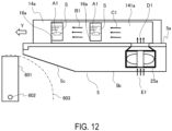
- FIG. 11 is a schematic view of the manual feeding portion 235 according to the present Embodiment as viewed from above.
- Figure 12 is a cross section XII-XII of Figure 11 .
- elements with common reference letters with the Embodiment 1 have substantially the same configurations and actions as those described in the Embodiment 1.
- the present Embodiment differs from the Embodiment 1 in a point that an axial fan, which is relatively low cost, is used as the blowing fans 25a and 25b.
- the present Embodiment differs from the Embodiment 1 in a point that the blowing fans 25a and 25b are disposed near the end portion of the upstream side of the feed tray 5 with respect to the feeding direction Y, and the positions of the blowing fans 25a and 25b are overlapped as viewed in the sheet widthwise direction X.
- the blowing fans 25a and 25b are disposed so that the rotation axis of the rotary blades (propeller) is crossed with the stacking surface 5a of the feed tray 5 (preferably, so as to be substantially parallel to the normal direction of the stacking surface 5a). Therefore, the blowing fans 25a and 25b suck outside air from below the feed tray 5 (stream line E1) and exhaust above toward the ducts 141a and 141b (stream line D1), respectively. And the air passes through the inside of the ducts 141a and 141b and is blown from the blowing outlets 16a and 16b to the side ends of the sheets.
- both blowing fans 25a and 25b are disposed below the stacking surface 5a of the feed tray 5 as the stacking member. Therefore, also by the present Embodiment, it becomes possible to save space in the configuration that blows air to the sheets.
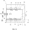
- FIG. 13 is a schematic view of the manual feeding portion 235 according to the present Embodiment as viewed from above.
- Figure 14 is a cross section XIV-XIV of Figure 13 .
- elements with common reference letters with the Embodiment 1 have substantially the same configurations and actions as those described in the Embodiment 1.
- blowing fans 35a and 35b sirocco fans with comparatively large air volume and yet with quietness and durability are used as blowing fans 35a and 35b.
- the present Embodiment differs from the Embodiment 1 in points that the blowing fans 35a and 35b are disposed near the end portion of the upstream side of the feed tray 5 with respect to the feeding direction Y, and the positions of the blowing fans 35a and 35b are overlapped as viewed in the sheet widthwise direction X.
- the blowing fans 35a and 35b are disposed so that the rotation axis of the rotary blades (propeller) is crossed with the stacking surface 5a of the feed tray 5 (preferably, so as to be substantially parallel to the normal direction of the stacking surface 5a).
- the blowing fans 35a and 35b suck outside air from below the feed tray 5 (stream line E1) and exhaust in a direction along the stacking surface 5a.
- the ducts 141a and 141b are provided with curved portions Cv that guide the air exhausted from the blowing fans 35a and 35b in a direction along the stacking surface Sa toward above the stacking surface 5a, respectively.
- the air guided by the curved portions Cv (stream D1) passes through the inside of the ducts 141a and 141b and is blown from the blowing outlets 16a and 16b to the side ends of the sheets.
- both blowing fans 35a and 35b are disposed below the stacking surface 5a of the feed tray 5 as the stacking member. Therefore, also by the present Embodiment, it becomes possible to save space in the configuration that blows air to the sheets.
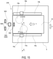
- FIG. 15 is a schematic view of the manual feeding portion 235 according to the present Embodiment as viewed from above.
- elements with common reference letters with the Embodiment 1 have substantially the same configurations and actions as those described in the Embodiment 1.
- the present Embodiment differs from the Embodiment 1 in a point that the blowing fans 15a and 15b are disposed so as to be facing each other in the sheet widthwise direction X.
- a cross-sectional view with respect to a cross section A-A of Figure 15 is the same as Figure 5 of the Embodiment 1.
- the side end guide 14a is provided with the one blowing outlet 16a and the side end guide 14b is provided with the one blowing outlet 16b.
- FIG. 16 is a schematic view illustrating a cross section sectioned the manual feeding portion 235 according to the present Embodiment with a plane perpendicular to the feeding direction Y
- elements with common reference letters with the Embodiment 1 have substantially the same configurations and actions as those described in the Embodiment 1.
- an axial fan is used as the blowing fan 25a, and the blowing fan 25a is disposed so that the rotation axis of the rotary blades (propeller) is along the sheet widthwise direction X (direction substantially perpendicular to the regulating surface 14a1 of the side end guide 14a).
- the blowing fan 25a sucks air from inside with respect to the sheet widthwise direction X (stream line D1) and exhausts toward outside with respect to the sheet widthwise direction X (stream line B1).
- the air from the blowing fan 25a is blown, through the inside of the duct 141a, to the side end of the sheet from the blowing outlet 16a (stream line A1). Therefore, an exhausting direction of the blowing fan 25a and a blowing direction of the air from the blowing outlet 16a are opposite with respect to the sheet widthwise direction X. Therefore, also by this configuration, it becomes possible to save space in the sheet widthwise direction X.
- an occupied width of the blowing fan in the sheet widthwise direction X it becomes possible for an occupied width of the blowing fan in the sheet widthwise direction X to be smaller than in cases where the blowing fan is disposed so that the rotation axis of the blowing fan is perpendicular to the stacking surface 5a of the feed tray 5. Therefore, it becomes possible to deal with the sheet having a narrower width by disposing the side end guides 14a and 14b closer to each other in the sheet widthwise direction X.
- the blowing fan 25a is disposed below the stacking surface 5a of the feed tray 5 as the stacking member. Therefore, also by the present Embodiment, it becomes possible to save space in the configuration that blows air to the sheets.
- blowing fan 25a can be disposed in the same arrangement on the other side end guide 14b.
- FIG. 17 is a schematic view illustrating a cross section sectioned the manual feeding portion 235 according to the present Embodiment with a plane perpendicular to the feeding direction Y
- elements with common reference letters with the Embodiment 1 have substantially the same configurations and actions as those described in the Embodiment 1.
- a sirocco fan is used as the blowing fan 35a and a position of the blowing fan 35a is fixed to the feed tray 5.
- An exhaust port of the blowing fan 35a is connected to the duct 141a disposed to the side end guide 14a via an extension/contraction duct 36a that can be extended and contracted in the sheet widthwise direction X.
- the blowing fan 35a sucks air from below (stream line D1) and exhausts toward outside with respect to the sheet widthwise direction X.
- the air from the blowing fan 35a is blown, through the inside of the extension/contraction duct 36a and the duct 141a (stream line B1), to the side end of the sheets from the blowing outlet 16a (stream line A1). Therefore, an exhausting direction of the blowing fan 35a and a blowing direction of the air from the blowing outlet 16a are opposite with respect to the sheet widthwise direction X. Therefore, also by this configuration, it becomes possible to save space in the sheet widthwise direction X.
- an axial fan may be fixed to the feed tray 5.
- the one side end guide 14a is provided with the two blowing outlets 16a.
- An amount of the air blown from each of the blowing outlets 16a may be equal, or the amount of the one may be larger than that of the other.
- an air blowing may be turned ON or OFF according to the type and the size of the sheet. For example, only in cases where the size of the sheet is larger than a predetermined size, the blowing fan may be actuated and the air blowing may be turned ON.
- a number of blowing outlets 16a may be one per the side end guide 14a, or three or more per the side end guide 14a.
- blowing fans corresponding to each of the pair of the side end guides 14a and 14b are described as examples. Not limited to this, the blowing fan may be disposed on only one side of the side end guides.
- the manual sheet feed apparatus disposed in a side surface portion of the image forming apparatus used mainly in an office is described.
- the present art may be applied to the cassette feeding portion 230 ( Figure 1 ).
- the present art may be applied to a sheet feed apparatus of a manual feed type or a sheet feed apparatus used with connecting to the main assembly of the image forming apparatus (optional feeder) in a larger image forming apparatus for commercial use.
- An image forming apparatus includes an image forming portion, a tray rotatably provided on a side surface of a main assembly and including a stacking surface, a feeding portion; and a blowing fan mounted on the tray and generating air blown to a side end of a sheet in a sheet widthwise direction perpendicular to a feeding direction of the sheet by the feeding portion.
- the blowing fan is disposed on an opposite side to a side where the sheet is stacked on the stacking surface so that a position of at least a part of the blowing fan with respect to the sheet widthwise direction is overlapped with a position of the stacking surface with respect to the sheet widthwise direction.
Landscapes
- Engineering & Computer Science (AREA)
- Mechanical Engineering (AREA)
- Physics & Mathematics (AREA)
- General Physics & Mathematics (AREA)
- Sheets, Magazines, And Separation Thereof (AREA)
Abstract
Description
- The present invention relates to an image forming apparatus forming an image on a sheet.
- In recent years, it is increasingly demanded even for an electrophotographic image forming apparatuses used in offices to produce high-quality and high image quality results using special papers such as a coated paper and a thick paper. However, because of a reason that these special papers have a high smoothness of a surface and a sticking is likely to occur between the sheets, etc., it is more difficult to separate and feed sheets one by one from a sheet bundle in a state of stacking than an ordinary plain paper or a recycled paper for office use.
-
Japanese Patent Laid-open No. 2006-256819 - The present invention makes possible to save space in a configuration that blows air to the sheet.
- One aspect of the present invention is an image forming apparatus comprising, an image forming portion configured to form an image on a sheet, a tray rotatably provided on a side surface of a main assembly accommodating the image forming portion and including a stacking surface on which the sheet is stacked, a feeding portion configured to feed the sheet stacked on the stacking surface toward the image forming portion, and a blowing fan mounted on the tray and configured to generate air blown to a side end of the sheet with respect to a sheet widthwise direction perpendicular to a feeding direction of the sheet by the feeding portion, wherein the blowing fan is disposed on an opposite side to a side where the sheet is stacked on the stacking surface so that a position of at least a part of the blowing fan with respect to the sheet widthwise direction is overlapped with a position of the stacking surface with respect to the sheet widthwise direction.
- Further features of the present invention will become apparent from the following description of exemplary embodiments with reference to the attached drawings.
-
-
Figure 1 is a schematic view of an image forming apparatus according to anEmbodiment 1. -
Figure 2 is a block diagram illustrating a control system of the image forming apparatus according to theEmbodiment 1. -
Figure 3 is a schematic view of a manual feeding portion according to theEmbodiment 1 as viewed from above. -
Figure 4 , part(a) and (b), is a schematic view illustrating cross sections of the manual feeding portion according to theEmbodiment 1. -
Figure 5 is a schematic view illustrating a cross section of the manual feeding portion according to theEmbodiment 1. -
Figure 6 is a schematic view of the manual feeding portion according to theEmbodiment 1 as viewed from above. -
Figure 7 is a schematic view of the manual feeding portion according to theEmbodiment 1 as viewed from above. -
Figure 8 is a detail view of the manual feeding portion according to theEmbodiment 1 as viewed from above. -
Figure 9 is a detail view illustrating an inside of a feed tray according to theEmbodiment 1. -
Figure 10 is a detail view illustrating a cross section of the manual feeding portion according to theEmbodiment 1. -
Figure 11 is a schematic view of a manual feeding portion according to an Embodiment 2 as viewed from above. -
Figure 12 is a schematic view illustrating a cross section of the manual feeding portion according to the Embodiment 2. -
Figure 13 is a schematic view of a manual feeding portion according to anEmbodiment 3 as viewed from above. -
Figure 14 is a schematic view illustrating a cross section of the manual feeding portion according to theEmbodiment 3. -
Figure 15 is a schematic view of a manual feeding portion according to an Embodiment 4 as viewed from above. -
Figure 16 is a schematic view illustrating a cross section of a manual feeding portion according to anEmbodiment 5. -
Figure 17 is a schematic view illustrating a cross section of a manual feeding portion according to an Embodiment 6. -
Figure 18 is a schematic view of the image forming apparatus according to theEmbodiment 1. - Hereinafter, Embodiments according to the present disclosure will be described with reference to the drawings.
- In the present disclosure, an "image forming apparatus" refers to an apparatus forming an image on a sheet as a recording material. The image forming apparatus includes a printer, a copy machine, a multifunctional machine, a commercial printing machine, etc.
-
Figure 1 is a cross-sectional view illustrating a schematic configuration of animage forming apparatus 201 according to an embodiment (Embodiment 1). Theimage forming apparatus 201 is a laser beam printer of a tandem-type and of an intermediate transfer method using an electrophotographic image forming process. Theimage forming apparatus 201 can form and output a full-color or a single-color image on a sheet S based on image data. As the sheet S, a variety of sheets of different sizes and materials may be used, including a plain paper and a thick paper, a plastic film, a cloth, a sheet material with a surface treatment such as a coated paper, a sheet material having a special shape such as an envelope and an index paper. - As shown in
Figure 1 , theimage forming apparatus 201 is provided with amain assembly 201A accommodating animage forming portion 201B, animage reading apparatus 202 disposed above themain assembly 201A reading image information from a document, and acontrol portion 100 controlling an entire apparatus operation (Figure 2 ). Theimage forming portion 201B which is an example of an image forming portion, includes four process units PY, PM, PC, and PK, anexposure device 210, atransfer belt 216, and afixing device 201E. A discharge space V for discharging the sheets is formed between theimage reading apparatus 202 and themain assembly 201A. - Each process unit PY, PM, PC and PK includes a
photosensitive drum 212 as an image bearing member, acharging device 213 as a process portion acting on thephotosensitive drum 212, a developingdevice 214, a cleaning device, etc. Thephotosensitive drum 212 is an electrophotographic photosensitive member formed in a drum shaped. The developingdevice 214 accommodates either of a yellow, a magenta, a cyan, or a black toner as a developer. Theexposure device 210 as the process portion (exposure portion) is disposed below the process units PY, PM, PC, and PK. - The
transfer belt 216 is an example of an intermediary transfer member. Thetransfer belt 216 is wound around adrive roller 216a and atension roller 216b. Inside thetransfer belt 216, fourprimary transfer rollers 219 are disposed at a position opposite to the correspondingphotosensitive drums 212 across thetransfer belt 216, respectively. Thetransfer belt 216 is rotated in a counterclockwise direction as shown in an arrow in the figure by adrive roller 216a driven by a drive portion not shown. Outside thetransfer belt 216, asecondary transfer roller 217 is disposed at a position, opposite to thedrive roller 216a across thetransfer belt 216. Atransfer portion 201D (secondary transfer portion) is formed as a nip portion between thesecondary transfer roller 217 and thetransfer belt 216. - A
fixing device 201E is disposed above thetransfer portion 201D. Thefixing device 201E is a thermal fixing method provided with aheating roller 220b heated by a heating portion such as a halogen lamp, and apressing roller 220a being pressurized against theheating roller 220b. Further above thefixing device 201E, a firstdischarge roller pair 225a, a seconddischarge roller pair 225b, and a double-sidedreversing portion 201F are disposed. The double-sidedreversing portion 201F includes a reversingroller pair 222 which can be rotated in a forward direction and a reverse direction and a reconveyance path R. - At an upper portion of the
image forming apparatus 201, anoperating portion 730 receiving operations from a user is disposed. Theoperating portion 730 includes a display device such as a liquid crystal panel displaying images, and an input device such as a numeric keypad and a printing execution button. For example, the user can input setting information (type, basis weight, size, brand name, etc.) of the sheet S set in acassette feeding portion 230 and amanual feeding portion 235 via theoperating portion 730. - The
cassette feeding portion 230 is disposed at a lower portion of themain assembly 201A. Themanual feeding portion 235 is disposed at a side surface portion of themain assembly 201A. Thecassette feeding portion 230 and themanual feeding portion 235 are an example of a sheet feeding device feeding the sheet. - The
cassette feeding portion 230 is provided with acassette 1 as a sheet accommodating portion accommodating the sheet S and a pickup roller 2 as a feeding portion feeding the sheet S from thecassette 1. In addition, thecassette feeding portion 230 is provided with a separating roller pair constituted by afeed roller 3 and a retard roller 4 as a separation conveyance portion for separating the sheet S fed from the pickup roller 2. The retard roller 4 applies a frictional force to the sheet S in a nip portion between the retard roller 4 and thefeed roller 3 in an opposite direction to a feeding direction, thereby permitting only a single sheet S in contact with thefeed roller 3 to pass through the nip portion. -
Figure 2 is a block diagram illustrating a system configuration of theimage forming apparatus 201. Acontrol portion 100 is a control portion controlling operations of theimage forming apparatus 201 comprehensively and transfers information to and from ahost device 900 and the operatingportion 730. In addition, thecontrol portion 100 controls operations of theimage forming portion 201B, and of a feeding and a conveyance of the sheets, etc. Here, thehost device 900 is a personal computer, an image scanner, a facsimile, etc. Astorage portion 101 stores programs executed by thecontrol portion 100 and data necessary to execute the programs. In addition, thestorage portion 101 provides a workspace when thecontrol portion 100 executes the program. - The
control portion 100 controls operations of theimage forming apparatus 201 based on the setting information entered by the user via the operatingportion 730 and the image data received from thehost device 900. For example, thecontrol portion 100 controls a sheet feeding operation by driving an actuator (motor, etc.) of themanual feeding portion 235. In addition, thecontrol portion 100actuates blowing fans control portion 100 determines that a separation by blowing air is necessary based on the setting information of the sheet (e.g., in cases of the coated paper). - The control portion of the
image forming apparatus 201 starts an image forming operation when the control portion receives the image data from the external device or receives the image data read from a document by theimage reading apparatus 202 as an execution instruction of a copying operation is given. In the image forming operation, each of the process units PY, PM, PC, and PK forms a toner image on a surface of thephotosensitive drum 212 by an electrophotographic process. That is, when a formation of the toner image is requested to the process units PY, PM, PC, and PK, thephotosensitive drum 212 is driven and rotated, and thecharging device 213 uniformly charges the surface of thephotosensitive drum 212. Theexposure device 210 irradiates a laser beam onto thephotosensitive drum 212 based on the image data received from the outside by the control portion or the image data read from the document by theimage reading apparatus 202. As a result, the surface ofphotosensitive drum 212 is exposed and an electrostatic latent image is formed. The developingdevice 214 supplies the developer containing the toner to thephotosensitive drum 212 and develops the electrostatic latent image into the toner image. - The toner images formed by the process units PY, PM, PC, and PK are primarily transferred to the
transfer belt 216 by theprimary transfer roller 219. When forming a full-color image, the primary transfer is performed so that the toner images of each color overlap on thetransfer belt 216, and thereby forming a color image on thetransfer belt 216. Adhesive materials such as the toner remaining on the photosensitive drum 151 is removed by the cleaning device of each of the process units PY, PM, PC, and PK. - In parallel with the operation of the
image forming portion 201B, the sheets S are fed one by one from thecassette feeding portion 230 or themanual feeding portion 235 and conveyed to aregistration roller pair 240. After correcting an oblique movement of the sheet S, theregistration roller pair 240 conveys the sheet S to thetransfer portion 201D at a timing synchronized with the operation of theimage forming portion 201B. And in thetransfer portion 201D, the toner image is secondarily transferred from thetransfer belt 216 to the sheet S by thesecondary transfer roller 217 to which transfer voltage is applied. - The sheet S that has passed through the
transfer portion 201D is conveyed to thefixing device 201E. The fixingdevice 201E heats and pressurizes the toner image on the sheet S while nipping and conveying the sheet S between theheating roller 220b and thepressing roller 220a. By this, a fixed image is produced on the sheet S. Incidentally, a sticking force to theheating roller 220b is generated on the sheet S due to an adhesive force of the melted toner. If a stiffness of the sheet S is low (weak), the sheet S may be wound around therotating heating roller 220b, therefore a separatingplate 221 is disposed at a downstream side of theheating roller 220b to separate the sheet. - In a case of a single-side printing, the sheet S that has passed through the
fixing device 201E is discharged into the discharge space V by the firstdischarge roller pair 225a or the seconddischarge roller pair 225b, and is stacked on adischarge tray 223. In a case of a double-side printing, the sheet S of which the image is formed on a first side by passing through thetransfer portion 201D and thefixing device 201E is reversed by the reversingroller pair 222 and conveyed again to theimage forming portion 201B via the reconveyance path R. And the sheet S on which an image is formed on a second side by passing through thetransfer portion 201D and thefixing device 201E again is discharged into the discharge space V by the firstdischarge roller pair 225a or the seconddischarge roller pair 225b, and is stacked on thedischarge tray 223. - In the above description, the
image forming portion 201B is an example of an image forming portion and instead of theimage forming portion 201B, an electrophotographic unit of a direct transfer method or an image forming unit of an inkjet method or of an offset printing method may be used. - The
manual feeding portion 235 provided with an air blowing portion will be described usingFigure 3. Figure 3 is a schematic view of themanual feeding portion 235 as viewed from above. Unlike thecassette feeding portion 230 which can accommodate a large number of the sheets, themanual feeding portion 235 is configured so that the user sets a necessary amount of the sheets when using theimage forming apparatus 201. Therefore, thecassette feeding cassette 230 is suitable for using sheets of a plain paper with a standard size which are frequently used, while themanual feeding portion 235 is suitable for using sheets such as the coated paper and a long sheet which are less frequently used. - In the description below, a "feeding direction Y" represents a direction in which sheets are fed from a
feed tray 5 by apickup roller 502. A "sheet widthwise direction X" represents a direction which is along the sheet stacked on thefeed tray 5 and is perpendicular to the feeding direction Y - The
manual feeding portion 235 is provided with thefeed tray 5, thepickup roller 502, afeed roller 503, aretard roller 504, aside end guide 14a and aside end guide 14b, and a blowingfan 15a and a blowingfan 15b. - The
feed tray 5 is a tray (stacking member) on which sheets are stacked. Thefeed tray 5 includes a stackingsurface 5a (a support surface supporting a lower surface of a sheet, a mounting surface) on which a sheet is stacked. Thefeed tray 5 can be rotated (openable and closable), with asupport portion 5e (hinge portion) as a rotational center, between an accommodated position (seeFigure 18 ) in which thefeed tray 5 is accommodated in the side surface portion of themain assembly 201A of theimage forming apparatus 201 and a feeding position in which thefeed tray 5 is protruding outside themain assembly 201A and capable of feeding the sheets. In a state where thefeed tray 5 is opened, the user can set the sheets onto thefeed tray 5. Thefeed tray 5 is also called as a manual feed tray or a multi-purpose tray. - The
pickup roller 502 is an example of a feeding portion feeding the sheets. Thepickup roller 502 is disposed above the stackingsurface 5a of thefeed tray 5. Thepickup roller 502 is rotatably supported by a roller holder as a holding member. The roller holder is swingable about a rotation axis of thefeed roller 503. As the roller holder swings, thepickup roller 502 moves between a feeding position (contact position, lower position) where thepickup roller 502 contacts an upper surface of the sheet stacked on thefeed tray 5, and a standby position (separation position, upper position) where thepickup roller 502 is separated above from the sheet. The sheet is fed from thefeed tray 5 in the feeding direction Y as thepickup roller 502 rotates in the feeding position. Instead of thepickup roller 502, a mechanism conveying the sheet, for example, by adsorbing the sheet to a belt by a negative pressure generated by a fan and rotating the belt may be used. - The
feed roller 503 further conveys the sheet received from thepickup roller 502 in the feeding direction Y Aconveyance roller pair 506 is disposed downstream of thefeed roller 503 that conveys the sheet received from thefeed roller 503 toward the registration roller pair 240 (Figure 1 ). - The
retard roller 504 is pressurized against thefeed roller 503 and forms a separation nip between thefeed roller 503 and theretard roller 504. In addition, a driving force in a direction that goes against a rotation of thefeed roller 503 is inputted to theretard roller 504 via a torque limiter. Theretard roller 504 is an example of a separating member separating the sheet with a frictional force and instead of theretard roller 504, for example, a roller member connected to a fixed shaft via the torque limiter or a pad-shaped elastic member abutting thefeed roller 503 may be used. - The side end guides 14a and 14b are regulating members (regulating plates) regulating a position of the sheet with respect to the sheet widthwise direction X. In the present Embodiment, a pair of the side end guides 14a and 14b facing each other with respect to the sheet widthwise direction X is used. The
side end guide 14b of a rear side is a second side end guide disposed opposite to theside end guide 14a as a first side end guide with respect to the sheet widthwise direction X. The side end guides 14a and14b are provided with regulating surfaces 14a1 and14b 1 as inside surfaces with respect to the sheet widthwise direction X, respectively. An "inside" of the sheet widthwise direction X with respect to one of the side end guides is a side where the other of the side end guides is disposed and is a side where the sheet is stacked, and an "outside" of the sheet widthwise direction X is an opposite side to the side where the other of the side end guides is disposed. The regulating surfaces 14a1 and14b 1 are surfaces extending in the feeding direction Y and rising substantially perpendicular to thefeed tray 5 as viewed in the feeding direction Y The regulating surfaces 14a1 and14b 1 regulate the position of the sheet with respect to the sheet widthwise direction X by abutting end portions in the sheet widthwise direction X of the sheet (side ends of the sheet) stacked on thefeed tray 5. - The side end guides 14a and 14b are movable in the sheet widthwise direction X relative to the
feed tray 5. The side end guides 14a and 14b are connected by an interrelating mechanism such as a rack and pinion mechanism and move in interrelation with each other so that a distance from a center position X0 to each of the side end guides in the sheet widthwise direction X is the same. The center position X0 is a reference position in the sheet widthwise direction X of the sheets that themanual feeding portion 235 feeds. - One of the side end guides 14a and 14b (the
side end guide 14a on a front side of the image forming apparatus 201) is provided with an operatingknob 18 as an operating portion (gripping portion) for moving the side end guides 14a and 14b. The user can prevent the oblique movement and a misalignment of the sheet by moving the side end guides 14a and 14b to a position that matches the size of the sheet to be used. - The blowing
fans feed tray 5. The blowingfans feed tray 5 to generate an air flow. The blowingfans surface 5a of thefeed tray 5. The blowingfans - The side end guides 14a and 14b are provided with blowing
outlets fans feed tray 5, respectively. The blowingoutlets 14b 1 of the side end guides 14a and 14b, respectively. In addition, the blowingoutlets fans - When blowing
fans outlets - Incidentally, heights of the openings of the blowing
outlets feed tray 5, respectively. The maximum stacking height of the sheets is indicated, for example, by attaching a sticker indicating the maximum stacking height to at least one of the regulating surfaces 14a1 and14b 1 of the side end guides 14a and 14b. - In addition, in a case where it is varied whether an air blowing is performed or not depending on the type of the sheets, the maximum stacking height of the sheets (e.g., coated papers) to which the air blowing is performed may be set lower than the maximum stacking height of the sheets (e.g., plain papers) to which the air blowing is not performed. In addition, when the coated paper is selected at the operating
portion 730 by the user, a message to caution the user about the maximum stacking height may be displayed. - Next, the feeding operation in which the
manual feeding portion 235 feeds the sheets will be described with reference toFigure 2 . The user sets the sheets on thefeed tray 5 in advance and enters the setting information on the set sheets via the operatingportion 730. - When the user presses the printing execution button, the blowing
fans outlets manual feeding portion 235 can separate and feed the sheets one by one stably, even when using the sheets such as the coated papers, which have a high smoothness of a surface and between which a sticking is likely to occur. Incidentally, thecontrol portion 100 of theimage forming apparatus 201 may be configured to actuate the blowingfans - After a predetermined time elapses from a start of blowing air by the blowing
fans pickup roller 502 and thefeed roller 503, etc. are initiated, and thepickup roller 502 is moved from the standby position to the feeding position as the roller holder is swinged. Then, the topmost sheet that abuts thepickup roller 502 is fed to thefeed roller 503, separated from the other sheets in the separating nip to be conveyed further, and conveyed to the registration roller pair 240 (Figure 1 ) by theconveyance roller pair 506. The flows of the sheet conveyance and the image formation after this process are as described above. Incidentally, a timing of the conveyance of the sheet is monitored by a sheet sensor 505 (Figure 1 ) detecting the sheet at a position between thefeed roller 503 andconveyance roller pair 506. - Details of a configuration for blowing the air to the sheet in the present Embodiment will be described using
Figure 3 through Figure 10 below. -
Figure 3 is a schematic view of themanual feeding portion 235 as viewed from above.Figure 4(a) is a cross-sectional view illustrating a cross section IVA-IVA ofFigure 3 .Figure 4(b) is a cross-sectional view illustrating a cross section IVB-IVB ofFigure 3 .Figure 5 is a cross-sectional view illustrating a cross section V-V ofFigure 3 .Figure 6 is a schematic view illustrating a state in which the side end guides 14a and 14b are moved to the outermost position (a side end position of a sheet Sa of the largest size that can be fed from the manual feeding portion 235).Figure 7 is a schematic view illustrating a state in which the side end guides 14a and 14b are moved to the innermost position (a side end position of a sheet Sb of the smallest size that can be fed from the manual feeding portion 235).Figure 8 is a detail view of themanual feeding portion 235 as viewed from above.Figure 9 is a view seeing through an upper surface of thefeed tray 5 inFigure 8 .Figure 10 is a cross-sectional view illustrating a cross section X-X ofFigure 8 . - As shown in
Figure 4(a), Figure 4(b) andFigure 5 , the blowingfans surface 5a of thefeed tray 5. In other words, the blowingfans surface 5a. By this configuration, it becomes possible to save space in themanual feeding portion 235 provided with the air blowing configuration. In other words, when the blowingfan 15a is disposed on an upper side of the stackingsurface 5a, the blowing fan has to be disposed while avoiding the stackingsurface 5a. In this case, the air blowing fan is protruding to an outside of thefeed tray 5 with respect to the sheet widthwise direction X, etc., which increases a space occupied by themanual feeding portion 235, and this in turn leads to a larger size of the image forming apparatus. - In contrast, in the present Embodiment, since the
air blowing fans surface 5a of thefeed tray 5, which can save space of themanual feeding portion 235, and it becomes possible for the image forming apparatus to be downsized. In addition, since the blowingfans feed tray 5, accessibility to thefeed tray 5 is improved and thereby improving usability, and it is also advantageous in terms of noise reduction. - It is preferable for the blowing
fans fans surface 5a of thefeed tray 5 as viewed from above (Figure 3 ). With respect to the sheet widthwise direction X, each of the blowingfans surface 5a, respectively. In other words, the blowingfan 15a is disposed so that a position of at least a part of the blowingfan 15a with respect to the sheet widthwise direction X is overlapped with a position of the stackingsurface 5a with respect to the sheet widthwise direction X. Similarly, the blowingfan 15b is disposed so that a position of at least a part of the blowingfan 15b with respect to the sheet widthwise direction X is overlapped with the position of the stackingsurface 5a with respect to the sheet widthwise direction X. By this it becomes possible for the image forming apparatus to be downsized further. The stackingsurface 5a (sheet stacking region) of thefeed tray 5 is defined as a region where the sheet Sa of the largest size among the sheets that can be fed from themanual feeding portion 235 is stacked on the upper surface of thefeed tray 5. In other words, the stackingsurface 5a of thefeed tray 5 is the sheet stacking region where the sheet Sa is stacked in a state in which the side end guides 14a and 14b are widened to the outermost with respect to the sheet widthwise direction X (Figure 6 ). Therefore, a region where the sheet Sb is stacked in a state in which the side end guides 14a and 14b are narrowed to the innermost with respect to the sheet widthwise direction X (Figure 7 ) is a part of the stackingsurface 5a in the present Embodiment, and is completely included by the stackingsurface 5a. In other words, even in a state ofFigure 7 , the stackingsurface 5a of thefeed tray 5 is still in a region within a width of the sheet Sa of the largest size indicated by a single-dotted line inFigure 7 . - Incidentally, as shown in
Figure 6 , a part of the blowingfan 15a with respect to the sheet widthwise direction X may overlap a position of the stackingsurface 5a with respect to the sheet widthwise direction X, or anentire blowing fan 15a with respect to the sheet widthwise direction X may overlap a position of the stackingsurface 5a with respect to the sheet widthwise direction X. - It is preferable for the blowing
fans feed tray 5. That is, it is preferable for the blowingfans feed tray 5 expanding between the stackingsurface 5a (upper surface) and abottom surface 5b of thefeed tray 5 as shown inFigure 10 . According to this configuration, since the blowingfans feed tray 5 is openable and closable with respect to themain assembly 201A without concerning about interference between the blowingfans main assembly 201A. Therefore, compared to a case where a space to receive the blowingfans feed tray 5 is closed to themain assembly 201A, for example, it has the advantages such as downsizing of the apparatus and improving design freedom. - As shown in
Figure 3 ,Figure 6 andFigure 7 , the blowingfan 15a is attached to theside end guide 14a, which is movable in the sheet widthwise direction X with respect to thefeed tray 5, and moves integrally with theside end guide 14a. Similarly, the blowingfan 15b is attached to theside end guide 14b, which is movable in the sheet widthwise direction X with respect to thefeed tray 5, and moves integrally with theside end guide 14b. By configuring the blowingfans fans outlets - In a wall surface of the
feed tray 5 opposite to openings of a suction side of the blowingfans Figure 9 ). In the present Embodiment, thebottom surface 5b of thefeed tray 5 is provided with suckinginlets inlets Figure 10 ) is opposite to the suckinginlets fans inlets inlets Figure 10 ) on the suction side of the blowingfans - As shown in
Figure 4(a) , the blowingfan 15a on the front side sucks air (outside air) from the outside of thefeed tray 5 via the suckinginlet 19a (stream line E1). Aduct 141a is formed inside theside end guide 14a. The air exhausted from the blowingfan 15a (stream line D1) is led to the blowingoutlets 16a by theduct 141a. In the present Embodiment, theduct 141a extends in the feeding direction Y inside theside end guide 14a so that the air is distributed to two blowingoutlets 16a (first blowing outlet and second blowing outlet) by theduct 141a (stream line B1). And the air is blown from the blowingoutlets 16a to the side end of the sheet S toward the inside of the sheet widthwise direction X (stream line A1, see alsoFigure 3 ). - As shown in
Figure 4(b) , the air path on the rear side is the same as that on the front side except that a position of the blowingfan 15b is different. That is, the blowingfan 15b sucks air (outside air) from the outside of thefeed tray 5 via the suckinginlet 19b (stream line E1). Aduct 141b is formed inside theside end guide 14b. The air exhausted from the blowingfan 15b (stream line D1) is led to the blowingoutlets 16b by theduct 141b. In the present Embodiment, theduct 141b extends in the feeding direction Y inside theside end guide 14b so that air is distributed to two blowingoutlets 16b by theduct 141b (stream line B1 and C1). And the air is blown from the blowingoutlets 16b to the side end of the sheet S toward the inside of the sheet widthwise direction X (stream line A2 inFigure 3 ). - As shown in
Figure 5 , as viewed in the feeding direction Y, an exhausting direction of the blowingfan 15a and a blowing direction of the air from the blowingoutlets 16a are disposed in opposite directions with respect to the sheet widthwise direction X. That is, theblower fan 15a is disposed to exhaust air outside with respect to the sheet widthwise direction X (stream line F1). The blowingoutlets 16a are disposed to blow the air inside with respect to the sheet widthwise direction X (stream line A1). Thus, in the configuration where the blowingfan 15a is provided integrally with theside end guide 14a, the blowingfan 15a is disposed by utilizing the space inside the sheet widthwise direction X with respect to theside end guide 14a. By this configuration, it becomes possible to save space of themanual feeding portion 235 with respect to the sheet widthwise direction X. In addition, it is preferable for an entire rotary blade, which is a main body portion of the blowingfan 15a, to be positioned inside the regulating surface 14a1 with respect to the sheet widthwise direction X. - While
Figure 5 illustrates an arrangement of the blowingfan 15a on the front side, but the same is true for the blowingfan 15b on the rear side except that a positioning is reversed with respect to the sheet widthwise direction X. That is, as viewed in the feeding direction Y, an exhausting direction of the blowingfan 15b and a blowing direction of the air from the blowingoutlets 16b are disposed in opposite directions with respect to the sheet widthwise direction X (seeFigure 3 ). By this configuration, it becomes possible to save the space of themanual feeding portion 235 with respect to the sheet widthwise direction X. - As shown in
Figure 9 andFigure 10 , in the present Embodiment, a sirocco fan, which is a type of a centrifugal fan, is used as the blowingfans surface 5a of thefeed tray 5. It is preferable that the rotation axes 15a1 and 15b1 are disposed so as to be substantially perpendicular to the stackingsurface 5a (substantially parallel to a normal direction Z of the stackingsurface 5a). By this, it become possible to downsize thefeed tray 5 with respect to a thickness direction. - Incidentally, a centrifugal fan is a fan that sucks air from one side of the rotary blades in an axial direction and exhausts in a direction perpendicular to the axial direction (centrifugal direction), and is, for example, the sirocco fan or a turbo fan. Among centrifugal fans, the sirocco fan is superior in terms of satisfying quietness, durability, and static pressure required for a sheet separation, etc., in a well-balanced manner. A centrifugal fan other than the sirocco fan or an axial fan can also be used, however, as the blowing fan.
- By the way, as shown in
Figure 5 , theduct 141a penetrates the upper side of thefeed tray 5 from the lower side to the upper side so as to connect the blowingfan 15a, which is disposed below the stackingsurface 5a of thefeed tray 5, with the blowingoutlets 16a, which is disposed above the stackingsurface 5a. The same is true for theduct 141b on the rear side. Therefore, as shown inFigure 8 ,notches 5d (slits, opening portions) that permit movements of theducts surface 5a. A position and a shape of thenotches 5d may be varied to match theducts surface 5a. - A configuration with respect to the movement of the side end guides 14a and 14b and the blowing
fans fans Figure 6 andFigure 7 , the pair of the side end guides 14a and 14b move in interrelation with each other in the sheet widthwise direction X. - As shown in
Figure 9 , the side end guides 14a and 14b are connected to each other by the interrelating mechanisms M1 and M2 inside thefeed tray 5. In the present Embodiment, a rack and pinion mechanism constituted byracks pinion gear 142 is used as the interrelating mechanism M1. In addition, a rack and pinion mechanism constituted byracks pinion gear 144 is used as the interrelating mechanism M2. - As shown in
Figure 6 , the blowingfans manual feeding portion 235 in the sheet widthwise direction X. - In the present Embodiment, the blowing
fan 15a (first blowing fan) is different in a position with respect to the feeding direction Y from the blowingfan 15b (second blowing fan). By this, it becomes possible to make interference of the blowingfans - In particular, as shown in
Figure 7 , when the side end guides 14a and 14b are moved to a position matching the sheet Sb of the smallest size, positions of the blowingfans feed tray 5 effectively. - In addition, as shown in
Figure 7 , when the side end guides 14a and 14b are moved to the position matching the sheet Sb of the smallest size, theside end guide 14a on the front side overlaps the blowingfan 15b on the rear side as viewed from above. In addition, theside end guide 14b on the rear side overlaps the blowingfan 15a on the front side. In other words, in a state in which the first side end guide and the second side end guide are moved to the innermost position with respect to the sheet widthwise direction, the first side end guide and the second blowing fan are overlapped and the second side end guide and the first blowing fan are overlapped as viewed from above. By this, it becomes possible to deal with the sheet having a narrower width by utilizing the inner space of thefeed tray 5 effectively. - As shown in
Figure 6 ,Figure 7 andFigure 10 , the blowingfans slide shafts feed tray 5, respectively. Theslide shafts fan 15a is provided with a fitting portion 15a3 fitting with theslide shaft 17a. The blowingfan 15b is provided with a fitting portion 15b3 fitting with theslide shaft 17b. By this, weights of the blowingfans slide shafts - A position of the operating
knob 18 provided on theside end guide 14a in the feeding direction Y and a position of theslide shaft 17a in the feeding direction Y may be overlapped. By this, it becomes less likely for a force in a rotational direction to be exerted to the side end guide with respect to theslide shaft 17a when theside end guide 14a is moved, thereby facilitating a smooth movement of theside end guide 14a and improving operability. - By the way, as shown in
Figure 6 , while the rotation axis 15a1 of the blowingfan 15a of the front side is disposed near the blowingoutlet 16a, the rotation axis 15b1 of the blowingfan 15b of the rear side is disposed upstream in the feeding direction Y away from the blowingoutlet 16b of theside end guide 14b. In this case, the blowingfan 15b is disposed in a direction such that an exhaust port 15b2 is positioned downstream side of the feeding direction Y with respect to therotation axis 15bblowing outlet 16b and it becomes possible to blow air onto the sheet efficiently. - As shown in
Figure 4(a) and Figure 4(b) , below themanual feeding portion 235, adoor 601, which is an opening/closing member for carrying out a jam clearing process of the cassette feeding portion 230 (Figure 1 ), is disposed. Thedoor 601 is supported by ahinge 602 on themain assembly 201A of the image forming apparatus 201 (Figure 1 ), and can rotate about a rotation axis extending in the sheet widthwise direction X. Alocus 603 in the figure is a locus drawn by a tip of the door 601 (end portion of farther side from the hinge 602) when thedoor 601 is opened and closed. - In the present Embodiment, the
bottom surface 5b of thefeed tray 5 is provided with aninclined portion 5c formed in a tapered shape so as to become closer to the stackingsurface 5a as it goes downstream in the feeding direction Y (see alsoFigure 10 ). By this, it becomes possible for the blowingfans feed tray 5 and to avoid interference with thedoor 601. Incidentally, as long as interference with thedoor 601 can be avoided, for example, the blowingfan 15b may be disposed at a position that overlaps thelocus 603 as viewed in the sheet widthwise direction X but is different from the tip of thedoor 601 with respect to the sheet widthwise direction X. - A
manual feeding portion 235 according to an Embodiment 2 will be described usingFigure 11 andFigure 12 .Figure 11 is a schematic view of themanual feeding portion 235 according to the present Embodiment as viewed from above.Figure 12 is a cross section XII-XII ofFigure 11 . Hereinafter, elements with common reference letters with theEmbodiment 1 have substantially the same configurations and actions as those described in theEmbodiment 1. - The present Embodiment differs from the
Embodiment 1 in a point that an axial fan, which is relatively low cost, is used as the blowingfans Embodiment 1 in a point that the blowingfans feed tray 5 with respect to the feeding direction Y, and the positions of the blowingfans - The blowing
fans surface 5a of the feed tray 5 (preferably, so as to be substantially parallel to the normal direction of the stackingsurface 5a). Therefore, the blowingfans ducts ducts outlets - Also in the present Embodiment, both blowing
fans surface 5a of thefeed tray 5 as the stacking member. Therefore, also by the present Embodiment, it becomes possible to save space in the configuration that blows air to the sheets. - A
manual feeding portion 235 according to anEmbodiment 3 will be described usingFigure 13 andFigure 14 .Figure 13 is a schematic view of themanual feeding portion 235 according to the present Embodiment as viewed from above.Figure 14 is a cross section XIV-XIV ofFigure 13 . Hereinafter, elements with common reference letters with theEmbodiment 1 have substantially the same configurations and actions as those described in theEmbodiment 1. - In the present Embodiment, sirocco fans with comparatively large air volume and yet with quietness and durability are used as blowing
fans Embodiment 1 in points that the blowingfans feed tray 5 with respect to the feeding direction Y, and the positions of the blowingfans - The blowing
fans surface 5a of the feed tray 5 (preferably, so as to be substantially parallel to the normal direction of the stackingsurface 5a). The blowingfans surface 5a. Theducts fans surface 5a, respectively. The air guided by the curved portions Cv (stream D1) passes through the inside of theducts outlets - Also in the present Embodiment, both blowing
fans surface 5a of thefeed tray 5 as the stacking member. Therefore, also by the present Embodiment, it becomes possible to save space in the configuration that blows air to the sheets. - A
manual feeding portion 235 according to an Embodiment 4 is described usingFigure 15. Figure 15 is a schematic view of themanual feeding portion 235 according to the present Embodiment as viewed from above. Hereinafter, elements with common reference letters with theEmbodiment 1 have substantially the same configurations and actions as those described in theEmbodiment 1. - The present Embodiment differs from the
Embodiment 1 in a point that the blowingfans Figure 15 is the same asFigure 5 of theEmbodiment 1. In addition, in the present Embodiment, theside end guide 14a is provided with the oneblowing outlet 16a and theside end guide 14b is provided with the oneblowing outlet 16b. - Even such an arrangement of the present Embodiment, it becomes possible to save space in the configuration that blows air to the sheets.
- A
manual feeding portion 235 according to anEmbodiment 5 will be described usingFigure 16. Figure 16 is a schematic view illustrating a cross section sectioned themanual feeding portion 235 according to the present Embodiment with a plane perpendicular to the feeding direction Y Hereinafter, elements with common reference letters with theEmbodiment 1 have substantially the same configurations and actions as those described in theEmbodiment 1. - In the present Embodiment, an axial fan is used as the blowing
fan 25a, and the blowingfan 25a is disposed so that the rotation axis of the rotary blades (propeller) is along the sheet widthwise direction X (direction substantially perpendicular to the regulating surface 14a1 of theside end guide 14a). - The blowing
fan 25a sucks air from inside with respect to the sheet widthwise direction X (stream line D1) and exhausts toward outside with respect to the sheet widthwise direction X (stream line B1). The air from the blowingfan 25a is blown, through the inside of theduct 141a, to the side end of the sheet from the blowingoutlet 16a (stream line A1). Therefore, an exhausting direction of the blowingfan 25a and a blowing direction of the air from the blowingoutlet 16a are opposite with respect to the sheet widthwise direction X. Therefore, also by this configuration, it becomes possible to save space in the sheet widthwise direction X. - According to the present Embodiment, it becomes possible for an occupied width of the blowing fan in the sheet widthwise direction X to be smaller than in cases where the blowing fan is disposed so that the rotation axis of the blowing fan is perpendicular to the stacking
surface 5a of thefeed tray 5. Therefore, it becomes possible to deal with the sheet having a narrower width by disposing the side end guides 14a and 14b closer to each other in the sheet widthwise direction X. - In addition, also in the present Embodiment, the blowing
fan 25a is disposed below the stackingsurface 5a of thefeed tray 5 as the stacking member. Therefore, also by the present Embodiment, it becomes possible to save space in the configuration that blows air to the sheets. - Incidentally, although the one
side end guide 14a and the blowingfan 25a are shown inFigure 16 , a blowing fan can be disposed in the same arrangement on the otherside end guide 14b. - A
manual feeding portion 235 according to an Embodiment 7 will be described usingFigure 17. Figure 17 is a schematic view illustrating a cross section sectioned themanual feeding portion 235 according to the present Embodiment with a plane perpendicular to the feeding direction Y Hereinafter, elements with common reference letters with theEmbodiment 1 have substantially the same configurations and actions as those described in theEmbodiment 1. - In the present Embodiment, a sirocco fan is used as the blowing
fan 35a and a position of the blowingfan 35a is fixed to thefeed tray 5. An exhaust port of the blowingfan 35a is connected to theduct 141a disposed to theside end guide 14a via an extension/contraction duct 36a that can be extended and contracted in the sheet widthwise direction X. - The blowing
fan 35a sucks air from below (stream line D1) and exhausts toward outside with respect to the sheet widthwise direction X. The air from the blowingfan 35a is blown, through the inside of the extension/contraction duct 36a and theduct 141a (stream line B1), to the side end of the sheets from the blowingoutlet 16a (stream line A1). Therefore, an exhausting direction of the blowingfan 35a and a blowing direction of the air from the blowingoutlet 16a are opposite with respect to the sheet widthwise direction X. Therefore, also by this configuration, it becomes possible to save space in the sheet widthwise direction X. - In addition, in the present Embodiment, it is unnecessary to move the blowing
fan 35a, which is an electrical component and a heavy object, together with theside end guide 14a. By this, it becomes unnecessary to keep a margin in lengths of the power and signal lines to the blowingfan 35a for a movement, thereby simplifying a wiring path. In addition, since it is unnecessary to move the heavy object, an operating force required to move theside end guide 14a is reduced. - Incidentally, instead of a sirocco fan, an axial fan may be fixed to the
feed tray 5. - In each of the Embodiments described above, the one
side end guide 14a is provided with the two blowingoutlets 16a. An amount of the air blown from each of the blowingoutlets 16a may be equal, or the amount of the one may be larger than that of the other. In addition, an air blowing may be turned ON or OFF according to the type and the size of the sheet. For example, only in cases where the size of the sheet is larger than a predetermined size, the blowing fan may be actuated and the air blowing may be turned ON. A number of blowingoutlets 16a may be one per theside end guide 14a, or three or more per theside end guide 14a. - In each of the Embodiments described above, configurations provided with the blowing fans corresponding to each of the pair of the side end guides 14a and 14b are described as examples. Not limited to this, the blowing fan may be disposed on only one side of the side end guides.
- In each of the Embodiments described above, configurations in which the stacking
surface 5a of thefeed tray 5 is not raised and lowered but thepickup roller 502 is raised and lowered (so-called lifterless configuration) are described as examples, but the stacking member that supports the sheets may be raised and lowered. For example, in the cassette 1 (Figure 1 ), a supporting plate (middle plate) that is swingable with respect to the bottom portion ofcassette 1 and a lifter plate that raises and lowers the supporting plate may be disposed. In addition, in a sheet feed apparatus provided with an accommodating storage having a larger capacity, a lifter mechanism may be used to raise and lower vertically the support plate suspended on a wire by winding and unwinding the wire. - In addition, in each of the Embodiments described above, the manual sheet feed apparatus disposed in a side surface portion of the image forming apparatus used mainly in an office is described. Not limited to this, the present art may be applied to the cassette feeding portion 230 (
Figure 1 ). In addition, the present art may be applied to a sheet feed apparatus of a manual feed type or a sheet feed apparatus used with connecting to the main assembly of the image forming apparatus (optional feeder) in a larger image forming apparatus for commercial use. - While the present invention has been described with reference to exemplary embodiments, it is to be understood that the invention is not limited to the disclosed exemplary embodiments. The scope of the following claims is to be accorded the broadest interpretation so as to encompass all such modifications and equivalent structures and functions.
- An image forming apparatus includes an image forming portion, a tray rotatably provided on a side surface of a main assembly and including a stacking surface, a feeding portion; and a blowing fan mounted on the tray and generating air blown to a side end of a sheet in a sheet widthwise direction perpendicular to a feeding direction of the sheet by the feeding portion. The blowing fan is disposed on an opposite side to a side where the sheet is stacked on the stacking surface so that a position of at least a part of the blowing fan with respect to the sheet widthwise direction is overlapped with a position of the stacking surface with respect to the sheet widthwise direction.
Claims (19)
- An image forming apparatus comprising:an image forming portion configured to form an image on a sheet;a tray rotatably provided on a side surface of a main assembly accommodating the image forming portion and including a stacking surface on which the sheet is stacked;a feeding portion configured to feed the sheet stacked on the stacking surface toward the image forming portion; anda blowing fan mounted on the tray and configured to generate air blown to a side end of the sheet with respect to a sheet widthwise direction perpendicular to a feeding direction of the sheet by the feeding portion,wherein the blowing fan is disposed on an opposite side to a side where the sheet is stacked on the stacking surface so that a position of at least a part of the blowing fan with respect to the sheet widthwise direction is overlapped with a position of the stacking surface with respect to the sheet widthwise direction.
- An image forming apparatus according to Claim 1, wherein as viewed in a direction perpendicular to the stacking surface of the tray, at least the part of the blowing fan is overlapped with the stacking surface.
- An image forming apparatus according to Claim 1or 2, wherein the blowing fan is accommodated in an inner space of the tray expanding between the stacking surface and a bottom surface of the tray.
- An image forming apparatus according to any one of Claims 1 to 3, further comprising a side end guide configured to regulate a position of the sheet stacked on the stacking surface with respect to the sheet widthwise direction and provided with a blowing outlet configured to blow the air from the bowing fan to the side end of the sheet stacked on the stacking surface.
- An image forming apparatus according to Claim 4, wherein the blowing fan moves integrally with the side end guide in the sheet widthwise direction.
- An image forming apparatus according to Claim 4 or 5, wherein the blowing fan is disposed so that an exhausting direction faces outside with respect to the sheet widthwise direction, and
wherein the blowing outlet is disposed so that a blowing direction of the air faces inside with respect to the sheet widthwise direction. - An image forming apparatus according to Claim 6, wherein the blowing fan includes a rotary blade, is a centrifugal fan which sucks from one side of an axial direction of the rotary blade and exhausts in a direction perpendicular to the axial direction, and is disposed so that the axial direction crosses the stacking surface.
- An image forming apparatus according to Claim 7, wherein the side end guide includes a regulating surface opposite to the end portion of the sheet with respect to the sheet widthwise direction, and
wherein an entire rotary blade is positioned inside the regulating surface with respect to the sheet widthwise direction. - An image forming apparatus according to any one of Claims 4 to 8, wherein when the side end guide is a first side end guide and the blowing fan is a first blowing fan, the image forming apparatus further comprises:a second side end guide disposed opposite to the first side end guide with respect to the sheet widthwise direction and moves in interrelation with the first side end guide; anda second blowing fan moving integrally with the second side end guide in the sheet widthwise direction, and configured to blows the air to the sheet via a blowing outlet provided on the second side end guide.
- An image forming apparatus according to Claim 9, wherein when the first blowing fan is different in a position with respect to the feeding direction from the second blowing fan.
- An image forming apparatus according to Claim 10, wherein in a state in which the first side end guide and the second side end guide are moved to the innermost position with respect to the sheet widthwise direction, the first blowing fan and the second blowing fan are overlapped as viewed in the feeding direction.
- An image forming apparatus according to Claim 10 or 11, wherein in a state in which the first side end guide and the second side end guide are moved to the innermost position with respect to the sheet widthwise direction, the first side end guide and the second blowing fan are overlapped and the second side end guide and the first blowing fan are overlapped as viewed from above.
- An image forming apparatus according to Claim 4, wherein the side end guide includes a duct configured to guide the air from the blowing fan to the blowing outlet, and
wherein the tray is provided with an opening portion configured to penetrate from a downside of the tray to an upside of the tray and permit movement of the duct in a case in which the side end guide moves in the sheet widthwise direction. - An image forming apparatus according to Claim 4, wherein the blowing fan is constituted to suck outside air via a sucking inlet provided in a bottom surface of the tray, and
wherein the sucking inlet extends in the sheet widthwise direction so that a state that at least a part of an opening of a suction side of the blowing fan is opposite to the sucking inlet is maintained in a case in which the side end guide moves from one end of a moving range of the side end guide to the other end. - An image forming apparatus according to Claim 4, wherein the side end guide includes a second blowing outlet away from the blowing outlet in the feeding direction and a duct extending in the feeding direction so as to guide the air from the blowing fan to the blowing outlet and the second blowing outlet.
- An image forming apparatus according to Claim 4, wherein the blowing fan is disposed on an upstream side of the side end guide with respect to the feeding direction.
- An image forming apparatus according to Claim 4, wherein the blowing fan is fixed to the tray, and
the image forming apparatus further comprises an extension/contraction duct configured to extend and contract with a movement of the side end guide with respect to the sheet widthwise direction. - An image forming apparatus according to any one of Claims 1 to 17, wherein the blowing fan is a sirocco fan.
- An image forming apparatus according to any one of Claims 1 to 17, wherein the blowing fan is an axial fan.
Applications Claiming Priority (2)
| Application Number | Priority Date | Filing Date | Title |
|---|---|---|---|
| JP2022088746 | 2022-05-31 | ||
| JP2023058759A JP2023177243A (en) | 2022-05-31 | 2023-03-31 | Image forming device |
Publications (1)
| Publication Number | Publication Date |
|---|---|
| EP4286306A1 true EP4286306A1 (en) | 2023-12-06 |
Family
ID=86226523
Family Applications (1)
| Application Number | Title | Priority Date | Filing Date |
|---|---|---|---|
| EP23169692.3A Pending EP4286306A1 (en) | 2022-05-31 | 2023-04-25 | Image forming apparatus |
Country Status (3)
| Country | Link |
|---|---|
| US (1) | US12545535B2 (en) |
| EP (1) | EP4286306A1 (en) |
| KR (1) | KR20230166911A (en) |
Citations (6)
| Publication number | Priority date | Publication date | Assignee | Title |
|---|---|---|---|---|
| JP2005335885A (en) * | 2004-05-27 | 2005-12-08 | Fuji Xerox Co Ltd | Sheet feed device |
| JP2006256819A (en) | 2005-03-18 | 2006-09-28 | Fuji Xerox Co Ltd | Sheet supplying device and image forming device |
| JP2008087906A (en) * | 2006-10-02 | 2008-04-17 | Konica Minolta Business Technologies Inc | Paper feeder and image forming device |
| EP2119652A2 (en) * | 2007-05-28 | 2009-11-18 | Ricoh Company, Ltd. | Recording-medium feeding device |
| US20130087967A1 (en) * | 2011-10-06 | 2013-04-11 | Munehisa Fuda | Sheet feeding device and image forming apparatus |
| US20130320613A1 (en) * | 2012-05-30 | 2013-12-05 | Fuji Xerox Co., Ltd. | Media container and image forming apparatus |
Family Cites Families (22)
| Publication number | Priority date | Publication date | Assignee | Title |
|---|---|---|---|---|
| JP4481844B2 (en) * | 2005-02-03 | 2010-06-16 | キヤノン株式会社 | Sheet feeding apparatus and image forming apparatus |
| JP4689531B2 (en) | 2006-05-19 | 2011-05-25 | キヤノン株式会社 | Sheet feeding apparatus and image forming apparatus |
| JP4810407B2 (en) | 2006-11-15 | 2011-11-09 | キヤノン株式会社 | Sheet feeding apparatus and image forming apparatus |
| JP5201867B2 (en) | 2007-04-12 | 2013-06-05 | キヤノン株式会社 | Image forming apparatus |
| US7641188B2 (en) | 2007-04-24 | 2010-01-05 | Canon Kabushiki Kaisha | Sheet feeding apparatus and image forming apparatus |
| JP5272220B2 (en) * | 2008-05-15 | 2013-08-28 | 株式会社リコー | Sheet feeding apparatus and image forming apparatus |
| JP5213579B2 (en) | 2008-08-08 | 2013-06-19 | キヤノン株式会社 | Sheet feeding apparatus and image forming apparatus |
| JP5780749B2 (en) | 2010-12-17 | 2015-09-16 | キヤノン株式会社 | Sheet feeding apparatus and image forming apparatus |
| JP5921098B2 (en) | 2011-06-24 | 2016-05-24 | キヤノン株式会社 | Sheet feeding apparatus and image forming apparatus |
| US8979088B2 (en) | 2012-11-02 | 2015-03-17 | Canon Kabushiki Kaisha | Sheet feeding apparatus and image forming apparatus |
| JP6415185B2 (en) | 2013-09-25 | 2018-10-31 | キヤノン株式会社 | Sheet feeding apparatus and image forming apparatus |
| JP2016005986A (en) | 2014-05-29 | 2016-01-14 | キヤノン株式会社 | Sheet feeder and image forming apparatus |
| US9860403B2 (en) | 2015-06-10 | 2018-01-02 | Canon Kabushiki Kaisha | Sheet feeding apparatus, and reading apparatus and image forming apparatus using the same |
| JP6545028B2 (en) | 2015-07-27 | 2019-07-17 | キヤノン株式会社 | Sheet conveying apparatus and image forming apparatus |
| JP6463239B2 (en) | 2015-09-08 | 2019-01-30 | キヤノン株式会社 | Sheet conveying apparatus and image forming apparatus. |
| JP2017159989A (en) | 2016-03-09 | 2017-09-14 | キヤノン株式会社 | Sheet conveying apparatus and image forming apparatus |
| EP3342735A1 (en) | 2016-12-22 | 2018-07-04 | Canon Kabushiki Kaisha | Sheet feeding apparatus and image forming apparatus |
| JP7114374B2 (en) | 2018-07-06 | 2022-08-08 | キヤノン株式会社 | Sheet conveying device and image forming device |
| JP7353892B2 (en) | 2019-09-20 | 2023-10-02 | キヤノン株式会社 | Sheet feeding device and image forming device |
| JP7618415B2 (en) | 2020-09-15 | 2025-01-21 | キヤノン株式会社 | Sheet detection device and image forming apparatus |
| JP2022110457A (en) | 2021-01-18 | 2022-07-29 | キヤノン株式会社 | Sheet conveying device and image forming device |
| JP2022187113A (en) * | 2021-06-07 | 2022-12-19 | コニカミノルタ株式会社 | Paper feeder, image forming system, and control program of paper feeder |
-
2023
- 2023-04-25 EP EP23169692.3A patent/EP4286306A1/en active Pending
- 2023-05-01 US US18/309,961 patent/US12545535B2/en active Active
- 2023-05-23 KR KR1020230066135A patent/KR20230166911A/en active Pending
Patent Citations (6)
| Publication number | Priority date | Publication date | Assignee | Title |
|---|---|---|---|---|
| JP2005335885A (en) * | 2004-05-27 | 2005-12-08 | Fuji Xerox Co Ltd | Sheet feed device |
| JP2006256819A (en) | 2005-03-18 | 2006-09-28 | Fuji Xerox Co Ltd | Sheet supplying device and image forming device |
| JP2008087906A (en) * | 2006-10-02 | 2008-04-17 | Konica Minolta Business Technologies Inc | Paper feeder and image forming device |
| EP2119652A2 (en) * | 2007-05-28 | 2009-11-18 | Ricoh Company, Ltd. | Recording-medium feeding device |
| US20130087967A1 (en) * | 2011-10-06 | 2013-04-11 | Munehisa Fuda | Sheet feeding device and image forming apparatus |
| US20130320613A1 (en) * | 2012-05-30 | 2013-12-05 | Fuji Xerox Co., Ltd. | Media container and image forming apparatus |
Also Published As
| Publication number | Publication date |
|---|---|
| US20230382669A1 (en) | 2023-11-30 |
| US12545535B2 (en) | 2026-02-10 |
| KR20230166911A (en) | 2023-12-07 |
Similar Documents
| Publication | Publication Date | Title |
|---|---|---|
| JP5216698B2 (en) | Paper feeding device and image forming apparatus having the same | |
| JP2010064805A (en) | Paper feeder and image forming device having the same | |
| JP7451104B2 (en) | Image forming device | |
| US20240286857A1 (en) | Sheet feeding apparatus and image forming apparatus | |
| JP2020112709A (en) | Sheet ejection device and image forming apparatus | |
| JP2020001879A (en) | Sheet discharge device and image formation device | |
| EP4286306A1 (en) | Image forming apparatus | |
| JP2007233372A (en) | Image forming apparatus and residual sheet detection method in the apparatus | |
| JP6658618B2 (en) | Image forming apparatus, drive control method | |
| US20260125231A1 (en) | Image forming apparatus | |
| JP2013010574A (en) | Medium feed device and image forming apparatus | |
| JP2023177243A (en) | Image forming device | |
| CN117148694A (en) | Image forming apparatus | |
| JP2024123709A (en) | SHEET FEEDING DEVICE AND IMAGE FORMING APPARATUS | |
| US20240317517A1 (en) | Image forming apparatus | |
| JP2023176456A (en) | Sheet feeding device and image forming device | |
| US20230382671A1 (en) | Sheet feeding apparatus and image forming apparatus | |
| JP2022183537A (en) | Sheet discharge device and image formation device | |
| US11835905B2 (en) | Image forming apparatus | |
| JP7771140B2 (en) | Sheet feeding device and image forming apparatus | |
| CN115840344B (en) | Image forming device | |
| US12436490B2 (en) | Image forming apparatus including drive source | |
| JP5117956B2 (en) | Paper feeding device and image forming apparatus having the same | |
| JP2025030240A (en) | Sheet feeding device and image forming apparatus | |
| US20250019191A1 (en) | Sheet feeding apparatus and image forming apparatus |
Legal Events
| Date | Code | Title | Description |
|---|---|---|---|
| PUAI | Public reference made under article 153(3) epc to a published international application that has entered the european phase |
Free format text: ORIGINAL CODE: 0009012 |
|
| STAA | Information on the status of an ep patent application or granted ep patent |
Free format text: STATUS: THE APPLICATION HAS BEEN PUBLISHED |
|
| AK | Designated contracting states |
Kind code of ref document: A1 Designated state(s): AL AT BE BG CH CY CZ DE DK EE ES FI FR GB GR HR HU IE IS IT LI LT LU LV MC ME MK MT NL NO PL PT RO RS SE SI SK SM TR |
|
| STAA | Information on the status of an ep patent application or granted ep patent |
Free format text: STATUS: REQUEST FOR EXAMINATION WAS MADE |
|
| 17P | Request for examination filed |
Effective date: 20240606 |
|
| RBV | Designated contracting states (corrected) |
Designated state(s): AL AT BE BG CH CY CZ DE DK EE ES FI FR GB GR HR HU IE IS IT LI LT LU LV MC ME MK MT NL NO PL PT RO RS SE SI SK SM TR |
|
| STAA | Information on the status of an ep patent application or granted ep patent |
Free format text: STATUS: EXAMINATION IS IN PROGRESS |
|
| 17Q | First examination report despatched |
Effective date: 20260318 |