JP2017159989A - Sheet conveying device and image forming device - Google Patents
Sheet conveying device and image forming device Download PDFInfo
- Publication number
- JP2017159989A JP2017159989A JP2016045162A JP2016045162A JP2017159989A JP 2017159989 A JP2017159989 A JP 2017159989A JP 2016045162 A JP2016045162 A JP 2016045162A JP 2016045162 A JP2016045162 A JP 2016045162A JP 2017159989 A JP2017159989 A JP 2017159989A
- Authority
- JP
- Japan
- Prior art keywords
- sheet
- roller pair
- conveying
- loop
- conveying roller
- Prior art date
- Legal status (The legal status is an assumption and is not a legal conclusion. Google has not performed a legal analysis and makes no representation as to the accuracy of the status listed.)
- Pending
Links
Images


Classifications
-
- B—PERFORMING OPERATIONS; TRANSPORTING
- B65—CONVEYING; PACKING; STORING; HANDLING THIN OR FILAMENTARY MATERIAL
- B65H—HANDLING THIN OR FILAMENTARY MATERIAL, e.g. SHEETS, WEBS, CABLES
- B65H9/00—Registering, e.g. orientating, articles; Devices therefor
- B65H9/004—Deskewing sheet by abutting against a stop, i.e. producing a buckling of the sheet
- B65H9/006—Deskewing sheet by abutting against a stop, i.e. producing a buckling of the sheet the stop being formed by forwarding means in stand-by
-
- B—PERFORMING OPERATIONS; TRANSPORTING
- B65—CONVEYING; PACKING; STORING; HANDLING THIN OR FILAMENTARY MATERIAL
- B65H—HANDLING THIN OR FILAMENTARY MATERIAL, e.g. SHEETS, WEBS, CABLES
- B65H9/00—Registering, e.g. orientating, articles; Devices therefor
-
- B—PERFORMING OPERATIONS; TRANSPORTING
- B65—CONVEYING; PACKING; STORING; HANDLING THIN OR FILAMENTARY MATERIAL
- B65H—HANDLING THIN OR FILAMENTARY MATERIAL, e.g. SHEETS, WEBS, CABLES
- B65H7/00—Controlling article feeding, separating, pile-advancing, or associated apparatus, to take account of incorrect feeding, absence of articles, or presence of faulty articles
- B65H7/02—Controlling article feeding, separating, pile-advancing, or associated apparatus, to take account of incorrect feeding, absence of articles, or presence of faulty articles by feelers or detectors
- B65H7/06—Controlling article feeding, separating, pile-advancing, or associated apparatus, to take account of incorrect feeding, absence of articles, or presence of faulty articles by feelers or detectors responsive to presence of faulty articles or incorrect separation or feed
- B65H7/08—Controlling article feeding, separating, pile-advancing, or associated apparatus, to take account of incorrect feeding, absence of articles, or presence of faulty articles by feelers or detectors responsive to presence of faulty articles or incorrect separation or feed responsive to incorrect front register
-
- B—PERFORMING OPERATIONS; TRANSPORTING
- B65—CONVEYING; PACKING; STORING; HANDLING THIN OR FILAMENTARY MATERIAL
- B65H—HANDLING THIN OR FILAMENTARY MATERIAL, e.g. SHEETS, WEBS, CABLES
- B65H9/00—Registering, e.g. orientating, articles; Devices therefor
- B65H9/004—Deskewing sheet by abutting against a stop, i.e. producing a buckling of the sheet
-
- G—PHYSICS
- G03—PHOTOGRAPHY; CINEMATOGRAPHY; ANALOGOUS TECHNIQUES USING WAVES OTHER THAN OPTICAL WAVES; ELECTROGRAPHY; HOLOGRAPHY
- G03G—ELECTROGRAPHY; ELECTROPHOTOGRAPHY; MAGNETOGRAPHY
- G03G15/00—Apparatus for electrographic processes using a charge pattern
- G03G15/65—Apparatus which relate to the handling of copy material
- G03G15/6529—Transporting
-
- G—PHYSICS
- G03—PHOTOGRAPHY; CINEMATOGRAPHY; ANALOGOUS TECHNIQUES USING WAVES OTHER THAN OPTICAL WAVES; ELECTROGRAPHY; HOLOGRAPHY
- G03G—ELECTROGRAPHY; ELECTROPHOTOGRAPHY; MAGNETOGRAPHY
- G03G15/00—Apparatus for electrographic processes using a charge pattern
- G03G15/65—Apparatus which relate to the handling of copy material
- G03G15/6555—Handling of sheet copy material taking place in a specific part of the copy material feeding path
- G03G15/6558—Feeding path after the copy sheet preparation and up to the transfer point, e.g. registering; Deskewing; Correct timing of sheet feeding to the transfer point
- G03G15/6567—Feeding path after the copy sheet preparation and up to the transfer point, e.g. registering; Deskewing; Correct timing of sheet feeding to the transfer point for deskewing or aligning
-
- B—PERFORMING OPERATIONS; TRANSPORTING
- B65—CONVEYING; PACKING; STORING; HANDLING THIN OR FILAMENTARY MATERIAL
- B65H—HANDLING THIN OR FILAMENTARY MATERIAL, e.g. SHEETS, WEBS, CABLES
- B65H2301/00—Handling processes for sheets or webs
- B65H2301/30—Orientation, displacement, position of the handled material
- B65H2301/33—Modifying, selecting, changing orientation
- B65H2301/331—Skewing, correcting skew, i.e. changing slightly orientation of material
-
- B—PERFORMING OPERATIONS; TRANSPORTING
- B65—CONVEYING; PACKING; STORING; HANDLING THIN OR FILAMENTARY MATERIAL
- B65H—HANDLING THIN OR FILAMENTARY MATERIAL, e.g. SHEETS, WEBS, CABLES
- B65H2511/00—Dimensions; Position; Numbers; Identification; Occurrences
- B65H2511/10—Size; Dimensions
- B65H2511/13—Thickness
-
- B—PERFORMING OPERATIONS; TRANSPORTING
- B65—CONVEYING; PACKING; STORING; HANDLING THIN OR FILAMENTARY MATERIAL
- B65H—HANDLING THIN OR FILAMENTARY MATERIAL, e.g. SHEETS, WEBS, CABLES
- B65H2511/00—Dimensions; Position; Numbers; Identification; Occurrences
- B65H2511/40—Identification
- B65H2511/414—Identification of mode of operation
-
- B—PERFORMING OPERATIONS; TRANSPORTING
- B65—CONVEYING; PACKING; STORING; HANDLING THIN OR FILAMENTARY MATERIAL
- B65H—HANDLING THIN OR FILAMENTARY MATERIAL, e.g. SHEETS, WEBS, CABLES
- B65H2511/00—Dimensions; Position; Numbers; Identification; Occurrences
- B65H2511/40—Identification
- B65H2511/416—Identification of material
-
- B—PERFORMING OPERATIONS; TRANSPORTING
- B65—CONVEYING; PACKING; STORING; HANDLING THIN OR FILAMENTARY MATERIAL
- B65H—HANDLING THIN OR FILAMENTARY MATERIAL, e.g. SHEETS, WEBS, CABLES
- B65H2515/00—Physical entities not provided for in groups B65H2511/00 or B65H2513/00
- B65H2515/10—Mass, e.g. mass flow rate; Weight; Inertia
-
- B—PERFORMING OPERATIONS; TRANSPORTING
- B65—CONVEYING; PACKING; STORING; HANDLING THIN OR FILAMENTARY MATERIAL
- B65H—HANDLING THIN OR FILAMENTARY MATERIAL, e.g. SHEETS, WEBS, CABLES
- B65H2515/00—Physical entities not provided for in groups B65H2511/00 or B65H2513/00
- B65H2515/81—Rigidity; Stiffness; Elasticity
-
- B—PERFORMING OPERATIONS; TRANSPORTING
- B65—CONVEYING; PACKING; STORING; HANDLING THIN OR FILAMENTARY MATERIAL
- B65H—HANDLING THIN OR FILAMENTARY MATERIAL, e.g. SHEETS, WEBS, CABLES
- B65H2801/00—Application field
- B65H2801/03—Image reproduction devices
-
- B—PERFORMING OPERATIONS; TRANSPORTING
- B65—CONVEYING; PACKING; STORING; HANDLING THIN OR FILAMENTARY MATERIAL
- B65H—HANDLING THIN OR FILAMENTARY MATERIAL, e.g. SHEETS, WEBS, CABLES
- B65H2801/00—Application field
- B65H2801/03—Image reproduction devices
- B65H2801/06—Office-type machines, e.g. photocopiers
Abstract
Description
本発明は、シートの斜行補正を行うシート搬送装置及びこれを備えた画像形成装置に関する。 The present invention relates to a sheet conveying apparatus that performs skew correction of a sheet and an image forming apparatus including the sheet conveying apparatus.
従来、シートの先端を、回転停止中のレジストローラ対のニップ部に突き当ててループを形成し、シートの斜行補正を行う技術が開示されている(特許文献1)。 Conventionally, a technique for correcting the skew of a sheet by abutting the leading end of the sheet against a nip portion of a pair of registration rollers whose rotation is stopped to form a loop is disclosed (Patent Document 1).
しかしながら、上記従来の技術では、シートの搬送方向先端側は斜行補正されるが、シートの搬送方向後端側は斜行した姿勢のままであるため、レジストローラ対とその上流ローラ対との間に形成されたループにねじれが生じる。この状態でシートの搬送が継続されると、シートにかかるせん断力が徐々に増大し、増大したせん断力がシートの剛性を上回るとシートが座屈してしまうことがある。すると、下流のレジストローラ対のニップ部を通過する際に、シートにシワが発生するおそれがある。このシワは、ループを形成する2対のローラで挟持搬送する距離が長いシートや、座屈し易い剛度が低いシートである程、発生し易い傾向にある。更には、封筒等の搬送長さの短い多様なメディアに対応するために、2対のローラ間距離が短く構成される画像形成装置においても、顕著に発生し易い傾向にある。 However, in the above-described conventional technique, the front end side in the sheet conveyance direction is corrected to be skewed, but the rear end side in the sheet conveyance direction remains in a skewed posture. Twist occurs in the loop formed between them. If the conveyance of the sheet is continued in this state, the shearing force applied to the sheet gradually increases, and if the increased shearing force exceeds the rigidity of the sheet, the sheet may buckle. Then, when passing through the nip portion of the downstream registration roller pair, the sheet may be wrinkled. The wrinkles tend to be more likely to occur as the sheet has a longer distance to be nipped and conveyed by the two pairs of rollers forming the loop, or as the sheet has a low rigidity and is easily buckled. Furthermore, in order to cope with various media having a short conveyance length such as an envelope, an image forming apparatus configured to have a short distance between two pairs of rollers tends to be remarkably generated.
そこで、本発明の目的は、ループを形成する2対のローラ間距離が短く構成される画像形成装置であっても、ループ形成後のシートのシワの発生を防止することである。 Accordingly, an object of the present invention is to prevent the occurrence of wrinkling of a sheet after forming a loop, even in an image forming apparatus configured to have a short distance between two pairs of rollers forming a loop.
上記目的を達成するため、本発明は、第1の搬送ローラ対により搬送するシートの先端を、前記第1の搬送ローラ対よりもシートの搬送方向下流側に設けられた回転停止中の第2の搬送ローラ対のニップ部に突き当ててシートにループを形成し、シートの斜行補正を行うシート搬送装置であって、前記シートにループを形成した後に前記第2の搬送ローラ対の回転を開始し、前記シートのループが解消される前に前記第1の搬送ローラ対の回転を開始する第1の制御モード、又は、前記シートのループを形成した後に前記第2の搬送ローラ対の回転を開始し、前記シートのループが解消された後に前記第1の搬送ローラ対の回転を開始する第2の制御モードを、選択的に実行する制御手段を有することを特徴とする。 In order to achieve the above object, according to the present invention, the leading end of the sheet conveyed by the first conveying roller pair is provided on the downstream side in the sheet conveying direction from the first conveying roller pair, and the second rotation is stopped. A sheet conveying apparatus that abuts against the nip portion of the conveying roller pair to form a loop on the sheet and corrects the skew of the sheet, and after the loop is formed on the sheet, the second conveying roller pair rotates. A first control mode that starts and starts rotation of the first conveying roller pair before the sheet loop is eliminated, or rotation of the second conveying roller pair after forming the sheet loop And a control means for selectively executing a second control mode in which rotation of the first conveying roller pair is started after the sheet loop is eliminated.
本発明によれば、ループ形成後のシートのシワの発生を防止することができる。 According to the present invention, it is possible to prevent the sheet from being wrinkled after the loop is formed.
以下、図面を参照して、本発明の好適な実施の形態を例示的に詳しく説明する。ただし、以下の実施形態に記載されている構成部品の寸法、材質、形状、それらの相対配置などは、本発明が適用される装置の構成や各種条件により適宜変更されるべきものであり、本発明の範囲をそれらのみに限定する趣旨のものではない。 Hereinafter, exemplary embodiments of the present invention will be described in detail with reference to the drawings. However, the dimensions, materials, shapes, and relative arrangements of the components described in the following embodiments should be changed as appropriate according to the configuration of the apparatus to which the present invention is applied and various conditions. It is not intended to limit the scope of the invention only to them.
〔実施例1〕
(画像形成装置)
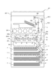
図2は、本発明の実施の形態に係るシート搬送装置を備えた画像形成装置の一例であるフルカラーレーザビームプリンタの概略構成を示す図である。図2において、201はフルカラーレーザビーム複写機、201Aは画像形成装置本体であるプリンタ本体、201Bはシートに画像を形成する画像形成部、220は定着部である。202はプリンタ本体201Aの上方に略水平に設置された上部装置である画像読取装置であり、この画像読取装置202とプリンタ本体201Aとの間に、シート排出用の排出空間が形成されている。プリンタ本体下部には、シート給送部を構成するシート搬送装置1が配置されている。
[Example 1]
(Image forming device)
FIG. 2 is a diagram showing a schematic configuration of a full-color laser beam printer which is an example of an image forming apparatus provided with a sheet conveying apparatus according to an embodiment of the present invention. In FIG. 2, 201 is a full-color laser beam copying machine, 201A is a printer main body that is an image forming apparatus main body, 201B is an image forming unit that forms an image on a sheet, and 220 is a fixing unit.
画像形成部201Bは、4ドラムフルカラー方式のものであり、レーザスキャナ210と、イエロー(Y)、マゼンタ(M)、シアン(C)及びブラック(K)の4色のトナー画像を形成する4個のプロセスカートリッジ211を備えている。ここで、各プロセスカートリッジ211は、感光体ドラム212、帯電手段である帯電器213、現像手段である現像器214及び不図示のクリーニング手段であるクリーナを備えている。また、画像形成部201Bは、プロセスカートリッジ211の上方に配された中間転写ユニット201Cを備えている。
The
中間転写ユニット201Cは、駆動ローラ216a及びテンションローラ216bに巻き掛けられた中間転写ベルト216を備えている。中間転写ベルト216は、各感光体ドラム212に接するように配置され、不図示の駆動部により駆動される駆動ローラ216aにより矢印方向に回転する。また、中間転写ユニット201Cは、中間転写ベルト216の内側に設けられ、感光体ドラム212に対向した位置で中間転写ベルト216に当接する1次転写ローラ219を備えている。中間転写ユニット201Cの駆動ローラ216aと対向する位置には、中間転写ベルト216上に形成されたカラー画像をシートに転写する2次転写部を構成する2次転写ローラ16が設けられている。中間転写ユニット201Cの上方には、各色のトナーを収容したトナーカートリッジ215が設けられている。
The
中間転写ベルト216に1次転写ローラ219によって正極性の転写バイアスを印加することにより、感光体ドラム212上の負極性を持つ各色トナー像が順次中間転写ベルト216に多重転写される。
By applying a positive transfer bias to the
シート給送部により給送されたシートは、レジストレーションローラ対15に搬送され、このレジストレーションローラ対15によって斜行が補正される。そして、シートは、レジストレーションローラ対15により、中間転写ベルト216に形成されたカラー画像とシートの先端とが一致するタイミングで2次転写部に搬送され、中間転写ベルト216上のトナー像が転写される。
The sheet fed by the sheet feeding unit is conveyed to the
トナー像が転写されたシートは、定着部220において熱及び圧力を受けてシートにカラーの画像として定着される。画像が定着されたシートPは、排紙ローラ対225によって排出空間に排出されて積載される。なお、シートの両面に画像を形成する際は、画像が定着された後、シートPは両面反転部201Dに設けられた正逆転可能な反転ローラ対222により、再搬送通路Rに搬送され、この後、再度、画像形成部201Bに搬送される。
The sheet on which the toner image has been transferred receives heat and pressure at the
(シート搬送装置)
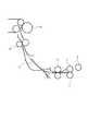
図3は、本実施例のシート搬送装置1を示す部分斜視図である。シート搬送装置1を構成するシート給送部に配設されたピックアップローラ2、フィードローラ3、リタードローラ4は、共通の駆動源である給紙モータM1により駆動される。フィードローラ3は、フィードローラ軸3a上に、軸と一体回転可能に保持される。ピックアップローラ2は、フィードローラ軸3a中心に回動可能なピックアップアーム2aの支軸2b上に、回転自在に保持される。リタードローラ4は、リタードローラ軸4a上に、トルクリミッタ5を介して回転自在に保持される。給紙モータM1を駆動すると、ギア6a、6bを介してフィードローラ軸3aに駆動が伝達され、フィードローラ3が回転する。フィードローラ軸3aの回転は、ギア6c、6d、6eを介してピックアップローラ2に、ギア6b、6f、6gを介してリタードローラ軸4aに伝達される。なお、フィードローラ3およびギア6cと、フィードローラ軸3aとの間には各々ワンウェイクラッチが介在している。これにより、給紙モータM1の駆動が切れた状態であっても、フィードローラ3およびピックアップローラ2は、下流のローラにより搬送されるシートPに連れ回り、搬送抵抗になることはない。
(Sheet conveying device)
FIG. 3 is a partial perspective view showing the
シートPを給送する際は、給紙トレイ7に積載されたシートPの最上面に対して、ピックアップローラ2を所定の付勢力で当接した状態で、給紙モータM1を駆動する。ピックアップローラ2の当接回転により繰り出されたシートPは、フィードローラ3とリタードローラ4との圧接により形成される分離ニップまで給送される。
When feeding the sheet P, the sheet feeding motor M1 is driven with the
分離ニップにシートPが無い状態、もしくは、分離ニップで1枚のシートPを搬送している状態では、トルクリミッタ5の滑りが生じて、リタードローラ4は、リタードローラ軸4aの回転方向とは逆のシートPの給送方向に連れ回る。一方、分離ニップに複数枚の重なったシートPが進入した状態では、リタードローラ4は、リタードローラ軸4aの駆動方向に回転する。すなわち、重送したシートP間の滑りにより、フィードローラ3に接するシートPは給送方向に搬送され、リタードローラ4に接するシートPは給紙トレイ7へ戻す方向に搬送される。
When there is no sheet P in the separation nip or when a single sheet P is conveyed in the separation nip, the torque limiter 5 slips, and the
このように、分離ニップに搬送されたシートPは、フィードローラ3とリタードローラ4によって1枚ずつ分離されて、下流の引抜ローラ対8(図2参照)に給送される。
In this way, the sheets P conveyed to the separation nip are separated one by one by the feed roller 3 and the
シート搬送装置1は、シートを搬送する第1の搬送ローラ対としての引抜ローラ対8と、前記引抜ローラ対8よりもシートの搬送方向下流側に設けられた第2の搬送ローラ対としてのレジローラ対15と、を有している。引抜ローラ対8は、給紙モータM1とは異なる第1の駆動手段としての引抜モータM2(図4参照)により駆動される。レジストレーションローラ対15は引抜モータM2とは異なる第2の駆動手段としてのレジストレーションモータM3(図4参照)により駆動される。以下、レジストレーションローラ対をレジローラ対、レジストレーションモータをレジモータという。
The
引抜ローラ対8にて搬送されるシートPは、引抜ローラ対8下流のレジストレーションセンサ12(図2参照)でシート先端を検知された後、回転停止中のレジローラ対15(図2参照)に突き当てられレジループ形成する。以下、レジストレーションセンサをレジセンサという。所定時間停止した後、シートPはレジローラ対15によって、シートに画像を転写する2次転写部(転写部)を構成する2次転写ローラ16に搬送され画像形成プロセスに向かう。
The sheet P conveyed by the drawing
レジローラ対15のニップ部におけるレジループ形成は、搬送中に斜行したシートPの斜行状態を是正し(斜行取り)、画像形成部である2次転写ローラに傾きや横ずれの無い状態にして搬送するために行われる。
The registration loop formation at the nip portion of the
(制御ブロック図)
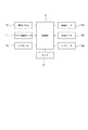
図4は、本実施例の画像形成装置201における制御系のブロック図である。制御部9には、ユーザがシートPの材質や坪量を選択入力する操作パネル10、給紙トレイ7に積載されたシートPのサイズを検出するサイズ検知センサ11、引抜ローラ対8とレジローラ対15の間の搬送パス上に配設されるレジセンサ12が接続される。また、制御部9には、計時手段であるタイマ13が接続される。接続された入力情報に基づき、制御部9は、給紙モータM1、引抜モータM2、およびレジモータM3の動作を制御する。
(Control block diagram)
FIG. 4 is a block diagram of a control system in the
(シート長さ)
なお、サイズ検知センサ11は、給紙トレイ7に積載されたシートPのサイズのうち、シートPの搬送方向の長さであるシート長さLを検出するものである。
(Sheet length)
The
(給送速度)
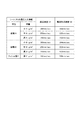
図5は、本実施例の画像形成装置におけるシートの給送速度V1および画像形成速度V2を示す表である。本実施例の画像形成装置201は、操作パネル10により選択入力されるシートPの材質や坪量に応じて、複数の画像形成速度V2を有する。これは、熱容量の高い材質もしくは坪量のシートPは、定着により多くの熱量を必要とするためである。すなわち、画像形成速度V2を遅くして、シートPに与える単位時間当たりの熱量を多くしている。本実施例の画像形成装置201は、画像形成速度V2に対応して、給送速度V1も複数有している。シートPに与える単位時間当たりの熱量を多くすることは、シートPの用紙種の特徴として、用紙坪量が大きく、用紙剛度が高いことにおおよそ比例している。
(Feeding speed)
FIG. 5 is a table showing the sheet feeding speed V1 and the image forming speed V2 in the image forming apparatus of the present embodiment. The
本実施例では、制御部9が、シートの種類に応じて、複数の給送速度V1のうちのいずれかを選択する。ここでは、シートの種類としてのシートの剛度に応じて給送速度V1が選択される構成を例示している。図5では、シートの坪量と紙種とを用いて、シートのコシ(剛性)に相当するシートの剛度を表し、このシートの剛度に応じて、シートの給送速度V1、画像形成速度V2が選択される。
In this embodiment, the
また図5では、シートの坪量として3種の坪量を例示している。シートの坪量「小」は100g/m2までの範囲であり、坪量「中」は101〜130g/m2の範囲であり、坪量「高」は131g/m2以上の範囲としている。ここでは、シートの坪量として、範囲の異なる3種の坪量を例示しているが、この3種に限定されるものではなく、必要に応じて適宜設定すれば良い。また、3種のシート坪量の範囲についても、前述の範囲に限定されるものではなく、必要に応じて適宜設定すれば良い。なお、図7を用いて後述するが、シートの坪量として「高」が選択入力された場合は、制御部は第1の搬送速度である給送速度V1(ここでは150mm/sec)を選択して第1の制御モードを実行する。一方、シートの坪量として「大」以外(ここでは「小」又は「中」)の坪量が選択された場合は、制御部は第1の搬送速度より速い第2の搬送速度である給送速度V1(ここでは250mm/sec又は300mm/sec)を選択して第2の制御モードを実行する。なお、画像形成速度V2は、給送速度V1が選択されることで、それに対応する画像形成速度が選択される。 FIG. 5 illustrates three types of basis weights as the basis weight of the sheet. The basis weight “small” of the sheet is in the range up to 100 g / m 2 , the basis weight “medium” is in the range of 101 to 130 g / m 2 , and the basis weight “high” is in the range of 131 g / m 2 or more. . Here, as the basis weight of the sheet, three types of basis weights having different ranges are illustrated, but the sheet basis weight is not limited to these three types, and may be appropriately set as necessary. Also, the ranges of the three types of sheet basis weights are not limited to the above-described ranges, and may be set as appropriate. As will be described later with reference to FIG. 7, when “high” is selected and input as the basis weight of the sheet, the control unit selects the feeding speed V <b> 1 (here, 150 mm / sec) that is the first conveyance speed. Then, the first control mode is executed. On the other hand, when a basis weight other than “large” (in this case, “small” or “medium”) is selected as the basis weight of the sheet, the control unit feeds at a second conveyance speed that is faster than the first conveyance speed. The second control mode is executed by selecting the feed speed V1 (here, 250 mm / sec or 300 mm / sec). Note that the image forming speed V2 is selected by selecting the feeding speed V1.
また図5では、紙種として、上質紙などを含む普通紙を紙種A、再生紙を紙種B、OHPシートなどの樹脂シートをフィルム類Fとして例示している。紙種Bの方が紙種Aよりもシートのコシ(剛度)が強い。ここで例示している紙種Bとしての再生紙は、紙種Aとしての普通紙よりもコシが強いが、給送速度を変更する必要がある程ではないため、図5に示す通り、紙種A,Bの各坪量に対応する給送速度V1,画像形成速度V2が同じ速度に設定されている。また、フィルム類Fとしての樹脂シートの方が前述の紙種A,Bよりもコシが強い。また、ここでは樹脂シートとしてOHPシートを例示しているため、坪量「高」の1種のみを例示している。これらの紙種は、前述のシートの坪量とともに操作パネルから選択入力され、これらのシートの種類の情報に基づくシートの剛度に応じて、制御部が給送速度V1、画像形成速度V2を選択する。具体的には図7を用いて後述するが、制御部9は、第1の剛度を有するシートを搬送する場合に、後述する第1の制御モードを選択し、前記第1の剛度よりも低い第2の剛度を有するシートを搬送する場合に、後述する第2の制御モードを選択する。
In FIG. 5, as paper types, plain paper including high-quality paper and the like are illustrated as paper type A, recycled paper as paper type B, and resin sheets such as OHP sheets as films F. The paper type B is stronger in stiffness (stiffness) than the paper type A. The recycled paper as the paper type B illustrated here is stronger than the plain paper as the paper type A, but it is not necessary to change the feeding speed. Therefore, as shown in FIG. The feeding speed V1 and the image forming speed V2 corresponding to each basis weight of the seeds A and B are set to the same speed. Further, the resin sheet as the film F is stronger than the paper types A and B described above. Moreover, since the OHP sheet is illustrated here as the resin sheet, only one type of basis weight “high” is illustrated. These paper types are selected and input from the operation panel together with the basis weight of the sheet, and the control unit selects the feeding speed V1 and the image forming speed V2 according to the sheet stiffness based on the information on the sheet type. To do. Specifically, as will be described later with reference to FIG. 7, when the
本実施例に係るシート搬送装置を備えた画像形成装置は、制御手段としての制御部9(図4参照)によって、以下に説明する、第1の制御モード又は第2の制御モードを選択的に切り換えて実行する。 In the image forming apparatus including the sheet conveying apparatus according to the present embodiment, a control unit 9 (see FIG. 4) as a control unit selectively selects a first control mode or a second control mode, which will be described below. Switch and execute.
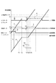
(第1の制御モード)
図8は、本実施例の第1の制御モードが適用される、給送速度V1が第1の搬送速度(ここでは150mm/sec)の場合の搬送線図および駆動線図である。
(First control mode)
FIG. 8 is a conveyance diagram and a drive diagram when the first control mode of the present embodiment is applied and the feeding speed V1 is the first conveyance speed (150 mm / sec in this case).
図8において、AはシートPの先端位置の理論線、BはシートPの後端位置の理論線である。Dは給紙モータM1により駆動されるピックアップローラ2およびフィードローラ3の駆動周速、Eは引抜モータM2により駆動される引抜ローラ対8の駆動周速、FはレジモータM3により駆動されるレジローラ対15の駆動周速を示す。V1は給送速度、V2は画像形成速度である。シートPの後端位置の理論線Bは、シートPの先端位置の理論線Aおよびサイズ検知センサ11により検出されたシートPの長さLから演算により求めることができる。
In FIG. 8, A is a theoretical line at the leading end position of the sheet P, and B is a theoretical line at the trailing end position of the sheet P. D is a driving peripheral speed of the
第1の制御モードにおいては、引抜ローラ対8は、引抜モータM2によって第1の給送速度(給送速度V1、図5中の150mm/sec)にて回転駆動される。この引抜ローラ対8によって搬送されたシートPがレジセンサ12で先端位置を検知され(制御時間T1)、停止したレジローラ対15に対して演算された距離分を搬送される。これにより、シートは、設定されたレジループをレジローラ対15のニップ部にて形成される。ループ形成後、引抜ローラ対8は停止される(制御時間T2)。設定された時間停止した後、レジローラ対15がレジモータM3にて画像形成速度V2でシートPの搬送を開始する(制御時間T3)。引抜ローラ対8も引抜モータM2によって前記レジローラ対15のシート搬送速度と同一となるシート搬送速度である画像形成速度V2(図5中の132mm/sec)にてシートPの搬送を開始(回転を開始)する(レジON動作)。
In the first control mode, the drawing
この引抜ローラ対8の速度V2での搬送開始タイミングは、制御時間T3と同時、または、引抜ローラ対が同期しない場合にレジループが解消される距離分の制御時間X1を考慮した制御時間T4に到達する前までの範囲内に開始する。すなわち、引抜ローラ対8は、ループ形成後、レジローラ対15の回転開始と同時、または前記ループが解消される前に、シートPの搬送を開始する。この引抜ローラ対8及びレジローラ対15の速度V2での駆動は、シートPの後端Bが各ローラ対を通過するに足りる時間後に駆動OFFされる。第1の制御モードでは、シートのループを解消せずにシートを搬送する。したがって、レジローラ対15がバックテンションを受けずにシートを搬送できるので、剛度が高いことで搬送抵抗が大きいシートであっても安定して搬送できる。
The conveyance start timing at the speed V2 of the
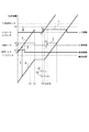
(第2の制御モード)
図9は、本実施例の第2の制御モードが適用される、給送速度V1が前記第1の搬送速度より速い第2の搬送速度(ここでは300mm/secまたは250mm/sec)の場合の搬送線図および駆動線図である。
(Second control mode)
FIG. 9 shows a case where the second control mode of the present embodiment is applied and the feed speed V1 is a second transport speed (300 mm / sec or 250 mm / sec in this case) faster than the first transport speed. It is a conveyance diagram and a drive diagram.
図9において図8同様に、AはシートPの先端位置の理論線、BはシートPの後端位置の理論線である。Dは給紙モータM1により駆動されるピックアップローラ2およびフィードローラ3の駆動周速、Eは引抜モータM2により駆動される引抜ローラ対8の駆動周速、FはレジモータM3により駆動されるレジローラ対15の駆動周速を示す。V1は給送速度、V2は画像形成速度である。シートPの後端位置の理論線Bは、シートPの先端位置の理論線Aおよびサイズ検知センサ11により検出されたシートPの長さLから演算により求めることができる。
In FIG. 9, as in FIG. 8, A is a theoretical line at the leading end position of the sheet P, and B is a theoretical line at the trailing end position of the sheet P. D is a driving peripheral speed of the
第2の制御モードにおいては、引抜ローラ対8は、引抜モータM2によって前記第1の搬送速度より速い第2の給送速度(給送速度V1、図5中の300mm/secまたは250mm/sec)にて回転駆動される。引抜ローラ対8によって搬送されたシートPがレジセンサ12で先端位置を検知され(制御時間T1)、停止したレジローラ対15に対して演算された距離分を搬送される。これにより、シートは、設定されたレジループをレジローラ対15のニップ部にて形成される。ループ形成後、引抜ローラ対8は停止される(制御時間T2)。設定された時間停止した後、レジローラ対15がレジモータM3にて画像形成速度V2でシートPの搬送を開始する(制御時間T3)。引抜ローラ対8は、制御時間T3よりも制御時間X2遅れた制御時間T5において、引抜モータM2によって前記レジローラ対15のシート搬送速度と同一となるシート搬送速度である画像形成速度V2(図5中の222mm/secまたは264mm/sec)にてシートPの搬送を開始する(レジON動作)。
In the second control mode, the drawing
この引抜ローラ対8の速度V2での搬送開始タイミングの制御時間T5は、引抜ローラ対が同期しない場合にレジループ解消される距離分の制御時間X1を考慮した制御時間T4より後で、位置制御時間T6より前で、かつ、シートPの先端Aが2次転写ローラ16に接触しない安全な位置Y1に到達するまでの制御時間X2の範囲内に設定される。すなわち、引抜ローラ対8は、ループ形成後にレジローラ対15が回転開始されて前記ループが解消された後、シートPの先端Aが2次転写ローラに到達する前までに、シートPの搬送を開始する。この引抜ローラ対8及びレジローラ対15の速度V2での駆動は、シートPの後端Bが各ローラ対を通過するに足りる時間後に駆動OFFされる。
The control time T5 of the conveyance start timing at the speed V2 of the
(比較例の制御モード構成)
本実施例の構成を説明するうえで、比較例としての従来構成を説明する。図12は比較例に係る搬送用紙と搬送ローラ配置略図である。なお、比較例(従来)の制御モードは、給送速度V1の選択状態にかかわらず、前述した第1の制御モードが適用される。
(Control mode configuration of comparative example)
In describing the configuration of the present embodiment, a conventional configuration as a comparative example will be described. FIG. 12 is a schematic diagram of the arrangement of conveyance paper and conveyance rollers according to a comparative example. Note that, as the control mode of the comparative example (conventional), the above-described first control mode is applied regardless of the selection state of the feeding speed V1.
引抜ローラ対8は、レジローラ対15よりもシートの搬送方向上流側の搬送ローラ対の中で最もニップ圧(ニップ部の加圧力)が高いが、図12に示すようにニップ部のスラスト方向範囲(シートの搬送方向と直交する幅方向のローラ幅)は最小ではない構成である。
The drawing
斜行してレジループを形成した場合において、制御時間T3でレジON動作後、シート先端側は斜行補正されるが、シート後端側は斜行した姿勢のままである。そのため、レジローラ対15とその上流のローラ対である引抜ローラ対8との間に形成されたループにねじれが生じる。この状態でシートの搬送が継続されると、シートにかかるせん断力が徐々に増大し、増大したせん断力がシートの剛性を上回るとシートが座屈することがある。すると、下流のレジローラ対15のニップ部を通過する際に、シートにシワが発生するおそれがある。シワは、ループを形成する2対のローラで挟持搬送する距離が長いシートや、座屈し易い剛度が低いシートである程、発生し易い傾向にある。さらに、2対のローラ間距離が短く構成される場合、顕著に発生し易い傾向にある。
When the registration loop is formed by skewing, after the registration ON operation at the control time T3, the sheet leading side is corrected to skew, but the sheet trailing end side remains skewed. For this reason, a twist is generated in the loop formed between the
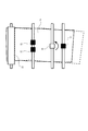
(実施例の制御モード構成)
図6は本実施例に係る画像形成装置の概略断面図、図1は本実施例に係る搬送用紙と搬送ローラ配置略図である。
(Control mode configuration of the embodiment)
FIG. 6 is a schematic cross-sectional view of the image forming apparatus according to the present embodiment, and FIG.
なお、本実施例では、シートの剛度(材質と坪量)に応じて給送速度V1が設定される。そして、シートの剛度に応じて設定された給送速度V1が第1の搬送速度(ここでは図5に示す150mm/sec)の場合、前述した第1の制御モードが適用される。一方、シートの剛度に応じて設定された給送速度V1が第1の搬送速度より速い第2の搬送速度(ここでは図5に示す300mm/secまたは250mm/sec)の場合、前述した第2の制御モードが適用される。 In this embodiment, the feeding speed V1 is set according to the rigidity (material and basis weight) of the sheet. When the feeding speed V1 set according to the stiffness of the sheet is the first transport speed (here, 150 mm / sec shown in FIG. 5), the first control mode described above is applied. On the other hand, when the feeding speed V1 set according to the stiffness of the sheet is a second transport speed (here, 300 mm / sec or 250 mm / sec shown in FIG. 5) higher than the first transport speed, the second speed described above. The control mode is applied.
引抜ローラ対8はレジローラ対15よりもシートの搬送方向上流側の搬送ローラ対の中で最もニップ圧(ニップ部の加圧力)が高く、図1に示すようにニップ部のスラスト方向範囲(シートの搬送方向と直交する幅方向のローラ幅)は最小である構成である。
The drawing
斜行してレジループを形成した場合において、制御時間T3でレジON動作後、シート先端側は斜行補正されるが、シート後端側は斜行した姿勢のままである。そのため、レジローラ対15とその上流のローラ対である引抜ローラ対8との間に形成されたループにねじれが生じる。この状態でシートの搬送が継続されると、シートにかかるせん断力が徐々に増大される。
When the registration loop is formed by skewing, after the registration ON operation at the control time T3, the sheet leading side is corrected to skew, but the sheet trailing end side remains skewed. For this reason, a twist is generated in the loop formed between the
そのため、上流の搬送ローラ対である引抜ローラ対8は、レジローラ対15の搬送開始タイミングである制御時間T3より制御時間X2遅れた搬送開始タイミングの制御時間T5で駆動を開始する。制御時間X2の間、シートPはレジローラ対15に搬送されながら、停止した引抜ローラ対8に引っ張られる。さらに、レジローラ対15の上流の搬送ローラ対の中で引抜ローラ対8はニップ圧が高く、ローラ幅の狭いローラ対であるため、シートPは引抜ローラ対8を支点にレジローラ対15の引っ張り力によってねじれを解消しながら旋回する。この旋回により、シートのねじれの解消とともにせん断力が増大することなく解消される。そのため、シートにかかるせん断力がシートの剛性を上回ってシートが座屈することを防ぎ、下流のレジローラ対15のニップ部を通過する際に、シートのシワの発生を抑制できる。
For this reason, the drawing
よって、ループを形成する2対のローラ8,15間の距離が短く構成される画像形成装置であっても、搬送距離が長く、剛度の低いシートに対して、せん断力が増大する前にループを解消し、シートのシワの発生を防止することができる。
Accordingly, even in an image forming apparatus in which the distance between the two pairs of
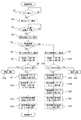
(制御フローチャート)
本実施例の画像形成装置201における給送制御を、図7に示すフローチャートを用いて説明する。なお、以下に説明する給送制御は、図4に示す制御手段としての制御部9によって行われる。
(Control flowchart)
The feeding control in the
給紙トレイ7にシートPを積載すると、制御部9は、サイズ検知センサ11によりサイズを検出し(S1)、シート長さLを確定する(S2)。ユーザが、操作パネル10上でシートPの材質と坪量を選択入力すると(S3)、制御部9は入力されたシートの種類に関する情報に応じて、図5に従い給送速度V1を確定する(S4)。選択入力されたシートPの材質と坪量から確定した給送速度V1が第1の搬送速度(ここでは150mm/sec)の場合は(S5)、第1の制御モードが適用される(S6)。一方、シートPの材質と坪量から確定した給送速度V1が第1の搬送速度より速い第2の搬送速度の場合は、第2の制御モードが適用される(S7)。
When the sheets P are stacked on the
制御部9は、第1の制御モードにおいて、給紙モータM1および引抜モータM2を給送速度V1(第1の搬送速度)にて駆動開始すると(S8)、レジセンサ12によるシートPの先端検出を行う(S9)。シートPの先端が、所定時間内にレジセンサ12に到達しない場合は、遅延JAMと判断する(S10)。一方、レジセンサ12が所定時間内にシートPの先端を検出すると、停止したレジローラ対15に対してシートPを搬送してループを形成する制御時間T2のタイミングにて、引抜モータM2をOFFする(S11)。シートPのループ形成後、制御時間T3のタイミングにて、前記確定した給送速度V1に対応する画像形成速度V2にてレジモータM3、引抜モータM2をONする(S12)。これにより、レジローラ対15が確定した給送速度V1に応じた画像形成速度V2にて回転駆動されるとともに、引抜ローラ対8が前記レジローラ対15のシート搬送速度と同一となるシート搬送速度(画像形成速度V2)にて回転駆動される。その後、シートPの後端が引抜ローラ対8を抜ける所定時間で引抜モータM2をOFFし(S13)、シートPの後端がレジローラ対15を抜ける所定時間でレジモータM3をOFFし(S14)、給送動作を完了する。
In the first control mode, the
一方、制御部9は、第2の制御モードにおいて、給紙モータM1および引抜モータM2を給送速度V1(第2の搬送速度)にて駆動開始すると(S15)、同様に、レジセンサ12によるシートPの先端検出を行う(S16)。シートPの先端が、所定時間内にレジセンサ12に到達しない場合は、遅延JAMと判断する(S17)。一方、レジセンサ12が所定時間内にシートPの先端を検出すると、停止したレジローラ対15に対してシートPを搬送してループを形成する制御時間T2のタイミングにて、引抜モータM2をOFFする(S18)。シートPのループ形成後、制御時間T3のタイミングにて、前記確定した給送速度V1(第2の搬送速度)に対応する画像形成速度V2にてレジモータM3をONする(S19)。このとき、引抜モータM2はOFFのままである。その後、制御時間T3より制御時間X2遅れた制御時間T5のタイミングにて、前記レジローラ対15のシート搬送速度と同一となるシート搬送速度(画像形成速度V2)にて引抜モータM2をONする(S20)。これにより、レジローラ対15が確定した給送速度V1に応じた画像形成速度V2にて回転駆動されて、シートPのループが解消される。さらにシートPのループが解消された後に、引抜ローラ対8が前記レジローラ対15のシート搬送速度(画像形成速度V2)と同一となるシート搬送速度(画像形成速度V2)にて回転駆動される。その後、シートPの後端が引抜ローラ対8を抜ける所定時間で引抜モータM2をOFFし(S21)、シートPの後端がレジローラ対15を抜ける所定時間でレジモータM3をOFFし(S22)、給送動作を完了する。
On the other hand, in the second control mode, the
本実施例によれば、ループを形成する2対のローラ8,15間の距離が短く構成される画像形成装置であっても、搬送距離が長く、剛度の低いシートに対して、せん断力が増大する前にループを解消し、シートのシワの発生を防止することができる。なお、レジループは完全に解消されずに低減させるようにしてもよく、この場合もシワの発生を防ぐことができる。
According to the present embodiment, even in an image forming apparatus in which the distance between the two pairs of
〔実施例2〕
(実施例の制御モード構成)
図10は本実施例に係る画像形成装置の概略断面図、図11は本実施例に係る搬送用紙と搬送ローラ配置略図である。
[Example 2]
(Control mode configuration of the embodiment)
FIG. 10 is a schematic cross-sectional view of the image forming apparatus according to this embodiment, and FIG. 11 is a schematic view of the arrangement of the conveyance paper and conveyance rollers according to this embodiment.
なお、本実施例では、前述した実施例1と同様に、シートの剛度(材質と坪量)に応じて給送速度V1が設定される。すなわち、シートの剛度に応じて設定された給送速度V1が第1の搬送速度(ここでは図5に示す150mm/sec)の場合、前述した第1の制御モードが適用される。一方、シートの剛度に応じて設定された給送速度V1が第1の搬送速度より速い第2の搬送速度(ここでは図5に示す300mm/secまたは250mm/sec)の場合、前述した第2の制御モードが適用される。 In the present embodiment, similarly to the first embodiment described above, the feeding speed V1 is set according to the stiffness (material and basis weight) of the sheet. That is, when the feeding speed V1 set according to the stiffness of the sheet is the first transport speed (here, 150 mm / sec shown in FIG. 5), the first control mode described above is applied. On the other hand, when the feeding speed V1 set according to the stiffness of the sheet is a second transport speed (here, 300 mm / sec or 250 mm / sec shown in FIG. 5) higher than the first transport speed, the second speed described above. The control mode is applied.
本実施例では、第1の搬送ローラ対である引抜ローラ対8よりもシートの搬送方向下流側であって、第2の搬送ローラ対であるレジローラ対15よりもシートの搬送方向上流側に、シートを搬送する第3の搬送ローラ対であるレジ前ローラ対17が配置されている。すなわち、前述した実施例1におけるレジローラ対15と引抜ローラ対8の間にレジ前ローラ対17が配置された構成となっている。レジ前ローラ対17は、制御部9によって制御される、レジモータM3や引抜モータM2とは別のモータによって駆動される。引抜ローラ対8はレジローラ対15より上流の搬送ローラ対の中で最もニップ圧(ニップ部の加圧力)が高く、図11に示すようにニップ部のスラスト方向範囲(シートの搬送方向と直交する幅方向のローラ幅)は最小である構成である。すなわち、引抜ローラ対8は、そのニップ圧がレジローラ対15より低いがレジ前ローラ対17よりも高い。引抜ローラ対8は、シート幅方向の長さがレジローラ対15やレジ前ローラ対17よりも狭い構成である。
In this embodiment, the sheet conveyance direction downstream side of the
斜行してレジループ形成した場合において、制御時間T3でレジON動作後、シート先端側は斜行補正されるが、シート後端側は斜行した姿勢のままである。そのため、レジローラ対15とその上流の引抜ローラ対8との間に形成されたループにねじれが生じる。この状態でシート搬送が継続されると、シートにかかるせん断力が徐々に増大される。
In the case where the registration loop is formed by skewing, after the registration ON operation at the control time T3, skew correction is performed on the sheet leading end side, but the sheet trailing end side remains skewed. Therefore, a twist is generated in a loop formed between the
そのため、本実施例においても、前述した実施例と同じ条件で第1の制御モード、または第2の制御モードが選択的に実施される。すなわち、引抜ローラ対8は制御時間T3、または制御時間T3より制御時間X2遅れた搬送開始タイミングの制御時間T5で駆動を開始する。特に制御時間X2の間、シートPはレジローラ対15に搬送されながら、停止した引抜ローラ対8に引っ張られる。本実施例では、レジローラ対15と引抜ローラ対8の間にレジ前ローラ対17があるが、レジ前ローラ対17は引抜ローラ対8よりもニップ圧が低い。そのため、制御時間T5のタイミングで引抜ローラ対8の駆動をONすると、シートPの引っ張りの作用はレジローラ対15と引抜ローラ対8間で発生する。これにより、レジローラ対15よりシートの搬送方向上流の搬送ローラ対の中で引抜ローラ対8は最もニップ圧が高く、幅の狭いローラ対であることで、シートPは引抜ローラ対8を支点に引っ張り力によってねじれを解消しながら旋回する。この旋回により、同様にねじれの解消とともにせん断力が増大することなく解消される。そのため、シートにかかるせん断力がシートの剛性を上回ってシートが座屈することを防ぎ、下流のレジローラ対15のニップ部を通過する際に、シートのシワの発生を抑制できる。なお、本実施形態では、シートにループを形成した後に、引抜ローラ対8と同じタイミングでレジ前ローラ対17の駆動をON(レジ前ローラ対17の回転を開始)させている。
Therefore, also in the present embodiment, the first control mode or the second control mode is selectively performed under the same conditions as in the above-described embodiments. That is, the drawing
よって、ループを形成する2対のローラ8,15間の距離が短く構成される画像形成装置であっても、搬送距離が長く、剛度の低いシートに対して、せん断力が増大する前にループを解消し、シートのシワの発生を防止することができる。
Accordingly, even in an image forming apparatus in which the distance between the two pairs of
なお、本実施例において、レジ前ローラ対17は、引抜ローラ対8と同様に、レジローラ対15との間で、シートにループを形成して斜行を補正するローラとしても機能する。シートPのうち、シートの搬送方向の長さLが、レジローラ対15と引抜ローラ対8の間の長さよりも短い場合がある。このようなシートPの場合、レジローラ対15と引抜ローラ対8とではシートの斜行を補正することができない。そこで、このレジ前ローラ対17は、シートの長さが、レジローラ対15と引抜ローラ対8の間の長さよりも短い場合に、シートのループを形成するローラとして機能する。
In the present embodiment, the
具体的には、例えば普通紙などに比べて、シートの搬送方向の長さLが短いハガキなどサイズのシートを搬送する場合である。このシートの搬送方向の長さLは、サイズ検知センサ11からの情報に基づいて制御部9によって算出される。シートPがハガキである場合、図7を用いて説明したように、まずサイズが検出され、シート長さLが確定される。その後、シートの材質と坪量が選択入力される。シートがハガキである場合、坪量として「高」が選択入力されるため、給送速度V1は第1の搬送速度(図5中の150mm/sec)が選択される。画像形成速度V2は、選択された給送速度V1に対応する画像形成速度が選択される。これにより、シートがハガキである場合は、第1の制御モードが選択される。
Specifically, for example, a sheet having a size such as a postcard whose length L in the sheet conveyance direction is shorter than that of plain paper or the like is conveyed. The length L in the sheet conveyance direction is calculated by the
そして、制御部9は、第1の制御モードにおいて、停止したレジローラ対15に対して、レジ前ローラ対17によりシートPを搬送してループを形成し、ループを形成した後、レジ前ローラ対17の駆動を停止する。シートPのループ形成後、所定のタイミング(図8の制御時間T3)にて、レジローラ対15は前記確定した給送速度V1に対応する画像形成速度V2にてシートPの搬送を開始する。レジ前ローラ対17も前記レジローラ対15のシート搬送速度と同一となるシート搬送速度である画像形成速度V2にてシートPの搬送を開始する(レジON動作)。その後、シートPの後端が引抜ローラ対8を抜ける所定時間でレジ前ローラ対17の駆動を停止し、シートPの後端がレジローラ対15を抜ける所定時間でレジローラ対15の駆動を停止し、給送動作を完了する。
Then, in the first control mode, the
このように本実施例では、レジローラ対15と引抜ローラ対8とでは対応できない長さのシートについてもループを形成して斜行を補正することができる。
As described above, in this embodiment, it is possible to correct a skew by forming a loop even for a sheet having a length that cannot be handled by the
なお、第2の制御モードにおいて、シートにループを形成した後、レジローラ対15と同じタイミングでレジ前ローラ対17の駆動をON(回転を開始)させ、ループを無くした後に引抜ローラ対8の回転を開始させるようにしてもよい。レジローラ対15をレジ前ローラ対17と同じタイミングで回転させても、引抜ローラ対8と比べてレジ前ローラ対17のニップ圧は低いので、レジローラ対15とレジ前ローラ対17との間のループを引抜ローラ対8の負荷によって低減させることができる。
In the second control mode, after forming a loop on the sheet, the
〔他の実施例〕
なお、前述した実施例1,2では、シートの種類として、シートの剛度(材質と坪量)を例示したが、給送速度を確定するためのシートの種類はこれに限定されるものではない。
[Other Examples]
In the first and second embodiments, the sheet stiffness (material and basis weight) is exemplified as the sheet type. However, the sheet type for determining the feeding speed is not limited to this. .
例えば、シートの種類として、シートの坪量のみを用いてもよい。この場合、制御部は、第1の坪量を有するシートを搬送する場合に、前記第1の制御モードを選択し、前記第1の坪量より小さい第2の坪量を有するシートを搬送する場合に、前記第2の制御モードを選択する。あるいは、シートの種類として、シートの厚さを用いてもよい。この場合、制御部は、第1の厚さを有するシートを搬送する場合に、前記第1の制御モードを選択し、前記第1の厚さよりも薄い第2の厚さを有するシートを搬送する場合に、前記第2の制御モードを選択する。このようにしても、前述した実施例と同様に、シートの種類に応じて制御モードを選択的に実施することで、シートのシワの発生を防止することができる。 For example, only the basis weight of the sheet may be used as the sheet type. In this case, when the sheet having the first basis weight is conveyed, the control unit selects the first control mode and conveys the sheet having the second basis weight smaller than the first basis weight. The second control mode is selected. Alternatively, the sheet thickness may be used as the sheet type. In this case, when the sheet having the first thickness is conveyed, the control unit selects the first control mode and conveys the sheet having the second thickness that is smaller than the first thickness. The second control mode is selected. Even in this case, as in the above-described embodiment, it is possible to prevent wrinkling of the sheet by selectively performing the control mode according to the type of the sheet.
また前述した実施例では、紙種Aと紙種Bはいずれも同じ坪量であれば、同じ給送速度が選択される構成を例示した。しかし、同じ坪量であっても、紙種Aの方が紙種Bよりもシートのコシ(剛性)が強い場合には、紙種Aが選択された場合には第1の制御モードを選択し、紙種Bが選択された場合には第2の制御モードを選択するようにしてもよい。こうすることで、前述した実施例と同様の効果が得られる。 Moreover, in the Example mentioned above, if the paper type A and the paper type B were both the same basis weight, the structure by which the same feeding speed was selected was illustrated. However, if the paper type A is stronger than the paper type B even if the paper weight is the same, the first control mode is selected when the paper type A is selected. However, when the paper type B is selected, the second control mode may be selected. By doing so, the same effect as the above-described embodiment can be obtained.
また前述した実施例では、3種のシート坪量に応じた給送速度V1を例示し、制御モードを選択するシートの給送速度V1を150mm/sec又はそれ以外とする構成を例示したが、本発明はこれに限定されるものではない。シートの種類に応じて確定した給送速度V1が、第1の給送速度である場合に前記第1の制御モードが選択され、 前記第1の搬送速度より速い第2の搬送速度である場合に前記第2の制御モードが選択されるようにしても良い。 In the above-described embodiment, the feeding speed V1 corresponding to the three kinds of sheet basis weights is exemplified, and the sheet feeding speed V1 for selecting the control mode is exemplified as 150 mm / sec or other configurations. The present invention is not limited to this. When the feeding speed V1 determined according to the sheet type is the first feeding speed, the first control mode is selected, and the feeding speed V1 is the second feeding speed that is faster than the first feeding speed. Alternatively, the second control mode may be selected.
また前述した実施例では、シート搬送装置を備えた画像形成装置としてプリンタを例示したが、本発明はこれに限定されるものではない。例えばスキャナ、複写機、ファクシミリ装置等の他の画像形成装置や、或いはこれらの機能を組み合わせた複合機等の他の画像形成装置であってもよい。これらの画像形成装置に用いられるシート搬送装置に本発明を適用することにより同様の効果を得ることができる。 In the above-described embodiments, the printer is exemplified as the image forming apparatus provided with the sheet conveying device. However, the present invention is not limited to this. For example, the image forming apparatus may be another image forming apparatus such as a scanner, a copier, or a facsimile machine, or another image forming apparatus such as a multifunction machine that combines these functions. Similar effects can be obtained by applying the present invention to a sheet conveying apparatus used in these image forming apparatuses.
また前述した実施例では、画像処理装置が一体的に有するシート搬送装置を例示したが、本発明はこれに限定されるものではない。例えば画像形成装置に対して着脱自在なシート搬送装置であっても良く、該シート搬送装置に本発明を適用することにより同様の効果を得ることができる。 Further, in the above-described embodiments, the sheet conveying apparatus integrally included in the image processing apparatus is illustrated, but the present invention is not limited to this. For example, the image forming apparatus may be a detachable sheet conveying apparatus, and the same effect can be obtained by applying the present invention to the sheet conveying apparatus.
また前述した実施例では、記録対象としての記録紙等のシートを画像形成部に搬送するシート搬送装置を例示したが、本発明はこれに限定されるものではない。例えば、読取対象としての原稿等のシートを画像読取部に搬送するシート搬送装置に適用しても同様の効果を得ることができる。 In the above-described embodiments, the sheet conveying apparatus that conveys a sheet such as a recording sheet as a recording target to the image forming unit is exemplified, but the present invention is not limited to this. For example, the same effect can be obtained even if the present invention is applied to a sheet conveying apparatus that conveys a sheet such as a document to be read to the image reading unit.
M1 …給紙モータ
M2 …引抜モータ
M3 …レジモータ
P …シート
1 …シート搬送装置
2 …ピックアップローラ
3 …フィードローラ
4 …リタードローラ
5 …トルクリミッタ
7 …給紙トレイ
8 …引抜ローラ対
9 …制御部
10 …操作パネル
11 …サイズ検知センサ
12 …レジセンサ
13 …タイマ
15 …レジローラ対
16 …2次転写ローラ
17 …レジ前ローラ対
201 …画像形成装置
201B …画像形成部
202 …画像読取装置
M1 ... paper feed motor M2 ... extraction motor M3 ... registration motor P ...
Claims (12)
前記シートにループを形成した後に前記第2の搬送ローラ対の回転を開始し、前記シートのループが解消される前に前記第1の搬送ローラ対の回転を開始する第1の制御モード、又は、前記シートのループを形成した後に前記第2の搬送ローラ対の回転を開始し、前記シートのループが解消された後に前記第1の搬送ローラ対の回転を開始する第2の制御モードを、選択的に実行する制御手段を有することを特徴とするシート搬送装置。 The leading edge of the sheet conveyed by the first conveying roller pair is abutted against the nip portion of the second conveying roller pair, which is provided on the downstream side of the first conveying roller pair in the sheet conveying direction and is stopped. A sheet conveying device that forms a loop in a sheet and corrects skew of the sheet,
A first control mode in which rotation of the second conveyance roller pair is started after forming a loop on the sheet, and rotation of the first conveyance roller pair is started before the loop of the sheet is eliminated; or A second control mode in which rotation of the second conveying roller pair is started after the loop of the sheet is formed, and rotation of the first conveying roller pair is started after the loop of the sheet is canceled, A sheet conveying apparatus having control means for selectively executing the sheet conveying apparatus.
前記シートにループを形成した後に前記シートのループが解消されないように前記第1の搬送ローラ対と前記第2の搬送ローラ対とでシートを搬送する第1の制御モード、又は、前記シートのループを形成した後に前記第2の搬送ローラ対の回転を開始してから前記第1の搬送ローラ対の回転を開始するまでの時間が前記第1の制御モードよりも長い第2の制御モードを、選択的に実行する制御手段を有することを特徴とするシート搬送装置。 The leading edge of the sheet conveyed by the first conveying roller pair is abutted against the nip portion of the second conveying roller pair, which is provided on the downstream side of the first conveying roller pair in the sheet conveying direction and is stopped. A sheet conveying device that forms a loop in a sheet and corrects skew of the sheet,
A first control mode in which a sheet is conveyed by the first conveying roller pair and the second conveying roller pair so that the loop of the sheet is not eliminated after the loop is formed on the sheet, or the loop of the sheet A second control mode in which the time from the start of rotation of the second transport roller pair to the start of rotation of the first transport roller pair is longer than the first control mode after forming A sheet conveying apparatus having control means for selectively executing the sheet conveying apparatus.
前記制御手段は、第1の剛度を有するシートを搬送する場合に、前記第1の制御モードを選択し、前記第1の剛度よりも低い第2の剛度を有するシートを搬送する場合に、前記第2の制御モードを選択することを特徴とする請求項3に記載のシート搬送装置。 The type of sheet is the stiffness of the sheet,
The control means selects the first control mode when transporting a sheet having a first stiffness, and transports a sheet having a second stiffness lower than the first stiffness. The sheet conveying apparatus according to claim 3, wherein the second control mode is selected.
前記制御手段は、第1の坪量を有するシートを搬送する場合に、前記第1の制御モードを選択し、前記第1の坪量より小さい第2の坪量を有するシートを搬送する場合に、前記第2の制御モードを選択することを特徴とする請求項3に記載のシート搬送装置。 The type of the sheet is the basis weight of the sheet,
The control means selects the first control mode when transporting a sheet having a first basis weight, and transports a sheet having a second basis weight smaller than the first basis weight. The sheet conveying apparatus according to claim 3, wherein the second control mode is selected.
前記制御手段は、第1の厚さを有するシートを搬送する場合に、前記第1の制御モードを選択し、前記第1の厚さよりも薄い第2の厚さを有するシートを搬送する場合に、前記第2の制御モードを選択することを特徴とする請求項3に記載のシート搬送装置。 The sheet type is the thickness of the sheet,
The control unit selects the first control mode when transporting a sheet having a first thickness, and transports a sheet having a second thickness that is smaller than the first thickness. The sheet conveying apparatus according to claim 3, wherein the second control mode is selected.
前記シート搬送装置により搬送されてきたシートに画像を形成する画像形成部と、
を備えることを特徴とする画像形成装置。 A sheet conveying device according to any one of claims 1 to 10,
An image forming unit that forms an image on the sheet conveyed by the sheet conveying device;
An image forming apparatus comprising:
前記第1の搬送ローラ対により搬送されるシートの先端が突き当てられる第2の搬送ローラ対と、
前記第2の搬送ローラ対によって搬送されるシートに画像を転写する転写部と、
シートの先端が前記第2の搬送ローラ対に突き当てられた後、前記第2の搬送ローラ対によって搬送されるシートの先端が前記転写部に到達する前であって前記第2の搬送ローラ対が回転を開始するタイミングよりも遅いタイミングで前記第1の搬送ローラ対の回転を開始させる制御手段と、を有することを特徴とする画像形成装置。 A first conveying roller pair;
A second conveying roller pair against which a leading edge of a sheet conveyed by the first conveying roller pair is abutted;
A transfer unit that transfers an image to a sheet conveyed by the second conveyance roller pair;
After the leading edge of the sheet is abutted against the second conveying roller pair, before the leading edge of the sheet conveyed by the second conveying roller pair reaches the transfer section, the second conveying roller pair An image forming apparatus comprising: control means for starting the rotation of the first conveying roller pair at a timing later than the timing at which the rotation starts.
Priority Applications (3)
| Application Number | Priority Date | Filing Date | Title |
|---|---|---|---|
| JP2016045162A JP2017159989A (en) | 2016-03-09 | 2016-03-09 | Sheet conveying device and image forming device |
| US15/447,688 US9994405B2 (en) | 2016-03-09 | 2017-03-02 | Sheet conveying apparatus and image forming apparatus |
| CN201710132924.0A CN107176480B (en) | 2016-03-09 | 2017-03-08 | Sheet conveying apparatus and image forming apparatus |
Applications Claiming Priority (1)
| Application Number | Priority Date | Filing Date | Title |
|---|---|---|---|
| JP2016045162A JP2017159989A (en) | 2016-03-09 | 2016-03-09 | Sheet conveying device and image forming device |
Publications (2)
| Publication Number | Publication Date |
|---|---|
| JP2017159989A true JP2017159989A (en) | 2017-09-14 |
| JP2017159989A5 JP2017159989A5 (en) | 2019-04-18 |
Family
ID=59786651
Family Applications (1)
| Application Number | Title | Priority Date | Filing Date |
|---|---|---|---|
| JP2016045162A Pending JP2017159989A (en) | 2016-03-09 | 2016-03-09 | Sheet conveying device and image forming device |
Country Status (3)
| Country | Link |
|---|---|
| US (1) | US9994405B2 (en) |
| JP (1) | JP2017159989A (en) |
| CN (1) | CN107176480B (en) |
Cited By (2)
| Publication number | Priority date | Publication date | Assignee | Title |
|---|---|---|---|---|
| JP2020083536A (en) * | 2018-11-21 | 2020-06-04 | キヤノン株式会社 | Sheet carrier and image forming apparatus |
| JP7375388B2 (en) | 2019-09-03 | 2023-11-08 | 富士フイルムビジネスイノベーション株式会社 | Conveyance device and image forming device |
Families Citing this family (3)
| Publication number | Priority date | Publication date | Assignee | Title |
|---|---|---|---|---|
| JP2019043701A (en) * | 2017-08-30 | 2019-03-22 | キヤノン株式会社 | Sheet conveying device and image forming device |
| JP2022017642A (en) * | 2020-07-14 | 2022-01-26 | キヤノン株式会社 | Image formation device |
| JP2022187115A (en) * | 2021-06-07 | 2022-12-19 | キヤノン株式会社 | image forming device |
Citations (8)
| Publication number | Priority date | Publication date | Assignee | Title |
|---|---|---|---|---|
| JPH10316276A (en) * | 1997-05-21 | 1998-12-02 | Ricoh Co Ltd | Paper carrying device |
| JP2002318518A (en) * | 2001-04-20 | 2002-10-31 | Canon Inc | Image forming device |
| US20030133732A1 (en) * | 2002-01-11 | 2003-07-17 | Xerox Corporation | Stall roll registration system and method employing a ball-on-belt input transport |
| JP2005247463A (en) * | 2004-03-02 | 2005-09-15 | Matsushita Electric Ind Co Ltd | Paper feed control method for image formation device |
| JP2005335935A (en) * | 2004-05-31 | 2005-12-08 | Fuji Xerox Co Ltd | Paper carrying device |
| JP2010030721A (en) * | 2008-07-28 | 2010-02-12 | Ricoh Co Ltd | Recording medium conveying device and image forming device |
| JP2013040019A (en) * | 2011-08-17 | 2013-02-28 | Konica Minolta Business Technologies Inc | Paper feeder, image reader and image forming apparatus |
| JP2015016947A (en) * | 2013-07-10 | 2015-01-29 | 株式会社リコー | Sheet conveying device and image forming device |
Family Cites Families (21)
| Publication number | Priority date | Publication date | Assignee | Title |
|---|---|---|---|---|
| US5982400A (en) * | 1991-08-22 | 1999-11-09 | Canon Kabushiki Kaisha | Sheet feeding apparatus and image forming system |
| JPH05116813A (en) | 1991-10-23 | 1993-05-14 | Ricoh Co Ltd | Transfer-paper feed method for image forming apparatus |
| JPH07157147A (en) | 1993-12-03 | 1995-06-20 | Ricoh Co Ltd | Paper conveyor |
| JPH10212054A (en) | 1997-01-29 | 1998-08-11 | Fuji Xerox Co Ltd | Document carrying device |
| JP2000118801A (en) | 1998-10-15 | 2000-04-25 | Canon Inc | Sheet conveyer device and image forming device furnished with sheet conveyer device |
| JP4109886B2 (en) | 2002-04-08 | 2008-07-02 | キヤノン株式会社 | Image forming apparatus |
| JP4227640B2 (en) | 2005-11-11 | 2009-02-18 | キヤノン株式会社 | Sheet processing apparatus and image forming apparatus provided with the same |
| JP4845658B2 (en) * | 2006-04-07 | 2011-12-28 | キヤノン株式会社 | Sheet conveying apparatus and image forming apparatus provided with the same |
| JP4242884B2 (en) * | 2006-09-01 | 2009-03-25 | シャープ株式会社 | Sheet conveying apparatus, and document conveying apparatus and image processing apparatus provided with the same |
| JP5201867B2 (en) | 2007-04-12 | 2013-06-05 | キヤノン株式会社 | Image forming apparatus |
| US7641188B2 (en) | 2007-04-24 | 2010-01-05 | Canon Kabushiki Kaisha | Sheet feeding apparatus and image forming apparatus |
| JP5178463B2 (en) | 2008-11-06 | 2013-04-10 | キヤノン株式会社 | Sheet feeding apparatus and image forming apparatus |
| JP5562066B2 (en) | 2010-02-26 | 2014-07-30 | キヤノン株式会社 | Image forming apparatus |
| US9042805B2 (en) * | 2010-09-02 | 2015-05-26 | Konica Minolta, Inc. | Image forming apparatus |
| JP5893642B2 (en) * | 2011-11-29 | 2016-03-23 | キヤノン株式会社 | Skew correction device and image forming apparatus |
| JP6029335B2 (en) | 2012-06-07 | 2016-11-24 | キヤノン株式会社 | Image forming apparatus |
| US8979088B2 (en) | 2012-11-02 | 2015-03-17 | Canon Kabushiki Kaisha | Sheet feeding apparatus and image forming apparatus |
| JP2015020902A (en) * | 2013-07-23 | 2015-02-02 | キヤノン株式会社 | Skew correction device and image forming apparatus |
| US9860403B2 (en) | 2015-06-10 | 2018-01-02 | Canon Kabushiki Kaisha | Sheet feeding apparatus, and reading apparatus and image forming apparatus using the same |
| JP6335854B2 (en) | 2015-09-02 | 2018-05-30 | キヤノン株式会社 | Sheet feeding apparatus and image forming apparatus |
| JP6180480B2 (en) * | 2015-09-03 | 2017-08-16 | キヤノン株式会社 | Sheet feeding apparatus and image forming apparatus |
-
2016
- 2016-03-09 JP JP2016045162A patent/JP2017159989A/en active Pending
-
2017
- 2017-03-02 US US15/447,688 patent/US9994405B2/en active Active
- 2017-03-08 CN CN201710132924.0A patent/CN107176480B/en active Active
Patent Citations (8)
| Publication number | Priority date | Publication date | Assignee | Title |
|---|---|---|---|---|
| JPH10316276A (en) * | 1997-05-21 | 1998-12-02 | Ricoh Co Ltd | Paper carrying device |
| JP2002318518A (en) * | 2001-04-20 | 2002-10-31 | Canon Inc | Image forming device |
| US20030133732A1 (en) * | 2002-01-11 | 2003-07-17 | Xerox Corporation | Stall roll registration system and method employing a ball-on-belt input transport |
| JP2005247463A (en) * | 2004-03-02 | 2005-09-15 | Matsushita Electric Ind Co Ltd | Paper feed control method for image formation device |
| JP2005335935A (en) * | 2004-05-31 | 2005-12-08 | Fuji Xerox Co Ltd | Paper carrying device |
| JP2010030721A (en) * | 2008-07-28 | 2010-02-12 | Ricoh Co Ltd | Recording medium conveying device and image forming device |
| JP2013040019A (en) * | 2011-08-17 | 2013-02-28 | Konica Minolta Business Technologies Inc | Paper feeder, image reader and image forming apparatus |
| JP2015016947A (en) * | 2013-07-10 | 2015-01-29 | 株式会社リコー | Sheet conveying device and image forming device |
Cited By (3)
| Publication number | Priority date | Publication date | Assignee | Title |
|---|---|---|---|---|
| JP2020083536A (en) * | 2018-11-21 | 2020-06-04 | キヤノン株式会社 | Sheet carrier and image forming apparatus |
| JP7267718B2 (en) | 2018-11-21 | 2023-05-02 | キヤノン株式会社 | Sheet conveying device and image forming device |
| JP7375388B2 (en) | 2019-09-03 | 2023-11-08 | 富士フイルムビジネスイノベーション株式会社 | Conveyance device and image forming device |
Also Published As
| Publication number | Publication date |
|---|---|
| CN107176480B (en) | 2020-01-31 |
| US9994405B2 (en) | 2018-06-12 |
| US20170261905A1 (en) | 2017-09-14 |
| CN107176480A (en) | 2017-09-19 |
Similar Documents
| Publication | Publication Date | Title |
|---|---|---|
| EP2246281B1 (en) | Sheet conveying apparatus and image forming apparatus | |
| US9994405B2 (en) | Sheet conveying apparatus and image forming apparatus | |
| JP6971775B2 (en) | Sheet feeding device and image forming device | |
| JP6376810B2 (en) | Sheet conveying apparatus and image forming apparatus | |
| US10214373B2 (en) | Sheet feeding device and image forming apparatus | |
| JP6942441B2 (en) | Sheet transfer device and image forming device | |
| US20130156478A1 (en) | Sheet conveying apparatus and image forming apparatus | |
| JP2020075820A (en) | Sheet feeder | |
| US9860403B2 (en) | Sheet feeding apparatus, and reading apparatus and image forming apparatus using the same | |
| JP2019077512A (en) | Sheet feeding device | |
| JP2019077554A (en) | Image formation device and feeding device | |
| US20190062093A1 (en) | Sheet conveyance apparatus and image forming apparatus | |
| US20090302528A1 (en) | Image forming apparatus | |
| JP2004299856A (en) | Sheet carrying device and image forming apparatus | |
| JP6968611B2 (en) | Sheet transfer device | |
| US20160060071A1 (en) | Sheet discharging device and image forming apparatus provided with same | |
| JP2022083480A (en) | Sheet conveyance device and image formation device | |
| JP6214354B2 (en) | Sheet feeding apparatus and image forming apparatus | |
| US10538401B2 (en) | Sheet feeding apparatus and image forming apparatus | |
| JP5524136B2 (en) | Paper feeding device and image forming apparatus | |
| JP2003146485A (en) | Sheet feeder and image forming device | |
| JP4401986B2 (en) | Image forming apparatus and sheet conveying method | |
| JP6717114B2 (en) | Image forming device | |
| JP2010155681A (en) | Sheet ejecting device and image forming device | |
| JP6562780B2 (en) | Sheet conveying apparatus and image forming apparatus |
Legal Events
| Date | Code | Title | Description |
|---|---|---|---|
| A521 | Request for written amendment filed |
Free format text: JAPANESE INTERMEDIATE CODE: A523 Effective date: 20190307 |
|
| A621 | Written request for application examination |
Free format text: JAPANESE INTERMEDIATE CODE: A621 Effective date: 20190307 |
|
| A977 | Report on retrieval |
Free format text: JAPANESE INTERMEDIATE CODE: A971007 Effective date: 20200121 |
|
| A131 | Notification of reasons for refusal |
Free format text: JAPANESE INTERMEDIATE CODE: A131 Effective date: 20200218 |
|
| A521 | Request for written amendment filed |
Free format text: JAPANESE INTERMEDIATE CODE: A523 Effective date: 20200402 |
|
| A02 | Decision of refusal |
Free format text: JAPANESE INTERMEDIATE CODE: A02 Effective date: 20200609 |