EP4286235A1 - Platform door, system comprising the platform door and method of actuating the platform door - Google Patents
Platform door, system comprising the platform door and method of actuating the platform door Download PDFInfo
- Publication number
- EP4286235A1 EP4286235A1 EP22382537.3A EP22382537A EP4286235A1 EP 4286235 A1 EP4286235 A1 EP 4286235A1 EP 22382537 A EP22382537 A EP 22382537A EP 4286235 A1 EP4286235 A1 EP 4286235A1
- Authority
- EP
- European Patent Office
- Prior art keywords
- mobile
- train
- platform
- panels
- panel
- Prior art date
- Legal status (The legal status is an assumption and is not a legal conclusion. Google has not performed a legal analysis and makes no representation as to the accuracy of the status listed.)
- Granted
Links
Images




Classifications
-
- B—PERFORMING OPERATIONS; TRANSPORTING
- B61—RAILWAYS
- B61B—RAILWAY SYSTEMS; EQUIPMENT THEREFOR NOT OTHERWISE PROVIDED FOR
- B61B1/00—General arrangement of stations, platforms, or sidings; Railway networks; Rail vehicle marshalling systems
- B61B1/02—General arrangement of stations and platforms including protection devices for the passengers
Definitions
- the platform door of the present invention is of the type which enables the platform to be separated from the track area in which trains transit and park, and form passageways to access the train doors of a parked train.
- platform doors are typically used, which allow the passengers to be located safely very near the area where the train doors will be situated, without the danger of falling into the track area, since these platform doors are provided with closed doors that only open when a train is parked at the platform.
- platform doors are provided by way of a barrier with a set of doors, normally sliding doors, which once a train is parked, allow the opening thereof forming passageways in correspondence with the train doors, thus allowing the passengers to exit and enter the train.
- a barrier with a set of doors, normally sliding doors, which once a train is parked, allow the opening thereof forming passageways in correspondence with the train doors, thus allowing the passengers to exit and enter the train.
- document EP1964747 describes one of these platform doors.
- this type of platform door exhibits the drawback that the position of the doors is fixed, so that they can only be used in stations in which trains with doors of the same composition and configuration transit, or with coinciding door arrangements. This entails that the use thereof is very difficult in stations in which trains with different composition and configuration stop. This drawback can even entail that the train fleet cannot be renewed if the new trains have a different door arrangement without replacing the doors, a progressive renewal of trains not being possible as the same train doors cannot be used in old and new trains.
- the platform doors must be oversized taking into account this tolerance.
- the oversizing of the doors implies that these will be of greater size, greater weight and therefore, it means greater opening and closing times as the doors have to travel a greater distance between the opening and the closing position thereof, in addition to being more difficult to control.
- This drawback can be solved using faster means for closing and opening the doors. However, this makes the doors even more difficult to control, as they will have to reach high speeds especially when they are oversized.
- platform doors such as those described in document WO201273658 are known, wherein the platform door is made up of a plurality of mobile units, wherein each unit is provided with expandable doors, such that the units can be placed in a target position prior to the arrival of a train to the platform according to the door distribution of the next train arriving to the platform, which must be known. Even then, due to the braking tolerances of the train, a readjustment of the position of the mobile units will always be required depending on the final stop position of the train that oftentimes will prevent the train doors from opening immediately.
- the platform door for accessing train doors from a platform of the present invention is of the type comprising a plurality of sliding mobile panels that can slide horizontally along the platform, i.e., laterally, in an independent manner by means of respective traction means.
- the platform door is characterised in that each mobile panel has a fixed panel length and is designed to slide laterally and be arranged adjacent to other mobile panels adopting a closing position leaving no passageway between mobile panels, i.e., the adjacent panels touching each other or leaving a negligible space between them, and each mobile panel being further designed to slide laterally and at least partially overlap with one of the adjacent mobile panels thereof, adopting an opening position defining passageways between mobile panels for accessing train doors, such that the mobile panels of the platform door can adopt different positions and thus leave different passageways between mobile panels, even with different passageway sizes to thus adapt to the arrangements of the doors of a train that is parked in the platform, in the opening position, and allow users to board and alight comfortably and easily, and the mobile panels being able to adopt a position in which the mobile panels do not allow a passageway, in the closing position, to prevent the users from accessing the tracks when there is no train parked at the platform.
- the platform doors can be adapted to the train door configuration of each type of train, configuration that can vary between train companies or even between train models of the same company or that will vary depending on the type of cars forming each train.
- the mobile panels are designed to at least partially and telescopically overlap with one of the adjacent mobile panels thereof, such that smaller size ones can be introduced inside larger size ones, generally in the shape of an arch defining a hollow, by way of a tunnel, in which the adjacent mobile panel with smaller size can at least be partially housed.
- each mobile panel is designed to telescopically and completely overlap with one of the adjacent mobile panels thereof, such that a smaller size panel can be completely concealed inside a larger size panel.
- each mobile panel is designed to exceed, i.e., pass through one of the adjacent panels thereof, two adjacent mobile panels being able to entirely cross each other, thus enabling two adjacent mobile panels to exchange position.
- the panel length of each mobile panel is equal, such that in the closing position, all the mobile panels exhibit a homogeneous display of the platform door, further enabling, when the mobile panels are telescopic, a mobile panel to be able to be inserted and perfectly adjusted inside another mobile panel, during the opening position or during the transitions between the closing position and the opening position.
- At least one mobile panel of each pair of adjacent mobile panels is provided with a hollow, which defines a tunnel that passes through the inside of the mobile panel, for the other mobile panel to pass therethrough.
- adjacent mobile panels in the closing position, have a first panel width and a second panel width in an alternate manner, such that the mobile panels are telescopic two by two.
- the platform door comprises at least one rail on which mobile panels of the platform door are mounted, the traction means being designed to move the mobile panels mounted on the rail in an independent manner.
- the one or more rails may be mounted on the platform floor, so that the mobile panels will be held by the platform floor, or with the platform ceiling, so that the mobile panels will be held by the platform ceiling, i.e., the mobile panels will be hanging from the platform ceiling. It is also intended that the rails are distributed between the platform floor and the ceiling, such that some mobile panels are held on the floor and others will be held in the platform ceiling.
- each mobile panel will be able to move independently from the rest of mobile panels and, in turn, between the closing position and the opening position, thus adopting the configurations required to adapt to the configuration of the train doors of a train that is parked at the platform.
- These traction means can be wheels actuated by motors that move the mobile panels which in turn can be directed as appropriate, preferably in a straight line since they are mounted on straight rails. Naturally, it is intended that there are different sets of rails if a mobile panel must pass through another adjacent mobile panel, or exceed another mobile panel in a parallel plane.
- Other traction means are envisaged such as electromagnetic movement means.
- each mobile panel comprises return means designed for actuating the traction means of each mobile panel to return to the closing position from the opening position.
- return means can memorise the original position or the movement performed by each mobile panel between the closing position and the opening position to undo this movement by actuating the traction means in a timely manner, the mobile panels thus quickly returning to the closing position.
- a system comprising a platform door installed on a platform, and a train with one or more train doors parked at the platform, the system being provided with detection means for detecting the position of the train doors of the train, and control means designed for defining the one or more mobile panels of the platform door that are arranged in front of each train door and actuate these mobile panels to open respective passageways in front of each train door to adopt the opening position.
- the panel length of each mobile panel is equal to or greater than the train door length of each train door, i.e., the width or free passageway thereof, such that only one or two panels must be moved per train door for opening the platform door.
- the detection means comprise a detector of the position of the head of the train parked by the platform, such that misalignments in the stopping area of the train due to tolerances can be quickly reported, for a fast preparation of the mobile panels.
- the distance between train doors is greater than the panel length, such that several mobile panels can be arranged between train doors, the mobile panels being able to have a smaller size, facilitating the movement and modularity thereof.
- a method of actuating the platform door of the system described is also disclosed, from a closing position, in which there are no passageways between the mobile panels, comprising, upon the arrival of a train provided with train doors, the steps of detecting the one or more mobile panels that are arranged in front of each train door once the train is parked on the platform; and laterally slide the one or more mobile panels detected, opening respective access passageways before each train door, adopting an opening position.
- the method further comprises after adopting the opening position, the step of returning each panel that has been laterally moved until it adopts the previous closing position of the platform door again.
- FIGS 1, 2 and 3 show platform doors 1 for accessing the train door 2 from a platform 3, the platform door comprising a plurality of sliding mobile panels 5 that can slide laterally in an independent manner by means of respective traction means 6.
- the figures show that each mobile panel 5 is rigid and has a fixed panel length 11, preferably the panel length I1 of each panel 5 is equal, and is arranged adjacent to other mobile panels 5 adopting a closing position A leaving no passageway between mobile panels 5, and each mobile panel 5 being further designed to slide laterally and at least partially overlap with one of the adjacent mobile panels 5 thereof, thus being able to adopt an opening position B and defining passageways 7 between mobile panels 5 for accessing the train doors 4 parked at the platform 3.
- the platform door 1 represented in Figures 1 and 2 is formed by telescopic mobile panels 5, designed to at least partially and telescopically overlap with one of the adjacent mobile panels 5 thereof, such that the mobile panels 5 can slide and form a single body with at least the adjacent mobile panel 5, one penetrating inside the other.
- Figure 1 shows an embodiment with two levels, i.e., two panel widths w1, w2, such that the mobile panels 5 can telescopically overlap and form a single body every two mobile panels 5, while Figure 2 shows an embodiment with three levels, i.e., three panel widths, such that the mobile panels 5 can slide and form a single body in groups of three.
- FIG 2 shows an embodiment with three levels, i.e., three panel widths, such that the mobile panels 5 can slide and form a single body in groups of three.
- platform doors 1 with several telescopic levels can be envisaged, such that the mobile panels 5 can be joined together and be combined with the adjacent mobile panels 5 thereof.
- the mobile panels 5 are arranged in several rows 14, in the manner illustrated in Figure 3 for example, wherein the mobile panels 5 are arranged in two rows 14, and that they can be arranged adjacent to other mobile panels 5 of the other row 14, adopting a closing position A leaving no passageway between mobile panels 5.
- the closing position A the mobile panels 5 are arranged one after the other in a continuous manner, for example in alternating rows 14 leaving no passageway between mobile panels 5.
- each sliding mobile panel 5 is designed to slide laterally and at least partially overlap with one of the adjacent mobile panels 5 thereof, in this case, the adjacent panel in the other row 14, thus being able to adopt an opening position B and defining passageways 7 between mobile panels 5 for accessing the train doors 4 parked at the platform 3.
- the mobile panels 5 are even be able to exceed the adjacent mobile panel 5 thereof to adopt the closing position A or opening position B as appropriate, thus conferring great flexibility in the arrangement of mobile panels 5.
- the flexibility in the arrangement of mobile panels 5 being a feature that is shared by all the displayed embodiments of platform door 1 is highlighted.
- this Figure 3 displays all the mobile panels 5 having a same panel length 11, it is also intended that the panels are able to have different panel lengths I1 as appropriate, for example, with a greater panel length I1 in the end mobile panels 5 and a smaller panel length I1 in the central mobile panels 5, thus facilitating the quick movement of the central mobile panels.
- the mobile panel 5 height can be the same.
- each mobile panel 5 is designed to telescopically and completely overlap with one of the adjacent mobile panels 5 thereof from the closing position A. From the closing position A, it is also intended that each mobile panel 5 is designed not only to overlap with one of the adjacent mobile panels 5 thereof, but even so that a mobile panel 5 exceeds one of the adjacent mobile panels 5 thereof, different combinations being thus possible between mobile panels 5 and defining passageways 7 as appropriate, such that when a train 4 parks at a platform 3 the passageways 7 of the train door 1 coincide with the train doors 2, thus allowing passengers to access and exit the train 4.
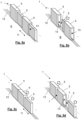
- Figure 4a shows the platform door 1 previously displayed in Figure 1 but in an opening position B wherein passageways 7 are defined between mobile panels 5, for example for accessing the doors of the train 4 parked at the platform 3 as will be described later.
- Some mobile panels 5 can be seen partially overlapped with the adjacent mobile panels 5 thereof, while some mobile panels 5 are completely overlapped with the adjacent mobile panels 5 thereof, the mobile panels 5 with the same panel width w1, w2, being locked. In this way, a great versatility is achieved for forming passageways 7 in the platform door 1 and being able to adapt to different arrangements of train doors 2.
- Figure 4b displays a C-C cross-sectional view of Figure 4a .
- This figure shows that, in the closing position A, at least one mobile panel 5 of each pair of adjacent mobile panels 5, is provided with a hollow 13 for the other mobile panel 5 to pass therethrough, by way of a tunnel that traverses the mobile panel 5, so that one mobile panel 5 can pass through the other one.
- An embodiment is displayed for telescopic mobile panels 5 with two levels. For telescopic mobile panels 5 with three levels, two mobile panels 5 with an eye 13 would be provided, the smaller panel being able to pass through the inside of the eye 13 of the greater one, and a mobile panel 5 that could have no hollow 13 to pass through the eye of the smaller mobile panel 5 with hollow 13.
- Figure 4b shows that the mobile panels 5 of the platform door 1 have a first panel width w1 and a second panel width w2, in an alternate manner and such that a mobile panel 5 can pass through the hollow 13 of another mobile panel 5.
- the height of each mobile panel 5 will also be that which is suitable to be able to carry out the telescopic effect, heights will be typically alternated, the mobile panel 5 with the lesser height being that which must pass through the hollow 13 of another mobile panel 5.
- the mobile panels 5 are mounted on a set of rails 12, which can be one or more, and the mobile panels 5 are in turn provided with traction means 6 designed to move the mobile panels 5 mounted on the rail 12 or rails 12 in an independent manner, these traction means 6 can be for example, drive wheels. Naturally, other traction means 6 that enable the lateral movement of the mobile panels 5 along the platform 3 are also intended.
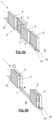
- Figures 5a to 5d display different configurations that can be adopted by the sliding mobile panels 5 of a platform door 1, specifically Figure 5a displays a position wherein the mobile panels 5 are arranged adjacent leaving no space between them; Figure 5b displays the movement of one of the mobile panels 5, a smaller panel, until it is partially inserted inside another mobile panel 5, a greater panel, through the hollow 13 of this greater panel, leaving a passageway 7 between mobile panels 5.
- Figure 5c illustrates the way the smaller mobile panel 5 can completely traverse the greater mobile panel 5, moving in one direction while the greater panel moves in the opposite direction, said greater and smaller panels being exchanged relative to the position previously shown in Figure 5c . Since each mobile panel 5 can move in an independent manner, these can even move away from each other, enabling respective passageways 7 in the way illustrated in Figure 5d .
- Figures 6a and 6b display the sliding mobile panels 5 of another platform door 1 wherein the mobile panels 5 are rigid, can slide laterally and can move in two rows 14, in two parallel planes, such that they can be overlapped with at least the adjacent mobile panels 5 thereof.
- Figure 6a displays the mobile panels 5 in a closing position A of the platform door 1, wherein there is no passageway 7 between mobile panels 5, the mobile panels 5 being arranged in an alternate manner in each row 14, and
- Figure 6b shows the mobile panels 5 in an opening position B of the platform door 1 wherein there is passageway 7 between the mobile panels 5 and the mobile panels 5 are at least overlapped or even exceeding the adjacent mobile panel 5 thereof.
- Figures 7a, 7b and 7c display a system 100 comprising a platform door 1, installed on a platform 3, and a train 4 with one or more train doors 2, in this case three train doors 2, the train 4 being parked at the platform 3.
- Figures 7a and 7b illustrate the system 100 with the platform door 1 in the closing position A.
- the system 100 is provided with detection means 9 for detecting the position of the train doors 2, and control means 10 designed to define the one or more sliding mobile panels 5 of the platform door 1 arranged in front of each train door 2 and actuate these mobile panels 5 to move them and open respective passageways 7 in front of each train door 2 to adopt the opening position B shown in Figure7c .
- Said detection means 9 can obtain information from the train 4 for example from the railway signalling system and can incorporate a transponder designed to directly receive information from the train, as well as detecting the stopping point thereof in the platform 3. It is intended that the detection means 9 comprise a detector of the position of the head 11 of the train 4 parked by the platform 3, such that misalignments in the stopping area of the train due to tolerances can be quickly reported, for a fast preparation of the mobile panels 5. Thus, the detection means 9 can obtain information from the train 4, such as the length and door configuration thereof, and transfer this information to the control means 10 that will define the mobile panels 5 that must be moved to adopt the opening position B.
- the detection means 9 are able to be arranged along the platform 3, or in the platform door 1, for example in the mobile panels 5, and are designed to detect passive signals placed in the train 4 that make it possible to define the position of the train doors 2 when the train parks at the platform 3 so that the control means 10 actuate the mobile panels 5. It is also intended that the detection means 9 can be designed to communicate with active devices arranged in the train 4 such that communication is established between the train 4 and the platform 3 to obtain the door configuration of the train.
- the detection means 9 are also envisaged to be able to be arranged away from the platform 3 and be provided, for example, with a camera directed towards the platform 3, such that the door configuration of the train 4 and the position of the mobile panels 5 can be obtained by processing the images captured to thus define the mobile panels 5 that must be moved for opening the platform door. It is intended that the detection means 9 and the control means 10 are able to be integrated in the same device.
- each mobile panel 5 has dedicated detection means 9 and control means 10 which, for example, detect that upon a train 4 parking at the platform 3, one of the train doors 2 is arranged in front of the mobile panel 5, the mobile panel 5 thus being moved in an autonomous manner between the closing position A, in which it is arranged in front of the train door 2 and the opening position B in which it is away from the train door 2.
- the panel lengths I1 of each mobile panel 5 will be equal to or greater than the train door length I2 of each train door 2 to minimise the number of mobile panels 5 to be moved between the closing position A and the opening position B.
- the train door lengths I2 or the arrangement thereof will not be known beforehand, the required movements of the mobile panels 5 to be able to access the train 4 from the platform 3 will have to be carried out. It is also desirable that the distance between train doors I3 is greater than the panel length I1 to thus minimise the movements of the mobile panels 5.
- Each mobile panel 5 of the platform door 1 is intended to further comprise return means designed to actuate the traction means 6 of each mobile panel 5 to return the mobile panels 5 to the closing position A, such that the passageways 7 that could be between mobile panels 5 are closed and the platform door 1 can get ready to receive another train 4.
- the return means can be a computer programmed to undo the path that has been travelled by each mobile panel 5 between the closing position A and the opening position B, or even simply a rotary encoder that counts the turns of the wheels of each mobile panel 5 during the movement over the rails 12 and actuates the traction means 6 so that the wheels turn the same number of times but in the reverse direction to return the mobile panel 5 to the previous closing position A. It is intended that these return means are also able to be centralised and to allow for instructions to be sent to each one of the mobile panels 5 to return them to the closing position A.
- a method of actuating for opening the platform door comprising the steps of detecting the one or more mobile panels 5 that are arranged in front of each train door 2 once the train 4 is parked by the platform 3; and laterally sliding or moving the one or more mobile panels 5 detected opening respective access passageways 7 in front of each train door 2, as Figure 6b illustrates by means of arrows, adopting the opening position B displayed in Figure 7c .
- the platform door 1 will carry out the step of returning each mobile panel 5 that has been laterally moved until it adopts the previous closing position A of the platform door 1 again, such that the passageways 7 that could be between the platform 3 and the train 4 are closed, thus preventing access to the tracks when there is no train 4 parked by the platform.
- the platform door 1 of the present invention allows for adaptations to a great variety of train door 2 arrangements, without requiring the adaptation or pre-programming to be made in advance, moving the mobile panels 5 thereof as appropriate. Therefore, if the train 4 arriving to the platform 3 has another number and arrangement of train doors 2, such as the train 4 displayed in Figures 8a, 8b and 8c , the train 4 displayed in Figures 9a and 9b or the train 4 displayed in Figures 10a y 10b , the detection means 9 for detecting the position of the train doors 2 will allow actuating and moving the required mobile panels 5 to open respective passageways 7 in front of each train door 2 to adopt the opening position B and thus, to be able to access the train doors 2 from the platform, and subsequently return the mobile panels 5 to the initial position thereof closing the passageways 7 and returning to the closing position A again pending the arrival of a new train 4.
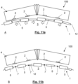
- FIG. 11a and 11b display another embodiment of a platform door 1 of the present invention arranged in a curve, Figure 10a illustrating the closing position A and Figure 11b illustrating the opening position B.
Landscapes
- Engineering & Computer Science (AREA)
- Transportation (AREA)
- Mechanical Engineering (AREA)
- Platform Screen Doors And Railroad Systems (AREA)
- Power-Operated Mechanisms For Wings (AREA)
- Wing Frames And Configurations (AREA)
- Gates (AREA)
Abstract
Description
- The platform door of the present invention is of the type which enables the platform to be separated from the track area in which trains transit and park, and form passageways to access the train doors of a parked train.
- In a railway system consisting of a set of train stations and a set of trains transiting between the stations, it is important that the boarding and alighting of passengers from trains parking at each station is carried out in a very agile manner in order to avoid accumulating delays that would affect the overall operation of the train service. Therefore, it is crucial that after the arrival of a train at a platform, passengers are already close to the track area and, after the train has stopped and the train doors have been quickly opened, the interchange between passengers alighting and boarding can be carried out.
- In order for the passengers to be located on the platform close to the parking area of the train, platform doors are typically used, which allow the passengers to be located safely very near the area where the train doors will be situated, without the danger of falling into the track area, since these platform doors are provided with closed doors that only open when a train is parked at the platform.
- Normally, platform doors are provided by way of a barrier with a set of doors, normally sliding doors, which once a train is parked, allow the opening thereof forming passageways in correspondence with the train doors, thus allowing the passengers to exit and enter the train. For example, document
EP1964747 describes one of these platform doors. - However, this type of platform door exhibits the drawback that the position of the doors is fixed, so that they can only be used in stations in which trains with doors of the same composition and configuration transit, or with coinciding door arrangements. This entails that the use thereof is very difficult in stations in which trains with different composition and configuration stop. This drawback can even entail that the train fleet cannot be renewed if the new trains have a different door arrangement without replacing the doors, a progressive renewal of trains not being possible as the same train doors cannot be used in old and new trains.
- In addition, it must be taken into account that trains exhibit a tolerance regarding the breaking distance, so that it cannot be unequivocally established where the train doors will be arranged after the train stops. Therefore, in order to allow a passageway from the train doors regardless of the stopping position of the train, the platform doors must be oversized taking into account this tolerance. The oversizing of the doors implies that these will be of greater size, greater weight and therefore, it means greater opening and closing times as the doors have to travel a greater distance between the opening and the closing position thereof, in addition to being more difficult to control. This drawback can be solved using faster means for closing and opening the doors. However, this makes the doors even more difficult to control, as they will have to reach high speeds especially when they are oversized.
- However, even if the doors are oversized, this does not prevent the train doors from not being correctly aligned with the platform doors due to braking tolerances, meaning that passengers will not be able to exit or enter the train and the train will have to be moved, with the consequent loss of time, which may affect the overall service of the railway system.
- To solve this problem, platform doors such as those described in document
WO201273658 - It is therefore an object of the present invention to disclose a platform door that allows the use thereof with different train models, with different door arrangement and sizes, and that further achieves optimal opening and closing times after the train stops regardless of the breaking position of the train.
- The platform door for accessing train doors from a platform of the present invention is of the type comprising a plurality of sliding mobile panels that can slide horizontally along the platform, i.e., laterally, in an independent manner by means of respective traction means.
- Essentially, the platform door is characterised in that each mobile panel has a fixed panel length and is designed to slide laterally and be arranged adjacent to other mobile panels adopting a closing position leaving no passageway between mobile panels, i.e., the adjacent panels touching each other or leaving a negligible space between them, and each mobile panel being further designed to slide laterally and at least partially overlap with one of the adjacent mobile panels thereof, adopting an opening position defining passageways between mobile panels for accessing train doors, such that the mobile panels of the platform door can adopt different positions and thus leave different passageways between mobile panels, even with different passageway sizes to thus adapt to the arrangements of the doors of a train that is parked in the platform, in the opening position, and allow users to board and alight comfortably and easily, and the mobile panels being able to adopt a position in which the mobile panels do not allow a passageway, in the closing position, to prevent the users from accessing the tracks when there is no train parked at the platform. In this way, the interoperability of trains with different composition and configuration is facilitated, since the platform doors can be adapted to the train door configuration of each type of train, configuration that can vary between train companies or even between train models of the same company or that will vary depending on the type of cars forming each train.
- In a variant embodiment, from the closing position, the mobile panels are designed to at least partially and telescopically overlap with one of the adjacent mobile panels thereof, such that smaller size ones can be introduced inside larger size ones, generally in the shape of an arch defining a hollow, by way of a tunnel, in which the adjacent mobile panel with smaller size can at least be partially housed.
- In a variant embodiment, from the closing position, each mobile panel is designed to telescopically and completely overlap with one of the adjacent mobile panels thereof, such that a smaller size panel can be completely concealed inside a larger size panel.
- In a variant embodiment, from the closing position, each mobile panel is designed to exceed, i.e., pass through one of the adjacent panels thereof, two adjacent mobile panels being able to entirely cross each other, thus enabling two adjacent mobile panels to exchange position.
- In a variant embodiment, the panel length of each mobile panel is equal, such that in the closing position, all the mobile panels exhibit a homogeneous display of the platform door, further enabling, when the mobile panels are telescopic, a mobile panel to be able to be inserted and perfectly adjusted inside another mobile panel, during the opening position or during the transitions between the closing position and the opening position.
- In a variant embodiment, in the closing position, at least one mobile panel of each pair of adjacent mobile panels is provided with a hollow, which defines a tunnel that passes through the inside of the mobile panel, for the other mobile panel to pass therethrough.
- In a variant embodiment, in the closing position, adjacent mobile panels have a first panel width and a second panel width in an alternate manner, such that the mobile panels are telescopic two by two.
- In a variant embodiment, the platform door comprises at least one rail on which mobile panels of the platform door are mounted, the traction means being designed to move the mobile panels mounted on the rail in an independent manner. Naturally, the one or more rails may be mounted on the platform floor, so that the mobile panels will be held by the platform floor, or with the platform ceiling, so that the mobile panels will be held by the platform ceiling, i.e., the mobile panels will be hanging from the platform ceiling. It is also intended that the rails are distributed between the platform floor and the ceiling, such that some mobile panels are held on the floor and others will be held in the platform ceiling. In this way, each mobile panel will be able to move independently from the rest of mobile panels and, in turn, between the closing position and the opening position, thus adopting the configurations required to adapt to the configuration of the train doors of a train that is parked at the platform. These traction means can be wheels actuated by motors that move the mobile panels which in turn can be directed as appropriate, preferably in a straight line since they are mounted on straight rails. Naturally, it is intended that there are different sets of rails if a mobile panel must pass through another adjacent mobile panel, or exceed another mobile panel in a parallel plane. Other traction means are envisaged such as electromagnetic movement means.
- In a variant embodiment, each mobile panel comprises return means designed for actuating the traction means of each mobile panel to return to the closing position from the opening position. These return means can memorise the original position or the movement performed by each mobile panel between the closing position and the opening position to undo this movement by actuating the traction means in a timely manner, the mobile panels thus quickly returning to the closing position.
- A system is also disclosed comprising a platform door installed on a platform, and a train with one or more train doors parked at the platform, the system being provided with detection means for detecting the position of the train doors of the train, and control means designed for defining the one or more mobile panels of the platform door that are arranged in front of each train door and actuate these mobile panels to open respective passageways in front of each train door to adopt the opening position.
- In a variant embodiment, the panel length of each mobile panel is equal to or greater than the train door length of each train door, i.e., the width or free passageway thereof, such that only one or two panels must be moved per train door for opening the platform door.
- In one variant embodiment, the detection means comprise a detector of the position of the head of the train parked by the platform, such that misalignments in the stopping area of the train due to tolerances can be quickly reported, for a fast preparation of the mobile panels.
- In a variant embodiment, the distance between train doors is greater than the panel length, such that several mobile panels can be arranged between train doors, the mobile panels being able to have a smaller size, facilitating the movement and modularity thereof.
- A method of actuating the platform door of the system described is also disclosed, from a closing position, in which there are no passageways between the mobile panels, comprising, upon the arrival of a train provided with train doors, the steps of detecting the one or more mobile panels that are arranged in front of each train door once the train is parked on the platform; and laterally slide the one or more mobile panels detected, opening respective access passageways before each train door, adopting an opening position. In an embodiment of interest, the method further comprises after adopting the opening position, the step of returning each panel that has been laterally moved until it adopts the previous closing position of the platform door again.
- As a complement to the description provided herein, and for the purpose of helping to make the features of the invention more readily understandable, said specification is accompanied by a set of drawings, which by way of illustration and not limitation, represent the following:
-
Figs. 1, 2 and 3 show top views of platform doors according to the present invention in the closing position; -
Fig. 4a shows the platform door ofFig. 1 in an opening position; -
Fig. 4b shows a cross-sectional view of the platform door ofFig. 4a ; -
Figs. 5a to 5d show lateral movements for a type of mobile panels of a platform door according to the present invention; -
Figs. 6a to 6b show lateral movements for another type of mobile panels of a platform door according to the present invention; -
Figs. 7a to 7c show a first system comprising a train and a platform door in the closing position and in the opening position; -
Figs. 8a to 8c show a second system comprising a train and a platform door in the closing position and in the opening position; -
Figs. 9a and 9b show a third system comprising another train and the platform door in the closing position and the opening position; -
Figs. 10a and 10b show a fourth system comprising another train and the platform door in the closing position and the opening position; and -
Figs. 11a and 11 b show a curved platform door according to the present invention in the closing position and the opening position. -
Figures 1, 2 and 3 show platform doors 1 for accessing thetrain door 2 from aplatform 3, the platform door comprising a plurality of slidingmobile panels 5 that can slide laterally in an independent manner by means of respective traction means 6. The figures show that eachmobile panel 5 is rigid and has a fixedpanel length 11, preferably the panel length I1 of eachpanel 5 is equal, and is arranged adjacent to othermobile panels 5 adopting a closing position A leaving no passageway betweenmobile panels 5, and eachmobile panel 5 being further designed to slide laterally and at least partially overlap with one of the adjacentmobile panels 5 thereof, thus being able to adopt an opening position B and definingpassageways 7 betweenmobile panels 5 for accessing thetrain doors 4 parked at theplatform 3. - The
platform door 1 represented inFigures 1 and 2 is formed by telescopicmobile panels 5, designed to at least partially and telescopically overlap with one of the adjacentmobile panels 5 thereof, such that themobile panels 5 can slide and form a single body with at least the adjacentmobile panel 5, one penetrating inside the other. -
Figure 1 shows an embodiment with two levels, i.e., two panel widths w1, w2, such that themobile panels 5 can telescopically overlap and form a single body every twomobile panels 5, whileFigure 2 shows an embodiment with three levels, i.e., three panel widths, such that themobile panels 5 can slide and form a single body in groups of three. Naturally,other platform doors 1 with several telescopic levels can be envisaged, such that themobile panels 5 can be joined together and be combined with the adjacentmobile panels 5 thereof. - It is also intended that the
mobile panels 5 are arranged inseveral rows 14, in the manner illustrated inFigure 3 for example, wherein themobile panels 5 are arranged in tworows 14, and that they can be arranged adjacent to othermobile panels 5 of theother row 14, adopting a closing position A leaving no passageway betweenmobile panels 5. As can be seen, in the closing position A themobile panels 5 are arranged one after the other in a continuous manner, for example in alternatingrows 14 leaving no passageway betweenmobile panels 5. In addition, each slidingmobile panel 5 is designed to slide laterally and at least partially overlap with one of the adjacentmobile panels 5 thereof, in this case, the adjacent panel in theother row 14, thus being able to adopt an opening position B and definingpassageways 7 betweenmobile panels 5 for accessing thetrain doors 4 parked at theplatform 3. Naturally, although not illustrated by these figures, it is intended that themobile panels 5 are even be able to exceed the adjacentmobile panel 5 thereof to adopt the closing position A or opening position B as appropriate, thus conferring great flexibility in the arrangement ofmobile panels 5. The flexibility in the arrangement ofmobile panels 5 being a feature that is shared by all the displayed embodiments ofplatform door 1 is highlighted. Although thisFigure 3 displays all themobile panels 5 having asame panel length 11, it is also intended that the panels are able to have different panel lengths I1 as appropriate, for example, with a greater panel length I1 in the endmobile panels 5 and a smaller panel length I1 in the centralmobile panels 5, thus facilitating the quick movement of the central mobile panels. In this case, themobile panel 5 height can be the same. - In the telescopic
mobile panels 5 displayed inFigures. 1 and 2 , for example, eachmobile panel 5 is designed to telescopically and completely overlap with one of the adjacentmobile panels 5 thereof from the closing position A. From the closing position A, it is also intended that eachmobile panel 5 is designed not only to overlap with one of the adjacentmobile panels 5 thereof, but even so that amobile panel 5 exceeds one of the adjacentmobile panels 5 thereof, different combinations being thus possible betweenmobile panels 5 and definingpassageways 7 as appropriate, such that when atrain 4 parks at aplatform 3 thepassageways 7 of thetrain door 1 coincide with thetrain doors 2, thus allowing passengers to access and exit thetrain 4. -
Figure 4a shows theplatform door 1 previously displayed inFigure 1 but in an opening position B whereinpassageways 7 are defined betweenmobile panels 5, for example for accessing the doors of thetrain 4 parked at theplatform 3 as will be described later. Somemobile panels 5 can be seen partially overlapped with the adjacentmobile panels 5 thereof, while somemobile panels 5 are completely overlapped with the adjacentmobile panels 5 thereof, themobile panels 5 with the same panel width w1, w2, being locked. In this way, a great versatility is achieved for formingpassageways 7 in theplatform door 1 and being able to adapt to different arrangements oftrain doors 2. -
Figure 4b displays a C-C cross-sectional view ofFigure 4a . This figure shows that, in the closing position A, at least onemobile panel 5 of each pair of adjacentmobile panels 5, is provided with a hollow 13 for the othermobile panel 5 to pass therethrough, by way of a tunnel that traverses themobile panel 5, so that onemobile panel 5 can pass through the other one. An embodiment is displayed for telescopicmobile panels 5 with two levels. For telescopicmobile panels 5 with three levels, twomobile panels 5 with aneye 13 would be provided, the smaller panel being able to pass through the inside of theeye 13 of the greater one, and amobile panel 5 that could have no hollow 13 to pass through the eye of the smallermobile panel 5 with hollow 13. -
Figure 4b shows that themobile panels 5 of theplatform door 1 have a first panel width w1 and a second panel width w2, in an alternate manner and such that amobile panel 5 can pass through the hollow 13 of anothermobile panel 5. The height of eachmobile panel 5 will also be that which is suitable to be able to carry out the telescopic effect, heights will be typically alternated, themobile panel 5 with the lesser height being that which must pass through the hollow 13 of anothermobile panel 5. - In addition, the
mobile panels 5 are mounted on a set ofrails 12, which can be one or more, and themobile panels 5 are in turn provided with traction means 6 designed to move themobile panels 5 mounted on therail 12 orrails 12 in an independent manner, these traction means 6 can be for example, drive wheels. Naturally, other traction means 6 that enable the lateral movement of themobile panels 5 along theplatform 3 are also intended. -
Figures 5a to 5d display different configurations that can be adopted by the slidingmobile panels 5 of aplatform door 1, specificallyFigure 5a displays a position wherein themobile panels 5 are arranged adjacent leaving no space between them;Figure 5b displays the movement of one of themobile panels 5, a smaller panel, until it is partially inserted inside anothermobile panel 5, a greater panel, through the hollow 13 of this greater panel, leaving apassageway 7 betweenmobile panels 5.Figure 5c illustrates the way the smallermobile panel 5 can completely traverse the greatermobile panel 5, moving in one direction while the greater panel moves in the opposite direction, said greater and smaller panels being exchanged relative to the position previously shown inFigure 5c . Since eachmobile panel 5 can move in an independent manner, these can even move away from each other, enablingrespective passageways 7 in the way illustrated inFigure 5d . -
Figures 6a and 6b display the slidingmobile panels 5 of anotherplatform door 1 wherein themobile panels 5 are rigid, can slide laterally and can move in tworows 14, in two parallel planes, such that they can be overlapped with at least the adjacentmobile panels 5 thereof.Figure 6a displays themobile panels 5 in a closing position A of theplatform door 1, wherein there is nopassageway 7 betweenmobile panels 5, themobile panels 5 being arranged in an alternate manner in eachrow 14, andFigure 6b shows themobile panels 5 in an opening position B of theplatform door 1 wherein there ispassageway 7 between themobile panels 5 and themobile panels 5 are at least overlapped or even exceeding the adjacentmobile panel 5 thereof. -
Figures 7a, 7b and 7c display asystem 100 comprising aplatform door 1, installed on aplatform 3, and atrain 4 with one ormore train doors 2, in this case threetrain doors 2, thetrain 4 being parked at theplatform 3.Figures 7a and 7b illustrate thesystem 100 with theplatform door 1 in the closing position A. Thesystem 100 is provided with detection means 9 for detecting the position of thetrain doors 2, and control means 10 designed to define the one or more slidingmobile panels 5 of theplatform door 1 arranged in front of eachtrain door 2 and actuate thesemobile panels 5 to move them and openrespective passageways 7 in front of eachtrain door 2 to adopt the opening position B shown inFigure7c . Said detection means 9 can obtain information from thetrain 4 for example from the railway signalling system and can incorporate a transponder designed to directly receive information from the train, as well as detecting the stopping point thereof in theplatform 3. It is intended that the detection means 9 comprise a detector of the position of thehead 11 of thetrain 4 parked by theplatform 3, such that misalignments in the stopping area of the train due to tolerances can be quickly reported, for a fast preparation of themobile panels 5. Thus, the detection means 9 can obtain information from thetrain 4, such as the length and door configuration thereof, and transfer this information to the control means 10 that will define themobile panels 5 that must be moved to adopt the opening position B. Naturally, it is also intended that the detection means 9 are able to be arranged along theplatform 3, or in theplatform door 1, for example in themobile panels 5, and are designed to detect passive signals placed in thetrain 4 that make it possible to define the position of thetrain doors 2 when the train parks at theplatform 3 so that the control means 10 actuate themobile panels 5. It is also intended that the detection means 9 can be designed to communicate with active devices arranged in thetrain 4 such that communication is established between thetrain 4 and theplatform 3 to obtain the door configuration of the train. It is also intended that the detection means 9 are also envisaged to be able to be arranged away from theplatform 3 and be provided, for example, with a camera directed towards theplatform 3, such that the door configuration of thetrain 4 and the position of themobile panels 5 can be obtained by processing the images captured to thus define themobile panels 5 that must be moved for opening the platform door. It is intended that the detection means 9 and the control means 10 are able to be integrated in the same device. It is also intended that eachmobile panel 5 has dedicated detection means 9 and control means 10 which, for example, detect that upon atrain 4 parking at theplatform 3, one of thetrain doors 2 is arranged in front of themobile panel 5, themobile panel 5 thus being moved in an autonomous manner between the closing position A, in which it is arranged in front of thetrain door 2 and the opening position B in which it is away from thetrain door 2. - After moving the defined
mobile panels 5, represented by respective arrows in dashed lines, and upon adopting an opening position B shown inFigure 7c , the passengers can board and alight from thetrain 4. Preferably, the panel lengths I1 of eachmobile panel 5 will be equal to or greater than the train door length I2 of eachtrain door 2 to minimise the number ofmobile panels 5 to be moved between the closing position A and the opening position B. However, since oftentimes the train door lengths I2 or the arrangement thereof will not be known beforehand, the required movements of themobile panels 5 to be able to access thetrain 4 from theplatform 3 will have to be carried out. It is also desirable that the distance between train doors I3 is greater than the panel length I1 to thus minimise the movements of themobile panels 5. However, as explained before, if the type oftrain 4 and the arrangement oftrain doors 2 or the distance between train doors I3 is not known, the required movements of themobile panels 5 to openpassageways 7 and be able to access thetrain 4 from theplatform 3 will have to be carried out. - Each
mobile panel 5 of theplatform door 1 is intended to further comprise return means designed to actuate the traction means 6 of eachmobile panel 5 to return themobile panels 5 to the closing position A, such that thepassageways 7 that could be betweenmobile panels 5 are closed and theplatform door 1 can get ready to receive anothertrain 4. The return means can be a computer programmed to undo the path that has been travelled by eachmobile panel 5 between the closing position A and the opening position B, or even simply a rotary encoder that counts the turns of the wheels of eachmobile panel 5 during the movement over therails 12 and actuates the traction means 6 so that the wheels turn the same number of times but in the reverse direction to return themobile panel 5 to the previous closing position A. It is intended that these return means are also able to be centralised and to allow for instructions to be sent to each one of themobile panels 5 to return them to the closing position A. - Thus, upon the arrival of a
train 4 as illustrated inFigures 7a and 7b in which theplatform door 1 is in a closing position A, with nopassageway 7 between themobile panels 5, and wherein thetrain 4 is provided withtrain doors 2, a method of actuating for opening the platform door will be performed comprising the steps of detecting the one or moremobile panels 5 that are arranged in front of eachtrain door 2 once thetrain 4 is parked by theplatform 3; and laterally sliding or moving the one or moremobile panels 5 detected openingrespective access passageways 7 in front of eachtrain door 2, asFigure 6b illustrates by means of arrows, adopting the opening position B displayed inFigure 7c . - Naturally, after adopting the opening position B, and preferably before the
train 4 leaves theplatform 3, for example, once thetrain doors 2 are closed, or while thetrain doors 2 are being closed, theplatform door 1 will carry out the step of returning eachmobile panel 5 that has been laterally moved until it adopts the previous closing position A of theplatform door 1 again, such that thepassageways 7 that could be between theplatform 3 and thetrain 4 are closed, thus preventing access to the tracks when there is notrain 4 parked by the platform. - The
platform door 1 of the present invention allows for adaptations to a great variety oftrain door 2 arrangements, without requiring the adaptation or pre-programming to be made in advance, moving themobile panels 5 thereof as appropriate. Therefore, if thetrain 4 arriving to theplatform 3 has another number and arrangement oftrain doors 2, such as thetrain 4 displayed inFigures 8a, 8b and 8c , thetrain 4 displayed inFigures 9a and 9b or thetrain 4 displayed inFigures 10a y10b , the detection means 9 for detecting the position of thetrain doors 2 will allow actuating and moving the requiredmobile panels 5 to openrespective passageways 7 in front of eachtrain door 2 to adopt the opening position B and thus, to be able to access thetrain doors 2 from the platform, and subsequently return themobile panels 5 to the initial position thereof closing thepassageways 7 and returning to the closing position A again pending the arrival of anew train 4. - Although the
mobile panels 5 of theplatform door 1 are sliding and move in a straight lateral line in the previous embodiments, according to the shape of eachplatform 3, it is intended that theplatform door 1 can have other shapes. For example,Figures. 11a and 11b display another embodiment of aplatform door 1 of the present invention arranged in a curve,Figure 10a illustrating the closing position A andFigure 11b illustrating the opening position B.
Claims (15)
- A platform door (1) for accessing train doors (2) from a platform (3), the platform door comprising a plurality of sliding mobile panels (5) that can slide laterally in an independent manner by means of respective traction means (6), characterised in that each mobile panel (5) has a fixed panel length (11) and is designed to slide laterally and be arranged adjacent to other mobile panels (5) adopting a closing position (A) leaving no passageway (7) between panels, and each mobile panel (5) being further suitable to slide laterally and at least partially overlap with one of the adjacent mobile panels (5) thereof, adopting an opening position (B) defining passageways (7) between mobile panels (5) for accessing train doors (2).
- The platform door (1) according to the preceding claim, characterised in that, from the closing position (A), the mobile panels (5) are designed to at least partially and telescopically overlap with one of the adjacent mobile panels (5) thereof.
- The platform door (1), according to the preceding claim, characterised in that, from the closing position (A), the mobile panels (5) are designed to telescopically and completely overlap with one of the adjacent mobile panels (5) thereof.
- The platform door (1), according to any one of the preceding claims, characterised in that, from the closing position (A), each mobile panel (5) is designed to exceed one of the adjacent mobile panels (5) thereof.
- The platform door (1) according to any one of the preceding claims, characterised in that the panel length (11) of each mobile panel (5) is equal.
- The platform door (1) according to any one of the preceding claims, characterised in that, in the closing position (A), at least one mobile panel (5) of each pair of adjacent mobile panels (5) is provided with a hollow (13) for the other mobile panel (5) to pass therethrough.
- The platform door (1) according to the preceding claim, characterised in that, in the closing position (A), adjacent mobile panels (5) have a first panel width (w1) and a second panel width (w2) in an alternate manner.
- The platform door (1) according to any one of the preceding claims, characterised in that it comprises at least one rail (12) on which the mobile panels (5) of the platform door are mounted, the traction means (6) being designed to move the mobile panels (5) mounted on the rail in an independent manner.
- The platform door (1) according to any one of the preceding claims, characterised in that each mobile panel (5) comprises return means designed for actuating the traction means (6) of each mobile panel (5) to return to the closing position (A) from the opening position (B).
- A system (100) comprising a platform door (1) according to any one of the preceding claims, installed on a platform (3), and a train (4) with one or more train doors (2) parked at the platform, the system being provided with detection means (9) for detecting the position of the train doors of the train, and control means (10) designed to define the one or more mobile panels (5) of the platform door arranged in front of each train door and actuate these mobile panels (5) to open respective passageways (7) in front of each train door (2) to adopt the opening position (B).
- The system (100), according to the preceding claim, characterised in that the panel length (11) of each mobile panel (5) is equal to or greater than the train door length (12) of each train door (2).
- The system (100), according to any one of claims 10 to 11, characterised in that the detection means (9) comprise a detector of the position of the head (11) of the train (4) parked by the platform (3).
- The system (100), according to any one of claims 10 to 12, characterised in that the distance between train doors (13) is greater than the panel length (11).
- A method for actuating the platform door (1) of the system according to any one of claims 10 to 13, from a closing position (A), wherein there are no passageways (7) between the mobile panels (5), comprising, upon the arrival of a train (4) provided with train doors (2), the steps of:- detecting the one or more mobile panels (5) that are arranged in front of each train door (2) after the train (4) has parked by the platform; and- slide laterally the mobile panels (5) detected opening respective access passageways (7) before each train door (2), adopting an opening position (B).
- The method according to the preceding claim, characterised in that it comprises, after adopting an opening position (B), the step of returning each mobile panel (5) that has been moved laterally until it adopts the previous closing position (A) of the platform door (1) again.
Priority Applications (8)
| Application Number | Priority Date | Filing Date | Title |
|---|---|---|---|
| EP22382537.3A EP4286235B1 (en) | 2022-06-03 | 2022-06-03 | Platform door, system comprising the platform door and method of actuating the platform door |
| ES22382537T ES3070357T3 (en) | 2022-06-03 | 2022-06-03 | Platform door, system comprising the platform door and platform door operating procedure |
| US18/870,232 US20250340224A1 (en) | 2022-06-03 | 2023-06-02 | Platform door, system comprising the platform door and method of actuating the platform door |
| PCT/ES2023/070368 WO2023233061A1 (en) | 2022-06-03 | 2023-06-02 | Platform door, system comprising the platform door and method of actuating the platform door |
| CN202380044710.1A CN119343285A (en) | 2022-06-03 | 2023-06-02 | Platform door, system comprising the platform door and method of actuating the platform door |
| CA3254763A CA3254763A1 (en) | 2022-06-03 | 2023-06-02 | Platform door, system comprising the platform door and method of actuating the platform door |
| CL2024003544A CL2024003544A1 (en) | 2022-06-03 | 2024-11-19 | Platform door, system comprising the platform door and operating procedure |
| CONC2024/0016699A CO2024016699A2 (en) | 2022-06-03 | 2024-12-04 | Platform door, system comprising the platform door and a method of operating the platform door |
Applications Claiming Priority (1)
| Application Number | Priority Date | Filing Date | Title |
|---|---|---|---|
| EP22382537.3A EP4286235B1 (en) | 2022-06-03 | 2022-06-03 | Platform door, system comprising the platform door and method of actuating the platform door |
Publications (3)
| Publication Number | Publication Date |
|---|---|
| EP4286235A1 true EP4286235A1 (en) | 2023-12-06 |
| EP4286235C0 EP4286235C0 (en) | 2026-03-04 |
| EP4286235B1 EP4286235B1 (en) | 2026-03-04 |
Family
ID=82656343
Family Applications (1)
| Application Number | Title | Priority Date | Filing Date |
|---|---|---|---|
| EP22382537.3A Active EP4286235B1 (en) | 2022-06-03 | 2022-06-03 | Platform door, system comprising the platform door and method of actuating the platform door |
Country Status (8)
| Country | Link |
|---|---|
| US (1) | US20250340224A1 (en) |
| EP (1) | EP4286235B1 (en) |
| CN (1) | CN119343285A (en) |
| CA (1) | CA3254763A1 (en) |
| CL (1) | CL2024003544A1 (en) |
| CO (1) | CO2024016699A2 (en) |
| ES (1) | ES3070357T3 (en) |
| WO (1) | WO2023233061A1 (en) |
Citations (8)
| Publication number | Priority date | Publication date | Assignee | Title |
|---|---|---|---|---|
| EP1964747A1 (en) | 2005-07-14 | 2008-09-03 | Kaba Gilgen AG | Sliding door construction for platforms and method for their fitting |
| WO2008149246A1 (en) * | 2007-06-06 | 2008-12-11 | O.C.L.A.P. S.R.L. | Platform gate for train stations |
| WO2012073658A1 (en) | 2010-12-03 | 2012-06-07 | 国立大学法人東京大学 | Associating device of loading/unloading position variable platform door with train and structure determination device of loading/unloading position variable platform door |
| JP2013199153A (en) * | 2012-03-23 | 2013-10-03 | Kyosan Electric Mfg Co Ltd | Platform fence |
| WO2019245453A1 (en) * | 2018-06-20 | 2019-12-26 | St Engineering Electronics Ltd | Variable pitch platform screens or sliding doors in transit stations |
| WO2021112476A1 (en) * | 2019-12-06 | 2021-06-10 | 주식회사 보성알앤디 | Multi-folding sliding screen door device |
| CN111852249B (en) * | 2020-07-30 | 2021-08-27 | 成都唐源电气股份有限公司 | Front-back staggered high-speed rail platform door control method |
| CN114174143A (en) * | 2019-07-24 | 2022-03-11 | 萨福有限责任公司 | Platform shield |
-
2022
- 2022-06-03 EP EP22382537.3A patent/EP4286235B1/en active Active
- 2022-06-03 ES ES22382537T patent/ES3070357T3/en active Active
-
2023
- 2023-06-02 US US18/870,232 patent/US20250340224A1/en active Pending
- 2023-06-02 WO PCT/ES2023/070368 patent/WO2023233061A1/en not_active Ceased
- 2023-06-02 CA CA3254763A patent/CA3254763A1/en active Pending
- 2023-06-02 CN CN202380044710.1A patent/CN119343285A/en active Pending
-
2024
- 2024-11-19 CL CL2024003544A patent/CL2024003544A1/en unknown
- 2024-12-04 CO CONC2024/0016699A patent/CO2024016699A2/en unknown
Patent Citations (8)
| Publication number | Priority date | Publication date | Assignee | Title |
|---|---|---|---|---|
| EP1964747A1 (en) | 2005-07-14 | 2008-09-03 | Kaba Gilgen AG | Sliding door construction for platforms and method for their fitting |
| WO2008149246A1 (en) * | 2007-06-06 | 2008-12-11 | O.C.L.A.P. S.R.L. | Platform gate for train stations |
| WO2012073658A1 (en) | 2010-12-03 | 2012-06-07 | 国立大学法人東京大学 | Associating device of loading/unloading position variable platform door with train and structure determination device of loading/unloading position variable platform door |
| JP2013199153A (en) * | 2012-03-23 | 2013-10-03 | Kyosan Electric Mfg Co Ltd | Platform fence |
| WO2019245453A1 (en) * | 2018-06-20 | 2019-12-26 | St Engineering Electronics Ltd | Variable pitch platform screens or sliding doors in transit stations |
| CN114174143A (en) * | 2019-07-24 | 2022-03-11 | 萨福有限责任公司 | Platform shield |
| WO2021112476A1 (en) * | 2019-12-06 | 2021-06-10 | 주식회사 보성알앤디 | Multi-folding sliding screen door device |
| CN111852249B (en) * | 2020-07-30 | 2021-08-27 | 成都唐源电气股份有限公司 | Front-back staggered high-speed rail platform door control method |
Also Published As
| Publication number | Publication date |
|---|---|
| EP4286235C0 (en) | 2026-03-04 |
| ES3070357T3 (en) | 2026-06-15 |
| CN119343285A (en) | 2025-01-21 |
| WO2023233061A1 (en) | 2023-12-07 |
| CA3254763A1 (en) | 2025-03-18 |
| CO2024016699A2 (en) | 2024-12-09 |
| CL2024003544A1 (en) | 2025-04-11 |
| US20250340224A1 (en) | 2025-11-06 |
| EP4286235B1 (en) | 2026-03-04 |
Similar Documents
| Publication | Publication Date | Title |
|---|---|---|
| EP1789298B2 (en) | Method and device for the coordinate operation of vehicle doors of railborne or guided vehicles and corresponding platform guiding systems, especially platform doors | |
| RU2460656C2 (en) | Railway station platform gate | |
| US9266538B2 (en) | Platform door system, method for operating a platform door system and door frame for a platform door system | |
| TWI284096B (en) | Movable fence and method of opening/closing movable fence | |
| CN111852249B (en) | Front-back staggered high-speed rail platform door control method | |
| CA2646579C (en) | Automatic cable car facility | |
| EP3124350B1 (en) | Door control system and methods for the joint control of vehicle and platform doors | |
| CN111775965B (en) | Underlying-driven split-level high-speed rail platform door | |
| CA2967838C (en) | Aerial cableway system | |
| JP2009530175A (en) | Platform shielding door | |
| EP4286235B1 (en) | Platform door, system comprising the platform door and method of actuating the platform door | |
| AT505345A1 (en) | TRANSPORT SYSTEM FOR MEDIUM DISTANCES | |
| JPH11291897A (en) | Platform switchgear | |
| RU2701367C1 (en) | Guard to prevent falling of passengers from platforms of underground and railway | |
| TW202012228A (en) | Variable Pitch Platform Screens Or Sliding Doors System In Transit Stations | |
| CN116537663A (en) | Control system and method for platform screen door | |
| EP4079993B1 (en) | Railway station roof with integrated passenger guidance system | |
| CN112498371A (en) | Urban rail transit train operation method | |
| KR102853674B1 (en) | Platform screen door system for different rail vehicle | |
| CN114394115B (en) | Multi-vehicle type universal rail platform door safety positioning system and control method | |
| HK40074529A (en) | An adaptable railway station roof and integrated passenger guidance system thereof | |
| CN118182539A (en) | A passenger platform control system and method | |
| AT505676A2 (en) | Digital pulse transmission system for infra red remote control - has quartz oscillators in transmitter and receiver | |
| DE19811054A1 (en) | Station for public transport vehicles | |
| HK1033566B (en) | Flexible platform door system |
Legal Events
| Date | Code | Title | Description |
|---|---|---|---|
| PUAI | Public reference made under article 153(3) epc to a published international application that has entered the european phase |
Free format text: ORIGINAL CODE: 0009012 |
|
| STAA | Information on the status of an ep patent application or granted ep patent |
Free format text: STATUS: THE APPLICATION HAS BEEN PUBLISHED |
|
| AK | Designated contracting states |
Kind code of ref document: A1 Designated state(s): AL AT BE BG CH CY CZ DE DK EE ES FI FR GB GR HR HU IE IS IT LI LT LU LV MC MK MT NL NO PL PT RO RS SE SI SK SM TR |
|
| STAA | Information on the status of an ep patent application or granted ep patent |
Free format text: STATUS: REQUEST FOR EXAMINATION WAS MADE |
|
| 17P | Request for examination filed |
Effective date: 20240531 |
|
| RBV | Designated contracting states (corrected) |
Designated state(s): AL AT BE BG CH CY CZ DE DK EE ES FI FR GB GR HR HU IE IS IT LI LT LU LV MC MK MT NL NO PL PT RO RS SE SI SK SM TR |
|
| GRAP | Despatch of communication of intention to grant a patent |
Free format text: ORIGINAL CODE: EPIDOSNIGR1 |
|
| STAA | Information on the status of an ep patent application or granted ep patent |
Free format text: STATUS: GRANT OF PATENT IS INTENDED |
|
| INTG | Intention to grant announced |
Effective date: 20251015 |
|
| GRAS | Grant fee paid |
Free format text: ORIGINAL CODE: EPIDOSNIGR3 |
|
| GRAA | (expected) grant |
Free format text: ORIGINAL CODE: 0009210 |
|
| STAA | Information on the status of an ep patent application or granted ep patent |
Free format text: STATUS: THE PATENT HAS BEEN GRANTED |
|
| AK | Designated contracting states |
Kind code of ref document: B1 Designated state(s): AL AT BE BG CH CY CZ DE DK EE ES FI FR GB GR HR HU IE IS IT LI LT LU LV MC MK MT NL NO PL PT RO RS SE SI SK SM TR |
|
| REG | Reference to a national code |
Ref country code: CH Ref legal event code: F10 Free format text: ST27 STATUS EVENT CODE: U-0-0-F10-F00 (AS PROVIDED BY THE NATIONAL OFFICE) Effective date: 20260304 Ref country code: GB Ref legal event code: FG4D |
|
| REG | Reference to a national code |
Ref country code: IE Ref legal event code: FG4D |
|
| REG | Reference to a national code |
Ref country code: DE Ref legal event code: R096 Ref document number: 602022031563 Country of ref document: DE |
|
| U01 | Request for unitary effect filed |
Effective date: 20260331 |
|
| U07 | Unitary effect registered |
Designated state(s): AT BE BG DE DK EE FI FR IT LT LU LV MT NL PT RO SE SI Effective date: 20260408 |
|
| REG | Reference to a national code |
Ref country code: ES Ref legal event code: FG2A Ref document number: 3070357 Country of ref document: ES Kind code of ref document: T3 Effective date: 20260615 |
|
| PG25 | Lapsed in a contracting state [announced via postgrant information from national office to epo] |
Ref country code: RS Free format text: LAPSE BECAUSE OF FAILURE TO SUBMIT A TRANSLATION OF THE DESCRIPTION OR TO PAY THE FEE WITHIN THE PRESCRIBED TIME-LIMIT Effective date: 20260604 |
|
| PG25 | Lapsed in a contracting state [announced via postgrant information from national office to epo] |
Ref country code: PL Free format text: LAPSE BECAUSE OF FAILURE TO SUBMIT A TRANSLATION OF THE DESCRIPTION OR TO PAY THE FEE WITHIN THE PRESCRIBED TIME-LIMIT Effective date: 20260304 |
|
| PG25 | Lapsed in a contracting state [announced via postgrant information from national office to epo] |
Ref country code: GR Free format text: LAPSE BECAUSE OF FAILURE TO SUBMIT A TRANSLATION OF THE DESCRIPTION OR TO PAY THE FEE WITHIN THE PRESCRIBED TIME-LIMIT Effective date: 20260605 |
|
| PG25 | Lapsed in a contracting state [announced via postgrant information from national office to epo] |
Ref country code: NO Free format text: LAPSE BECAUSE OF FAILURE TO SUBMIT A TRANSLATION OF THE DESCRIPTION OR TO PAY THE FEE WITHIN THE PRESCRIBED TIME-LIMIT Effective date: 20260604 |
|
| PG25 | Lapsed in a contracting state [announced via postgrant information from national office to epo] |
Ref country code: HR Free format text: LAPSE BECAUSE OF FAILURE TO SUBMIT A TRANSLATION OF THE DESCRIPTION OR TO PAY THE FEE WITHIN THE PRESCRIBED TIME-LIMIT Effective date: 20260304 |
|
| PGFP | Annual fee paid to national office [announced via postgrant information from national office to epo] |
Ref country code: TR Payment date: 20260603 Year of fee payment: 5 |
|
| U20 | Renewal fee for the european patent with unitary effect paid |
Year of fee payment: 5 Effective date: 20260629 |