EP4286218A1 - Vehicular cab provided with an improved anti-mine seat - Google Patents
Vehicular cab provided with an improved anti-mine seat Download PDFInfo
- Publication number
- EP4286218A1 EP4286218A1 EP23176700.5A EP23176700A EP4286218A1 EP 4286218 A1 EP4286218 A1 EP 4286218A1 EP 23176700 A EP23176700 A EP 23176700A EP 4286218 A1 EP4286218 A1 EP 4286218A1
- Authority
- EP
- European Patent Office
- Prior art keywords
- cab
- seat
- mine
- side walls
- anchorage points
- Prior art date
- Legal status (The legal status is an assumption and is not a legal conclusion. Google has not performed a legal analysis and makes no representation as to the accuracy of the status listed.)
- Pending
Links
Images


Classifications
-
- B—PERFORMING OPERATIONS; TRANSPORTING
- B60—VEHICLES IN GENERAL
- B60N—SEATS SPECIALLY ADAPTED FOR VEHICLES; VEHICLE PASSENGER ACCOMMODATION NOT OTHERWISE PROVIDED FOR
- B60N2/00—Seats specially adapted for vehicles; Arrangement or mounting of seats in vehicles
- B60N2/24—Seats specially adapted for vehicles; Arrangement or mounting of seats in vehicles for particular purposes or particular vehicles
- B60N2/42—Seats specially adapted for vehicles; Arrangement or mounting of seats in vehicles for particular purposes or particular vehicles the seat constructed to protect the occupant from the effect of abnormal g-forces, e.g. crash or safety seats
- B60N2/4207—Seats specially adapted for vehicles; Arrangement or mounting of seats in vehicles for particular purposes or particular vehicles the seat constructed to protect the occupant from the effect of abnormal g-forces, e.g. crash or safety seats characterised by the direction of the g-forces
- B60N2/4242—Seats specially adapted for vehicles; Arrangement or mounting of seats in vehicles for particular purposes or particular vehicles the seat constructed to protect the occupant from the effect of abnormal g-forces, e.g. crash or safety seats characterised by the direction of the g-forces vertical
-
- A—HUMAN NECESSITIES
- A61—MEDICAL OR VETERINARY SCIENCE; HYGIENE
- A61G—TRANSPORT, PERSONAL CONVEYANCES, OR ACCOMMODATION SPECIALLY ADAPTED FOR PATIENTS OR DISABLED PERSONS; OPERATING TABLES OR CHAIRS; CHAIRS FOR DENTISTRY; FUNERAL DEVICES
- A61G1/00—Stretchers
-
- A—HUMAN NECESSITIES
- A61—MEDICAL OR VETERINARY SCIENCE; HYGIENE
- A61G—TRANSPORT, PERSONAL CONVEYANCES, OR ACCOMMODATION SPECIALLY ADAPTED FOR PATIENTS OR DISABLED PERSONS; OPERATING TABLES OR CHAIRS; CHAIRS FOR DENTISTRY; FUNERAL DEVICES
- A61G1/00—Stretchers
- A61G1/06—Supports for stretchers, e.g. to be placed in or on vehicles
-
- A—HUMAN NECESSITIES
- A61—MEDICAL OR VETERINARY SCIENCE; HYGIENE
- A61G—TRANSPORT, PERSONAL CONVEYANCES, OR ACCOMMODATION SPECIALLY ADAPTED FOR PATIENTS OR DISABLED PERSONS; OPERATING TABLES OR CHAIRS; CHAIRS FOR DENTISTRY; FUNERAL DEVICES
- A61G3/00—Ambulance aspects of vehicles; Vehicles with special provisions for transporting patients or disabled persons, or their personal conveyances, e.g. for facilitating access of, or for loading, wheelchairs
- A61G3/001—Vehicles provided with medical equipment to perform operations or examinations
- A61G3/003—Supplementary seats, e.g. for doctors to take care of a patient
- A61G3/005—Foldable seats
-
- A—HUMAN NECESSITIES
- A61—MEDICAL OR VETERINARY SCIENCE; HYGIENE
- A61G—TRANSPORT, PERSONAL CONVEYANCES, OR ACCOMMODATION SPECIALLY ADAPTED FOR PATIENTS OR DISABLED PERSONS; OPERATING TABLES OR CHAIRS; CHAIRS FOR DENTISTRY; FUNERAL DEVICES
- A61G3/00—Ambulance aspects of vehicles; Vehicles with special provisions for transporting patients or disabled persons, or their personal conveyances, e.g. for facilitating access of, or for loading, wheelchairs
- A61G3/02—Loading or unloading personal conveyances; Facilitating access of patients or disabled persons to, or exit from, vehicles
- A61G3/0218—Loading or unloading stretchers
- A61G3/0254—Loading or unloading stretchers by moving the stretcher on a horizontal path, e.g. sliding or rolling
-
- B—PERFORMING OPERATIONS; TRANSPORTING
- B60—VEHICLES IN GENERAL
- B60N—SEATS SPECIALLY ADAPTED FOR VEHICLES; VEHICLE PASSENGER ACCOMMODATION NOT OTHERWISE PROVIDED FOR
- B60N2/00—Seats specially adapted for vehicles; Arrangement or mounting of seats in vehicles
- B60N2/24—Seats specially adapted for vehicles; Arrangement or mounting of seats in vehicles for particular purposes or particular vehicles
-
- B—PERFORMING OPERATIONS; TRANSPORTING
- B60—VEHICLES IN GENERAL
- B60N—SEATS SPECIALLY ADAPTED FOR VEHICLES; VEHICLE PASSENGER ACCOMMODATION NOT OTHERWISE PROVIDED FOR
- B60N2/00—Seats specially adapted for vehicles; Arrangement or mounting of seats in vehicles
- B60N2/24—Seats specially adapted for vehicles; Arrangement or mounting of seats in vehicles for particular purposes or particular vehicles
- B60N2/30—Non-dismountable or dismountable seats storable in a non-use position, e.g. foldable spare seats
- B60N2/3097—Dismountable seats storable in a non-use position
-
- B—PERFORMING OPERATIONS; TRANSPORTING
- B60—VEHICLES IN GENERAL
- B60N—SEATS SPECIALLY ADAPTED FOR VEHICLES; VEHICLE PASSENGER ACCOMMODATION NOT OTHERWISE PROVIDED FOR
- B60N2/00—Seats specially adapted for vehicles; Arrangement or mounting of seats in vehicles
- B60N2/24—Seats specially adapted for vehicles; Arrangement or mounting of seats in vehicles for particular purposes or particular vehicles
- B60N2/32—Seats specially adapted for vehicles; Arrangement or mounting of seats in vehicles for particular purposes or particular vehicles convertible for other use
-
- B—PERFORMING OPERATIONS; TRANSPORTING
- B60—VEHICLES IN GENERAL
- B60N—SEATS SPECIALLY ADAPTED FOR VEHICLES; VEHICLE PASSENGER ACCOMMODATION NOT OTHERWISE PROVIDED FOR
- B60N3/00—Arrangements or adaptations of other passenger fittings, not otherwise provided for
- B60N3/06—Arrangements or adaptations of other passenger fittings, not otherwise provided for of footrests
-
- F—MECHANICAL ENGINEERING; LIGHTING; HEATING; WEAPONS; BLASTING
- F41—WEAPONS
- F41H—ARMOUR; ARMOURED TURRETS; ARMOURED OR ARMED VEHICLES; MEANS OF ATTACK OR DEFENCE, e.g. CAMOUFLAGE, IN GENERAL
- F41H7/00—Armoured or armed vehicles
- F41H7/02—Land vehicles with enclosing armour, e.g. tanks
- F41H7/04—Armour construction
- F41H7/046—Shock resilient mounted seats for armoured or fighting vehicles
Definitions
- the present invention relates to a vehicular cab, in particular to a vehicular cab comprising an improved anti-mine seat and an improved anti-mine seat.
- the present invention is preferably, although not exclusively, applied to a military vehicle. Reference will be made to such application in the following by way of example.
- Some types of vehicles such as military vehicles or emergency vehicles in war zones, can be provided with anti-mine seats.
- Such seats are made of multilayer materials configured to prevent the transmission of impacts and accelerations due to explosions, such as explosions of mines.
- military or emergency vehicles in a war zone can also be used for the carriage of material or wounded/sick people who need to be placed lying.
- military or emergency vehicles in a war zone comprise cabs configured in a material or sick/wounded people carriage mode, i.e. provided with litters or stretchers or, alternatively, in a passenger carriage mode, i.e. provided with anti-mine seats.
- the object of the present invention is to satisfy the above-described needs in an optimized and cost-effective manner.
- a cab 1 is illustrated for a vehicle (not completely illustrated) of military or emergency type in a war zone.
- vehicle not completely illustrated
- the following description will refer to a cab provided with a sick carriage system and to a particular arrangement of the described seats.
- the described vehicle can be used for various military or emergency purposes, and the seats could be placed in the cab in different positions.
- the cab 1 comprises a plurality of walls 2 defining an inner space 3 extending along a longitudinal axis A of the cab 1 and adapted to be occupied by the passengers of the vehicle, as is described in the following.
- the cab 1 comprises a pair of side walls 2', a floor 2" and a roof 2′′′ delimiting the inner space 3.
- the cab 1 can be closed or open, i.e. it continues with a driving position of the vehicle, whereas at the back it comprises at least one hatch 2a configured to selectively allow the access to the space 3.
- the cab 1 can be provided with a platform 4 defining a raised surface with respect to the floor 2".
- the platform 4 is made stepped and thus defines a raised support surface 4' parallel to the floor 2" and a vertical surface 4" joining the support surface 4' to the floor 2'.
- the cab 1 advantageously comprises a sick carriage system 5 preferably carried by the platform 4 and configured to house a person in a lying position on the support surface 4' . Consequently, the platform 4 has a length along the longitudinal axis A of the cab 1 such to enable housing a person, therefore of at least 2 mt.
- the sick carriage system 5 advantageously comprises at least one guide 6, in the described case a pair of guides 6, carried, preferably in a fixed manner, by the platform 4.
- the guides 6 are fixed to the support surface 4' and extend vertically from it.
- the sick carriage system 5 further comprises a litter device 7 such as a stretcher, a litter, a spoon or other devices adapted for the carriage of sick people.
- the litter device 7 is configured to be supported by the guides 6 and preferably connected to them. In particular, it can be connected by means of a sliding connection or other types of movable and removable connections.
- the sick carriage system 5 is configured to assume a first configuration, wherein the litter device 7 is fixed to the guides 6 for the carriage of a sick person in the space 3, and a second configuration, wherein it is removed from the guides 6 for allowing the handling of the sick person with respect to the space 3.
- the cab 1, i.e. the walls 2', the hatch 2a or the platform 4 can be further provided with spaces for housing objects useful for the vehicle or attachment devices for the aforementioned objects, not further described for the sake of brevity.
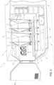
- the cab 1 comprises at least one collapsible anti-mine seat 10 carried by the cab 1 so as to assume a first configuration, closed ( Figure 1 ), wherein it is housed, compacted, at one of the walls 2 of the cab 1 above the sick carriage system 5 and a second configuration, open ( Figure 2 ), wherein it is mounted between the walls 2 of the cab 2 and available for use.
- the collapsible anti-mine seat 10 in the first configuration is housed in a container 11 fixed to one of the side walls 2', above the sick carriage system 5.
- the container 11 can be a fabric bag attachable to the wall 2 by means of a removable coupling such as Velcro or buttons or straps.
- collapsible anti-mine seat 10 is specifically illustrated according to the invention.
- the collapsible anti-mine seat 10 comprises a plurality of anchorage points 12, advantageously four upper anchorage points and four lower anchorage points.
- Each anchorage point 12 essentially comprises a hook element 12' configured to cooperate with a seat 13, such as an eyebolt, rigidly carried by the cab 1.
- the collapsible anti-mine seat 10 comprises a plurality of portions 16, 17, 18 made of flexible (i.e. not rigid) anti-mine material which are connected by straps to the upper and lower anchorage points for defining a seating space 15, as is specifically described in the following.
- portions 16, 17, 18 made of flexible (i.e. not rigid) anti-mine material which are connected by straps to the upper and lower anchorage points for defining a seating space 15, as is specifically described in the following.
- the type of anti-mine material will not be described, as it is known and variable per se depending on the type of protection required.
- the aforementioned plurality of portions 16, 17, 18 comprises:
- the collapsible anti-mine seat 10 comprises a plurality of straps adapted to connect the aforementioned portions to one or more of the anchorage points 12.
- collapsible anti-mine seat 10 which advantageously has a symmetric shape with respect to a sagittal surface thereof, comprises:
- the collapsible anti-mine seat 10 also comprises various support and hinge elements for favouring the attachment of the aforementioned series of straps 21, 22, 23, 24.
- the collapsible anti-mine seat 10 comprises:
- the seats 13 which allow the attachment of the anchorage points 12 to the cab 1 are advantageously made on the roof 2′′′ for the upper anchorage points 12 and on the side wall 2' or on the floor 2" for the lower anchorage points 12.
- the lower anchorage points 12 are fixed to the side wall 12 or to the guides 16 or to the support surface 4', whereas the front lower anchorage points 12 are fixed to the vertical wall 4" or to the floor 2".
- the cab 1 is equipped for the carriage of sick people. Therefore, a sick person can be carried by means of the sick carriage device 5 supported by the platform 4.
- the collapsible anti-mine seat 10 is placed closed inside the container 11 and thus does not occupy space.
- the cab 1 is equipped for the deposit of passengers in a sitting position.
- the collapsible anti-mine seat 10 is open and fixed at the ends thereof between the roof 2′′′ and the floor 2" of the cab, where the seating portion 17 is above the platform 4, so that it can be utilized as a seat for the passenger.
- the passage between the first and the second configuration is enabled by opening the container 11 and unfolding the collapsible anti-mine seat 10 which is fixed by means of the anchorage points 12, whereas between the second and the first configuration, it takes place by compacting the seat and reclosing it in the container 11 after freeing the anchorage points 12.
- the vehicular seat according to the invention it is possible to reconfigure a military or emergency vehicle in a quick manner.
- the vehicular cab can pass from a configuration for the carriage of sick people/goods to a configuration for the carriage of people by simply mounting the collapsible anti-mine seat above the sick carriage device.
- the container provided enables restraining the seat in a compact mode inside a predefined space preventing increasing the bulks in the space 3.
- the possibility to remove the litter device enables obtaining a wide seating space once the collapsible anti-mine seat is mounted.
- collapsible anti-mine seat provides a strong configuration of the collapsible anti-mine seat in the mounted configuration but also compact when closed inside the container.
- the type of sick carriage device or the shape of the collapsible anti-mine seat, and the components comprised by it, can vary.
- collapsible anti-mine devices can vary, as well as the arrangement thereof with respect to the walls of the cab.
Landscapes
- Engineering & Computer Science (AREA)
- Health & Medical Sciences (AREA)
- Public Health (AREA)
- Transportation (AREA)
- Mechanical Engineering (AREA)
- Animal Behavior & Ethology (AREA)
- Life Sciences & Earth Sciences (AREA)
- Aviation & Aerospace Engineering (AREA)
- General Health & Medical Sciences (AREA)
- Veterinary Medicine (AREA)
- Biomedical Technology (AREA)
- Nursing (AREA)
- General Engineering & Computer Science (AREA)
- Body Structure For Vehicles (AREA)
Abstract
Description
- This patent application claims priority from
Italian patent application no. 102022000011804 filed on June 03, 2022 - The present invention relates to a vehicular cab, in particular to a vehicular cab comprising an improved anti-mine seat and an improved anti-mine seat.
- The present invention is preferably, although not exclusively, applied to a military vehicle. Reference will be made to such application in the following by way of example.
- Some types of vehicles, such as military vehicles or emergency vehicles in war zones, can be provided with anti-mine seats.
- Such seats are made of multilayer materials configured to prevent the transmission of impacts and accelerations due to explosions, such as explosions of mines.
- However, military or emergency vehicles in a war zone can also be used for the carriage of material or wounded/sick people who need to be placed lying.
- Therefore, military or emergency vehicles in a war zone comprise cabs configured in a material or sick/wounded people carriage mode, i.e. provided with litters or stretchers or, alternatively, in a passenger carriage mode, i.e. provided with anti-mine seats.
- It is therefore evident that the reconfiguration of a vehicle between the two aforementioned configurations requires time and is thus a difficult operation, thus not suitable for emergency or war situations.
- Therefore, the need is felt to provide a vehicular cab for a military or emergency vehicle in a war zone provided with anti-mine seats which can enable the reconfiguration in a quick and facilitated manner.
- The object of the present invention is to satisfy the above-described needs in an optimized and cost-effective manner.
- The aforementioned object is achieved by a vehicular cab and a vehicle as claimed in the appended claims.
- In order to better understand the present invention, a preferred embodiment is described in the following, by way of non-limiting example and with reference to the accompanying drawings, wherein:
-
Figure 1 is a simplified perspective view, with parts removed for clarity, of a vehicular cab according to the invention in a first operating condition; -
Figure 2 is a simplified perspective view, with parts removed for clarity, of a vehicular cab according to the invention in a second operating condition; and -
Figure 3 is a simplified perspective view, with parts removed for clarity, of an anti-mine seat being part of a vehicular cab according to the invention. - In the accompanying figures, a cab 1 is illustrated for a vehicle (not completely illustrated) of military or emergency type in a war zone. The following description will refer to a cab provided with a sick carriage system and to a particular arrangement of the described seats. However, it is evident that the described vehicle can be used for various military or emergency purposes, and the seats could be placed in the cab in different positions.
- The cab 1 comprises a plurality of
walls 2 defining aninner space 3 extending along a longitudinal axis A of the cab 1 and adapted to be occupied by the passengers of the vehicle, as is described in the following. In particular, the cab 1 comprises a pair of side walls 2', afloor 2" and aroof 2‴ delimiting theinner space 3. - At the front, the cab 1 can be closed or open, i.e. it continues with a driving position of the vehicle, whereas at the back it comprises at least one
hatch 2a configured to selectively allow the access to thespace 3. - In particular, the cab 1 can be provided with a
platform 4 defining a raised surface with respect to thefloor 2". In particular, theplatform 4 is made stepped and thus defines a raised support surface 4' parallel to thefloor 2" and avertical surface 4" joining the support surface 4' to the floor 2'. - The cab 1 advantageously comprises a
sick carriage system 5 preferably carried by theplatform 4 and configured to house a person in a lying position on the support surface 4' . Consequently, theplatform 4 has a length along the longitudinal axis A of the cab 1 such to enable housing a person, therefore of at least 2 mt. - The
sick carriage system 5 advantageously comprises at least oneguide 6, in the described case a pair ofguides 6, carried, preferably in a fixed manner, by theplatform 4. In particular, theguides 6 are fixed to the support surface 4' and extend vertically from it. - The
sick carriage system 5 further comprises a litter device 7 such as a stretcher, a litter, a spoon or other devices adapted for the carriage of sick people. The litter device 7 is configured to be supported by theguides 6 and preferably connected to them. In particular, it can be connected by means of a sliding connection or other types of movable and removable connections. - Specifically, the
sick carriage system 5 is configured to assume a first configuration, wherein the litter device 7 is fixed to theguides 6 for the carriage of a sick person in thespace 3, and a second configuration, wherein it is removed from theguides 6 for allowing the handling of the sick person with respect to thespace 3. - The cab 1, i.e. the walls 2', the
hatch 2a or theplatform 4 can be further provided with spaces for housing objects useful for the vehicle or attachment devices for the aforementioned objects, not further described for the sake of brevity. - In particular, the cab 1 comprises at least one collapsible
anti-mine seat 10 carried by the cab 1 so as to assume a first configuration, closed (Figure 1 ), wherein it is housed, compacted, at one of thewalls 2 of the cab 1 above thesick carriage system 5 and a second configuration, open (Figure 2 ), wherein it is mounted between thewalls 2 of thecab 2 and available for use. - In particular, the collapsible
anti-mine seat 10 in the first configuration is housed in acontainer 11 fixed to one of the side walls 2', above thesick carriage system 5. - Specifically, the
container 11 can be a fabric bag attachable to thewall 2 by means of a removable coupling such as Velcro or buttons or straps. - With reference to
Figure 3 , the collapsibleanti-mine seat 10 is specifically illustrated according to the invention. - The collapsible
anti-mine seat 10 comprises a plurality ofanchorage points 12, advantageously four upper anchorage points and four lower anchorage points. - Each
anchorage point 12 essentially comprises ahook element 12' configured to cooperate with aseat 13, such as an eyebolt, rigidly carried by the cab 1. - The collapsible
anti-mine seat 10 comprises a plurality ofportions seating space 15, as is specifically described in the following. For the sake of brevity, the type of anti-mine material will not be described, as it is known and variable per se depending on the type of protection required. - In particular, in the exemplifying embodiment described, the aforementioned plurality of
portions - An
intermediate portion 16 comprising a rear wall 16' with a backrest function connected along side edges, at least along part of their length, to a pair ofside walls 16" with side restraint functions; - A
lower portion 17 composed of a single seat wall; and - An
upper portion 18 headrest comprising a rear wall 18' connected along side edges, at least along part of their length and in the particular case along their entire length, to a pair ofside walls 18" with side restraint functions. - More specifically:
- the
side portions 16", 18" advantageously have a triangular shape; - the central portion 18' of the
upper portion 18 has a quadrangular shape, just like thelower portion 17; - the central portion 16' of the
upper portion 16 has a trapezoidal shape. - As aforementioned, the collapsible
anti-mine seat 10 comprises a plurality of straps adapted to connect the aforementioned portions to one or more of theanchorage points 12. - According to the above-described embodiment, with reference to only one side of the collapsible
anti-mine seat 10 which advantageously has a symmetric shape with respect to a sagittal surface thereof, comprises: - a first series of
straps 21 connecting theupper portion 16 and theintermediate portion 18 to the plurality ofupper anchorage points 12. In particular, such first series ofstraps 21 comprises afirst strap 21a connecting a portion of the joining edge between theupper portion 16 and theintermediate portion 18 directly to the upper andrear anchorage points 12, asecond strap 21b connecting thefirst strap 21a with an end edge joining the main portion and theside portions 16', 16" of theupper portion 16 and athird strap 21c connecting an upper edge of theside portions 16" with a further series of straps, as is described in the following; - a second series of
straps 22 comprising a first and asecond strap side portions 16" of theintermediate portion 16 and configured to connect an edge of the central portion 16' to a support element described in the following; - a third series of
straps 23 comprising a forkedstrap 23, fixed at an end to one of the frontupper anchorage points 12 and forked on the other end for being fixed to the element to which the second series ofstraps 22 connects and to a further support element described in the following. - a fourth series of
straps 24 comprising afirst strap 24a connecting the support element connected to the second series ofstraps 22 with a frontlower anchorage point 12 and asecond strap 24b connecting the aforementioned frontlower anchorage point 12 with a rearlower anchorage point 12 passing through a further support element described in the following. - As aforementioned, the collapsible
anti-mine seat 10 also comprises various support and hinge elements for favouring the attachment of the aforementioned series ofstraps - In particular, in the described embodiment, the collapsible
anti-mine seat 10 comprises: - A first, a second, a third and a
fourth support elements 25, made as tubular elements, parallel to each other, arranged respectively in a lower edge of the central portion 16' of theintermediate portion 16, in the front and rear edges of theseating portion 17 and below the seatingportion 17, in the proximity of the front lower anchorage points 12 as footrest. - A first and a
second hinge 26 configured to allow the support for the fourth plurality ofstraps 24, in particular to allow a point of referral with respect to the anchorage points 12. - Consequently to what described above, the
seats 13 which allow the attachment of the anchorage points 12 to the cab 1 are advantageously made on theroof 2‴ for the upper anchorage points 12 and on the side wall 2' or on thefloor 2" for the lower anchorage points 12. In particular, the lower anchorage points 12 are fixed to theside wall 12 or to theguides 16 or to the support surface 4', whereas the front lower anchorage points 12 are fixed to thevertical wall 4" or to thefloor 2". - The operation of the embodiment of the above-described cab 1 is as follows.
- In a first vehicular configuration, the cab 1 is equipped for the carriage of sick people. Therefore, a sick person can be carried by means of the
sick carriage device 5 supported by theplatform 4. In such configuration, the collapsibleanti-mine seat 10 is placed closed inside thecontainer 11 and thus does not occupy space. - In a second configuration, the cab 1 is equipped for the deposit of passengers in a sitting position. In such configuration, the collapsible
anti-mine seat 10 is open and fixed at the ends thereof between theroof 2‴ and thefloor 2" of the cab, where theseating portion 17 is above theplatform 4, so that it can be utilized as a seat for the passenger. - In particular, the passage between the first and the second configuration is enabled by opening the
container 11 and unfolding the collapsibleanti-mine seat 10 which is fixed by means of the anchorage points 12, whereas between the second and the first configuration, it takes place by compacting the seat and reclosing it in thecontainer 11 after freeing the anchorage points 12. - Based on the foregoing, the advantages of a vehicular cab and a seat according to the invention are evident.
- Thanks to the vehicular seat according to the invention, it is possible to reconfigure a military or emergency vehicle in a quick manner.
- In particular, the vehicular cab can pass from a configuration for the carriage of sick people/goods to a configuration for the carriage of people by simply mounting the collapsible anti-mine seat above the sick carriage device.
- The container provided enables restraining the seat in a compact mode inside a predefined space preventing increasing the bulks in the
space 3. - The possibility to remove the litter device enables obtaining a wide seating space once the collapsible anti-mine seat is mounted.
- Furthermore, the particular arrangement of portions, straps and other elements of the collapsible anti-mine seat provide a strong configuration of the collapsible anti-mine seat in the mounted configuration but also compact when closed inside the container.
- Finally, it is clear that modifications and variations can be made to the seat and to the vehicular cab according to the present invention which however do not depart from the scope of protection defined by the claims.
- For example, the type of sick carriage device or the shape of the collapsible anti-mine seat, and the components comprised by it, can vary.
- Similarly, the number of collapsible anti-mine devices can vary, as well as the arrangement thereof with respect to the walls of the cab.
Claims (16)
- Vehicular cab (1) comprising a plurality of walls (2) defining a space (3) extending along a longitudinal axis (A), said walls (2) comprising a pair of side walls (2'), a floor (2") and a roof (2‴), said cab (1) comprising a collapsible anti-mine seat (10), and a container (11) fixed to one of said side walls (2') and/or said roof (2‴), said collapsible anti-mine seat (10) being configured to assume a first configuration, closed, wherein it is housed in said container (11) so as to leave free the space below it, and a second configuration, open, wherein it is mounted between said side walls (2') and/or said roof (2‴) and/or said floor (2") so as to define a seating space (15) above said floor (2").
- Cab as claimed in claim 1, wherein said collapsible anti-mine seat (10) comprises a plurality of upper and lower anchorage points (12) and a plurality of portions (16, 17, 18) made of anti-mine material connected to one another and to said anchorage points (12), said anchorage points (12) being configured to allow the connection of said collapsible anti-mine seat (10) to one of said side walls (2') and/or said roof (2‴), above, and to one of said side walls (2') and/or said floor (2"), below, in said second configuration.
- Cab as claimed in claim 2, wherein said anchorage points (12) comprise a hook element (12') integral with said portions (16, 17, 18) configured to cooperate with a seat (13) integral with said cab (1).
- Cab as claimed in claim 3, wherein said seat (13) is defined by an eyebolt fixed to one of said walls (2).
- Cab as claimed in any of the preceding claims, wherein said cab (1) comprises a platform (4) raised with respect to said floor (2") and defining a support surface (4'), said cab (1) comprising a sick carriage system (5) carried by said support surface (4'), said collapsible anti-mine seat (10) being placed above said sick carriage system (5) .
- Cab as claimed in claim 5, wherein said sick carriage system (5) comprises at least one guide element (6) rigidly carried by said platform (4) and a litter device (7) configured to cooperate with said guide element (6) in a selectively movable and removable manner.
- Cab as claimed in claim 6, wherein said litter device (7) is rigidly carried by said guide element (6) in said first configuration and wherein said litter device (7) is removed from said guide element (6) in said second configuration.
- Cab as claimed in any of the preceding claims, wherein said container (11) is a bag.
- Cab as claimed in any of the preceding claims, wherein said collapsible anti-mine seat (10) comprises a plurality of upper and lower anchorage points (12) and a plurality of portions (16, 17, 18) made of flexible anti-mine material connected to one another and to said anchorage points (12), said anchorage points (12) being configured to allow the connection of said collapsible anti-mine seat (10) to one of the walls (2) of said vehicle, said collapsible anti-mine seat (10) comprising at least one plurality of straps (21, 22, 23, 24) connecting said portions (16, 17, 18) to one another and to said anchorage points (12).
- Cab as claimed in claim 9, wherein said collapsible anti-mine seat (10) comprises support elements (25) and/or hinge elements (26) configured to support the attachment of said at least one plurality of straps (21, 22, 23, 24) between said portions (16, 17, 18).
- Cab as claimed in claim 10, wherein said support elements (25) comprise tubular elements.
- Cab as claimed in claim 11, wherein said tubular elements, in use, are parallel to each other.
- Cab as claimed in claim 10 to 12, wherein said hinge elements (26) are configured to provide a point of referral of said at least one plurality of straps (21, 22, 23, 24) between said anchorage points (12).
- Cab as claimed in any of claims 9 to 13, wherein said collapsible anti-mine seat (10) comprises:• An intermediate portion (16) comprising a rear wall (16') with a backrest function connected along side edges, at least along part of their length, to a pair of side walls (16") with side restraint functions;• A lower portion (17) comprising a single seat wall; and• An upper portion (18) headrest comprising a rear wall (18') connected along side edges, at least along part of their length, to a pair of side walls (18") with lateral restraint functions.
- Cab as claimed in claim 14, wherein:• said side walls (16", 18") have a triangular shape;• said rear wall (18') of the upper portion (18) and said lower portion (17) have a quadrangular shape; and• said rear wall (16') of the intermediate portion (16) has a trapezoidal shape.
- Military or emergency type vehicle comprising a vehicular cab as claimed in any of the preceding claims.
Applications Claiming Priority (1)
| Application Number | Priority Date | Filing Date | Title |
|---|---|---|---|
| IT102022000011804A IT202200011804A1 (en) | 2022-06-03 | 2022-06-03 | VEHICLE CABIN EQUIPPED WITH AN IMPROVED MINE-PROOF SEAT AND IMPROVED MINE-PROOF SEAT |
Publications (1)
| Publication Number | Publication Date |
|---|---|
| EP4286218A1 true EP4286218A1 (en) | 2023-12-06 |
Family
ID=83081166
Family Applications (1)
| Application Number | Title | Priority Date | Filing Date |
|---|---|---|---|
| EP23176700.5A Pending EP4286218A1 (en) | 2022-06-03 | 2023-06-01 | Vehicular cab provided with an improved anti-mine seat |
Country Status (2)
| Country | Link |
|---|---|
| EP (1) | EP4286218A1 (en) |
| IT (1) | IT202200011804A1 (en) |
Citations (4)
| Publication number | Priority date | Publication date | Assignee | Title |
|---|---|---|---|---|
| US3868143A (en) * | 1973-04-25 | 1975-02-25 | Us Navy | Crash load attenuating troop seat |
| DE4303719A1 (en) * | 1993-02-09 | 1994-08-11 | Autoflug Gmbh | Textile safety seat |
| DE102004009557B3 (en) * | 2004-02-25 | 2005-04-21 | Autoflug Gmbh | Flexible support on land, sea or air vehicle for goods pallet or seat for personnel has network of belts or straps with spring attachments and pallet or seat mountings |
| WO2008019389A2 (en) * | 2006-08-10 | 2008-02-14 | Pierce Manufacturing, Inc. | Ambulance seating system |
-
2022
- 2022-06-03 IT IT102022000011804A patent/IT202200011804A1/en unknown
-
2023
- 2023-06-01 EP EP23176700.5A patent/EP4286218A1/en active Pending
Patent Citations (4)
| Publication number | Priority date | Publication date | Assignee | Title |
|---|---|---|---|---|
| US3868143A (en) * | 1973-04-25 | 1975-02-25 | Us Navy | Crash load attenuating troop seat |
| DE4303719A1 (en) * | 1993-02-09 | 1994-08-11 | Autoflug Gmbh | Textile safety seat |
| DE102004009557B3 (en) * | 2004-02-25 | 2005-04-21 | Autoflug Gmbh | Flexible support on land, sea or air vehicle for goods pallet or seat for personnel has network of belts or straps with spring attachments and pallet or seat mountings |
| WO2008019389A2 (en) * | 2006-08-10 | 2008-02-14 | Pierce Manufacturing, Inc. | Ambulance seating system |
Also Published As
| Publication number | Publication date |
|---|---|
| IT202200011804A1 (en) | 2023-12-03 |
Similar Documents
| Publication | Publication Date | Title |
|---|---|---|
| US10772288B1 (en) | Pet carrier car seat | |
| US5186587A (en) | Automotive barrier net | |
| US20060273566A1 (en) | Military motor vehicle for transporting personnel | |
| ITRM990528A1 (en) | REAR SEAT STRUCTURE FOR VEHICLE. | |
| US20200307489A1 (en) | Seat assembly with full seatback airbag | |
| JP6856150B1 (en) | Vehicle occupant restraint structure | |
| EP4286218A1 (en) | Vehicular cab provided with an improved anti-mine seat | |
| EP2238959A1 (en) | Wheelchair anchoring system | |
| EP0148596A1 (en) | Road vehicles | |
| EP0969990B1 (en) | Reinforcement means for vehicle | |
| US11273791B1 (en) | Seat belt structure for a vehicle | |
| EP1099595A2 (en) | Folding seat | |
| RU168582U1 (en) | Mobile car seat | |
| US10894490B2 (en) | Foldable restraint releasably attached to a main support structure of a vehicle | |
| SE1050336A1 (en) | Combined bed and storage space for vehicles | |
| CN121443142A (en) | Foldable platforms in vehicles | |
| US9126553B2 (en) | Bunk restraint system | |
| GB2293318A (en) | vehicle seat assembly with safety beam | |
| EP4286217A1 (en) | Improved anti-mine seat | |
| US10220789B2 (en) | Baggage restraint system | |
| JPH06107124A (en) | Vehicle seat belt arrangement structure | |
| KR100520768B1 (en) | Apparatus for reinforcing frame of rear seat for automobile | |
| CN106536289B (en) | Motor vehicle comprising a four-person seat | |
| JP7525034B1 (en) | vehicle | |
| DE102019009193B4 (en) | Vehicle Safety V Harness System |
Legal Events
| Date | Code | Title | Description |
|---|---|---|---|
| PUAI | Public reference made under article 153(3) epc to a published international application that has entered the european phase |
Free format text: ORIGINAL CODE: 0009012 |
|
| STAA | Information on the status of an ep patent application or granted ep patent |
Free format text: STATUS: THE APPLICATION HAS BEEN PUBLISHED |
|
| AK | Designated contracting states |
Kind code of ref document: A1 Designated state(s): AL AT BE BG CH CY CZ DE DK EE ES FI FR GB GR HR HU IE IS IT LI LT LU LV MC ME MK MT NL NO PL PT RO RS SE SI SK SM TR |
|
| STAA | Information on the status of an ep patent application or granted ep patent |
Free format text: STATUS: REQUEST FOR EXAMINATION WAS MADE |
|
| 17P | Request for examination filed |
Effective date: 20240606 |
|
| RBV | Designated contracting states (corrected) |
Designated state(s): AL AT BE BG CH CY CZ DE DK EE ES FI FR GB GR HR HU IE IS IT LI LT LU LV MC ME MK MT NL NO PL PT RO RS SE SI SK SM TR |
|
| STAA | Information on the status of an ep patent application or granted ep patent |
Free format text: STATUS: EXAMINATION IS IN PROGRESS |
|
| 17Q | First examination report despatched |
Effective date: 20250528 |
|
| RAP3 | Party data changed (applicant data changed or rights of an application transferred) |
Owner name: IDV DEFENCE VEHICLES ITALIA S.P.A. |