EP4286205A1 - Electrified vehicle - Google Patents
Electrified vehicle Download PDFInfo
- Publication number
- EP4286205A1 EP4286205A1 EP23167763.4A EP23167763A EP4286205A1 EP 4286205 A1 EP4286205 A1 EP 4286205A1 EP 23167763 A EP23167763 A EP 23167763A EP 4286205 A1 EP4286205 A1 EP 4286205A1
- Authority
- EP
- European Patent Office
- Prior art keywords
- power
- converter
- voltage
- relays
- storage device
- Prior art date
- Legal status (The legal status is an assumption and is not a legal conclusion. Google has not performed a legal analysis and makes no representation as to the accuracy of the status listed.)
- Pending
Links
- 238000000034 method Methods 0.000 claims description 124
- 230000008569 process Effects 0.000 claims description 124
- 230000002457 bidirectional effect Effects 0.000 claims description 109
- 230000005856 abnormality Effects 0.000 claims description 15
- 238000012937 correction Methods 0.000 claims description 12
- 238000001514 detection method Methods 0.000 claims description 10
- 230000003213 activating effect Effects 0.000 claims description 8
- 238000012546 transfer Methods 0.000 claims description 4
- 230000004913 activation Effects 0.000 description 16
- 230000007257 malfunction Effects 0.000 description 13
- 230000004048 modification Effects 0.000 description 13
- 238000012986 modification Methods 0.000 description 13
- 238000002955 isolation Methods 0.000 description 9
- 238000010586 diagram Methods 0.000 description 8
- 238000003745 diagnosis Methods 0.000 description 6
- 238000002474 experimental method Methods 0.000 description 6
- 230000007423 decrease Effects 0.000 description 5
- 230000006870 function Effects 0.000 description 5
- 239000003990 capacitor Substances 0.000 description 4
- 238000006243 chemical reaction Methods 0.000 description 3
- 230000000694 effects Effects 0.000 description 2
- 238000009499 grossing Methods 0.000 description 2
- HBBGRARXTFLTSG-UHFFFAOYSA-N Lithium ion Chemical compound [Li+] HBBGRARXTFLTSG-UHFFFAOYSA-N 0.000 description 1
- 239000011244 liquid electrolyte Substances 0.000 description 1
- 229910001416 lithium ion Inorganic materials 0.000 description 1
- 229910052987 metal hydride Inorganic materials 0.000 description 1
- 229910052759 nickel Inorganic materials 0.000 description 1
- PXHVJJICTQNCMI-UHFFFAOYSA-N nickel Substances [Ni] PXHVJJICTQNCMI-UHFFFAOYSA-N 0.000 description 1
- -1 nickel metal hydride Chemical class 0.000 description 1
- 238000012545 processing Methods 0.000 description 1
- 230000004044 response Effects 0.000 description 1
- 239000007784 solid electrolyte Substances 0.000 description 1
- 230000001360 synchronised effect Effects 0.000 description 1
Images


Classifications
-
- B—PERFORMING OPERATIONS; TRANSPORTING
- B60—VEHICLES IN GENERAL
- B60L—PROPULSION OF ELECTRICALLY-PROPELLED VEHICLES; SUPPLYING ELECTRIC POWER FOR AUXILIARY EQUIPMENT OF ELECTRICALLY-PROPELLED VEHICLES; ELECTRODYNAMIC BRAKE SYSTEMS FOR VEHICLES IN GENERAL; MAGNETIC SUSPENSION OR LEVITATION FOR VEHICLES; MONITORING OPERATING VARIABLES OF ELECTRICALLY-PROPELLED VEHICLES; ELECTRIC SAFETY DEVICES FOR ELECTRICALLY-PROPELLED VEHICLES
- B60L3/00—Electric devices on electrically-propelled vehicles for safety purposes; Monitoring operating variables, e.g. speed, deceleration or energy consumption
- B60L3/0023—Detecting, eliminating, remedying or compensating for drive train abnormalities, e.g. failures within the drive train
- B60L3/0069—Detecting, eliminating, remedying or compensating for drive train abnormalities, e.g. failures within the drive train relating to the isolation, e.g. ground fault or leak current
-
- B—PERFORMING OPERATIONS; TRANSPORTING
- B60—VEHICLES IN GENERAL
- B60L—PROPULSION OF ELECTRICALLY-PROPELLED VEHICLES; SUPPLYING ELECTRIC POWER FOR AUXILIARY EQUIPMENT OF ELECTRICALLY-PROPELLED VEHICLES; ELECTRODYNAMIC BRAKE SYSTEMS FOR VEHICLES IN GENERAL; MAGNETIC SUSPENSION OR LEVITATION FOR VEHICLES; MONITORING OPERATING VARIABLES OF ELECTRICALLY-PROPELLED VEHICLES; ELECTRIC SAFETY DEVICES FOR ELECTRICALLY-PROPELLED VEHICLES
- B60L3/00—Electric devices on electrically-propelled vehicles for safety purposes; Monitoring operating variables, e.g. speed, deceleration or energy consumption
- B60L3/0023—Detecting, eliminating, remedying or compensating for drive train abnormalities, e.g. failures within the drive train
- B60L3/0084—Detecting, eliminating, remedying or compensating for drive train abnormalities, e.g. failures within the drive train relating to control modules
-
- B—PERFORMING OPERATIONS; TRANSPORTING
- B60—VEHICLES IN GENERAL
- B60L—PROPULSION OF ELECTRICALLY-PROPELLED VEHICLES; SUPPLYING ELECTRIC POWER FOR AUXILIARY EQUIPMENT OF ELECTRICALLY-PROPELLED VEHICLES; ELECTRODYNAMIC BRAKE SYSTEMS FOR VEHICLES IN GENERAL; MAGNETIC SUSPENSION OR LEVITATION FOR VEHICLES; MONITORING OPERATING VARIABLES OF ELECTRICALLY-PROPELLED VEHICLES; ELECTRIC SAFETY DEVICES FOR ELECTRICALLY-PROPELLED VEHICLES
- B60L3/00—Electric devices on electrically-propelled vehicles for safety purposes; Monitoring operating variables, e.g. speed, deceleration or energy consumption
- B60L3/0023—Detecting, eliminating, remedying or compensating for drive train abnormalities, e.g. failures within the drive train
- B60L3/003—Detecting, eliminating, remedying or compensating for drive train abnormalities, e.g. failures within the drive train relating to inverters
-
- B—PERFORMING OPERATIONS; TRANSPORTING
- B60—VEHICLES IN GENERAL
- B60L—PROPULSION OF ELECTRICALLY-PROPELLED VEHICLES; SUPPLYING ELECTRIC POWER FOR AUXILIARY EQUIPMENT OF ELECTRICALLY-PROPELLED VEHICLES; ELECTRODYNAMIC BRAKE SYSTEMS FOR VEHICLES IN GENERAL; MAGNETIC SUSPENSION OR LEVITATION FOR VEHICLES; MONITORING OPERATING VARIABLES OF ELECTRICALLY-PROPELLED VEHICLES; ELECTRIC SAFETY DEVICES FOR ELECTRICALLY-PROPELLED VEHICLES
- B60L3/00—Electric devices on electrically-propelled vehicles for safety purposes; Monitoring operating variables, e.g. speed, deceleration or energy consumption
- B60L3/0023—Detecting, eliminating, remedying or compensating for drive train abnormalities, e.g. failures within the drive train
- B60L3/0038—Detecting, eliminating, remedying or compensating for drive train abnormalities, e.g. failures within the drive train relating to sensors
-
- B—PERFORMING OPERATIONS; TRANSPORTING
- B60—VEHICLES IN GENERAL
- B60L—PROPULSION OF ELECTRICALLY-PROPELLED VEHICLES; SUPPLYING ELECTRIC POWER FOR AUXILIARY EQUIPMENT OF ELECTRICALLY-PROPELLED VEHICLES; ELECTRODYNAMIC BRAKE SYSTEMS FOR VEHICLES IN GENERAL; MAGNETIC SUSPENSION OR LEVITATION FOR VEHICLES; MONITORING OPERATING VARIABLES OF ELECTRICALLY-PROPELLED VEHICLES; ELECTRIC SAFETY DEVICES FOR ELECTRICALLY-PROPELLED VEHICLES
- B60L53/00—Methods of charging batteries, specially adapted for electric vehicles; Charging stations or on-board charging equipment therefor; Exchange of energy storage elements in electric vehicles
- B60L53/20—Methods of charging batteries, specially adapted for electric vehicles; Charging stations or on-board charging equipment therefor; Exchange of energy storage elements in electric vehicles characterised by converters located in the vehicle
- B60L53/22—Constructional details or arrangements of charging converters specially adapted for charging electric vehicles
-
- B—PERFORMING OPERATIONS; TRANSPORTING
- B60—VEHICLES IN GENERAL
- B60L—PROPULSION OF ELECTRICALLY-PROPELLED VEHICLES; SUPPLYING ELECTRIC POWER FOR AUXILIARY EQUIPMENT OF ELECTRICALLY-PROPELLED VEHICLES; ELECTRODYNAMIC BRAKE SYSTEMS FOR VEHICLES IN GENERAL; MAGNETIC SUSPENSION OR LEVITATION FOR VEHICLES; MONITORING OPERATING VARIABLES OF ELECTRICALLY-PROPELLED VEHICLES; ELECTRIC SAFETY DEVICES FOR ELECTRICALLY-PROPELLED VEHICLES
- B60L58/00—Methods or circuit arrangements for monitoring or controlling batteries or fuel cells, specially adapted for electric vehicles
- B60L58/10—Methods or circuit arrangements for monitoring or controlling batteries or fuel cells, specially adapted for electric vehicles for monitoring or controlling batteries
- B60L58/18—Methods or circuit arrangements for monitoring or controlling batteries or fuel cells, specially adapted for electric vehicles for monitoring or controlling batteries of two or more battery modules
- B60L58/20—Methods or circuit arrangements for monitoring or controlling batteries or fuel cells, specially adapted for electric vehicles for monitoring or controlling batteries of two or more battery modules having different nominal voltages
-
- B—PERFORMING OPERATIONS; TRANSPORTING
- B60—VEHICLES IN GENERAL
- B60L—PROPULSION OF ELECTRICALLY-PROPELLED VEHICLES; SUPPLYING ELECTRIC POWER FOR AUXILIARY EQUIPMENT OF ELECTRICALLY-PROPELLED VEHICLES; ELECTRODYNAMIC BRAKE SYSTEMS FOR VEHICLES IN GENERAL; MAGNETIC SUSPENSION OR LEVITATION FOR VEHICLES; MONITORING OPERATING VARIABLES OF ELECTRICALLY-PROPELLED VEHICLES; ELECTRIC SAFETY DEVICES FOR ELECTRICALLY-PROPELLED VEHICLES
- B60L2210/00—Converter types
- B60L2210/10—DC to DC converters
-
- B—PERFORMING OPERATIONS; TRANSPORTING
- B60—VEHICLES IN GENERAL
- B60L—PROPULSION OF ELECTRICALLY-PROPELLED VEHICLES; SUPPLYING ELECTRIC POWER FOR AUXILIARY EQUIPMENT OF ELECTRICALLY-PROPELLED VEHICLES; ELECTRODYNAMIC BRAKE SYSTEMS FOR VEHICLES IN GENERAL; MAGNETIC SUSPENSION OR LEVITATION FOR VEHICLES; MONITORING OPERATING VARIABLES OF ELECTRICALLY-PROPELLED VEHICLES; ELECTRIC SAFETY DEVICES FOR ELECTRICALLY-PROPELLED VEHICLES
- B60L2240/00—Control parameters of input or output; Target parameters
- B60L2240/40—Drive Train control parameters
- B60L2240/52—Drive Train control parameters related to converters
- B60L2240/527—Voltage
-
- B—PERFORMING OPERATIONS; TRANSPORTING
- B60—VEHICLES IN GENERAL
- B60L—PROPULSION OF ELECTRICALLY-PROPELLED VEHICLES; SUPPLYING ELECTRIC POWER FOR AUXILIARY EQUIPMENT OF ELECTRICALLY-PROPELLED VEHICLES; ELECTRODYNAMIC BRAKE SYSTEMS FOR VEHICLES IN GENERAL; MAGNETIC SUSPENSION OR LEVITATION FOR VEHICLES; MONITORING OPERATING VARIABLES OF ELECTRICALLY-PROPELLED VEHICLES; ELECTRIC SAFETY DEVICES FOR ELECTRICALLY-PROPELLED VEHICLES
- B60L2270/00—Problem solutions or means not otherwise provided for
- B60L2270/20—Inrush current reduction, i.e. avoiding high currents when connecting the battery
-
- Y—GENERAL TAGGING OF NEW TECHNOLOGICAL DEVELOPMENTS; GENERAL TAGGING OF CROSS-SECTIONAL TECHNOLOGIES SPANNING OVER SEVERAL SECTIONS OF THE IPC; TECHNICAL SUBJECTS COVERED BY FORMER USPC CROSS-REFERENCE ART COLLECTIONS [XRACs] AND DIGESTS
- Y02—TECHNOLOGIES OR APPLICATIONS FOR MITIGATION OR ADAPTATION AGAINST CLIMATE CHANGE
- Y02T—CLIMATE CHANGE MITIGATION TECHNOLOGIES RELATED TO TRANSPORTATION
- Y02T10/00—Road transport of goods or passengers
- Y02T10/60—Other road transportation technologies with climate change mitigation effect
- Y02T10/70—Energy storage systems for electromobility, e.g. batteries
-
- Y—GENERAL TAGGING OF NEW TECHNOLOGICAL DEVELOPMENTS; GENERAL TAGGING OF CROSS-SECTIONAL TECHNOLOGIES SPANNING OVER SEVERAL SECTIONS OF THE IPC; TECHNICAL SUBJECTS COVERED BY FORMER USPC CROSS-REFERENCE ART COLLECTIONS [XRACs] AND DIGESTS
- Y02—TECHNOLOGIES OR APPLICATIONS FOR MITIGATION OR ADAPTATION AGAINST CLIMATE CHANGE
- Y02T—CLIMATE CHANGE MITIGATION TECHNOLOGIES RELATED TO TRANSPORTATION
- Y02T10/00—Road transport of goods or passengers
- Y02T10/60—Other road transportation technologies with climate change mitigation effect
- Y02T10/7072—Electromobility specific charging systems or methods for batteries, ultracapacitors, supercapacitors or double-layer capacitors
-
- Y—GENERAL TAGGING OF NEW TECHNOLOGICAL DEVELOPMENTS; GENERAL TAGGING OF CROSS-SECTIONAL TECHNOLOGIES SPANNING OVER SEVERAL SECTIONS OF THE IPC; TECHNICAL SUBJECTS COVERED BY FORMER USPC CROSS-REFERENCE ART COLLECTIONS [XRACs] AND DIGESTS
- Y02—TECHNOLOGIES OR APPLICATIONS FOR MITIGATION OR ADAPTATION AGAINST CLIMATE CHANGE
- Y02T—CLIMATE CHANGE MITIGATION TECHNOLOGIES RELATED TO TRANSPORTATION
- Y02T90/00—Enabling technologies or technologies with a potential or indirect contribution to GHG emissions mitigation
- Y02T90/10—Technologies relating to charging of electric vehicles
- Y02T90/14—Plug-in electric vehicles
Definitions
- the present disclosure relates to an electrified vehicle.
- an electrified vehicle described in Japanese Unexamined Patent Application Publication No. 2013-240191 includes a power conversion device that outputs electric power input from an inlet to a power storage device and outputs electric power input from the power storage device to an outlet.
- system main relays SMRs
- PCU power control unit
- the PCU is a drive device that includes an inverter and drives a motor generator by using electric power from the power storage device.
- An object of the present disclosure is to prevent a voltage from being generated in an electric circuit including a drive device due to a leak current in a converter when relays that connect or disconnect a power storage device and the drive device are disconnected.
- An electrified vehicle of the present disclosure includes: a power storage device; an electric motor configured to drive a drive wheel; a drive device configured to drive the electric motor by using electric power in the power storage device; relays configured to connect or disconnect the power storage device and the drive device; a converter connected to power lines between the relays and the drive device and configured to convert alternating current power supplied from an external power supply into direct current power and charge the power storage device; and a control device configured to activate the converter or stop the converter when a voltage is applied to the power lines to which the converter is connected.
- the converter is connected to the power lines between the drive device and the relays that connect or disconnect the power storage device and the drive device.
- the converter converts the alternating current power supplied from the external power supply into the direct current power and charges the power storage device.
- the control device activates the converter when the voltage is applied to the power lines to which the converter is connected. Alternatively, the control device stops the converter when the voltage is applied to the power lines to which the converter is connected.
- An electrified vehicle of the present disclosure includes: a power storage device; an electric motor configured to drive a drive wheel; a drive device configured to drive the electric motor by using electric power in the power storage device; relays configured to connect or disconnect the power storage device and the drive device; a converter connected to power lines between the relays and the drive device and configured to convert direct current power in the power storage device into alternating current power and output the alternating current power to an outlet; and a control device configured to activate the converter or stop the converter when a voltage is applied to the power lines to which the converter is connected.
- the converter is connected to the power lines between the drive device and the relays that connect or disconnect the power storage device and the drive device.
- the converter converts the direct current power in the power storage device into the alternating current power and outputs the alternating current power to the outlet.
- the control device activates the converter when the voltage is applied to the power lines to which the converter is connected. Alternatively, the control device stops the converter when the voltage is applied to the power lines to which the converter is connected.
- An electrified vehicle of the present disclosure includes: a power storage device; an electric motor configured to drive a drive wheel; a drive device configured to drive the electric motor by using electric power in the power storage device; relays configured to connect or disconnect the power storage device and the drive device; a converter connected to power lines between the relays and the drive device and configured to convert alternating current power supplied from an external power supply into direct current power and charge the power storage device and to convert direct current power in the power storage device into alternating current power and output the alternating current power to an outlet; and a control device configured to activate the converter or stop the converter when a voltage is applied to the power lines to which the converter is connected.
- the converter is connected to the power lines between the drive device and the relays that connect or disconnect the power storage device and the drive device.
- the converter is configured to convert the alternating current power supplied from the external power supply into the direct current power and charge the power storage device and to convert the direct current power in the power storage device into the alternating current power and output the alternating current power to the outlet.
- the control device activates the converter when the voltage is applied to the power lines to which the converter is connected. Alternatively, the control device stops the converter when the voltage is applied to the power lines to which the converter is connected.
- the converter is activated when the voltage is applied to the power lines to which the converter is connected (power lines between the relays and the drive device). Even if a leak current is generated from the converter due to the activation of the converter, the voltage is applied to the power lines to which the converter is connected. Therefore, it is possible to suppress an increase in the voltage on the power lines due to the leak current. Therefore, the converter is not activated when the relays that connect or disconnect the power storage device and the drive device are disconnected and no voltage is applied to the power lines. Thus, it is possible to reduce the occurrence of the case where the voltage is generated in the electric circuit including the drive device due to the leak current in the converter.
- the converter is stopped when the voltage is applied to the power lines to which the converter is connected. Therefore, when there is a possibility that a leak current is generated from the converter before the converter is stopped, that is, while the converter is activated, the voltage is applied to the power lines to which the converter is connected. Thus, even if the leak current is generated from the converter, it is possible to suppress the increase in the voltage on the power lines due to the leak current. Further, the converter is stopped when the relays that connect or disconnect the power storage device and the drive device are disconnected and no voltage is applied to the power lines. Thus, it is possible to reduce the occurrence of the case where the voltage is generated in the electric circuit including the drive device due to the leak current in the converter. Therefore, when the relays that connect or disconnect the power storage device and the drive device are disconnected, it is possible to reduce the occurrence of the case where the voltage is generated in the electric circuit including the drive device due to the leak current in the converter.
- the electrified vehicle of the present disclosure may further include: an auxiliary battery configured to supply electric power to an auxiliary device; and a bidirectional direct current-to-direct current converter configured to transfer electric power between the auxiliary battery and the power lines.
- the control device may be configured to execute a connection process for switching each of the relays from a disconnected state to a connected state.
- the connection process may include a process of stepping up the electric power in the auxiliary battery by the bidirectional direct current-to-direct current converter to increase the voltage on the power lines and activating the converter, and a process of switching the relays from the disconnected state to the connected state after the voltage on the power lines has increased to a predetermined value.
- the control device executes the connection process for switching each of the relays from the disconnected state to the connected state.
- the connection process includes the processes of stepping up the electric power in the auxiliary battery by the bidirectional direct current-to-direct current converter to increase the voltage on the power lines and activating the converter, and switching the relays from the disconnected state to the connected state after the voltage on the power lines has increased to the predetermined value.
- the electric power in the auxiliary battery is stepped up by the bidirectional direct current-to-direct current converter to increase the voltage on the power lines and the converter is activated.
- the relays are switched from the disconnected state to the connected state after the voltage on the power lines has increased to the predetermined value.
- the converter is in the stopped state, and the voltage is not generated on the power lines to which the converter is connected due to the leak current from the converter.
- the converter When the converter is not activated, the converter is in an unstable state, and malfunction may occur due to an unintended short circuit, noise, or the like. According to this configuration, the converter is activated when the relays are in the connected state and the voltage of the power storage device is applied to the power lines. Therefore, it is possible to suppress the short circuit or malfunction of the converter when the voltage is applied to the power lines to which the converter is connected (power lines between the relays and the drive device).
- the electrified vehicle of the present disclosure may further include: an auxiliary battery configured to supply electric power to an auxiliary device; and a bidirectional direct current-to-direct current converter configured to transfer electric power between the auxiliary battery and the power lines.
- the control device may be configured to execute a disconnection process for switching each of the relays from a connected state to a disconnected state.
- the disconnection process may include a process of, after the relays have been switched from the connected state to the disconnected state, supplying the electric power on the power lines to the auxiliary battery by the bidirectional direct current-to-direct current converter to step down the voltage on the power lines and stopping the converter.
- the control device executes the disconnection process for switching each of the relays from the connected state to the disconnected state.
- the disconnection process includes the process of, after the relays have been switched from the connected state to the disconnected state, supplying the electric power on the power lines to the auxiliary battery by the bidirectional direct current-to-direct current converter to step down the voltage on the power lines and stopping the converter.
- the electric power on the power lines is supplied to the auxiliary battery by the bidirectional direct current-to-direct current converter to step down the voltage on the power lines and the converter is stopped.
- the converter is in the stopped state, and the voltage is not generated on the power lines to which the converter is connected due to the leak current from the converter. Further, the converter is activated when the relays are in the connected state and the voltage of the power storage device is applied to the power lines. Therefore, it is possible to suppress the short circuit or malfunction of the converter when the voltage is applied to the power lines.
- the relays may include a circuit including a first relay configured to connect or disconnect one pole of the power storage device and the drive device and a limiting resistor connected in series with the first relay, a second relay connected in parallel with the circuit, and a third relay configured to connect or disconnect another pole of the power storage device and the drive device.
- the control device may be configured to execute a connection process for switching each of the relays from a disconnected state to a connected state.
- the connection process may include a process of performing a precharging process for switching the first relay and the third relay from the disconnected state to the connected state and activating the converter, and a process of, after the precharging process has been finished, switching the second relay from the disconnected state to the connected state and switching the first relay to the disconnected state.
- the precharging process is performed to switch the first relay and the third relay from the disconnected state to the connected state.
- the control device activates the converter along with the precharging process. After the precharging process has been finished, the control device switches the second relay from the disconnected state to the connected state and switches the first relay to the disconnected state. Then, the control device terminates the connection process.
- the connection process the voltage on the power lines to which the converter is connected (power lines between the relays and the drive device) is increased by the precharging process, and the converter is activated.
- the second relay is switched from the disconnected state to the connected state and the first relay is switched to the disconnected state. Then, the connection process is terminated.
- the converter is in the stopped state, and the voltage is not generated on the power lines to which the converter is connected due to the leak current from the converter.
- the converter When the converter is not activated, the converter is in an unstable state, and malfunction may occur due to an unintended short circuit, noise, or the like. According to this configuration, the converter is activated when the relays are in the connected state and the voltage of the power storage device is applied to the power lines. Therefore, it is possible to suppress the short circuit or malfunction of the converter when the voltage is applied to the power lines.
- the control device may be configured to execute a disconnection process for switching each of the relays from a connected state to a disconnected state.
- the disconnection process may include a process of switching a relay configured to connect or disconnect one pole of the power storage device and the drive device from the connected state to the disconnected state and, after an elapse of a predetermined period, switching a relay configured to connect or disconnect another pole of the power storage device and the drive device from the connected state to the disconnected state, and a process of stopping the converter within the predetermined period.
- the control device executes the disconnection process for switching each of the relays from the connected state to the disconnected state.
- the relay configured to connect or disconnect one pole of the power storage device and the drive device is switched from the connected state to the disconnected state and, after the elapse of the predetermined period, the relay configured to connect or disconnect another pole of the power storage device and the drive device is switched from the connected state to the disconnected state.
- the converter is stopped within the predetermined period in the disconnection process.
- the converter is activated when the relays are in the connected state and the voltage of the power storage device is applied to the power lines. Therefore, it is possible to suppress the short circuit or malfunction of the converter when the voltage is applied to the power lines.
- control device may be configured to, when all the relays configured to connect or disconnect the power storage device and the drive device are in a disconnected state, execute an abnormality detection process for the drive device or an offset correction process for sensors provided in an electric circuit including the drive device.
- the converter when the relays are in the disconnected state, the converter is in the stopped state and the voltage is not generated on the power lines to which the converter is connected due to the leak current from the converter. Even if the abnormality detection process or the offset correction process is executed under the assumption that no voltage is generated in the electric circuit including the drive device, the erroneous detection or the erroneous correction can be suppressed.
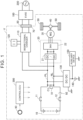
- FIG. 1 is a diagram showing a configuration of an electrified vehicle V according to a first embodiment of the present disclosure.
- the electrified vehicle V includes a battery 10, a power control unit (hereinafter also referred to as "PCU") 20, a motor generator 30, a differential gear 40, and drive wheels 50.
- PCU power control unit
- the battery 10 is a power storage device, and is mounted on the electrified vehicle V as a drive power supply.
- the battery 10 includes a plurality of stacked single cells.
- the cell is a secondary battery such as a nickel metal hydride battery or a lithium ion battery.
- the cell may be a battery having a liquid electrolyte between a positive electrode and a negative electrode, or may be a battery having a solid electrolyte between a positive electrode and a negative electrode (solid-state battery).
- the PCU 20 is a drive device that drives the motor generator 30 by using electric power stored in the battery 10.
- the battery 10 and the PCU 20 are connected by a power line PL and a power line NL.
- the positive electrode of the battery 10 and the power line PL are connected via a system main relay (SMR) 11.
- the negative electrode of the battery 10 and the power line NL are connected via a system main relay (SMR) 12.
- SMR 11 and the SMR 12 may be electromagnetic mechanical relays.
- the PCU 20 includes a direct current-to-direct current (DC-DC) converter 21 and an inverter 22.
- the DC-DC converter 21 steps up a DC voltage of the battery 10 and supplies it to the inverter 22.
- the inverter 22 is a three-phase inverter that converts DC power supplied from the battery 10 into alternating current (AC) power to drive the motor generator 30.
- the inverter 22 converts AC power regenerated by the motor generator 30 into DC power, and supplies it to the battery 10 via the DC-DC converter 21.
- the DC-DC converter 21 may be omitted.
- the motor generator 30 is an AC rotary electric machine and corresponds to an "electric motor" of the present disclosure.
- Examples of the motor generator 30 include a permanent magnet type synchronous motor including a rotor with embedded permanent magnets.
- An output shaft of the motor generator 30 is connected to the drive wheels 50 via the differential gear 40.
- the drive wheels 50 are driven by the motor generator 30.
- the electrified vehicle V can charge the battery 10 by using an external power supply 200.
- the charging of the battery 10 by the external power supply 200 is also referred to as "external charging".
- the electrified vehicle V includes an inlet 70.
- the external charging is performed by connecting a connector 80 of charging equipment (electric vehicle supply equipment (EVSE)) 100 to the inlet 70.
- EVSE 100 may be a charging cable with a control function or a general charger.
- the external power supply 200 may be, for example, an AC 200 V power supply.
- a bidirectional charger 110 is connected to the power line PL (power line between the SMR 11 and the PCU 20) and the power line NL (power line between the SMR 12 and the PCU 20).
- the bidirectional charger 110 converts AC power supplied from the EVSE 100 via the inlet 70 into DC power and charges the battery 10.
- the bidirectional charger 110 also converts DC power of the battery 10 into AC power and outputs the AC power to an in-vehicle outlet 120.
- the bidirectional charger 110 corresponds to a "converter" of the present disclosure.
- the in-vehicle outlet 120 corresponds to an "outlet" of the present disclosure.
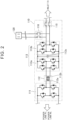
- FIG. 2 is a diagram showing an example of a circuit configuration of the bidirectional charger 110.
- the bidirectional charger 110 includes an inverter 111, an isolation circuit 112, and an inverter 113.
- the inverter 111 is a full-bridge circuit including four switching elements.
- the isolation circuit 112 is an isolation transformer including a first coil 112a and a second coil 112b.
- the isolation circuit 112 transforms a voltage at a ratio corresponding to a turns ratio between the first coil 112a and the second coil 112b.
- the inverter 113 includes a first inverter 113a, a second inverter 113b, and a smoothing capacitor 113c.
- Each of the first inverter 113a and the second inverter 113b is a full-bridge circuit including four switching elements.
- Each switching element in the inverters 111 and 113 is driven by a driver (drive circuit).
- the inverter 111 is connected to the power line PL and the power line NL, and the midpoints of the second inverter 113b are connected to the inlet 70 via a relay 115.
- the midpoints of the second inverter 113b are also connected to the in-vehicle outlet 120 via a relay 116.
- the relay 115 When charging the battery 10, the relay 115 is connected to the bidirectional charger 110.
- the second inverter 113b rectifies AC power input from the inlet 70 and outputs DC power to the first inverter 113a.
- the first inverter 113a converts the DC power received from the second inverter 113b into high-frequency AC power.
- the isolation circuit 112 transmits the output (AC power) from the first inverter 113a to the inverter 111.
- the inverter 111 rectifies the AC power received from the isolation circuit 112 and outputs DC power to the power lines PL and NL.
- the relay 116 When outputting electric power to the in-vehicle outlet 120 (during power feeding), the relay 116 is connected to the bidirectional charger 110.
- the inverter 111 converts DC power input from the power lines PL and NL into high-frequency AC power and outputs it to the isolation circuit 112.
- the isolation circuit 112 transmits the output (AC power) from the inverter 111 to the first inverter 113a.
- the first inverter 113a rectifies the AC power received from the isolation circuit 112 and outputs DC power to the second inverter 113b.
- the second inverter 113b converts the DC power received from the first inverter 113a into predetermined AC power and outputs it to the in-vehicle outlet 120.
- the in-vehicle outlet 120 is an outlet provided in a vehicle cabin and having a rated voltage of, for example, AC 100 V.
- a voltage sensor 91 detects a voltage VL between the power line PL and the power line NL
- a current sensor 92 detects a current flowing through the power line PL and the power line NL.
- a smoothing capacitor C1 is provided between the power line PL and the power line NL to smooth the voltage VL.
- a bidirectional DC-DC converter 130 is connected to the power line PL and the power line NL.
- the bidirectional DC-DC converter 130 steps down the voltage VL (voltage of the battery 10) and charges an auxiliary battery 140.
- the bidirectional DC-DC converter 130 steps up the voltage of the auxiliary battery 140 and supplies DC power to the power lines PL and NL.
- the auxiliary battery 140 is a power source for an auxiliary device 150.
- a control electronic control unit (ECU) 300 controls the SMR 11, the SMR 12, the PCU 20, the bidirectional charger 110, the bidirectional DC-DC converter 130, and the like.
- the control ECU 300 includes a central processing unit (CPU), a memory, and an input/output port (none of which is shown).
- the memory includes a read only memory (ROM) and a random access memory (RAM), and stores, for example, programs to be executed by the CPU.
- the CPU executes a predetermined calculation process based on various signals input from the input/output port, signals from various sensors, and information stored in the memory to control each device such that the electrified vehicle V becomes a desired state based on the calculation result.
- the control ECU 300 corresponds to a "control device" of the present disclosure.
- signals are input to the control ECU 300 from a power switch 90, the voltage sensor 91, the current sensor 92, and the like.
- the power switch 90 is a switch for activating a vehicle system. When the power switch 90 is operated while the system is stopped, the vehicle system is activated and the electrified vehicle V can travel. When the power switch 90 is operated while the system is operating, the vehicle system is stopped and the electrified vehicle V cannot travel.
- the power switch 90 is also referred to as "ignition switch".
- FIG. 3 is a diagram showing an example of a drive circuit 60 for the switching elements.
- FIG. 3 shows one upper and lower arm circuit including an upper arm (high-side switching element) and a lower arm (low-side switching element) in the inverter 111.
- the switching elements are used in the upper and lower arms in the full-bridge circuit or the like, power supplies of the upper arm (high-side switching element) and the lower arm (low-side switching element) need to be insulated from each other.
- a bootstrap circuit is used.
- a positive voltage power supply 61 is connected to one end of a bootstrap capacitor 65 through a diode 64 via an activation switch 66.
- the other end of the bootstrap capacitor 65 is connected to an emitter of the high-side switching element via a resistor.
- the positive voltage power supply 61 is connected to a high-side gate driver 62 via the activation switch 66.
- the high-side gate driver 62 is connected to a gate of the high-side switching element.
- the positive voltage power supply 61 is connected to a low-side gate driver 63 via the activation switch 66.
- the low-side gate driver 63 is connected to a gate of the low-side switching element.
- the present embodiment reduces the occurrence of a case where the voltage is generated in the electric circuit including the PCU 20 due to the leak current in the bidirectional charger 110 when the SMR 11 and the SMR 12 are disconnected.
- FIG. 4 is a time chart illustrating an SMR connection process of the present embodiment.
- the SMR 11 and the SMR 12 are in the disconnected state (OFF), and the battery 10 is not connected to the power lines PL and NL. Therefore, the voltage VL is 0 [V].
- An activation signal for the bidirectional charger 110 is OFF, and the bidirectional charger 110 is in a stopped state.
- the SMR connection process is started at a time t1.
- the bidirectional DC-DC converter 130 steps up the voltage of the auxiliary battery 140 and supplies DC power to the power lines PL and NL to increase the voltage VL (precharging).
- the activation signal for the bidirectional charger 110 is turned from OFF to ON, and the activation switch 66 of the drive circuit 60 is turned ON (connected), thereby activating the bidirectional charger 110.
- the predetermined period is a period in which the voltage VL increases by the operation of the bidirectional DC-DC converter 130 and the voltage is securely applied between the power lines PL and NL.
- the predetermined period is preset by experiments or the like.
- the period from the time t1 to the time t2 is a period in which the voltage VL securely increases to the battery voltage by the operation of the bidirectional DC-DC converter 130.
- the period may be predetermined by experiments or the like.
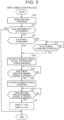
- FIG. 5 is a flowchart showing an outline of the SMR connection process to be executed by the control ECU 300.
- the process in this flowchart is started when the power switch 90 is operated to activate the vehicle system and when the connector 80 of the EVSE 100 is connected to the inlet 70.
- the SMR 11 and the SMR 12 are in the disconnected state (OFF), and the bidirectional charger 110 and the bidirectional DC-DC converter 130 are in the stopped state.
- Step 10 an initialization process is executed.
- the initialization process includes a diagnosis process for determining whether an abnormality has occurred in the PCU 20, the bidirectional charger 110, the bidirectional DC-DC converter 130, or the like, and an offset correction process (offset value learning process) for the voltage sensor 91 and the current sensor 92.
- the abnormality diagnosis for the PCU 20 is performed under the assumption that the voltage VL is 0 [V].
- the offset value (zero point) of the voltage sensor 91 is learned under the assumption that the voltage VL is 0 [V].
- S11 determination is made as to whether an abnormality has been diagnosed in the PCU 20, the bidirectional charger 110, or the like in the abnormality diagnosis of the initialization process.
- an abnormality has occurred, positive determination is made and the current routine is terminated.
- a malfunction indicator lamp MIL may be turned ON to alert a user to the abnormality in the vehicle system.
- negative determination is made and the process proceeds to S12.
- the bidirectional DC-DC converter 130 is operated.
- the bidirectional DC-DC converter 130 steps up the voltage of the auxiliary battery 140 and supplies DC power to the power lines PL and NL to increase the voltage VL (precharging).
- S15 determination is made as to whether a first predetermined period has elapsed since the bidirectional DC-DC converter 130 was operated.
- the first predetermined period is a period in which the voltage VL increases by the operation of the bidirectional DC-DC converter 130 and the voltage is securely applied between the power lines PL and NL. S15 is repeated until the first predetermined period elapses. When the first predetermined period has elapsed, positive determination is made and the process proceeds to S16.
- the bidirectional charger 110 is activated.
- the bidirectional charger 110 is activated by turning ON (connecting) the activation switch 66 of the drive circuit 60 of the bidirectional charger 110.
- S17 determination is made as to whether a second predetermined period has elapsed since the bidirectional DC-DC converter 130 was operated.
- the second predetermined period is a period in which the voltage VL securely increases to the battery voltage by the operation of the bidirectional DC-DC converter 130.
- S17 is repeated until the second predetermined period elapses.
- positive determination is made and the process proceeds to S18.
- determination may be made as to whether the voltage VL has increased to the battery voltage based on an output signal from the voltage sensor 91. When the voltage VL has increased to the battery voltage, positive determination may be made and the process may proceed to S18.
- the voltage VL after the elapse of the second predetermined period is not limited to the battery voltage.
- the voltage VL may increase by the operation of the bidirectional DC-DC converter 130 so that a large current does not flow through the contacts of the SMRs when the SMR 11 and the SMR 12 are connected.
- the bidirectional charger 110 is activated when a voltage is applied to the power lines PL and NL by the operation of the bidirectional DC-DC converter 130. As a result, it is possible to suppress the increase in the voltage on the power lines PL and NL due to the leak current from the bidirectional charger 110. Therefore, the bidirectional charger 110 is not activated when the SMR 11 and the SMR 12 that connect or disconnect the battery 10 and the PCU 20 are disconnected and no voltage is applied to the power lines PL and NL. Thus, it is possible to reduce the occurrence of the case where the voltage is generated in the electric circuit including the PCU 20 due to the leak current in the bidirectional charger 110.
- the bidirectional charger 110 When the bidirectional charger 110 is not activated, the bidirectional charger 110 is in an unstable state, and malfunction may occur due to an unintended short circuit, noise, or the like.
- the bidirectional charger 110 is activated when the SMR 11 and the SMR 12 are in the connected state and the voltage of the battery 10 (battery voltage) is applied to the power lines PL and NL. Therefore, it is possible to suppress the short circuit or malfunction of the bidirectional charger 110 when a voltage is applied to the power lines PL and NL.
- the initialization process is performed in S10 in which the SMR 11 and the SMR 12 are in the disconnected state and the bidirectional charger 110 and the bidirectional DC-DC converter 130 are in the stopped state, thereby performing the abnormality diagnosis process for the PCU 20 and the like and the offset correction process for the voltage sensor 91 and the current sensor 92. Therefore, it is possible to suppress erroneous detection and erroneous correction even if the abnormality diagnosis process and the offset correction process are executed under the assumption that the voltage of the battery 10 and the voltage caused by the leak current in the bidirectional charger 110 are not applied to the power lines PL and NL and the voltage VL is 0 [V].
- the generation of the voltage in the electric circuit including the PCU 20 due to the leak current in the bidirectional charger 110 when the SMR 11 and the SMR 12 are disconnected is suppressed in the SMR connection process.
- the generation of the voltage in the electric circuit including the PCU 20 due to the leak current in the bidirectional charger 110 is suppressed in an SMR disconnection process.
- the configuration of the electrified vehicle V is the same as that in the first embodiment.
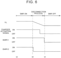
- FIG. 6 is a time chart illustrating the SMR disconnection process of the second embodiment.
- the SMR 11 and the SMR 12 are in the connected state (ON), and the battery 10 is connected to the power lines PL and NL. Therefore, the voltage VL is the voltage of the battery 10 (battery voltage).
- the activation signal for the bidirectional charger 110 is ON, and the bidirectional charger 110 is in an activated state.
- the SMR disconnection process is started at a time t4.
- the SMR 12 is switched to the disconnected state (OFF).
- the bidirectional DC-DC converter 130 steps down the voltage remaining between the power lines PL and NL and supplies it to the auxiliary battery 140.
- the voltage VL decreases over time.
- the activation signal for the bidirectional charger 110 is turned from ON to OFF, and the activation switch 66 of the drive circuit 60 is turned OFF (disconnected), thereby stopping the bidirectional charger 110.
- the predetermined period is a period in which the voltage VL decreases by the operation of the bidirectional DC-DC converter 130 so that the failure or breakage of each device does not occur even if malfunction occurs due to an unintended short circuit, noise, or the like because the bidirectional charger 110 is in an unstable state.
- the predetermined period is preset by experiments or the like.
- the SMR 11 When the voltage VL decreases approximately to 0 [V] by the operation of the bidirectional DC-DC converter 130, the SMR 11 is switched to the disconnected state (OFF) at a time t5.
- the period from the time t4 to the time t5 is a period in which the voltage VL reaches approximately 0 [V] by the operation of the bidirectional DC-DC converter 130.
- the period is predetermined by experiments or the like.
- FIG. 7 is a flowchart showing an outline of the SMR disconnection process to be executed by the control ECU 300.
- the process in this flowchart is started when the power switch 90 is operated to stop the vehicle system and when the external charging of the battery 10 is terminated.
- the SMR 11 and the SMR 12 are in the connected state (ON), and the bidirectional charger 110 is in the activated state.
- the SMR 12 When the vehicle system is stopped and when the external charging is terminated, the SMR 12 is first switched from the connected state to the disconnected state in S20, and the process proceeds to S21.
- the bidirectional DC-DC converter 130 In S21, the bidirectional DC-DC converter 130 is operated to step down the voltage remaining between the power lines PL and NL and supply it to the auxiliary battery 140.
- the third predetermined period is a period in which the voltage VL reaches a voltage at which the failure or breakage of each device does not occur even if malfunction occurs due to an unintended short circuit, noise, or the like because the bidirectional charger 110 is in an unstable state. S22 is repeated until the third predetermined period elapses. When the third predetermined period has elapsed, positive determination is made and the process proceeds to S23.
- the bidirectional charger 110 is stopped.
- the bidirectional charger 110 is stopped by turning OFF (disconnecting) the activation switch 66 of the drive circuit 60 of the bidirectional charger 110.
- S24 determination is made as to whether a fourth predetermined period has elapsed since the SMR 12 was switched to the disconnected state and the bidirectional DC-DC converter 130 was operated.
- the fourth predetermined period is a period in which the voltage VL reaches approximately 0 [V].
- S24 is repeated until the fourth predetermined period elapses.
- positive determination is made and the process proceeds to S25.
- the positive determination may be made in response to detection that the voltage VL has reached approximately 0 [V] based on the output signal from the voltage sensor 91, and the process may proceed to S25.
- the SMR 11 is switched to the disconnected state, and the current routine is terminated.
- the current routine may be terminated after the diagnosis process for determining whether an abnormality has occurred in the PCU 20, the bidirectional charger 110, the bidirectional DC-DC converter 130, or the like and the offset correction process (offset value learning process) for the voltage sensor 91 and the current sensor 92 are executed subsequently to S25 under the assumption that the voltage VL is 0 [V].
- the SMR disconnection process is started and the voltage VL decreases toward 0 [V] by the operation of the bidirectional DC-DC converter 130.
- the bidirectional charger 110 is stopped when the voltage is applied to the power lines PL and NL.
- the voltage is applied to the power lines PL and NL. Therefore, even if the leak current is generated from the bidirectional charger 110, it is possible to suppress the increase in the voltage of the electric circuit including the PCU 20 due to the leak current.
- the bidirectional charger 110 is stopped. Therefore, it is possible to suppress the generation of the voltage in the electric circuit including the PCU 20 due to the leak current in the bidirectional charger 110.
- the bidirectional charger 110 When the bidirectional charger 110 is not activated, the bidirectional charger 110 is in an unstable state, and malfunction may occur due to an unintended short circuit, noise, or the like.
- the bidirectional charger 110 is activated when the SMR 11 and the SMR 12 are in the connected state and the voltage of the battery 10 (battery voltage) is applied to the power lines PL and NL. Therefore, it is possible to suppress the short circuit or malfunction of the bidirectional charger 110 when a voltage is applied to the power lines PL and NL.
- the SMR 11 may be disconnected (OFF) at the time t4, and the SMR 12 may be disconnected (OFF) at the time t5.
- the reason why the SMR 11 and the SMR 12 are disconnected at the different timings is to securely disconnect the SMR 11 and the SMR 12 (securely detect the disconnected state of the SMR 11 and the SMR 12).
- the SMR 11 and the SMR 12 may simultaneously be disconnected (OFF) at the time t4.
- FIG. 8 is a diagram showing a configuration of an electrified vehicle according to a first modification.
- An electrified vehicle Va of the first modification differs from the electrified vehicle V of the above embodiments only in terms of the configuration of the system main relays (SMRs).
- the electrified vehicle Va includes an SMR 13 in addition to the SMR 11 and the SMR 12.
- the SMR 13 is connected in parallel with the SMR 11 to connect or disconnect the positive electrode of the battery 10 and the power line PL.
- a limiting resistor 14 is connected in series with the SMR 13.
- the SMR 13 corresponds to a "first relay" of the present disclosure
- the SMR 11 corresponds to a "second relay” of the present disclosure
- the SMR 12 corresponds to a "third relay" of the present disclosure.
- FIG. 9 is a time chart illustrating an SMR connection process in the first modification.
- the SMR 11, the SMR 12, and the SMR 13 are in the disconnected state (OFF), and the battery 10 is not connected to the power lines PL and NL. Therefore, the voltage VL is 0 [V].
- the activation signal for the bidirectional charger 110 is OFF, and the bidirectional charger 110 is in the stopped state.
- the SMR connection process is started at a time t7.
- the SMR 12 and the SMR 13 are switched to the connected state (ON). Since the limiting resistor 14 is connected in series with the SMR 13, the current flowing through the power line PL is limited, and a precharging process is performed to gradually increase the voltage VL.
- the activation signal for the bidirectional charger 110 is turned from OFF to ON, and the activation switch 66 of the drive circuit 60 is turned ON (connected), thereby activating the bidirectional charger 110.
- the predetermined period is a period in which the voltage VL increases by the precharging process and the voltage is securely applied between the power lines PL and NL.
- the predetermined period is preset by experiments or the like.
- the SMR 13 is switched to the disconnected state (OFF) and the SMR 11 is switched to the connected state (ON) at a time t8.
- the precharging period may be predetermined by experiments or the like so that the voltage VL increases by precharging and a large current does not flow through the contacts of the SMRs when the SMRs are connected.
- the bidirectional charger 110 is activated when a voltage is applied to the power lines PL and NL in the SMR connection process (during the precharging process).
- the bidirectional DC-DC converter 130 steps down the voltage remaining between the power lines PL and NL and supplies it to the auxiliary battery 140 from the time t4 to the time t5 ( FIG. 6 ) ( FIG. 7 : S21).
- the SMR 12 may be switched to the disconnected state (OFF) and a discharge resistor (discharge circuit) and the inverter 22 provided in the PCU 20 may be operated to cause the voltage VL to decrease over time.
- the same actions and effects as those in the second embodiment are attained without operating the bidirectional DC-DC converter 130.
- the electrified vehicle V of the above embodiments uses the bidirectional charger 110 to convert AC power supplied from the EVSE 100 into DC power and charge the battery 10, and to convert DC power of the battery 10 into AC power and output the AC power to the in-vehicle outlet 120.
- the electrified vehicle may use a charger that does not have the function of outputting AC power to the in-vehicle outlet 120 (charger that only has the function of charging the battery 10).
- the electrified vehicle V of the above embodiments uses the bidirectional charger 110 to convert AC power supplied from the EVSE 100 into DC power and charge the battery 10, and to convert DC power of the battery 10 into AC power and output the AC power to the in-vehicle outlet 120.
- the electrified vehicle may include a converter that has the function of outputting AC power to the in-vehicle outlet 120 (converter that does not have the function of charging the battery 10). In this case, the electrified vehicle need not include the inlet 70.
- the electrified vehicle is the battery electric vehicle (BEV) but may be any vehicle including a power storage device serving as a drive source, such as a plug-in hybrid electric vehicle (PHEV) or a hybrid electric vehicle (HEV).
- the electrified vehicle V may execute the SMR connection process of the first embodiment and the SMR disconnection process of the second embodiment.
- the electrified vehicle Va may execute the SMR connection process of the first modification and the SMR disconnection process of the second modification.
- the SMR connection processes and the SMR disconnection processes may be executed in combination as appropriate.
Abstract
An electrified vehicle (V; Va) includes: a power storage device (10); an electric motor (30) configured to drive a drive wheel (50); a drive device (20) configured to drive the electric motor (30) by using electric power in the power storage device (10); relays (11; 12; 13) configured to connect or disconnect the power storage device (10) and the drive device (20); a converter (110) connected to power lines (PL; NL) between the relays (11; 12; 13) and the drive device (20); and a control device (300) configured to activate the converter (110) or stop the converter (110) when a voltage is applied to the power lines (PL; NL) to which the converter (110) is connected.
Description
- The present disclosure relates to an electrified vehicle.
- For example, an electrified vehicle described in
Japanese Unexamined Patent Application Publication No. 2013-240191 JP 2013-240191 A JP 2013-240191 A - In the electrified vehicle disclosed in
JP 2013-240191 A - An object of the present disclosure is to prevent a voltage from being generated in an electric circuit including a drive device due to a leak current in a converter when relays that connect or disconnect a power storage device and the drive device are disconnected.
- An electrified vehicle of the present disclosure includes: a power storage device; an electric motor configured to drive a drive wheel; a drive device configured to drive the electric motor by using electric power in the power storage device; relays configured to connect or disconnect the power storage device and the drive device; a converter connected to power lines between the relays and the drive device and configured to convert alternating current power supplied from an external power supply into direct current power and charge the power storage device; and a control device configured to activate the converter or stop the converter when a voltage is applied to the power lines to which the converter is connected.
- According to this configuration, the converter is connected to the power lines between the drive device and the relays that connect or disconnect the power storage device and the drive device. The converter converts the alternating current power supplied from the external power supply into the direct current power and charges the power storage device. The control device activates the converter when the voltage is applied to the power lines to which the converter is connected. Alternatively, the control device stops the converter when the voltage is applied to the power lines to which the converter is connected.
- An electrified vehicle of the present disclosure includes: a power storage device; an electric motor configured to drive a drive wheel; a drive device configured to drive the electric motor by using electric power in the power storage device; relays configured to connect or disconnect the power storage device and the drive device; a converter connected to power lines between the relays and the drive device and configured to convert direct current power in the power storage device into alternating current power and output the alternating current power to an outlet; and a control device configured to activate the converter or stop the converter when a voltage is applied to the power lines to which the converter is connected.
- According to this configuration, the converter is connected to the power lines between the drive device and the relays that connect or disconnect the power storage device and the drive device. The converter converts the direct current power in the power storage device into the alternating current power and outputs the alternating current power to the outlet. The control device activates the converter when the voltage is applied to the power lines to which the converter is connected. Alternatively, the control device stops the converter when the voltage is applied to the power lines to which the converter is connected.
- An electrified vehicle of the present disclosure includes: a power storage device; an electric motor configured to drive a drive wheel; a drive device configured to drive the electric motor by using electric power in the power storage device; relays configured to connect or disconnect the power storage device and the drive device; a converter connected to power lines between the relays and the drive device and configured to convert alternating current power supplied from an external power supply into direct current power and charge the power storage device and to convert direct current power in the power storage device into alternating current power and output the alternating current power to an outlet; and a control device configured to activate the converter or stop the converter when a voltage is applied to the power lines to which the converter is connected.
- According to this configuration, the converter is connected to the power lines between the drive device and the relays that connect or disconnect the power storage device and the drive device. The converter is configured to convert the alternating current power supplied from the external power supply into the direct current power and charge the power storage device and to convert the direct current power in the power storage device into the alternating current power and output the alternating current power to the outlet. The control device activates the converter when the voltage is applied to the power lines to which the converter is connected. Alternatively, the control device stops the converter when the voltage is applied to the power lines to which the converter is connected.
- In the above configurations, the converter is activated when the voltage is applied to the power lines to which the converter is connected (power lines between the relays and the drive device). Even if a leak current is generated from the converter due to the activation of the converter, the voltage is applied to the power lines to which the converter is connected. Therefore, it is possible to suppress an increase in the voltage on the power lines due to the leak current. Therefore, the converter is not activated when the relays that connect or disconnect the power storage device and the drive device are disconnected and no voltage is applied to the power lines. Thus, it is possible to reduce the occurrence of the case where the voltage is generated in the electric circuit including the drive device due to the leak current in the converter.
- In the above configurations, the converter is stopped when the voltage is applied to the power lines to which the converter is connected. Therefore, when there is a possibility that a leak current is generated from the converter before the converter is stopped, that is, while the converter is activated, the voltage is applied to the power lines to which the converter is connected. Thus, even if the leak current is generated from the converter, it is possible to suppress the increase in the voltage on the power lines due to the leak current. Further, the converter is stopped when the relays that connect or disconnect the power storage device and the drive device are disconnected and no voltage is applied to the power lines. Thus, it is possible to reduce the occurrence of the case where the voltage is generated in the electric circuit including the drive device due to the leak current in the converter. Therefore, when the relays that connect or disconnect the power storage device and the drive device are disconnected, it is possible to reduce the occurrence of the case where the voltage is generated in the electric circuit including the drive device due to the leak current in the converter.
- The electrified vehicle of the present disclosure may further include: an auxiliary battery configured to supply electric power to an auxiliary device; and a bidirectional direct current-to-direct current converter configured to transfer electric power between the auxiliary battery and the power lines. The control device may be configured to execute a connection process for switching each of the relays from a disconnected state to a connected state. The connection process may include a process of stepping up the electric power in the auxiliary battery by the bidirectional direct current-to-direct current converter to increase the voltage on the power lines and activating the converter, and a process of switching the relays from the disconnected state to the connected state after the voltage on the power lines has increased to a predetermined value.
- According to this configuration, the control device executes the connection process for switching each of the relays from the disconnected state to the connected state. The connection process includes the processes of stepping up the electric power in the auxiliary battery by the bidirectional direct current-to-direct current converter to increase the voltage on the power lines and activating the converter, and switching the relays from the disconnected state to the connected state after the voltage on the power lines has increased to the predetermined value.
- In the connection process, the electric power in the auxiliary battery is stepped up by the bidirectional direct current-to-direct current converter to increase the voltage on the power lines and the converter is activated. The relays are switched from the disconnected state to the connected state after the voltage on the power lines has increased to the predetermined value. When the relays that connect or disconnect the power storage device and the drive device are disconnected, the converter is in the stopped state, and the voltage is not generated on the power lines to which the converter is connected due to the leak current from the converter.
- When the converter is not activated, the converter is in an unstable state, and malfunction may occur due to an unintended short circuit, noise, or the like. According to this configuration, the converter is activated when the relays are in the connected state and the voltage of the power storage device is applied to the power lines. Therefore, it is possible to suppress the short circuit or malfunction of the converter when the voltage is applied to the power lines to which the converter is connected (power lines between the relays and the drive device).
- The electrified vehicle of the present disclosure may further include: an auxiliary battery configured to supply electric power to an auxiliary device; and a bidirectional direct current-to-direct current converter configured to transfer electric power between the auxiliary battery and the power lines. The control device may be configured to execute a disconnection process for switching each of the relays from a connected state to a disconnected state. The disconnection process may include a process of, after the relays have been switched from the connected state to the disconnected state, supplying the electric power on the power lines to the auxiliary battery by the bidirectional direct current-to-direct current converter to step down the voltage on the power lines and stopping the converter.
- According to this configuration, the control device executes the disconnection process for switching each of the relays from the connected state to the disconnected state. The disconnection process includes the process of, after the relays have been switched from the connected state to the disconnected state, supplying the electric power on the power lines to the auxiliary battery by the bidirectional direct current-to-direct current converter to step down the voltage on the power lines and stopping the converter.
- In the disconnection process, after the relays have been switched from the connected state to the disconnected state, the electric power on the power lines is supplied to the auxiliary battery by the bidirectional direct current-to-direct current converter to step down the voltage on the power lines and the converter is stopped. When the relays that connect or disconnect the power storage device and the drive device are disconnected, the converter is in the stopped state, and the voltage is not generated on the power lines to which the converter is connected due to the leak current from the converter. Further, the converter is activated when the relays are in the connected state and the voltage of the power storage device is applied to the power lines. Therefore, it is possible to suppress the short circuit or malfunction of the converter when the voltage is applied to the power lines.
- In the electrified vehicle of the present disclosure, the relays may include a circuit including a first relay configured to connect or disconnect one pole of the power storage device and the drive device and a limiting resistor connected in series with the first relay, a second relay connected in parallel with the circuit, and a third relay configured to connect or disconnect another pole of the power storage device and the drive device. The control device may be configured to execute a connection process for switching each of the relays from a disconnected state to a connected state. The connection process may include a process of performing a precharging process for switching the first relay and the third relay from the disconnected state to the connected state and activating the converter, and a process of, after the precharging process has been finished, switching the second relay from the disconnected state to the connected state and switching the first relay to the disconnected state.
- According to this configuration, in the connection process, the precharging process is performed to switch the first relay and the third relay from the disconnected state to the connected state. The control device activates the converter along with the precharging process. After the precharging process has been finished, the control device switches the second relay from the disconnected state to the connected state and switches the first relay to the disconnected state. Then, the control device terminates the connection process.
- In the connection process, the voltage on the power lines to which the converter is connected (power lines between the relays and the drive device) is increased by the precharging process, and the converter is activated. After the precharging process has been finished, the second relay is switched from the disconnected state to the connected state and the first relay is switched to the disconnected state. Then, the connection process is terminated. When the relays that connect or disconnect the power storage device and the drive device are disconnected, the converter is in the stopped state, and the voltage is not generated on the power lines to which the converter is connected due to the leak current from the converter.
- When the converter is not activated, the converter is in an unstable state, and malfunction may occur due to an unintended short circuit, noise, or the like. According to this configuration, the converter is activated when the relays are in the connected state and the voltage of the power storage device is applied to the power lines. Therefore, it is possible to suppress the short circuit or malfunction of the converter when the voltage is applied to the power lines.
- In the electrified vehicle of the present disclosure, the control device may be configured to execute a disconnection process for switching each of the relays from a connected state to a disconnected state. The disconnection process may include a process of switching a relay configured to connect or disconnect one pole of the power storage device and the drive device from the connected state to the disconnected state and, after an elapse of a predetermined period, switching a relay configured to connect or disconnect another pole of the power storage device and the drive device from the connected state to the disconnected state, and a process of stopping the converter within the predetermined period.
- According to this configuration, the control device executes the disconnection process for switching each of the relays from the connected state to the disconnected state. In the disconnection process, the relay configured to connect or disconnect one pole of the power storage device and the drive device is switched from the connected state to the disconnected state and, after the elapse of the predetermined period, the relay configured to connect or disconnect another pole of the power storage device and the drive device is switched from the connected state to the disconnected state. Then, the converter is stopped within the predetermined period in the disconnection process. When both the poles of the power storage device and the drive device are disconnected, the converter is in the stopped state, and the voltage is not generated on the power lines to which the converter is connected due to the leak current from the converter. Further, the converter is activated when the relays are in the connected state and the voltage of the power storage device is applied to the power lines. Therefore, it is possible to suppress the short circuit or malfunction of the converter when the voltage is applied to the power lines.
- In the electrified vehicle of the present disclosure, the control device may be configured to, when all the relays configured to connect or disconnect the power storage device and the drive device are in a disconnected state, execute an abnormality detection process for the drive device or an offset correction process for sensors provided in an electric circuit including the drive device.
- When all the relays configured to connect or disconnect the power storage device and the drive device are in the disconnected state and the abnormality detection process for the drive device or the offset correction process for the sensors provided in the electric circuit including the drive device is executed under the assumption that no voltage is generated in the electric circuit including the drive device, erroneous detection or erroneous correction may occur if a voltage is generated in the electric circuit due to the leak current in the converter.
- According to this configuration, when the relays are in the disconnected state, the converter is in the stopped state and the voltage is not generated on the power lines to which the converter is connected due to the leak current from the converter. Even if the abnormality detection process or the offset correction process is executed under the assumption that no voltage is generated in the electric circuit including the drive device, the erroneous detection or the erroneous correction can be suppressed.
- According to the present disclosure, it is possible to prevent the voltage from being generated in the electric circuit including the drive device due to the leak current in the converter when the relays that connect or disconnect the power storage device and the drive device are disconnected.
- Features, advantages, and technical and industrial significance of exemplary embodiments of the invention will be described below with reference to the accompanying drawings, in which like signs denote like elements, and wherein:
-
FIG. 1 is a diagram showing a configuration of an electrified vehicle according to an embodiment of the present disclosure; -
FIG. 2 is a diagram showing an example of a circuit configuration of a bidirectional charger; -
FIG. 3 is a diagram showing an example of a drive circuit for switching elements; -
FIG. 4 is a time chart illustrating a system main relay (SMR) connection process of a first embodiment; -
FIG. 5 is a flowchart showing an outline of the SMR connection process to be executed by a control electronic control unit (ECU); -
FIG. 6 is a time chart illustrating an SMR disconnection process of a second embodiment; -
FIG. 7 is a flowchart showing an outline of the SMR disconnection process to be executed by the control ECU; -
FIG. 8 is a diagram showing a configuration of an electrified vehicle according to a first modification; and -
FIG. 9 is a time chart illustrating an SMR connection process in the first modification. - Embodiments of the present disclosure will be described in detail below with reference to the drawings. The same or corresponding parts are denoted by the same signs throughout the drawings, and description thereof will not be repeated.
-
FIG. 1 is a diagram showing a configuration of an electrified vehicle V according to a first embodiment of the present disclosure. Referring toFIG. 1 , the electrified vehicle V includes abattery 10, a power control unit (hereinafter also referred to as "PCU") 20, amotor generator 30, adifferential gear 40, and drivewheels 50. - The
battery 10 is a power storage device, and is mounted on the electrified vehicle V as a drive power supply. Thebattery 10 includes a plurality of stacked single cells. The cell is a secondary battery such as a nickel metal hydride battery or a lithium ion battery. The cell may be a battery having a liquid electrolyte between a positive electrode and a negative electrode, or may be a battery having a solid electrolyte between a positive electrode and a negative electrode (solid-state battery). - The
PCU 20 is a drive device that drives themotor generator 30 by using electric power stored in thebattery 10. Thebattery 10 and thePCU 20 are connected by a power line PL and a power line NL. The positive electrode of thebattery 10 and the power line PL are connected via a system main relay (SMR) 11. The negative electrode of thebattery 10 and the power line NL are connected via a system main relay (SMR) 12. For example, theSMR 11 and theSMR 12 may be electromagnetic mechanical relays. When theSMR 11 and theSMR 12 are in a connected state, electric power can be transferred between thebattery 10 and thePCU 20. When theSMR 11 and theSMR 12 are in a disconnected state, electric power cannot be transferred between thebattery 10 and thePCU 20. - In the present embodiment, the
PCU 20 includes a direct current-to-direct current (DC-DC)converter 21 and aninverter 22. The DC-DC converter 21 steps up a DC voltage of thebattery 10 and supplies it to theinverter 22. Theinverter 22 is a three-phase inverter that converts DC power supplied from thebattery 10 into alternating current (AC) power to drive themotor generator 30. Theinverter 22 converts AC power regenerated by themotor generator 30 into DC power, and supplies it to thebattery 10 via the DC-DC converter 21. The DC-DC converter 21 may be omitted. - The
motor generator 30 is an AC rotary electric machine and corresponds to an "electric motor" of the present disclosure. Examples of themotor generator 30 include a permanent magnet type synchronous motor including a rotor with embedded permanent magnets. An output shaft of themotor generator 30 is connected to thedrive wheels 50 via thedifferential gear 40. Thedrive wheels 50 are driven by themotor generator 30. - The electrified vehicle V can charge the
battery 10 by using anexternal power supply 200. The charging of thebattery 10 by theexternal power supply 200 is also referred to as "external charging". The electrified vehicle V includes aninlet 70. The external charging is performed by connecting aconnector 80 of charging equipment (electric vehicle supply equipment (EVSE)) 100 to theinlet 70. TheEVSE 100 may be a charging cable with a control function or a general charger. Theexternal power supply 200 may be, for example, an AC 200 V power supply. - A
bidirectional charger 110 is connected to the power line PL (power line between theSMR 11 and the PCU 20) and the power line NL (power line between theSMR 12 and the PCU 20). Thebidirectional charger 110 converts AC power supplied from theEVSE 100 via theinlet 70 into DC power and charges thebattery 10. Thebidirectional charger 110 also converts DC power of thebattery 10 into AC power and outputs the AC power to an in-vehicle outlet 120. Thebidirectional charger 110 corresponds to a "converter" of the present disclosure. The in-vehicle outlet 120 corresponds to an "outlet" of the present disclosure. -
FIG. 2 is a diagram showing an example of a circuit configuration of thebidirectional charger 110. Thebidirectional charger 110 includes aninverter 111, anisolation circuit 112, and aninverter 113. Theinverter 111 is a full-bridge circuit including four switching elements. Theisolation circuit 112 is an isolation transformer including afirst coil 112a and asecond coil 112b. Theisolation circuit 112 transforms a voltage at a ratio corresponding to a turns ratio between thefirst coil 112a and thesecond coil 112b. Theinverter 113 includes afirst inverter 113a, asecond inverter 113b, and a smoothingcapacitor 113c. Each of thefirst inverter 113a and thesecond inverter 113b is a full-bridge circuit including four switching elements. Each switching element in theinverters - The
inverter 111 is connected to the power line PL and the power line NL, and the midpoints of thesecond inverter 113b are connected to theinlet 70 via arelay 115. The midpoints of thesecond inverter 113b are also connected to the in-vehicle outlet 120 via arelay 116. - When charging the
battery 10, therelay 115 is connected to thebidirectional charger 110. Thesecond inverter 113b rectifies AC power input from theinlet 70 and outputs DC power to thefirst inverter 113a. Thefirst inverter 113a converts the DC power received from thesecond inverter 113b into high-frequency AC power. Theisolation circuit 112 transmits the output (AC power) from thefirst inverter 113a to theinverter 111. Theinverter 111 rectifies the AC power received from theisolation circuit 112 and outputs DC power to the power lines PL and NL. - When outputting electric power to the in-vehicle outlet 120 (during power feeding), the
relay 116 is connected to thebidirectional charger 110. Theinverter 111 converts DC power input from the power lines PL and NL into high-frequency AC power and outputs it to theisolation circuit 112. Theisolation circuit 112 transmits the output (AC power) from theinverter 111 to thefirst inverter 113a. Thefirst inverter 113a rectifies the AC power received from theisolation circuit 112 and outputs DC power to thesecond inverter 113b. Thesecond inverter 113b converts the DC power received from thefirst inverter 113a into predetermined AC power and outputs it to the in-vehicle outlet 120. The in-vehicle outlet 120 is an outlet provided in a vehicle cabin and having a rated voltage of, for example, AC 100 V. - Referring to
FIG. 1 again, a voltage sensor 91 detects a voltage VL between the power line PL and the power line NL, and acurrent sensor 92 detects a current flowing through the power line PL and the power line NL. A smoothing capacitor C1 is provided between the power line PL and the power line NL to smooth the voltage VL. - A bidirectional DC-
DC converter 130 is connected to the power line PL and the power line NL. The bidirectional DC-DC converter 130 steps down the voltage VL (voltage of the battery 10) and charges anauxiliary battery 140. The bidirectional DC-DC converter 130 steps up the voltage of theauxiliary battery 140 and supplies DC power to the power lines PL and NL. Theauxiliary battery 140 is a power source for anauxiliary device 150. - A control electronic control unit (ECU) 300 controls the
SMR 11, theSMR 12, thePCU 20, thebidirectional charger 110, the bidirectional DC-DC converter 130, and the like. Thecontrol ECU 300 includes a central processing unit (CPU), a memory, and an input/output port (none of which is shown). The memory includes a read only memory (ROM) and a random access memory (RAM), and stores, for example, programs to be executed by the CPU. The CPU executes a predetermined calculation process based on various signals input from the input/output port, signals from various sensors, and information stored in the memory to control each device such that the electrified vehicle V becomes a desired state based on the calculation result. Thecontrol ECU 300 corresponds to a "control device" of the present disclosure. - In the present embodiment, signals are input to the
control ECU 300 from apower switch 90, the voltage sensor 91, thecurrent sensor 92, and the like. Thepower switch 90 is a switch for activating a vehicle system. When thepower switch 90 is operated while the system is stopped, the vehicle system is activated and the electrified vehicle V can travel. When thepower switch 90 is operated while the system is operating, the vehicle system is stopped and the electrified vehicle V cannot travel. Thepower switch 90 is also referred to as "ignition switch". - When the
bidirectional charger 110 is activated, a voltage may be generated on the power lines PL and NL due to a leak current in the driver (drive circuit) for the switching elements of theinverter 111 constituting thebidirectional charger 110.FIG. 3 is a diagram showing an example of adrive circuit 60 for the switching elements.FIG. 3 shows one upper and lower arm circuit including an upper arm (high-side switching element) and a lower arm (low-side switching element) in theinverter 111. When the switching elements are used in the upper and lower arms in the full-bridge circuit or the like, power supplies of the upper arm (high-side switching element) and the lower arm (low-side switching element) need to be insulated from each other. In the present embodiment, a bootstrap circuit is used. - In
FIG. 3 , a positivevoltage power supply 61 is connected to one end of abootstrap capacitor 65 through adiode 64 via anactivation switch 66. The other end of thebootstrap capacitor 65 is connected to an emitter of the high-side switching element via a resistor. The positivevoltage power supply 61 is connected to a high-side gate driver 62 via theactivation switch 66. The high-side gate driver 62 is connected to a gate of the high-side switching element. The positivevoltage power supply 61 is connected to a low-side gate driver 63 via theactivation switch 66. The low-side gate driver 63 is connected to a gate of the low-side switching element. - When the
activation switch 66 of thedrive circuit 60 is turned ON to operate thebidirectional charger 110, a current flows from the positivevoltage power supply 61 along a path indicated by an arrow of a long dashed short dashed line inFIG. 3 . Therefore, a leak current is generated. Due to this leak current, a voltage may be generated on the power lines PL and NL even when theSMR 11 and theSMR 12 are in the disconnected state. Thus, a voltage may be generated in the electric circuit including thePCU 20. - The present embodiment reduces the occurrence of a case where the voltage is generated in the electric circuit including the
PCU 20 due to the leak current in thebidirectional charger 110 when theSMR 11 and theSMR 12 are disconnected. -
FIG. 4 is a time chart illustrating an SMR connection process of the present embodiment. At a time t0, theSMR 11 and theSMR 12 are in the disconnected state (OFF), and thebattery 10 is not connected to the power lines PL and NL. Therefore, the voltage VL is 0 [V]. An activation signal for thebidirectional charger 110 is OFF, and thebidirectional charger 110 is in a stopped state. - When the
power switch 90 is operated to activate the vehicle system or when theconnector 80 of theEVSE 100 is connected to theinlet 70 to start charging thebattery 10, the SMR connection process is started at a time t1. When the SMR connection process is started at thetime 11, the bidirectional DC-DC converter 130 steps up the voltage of theauxiliary battery 140 and supplies DC power to the power lines PL and NL to increase the voltage VL (precharging). After a predetermined period has elapsed from thetime 11, the activation signal for thebidirectional charger 110 is turned from OFF to ON, and theactivation switch 66 of thedrive circuit 60 is turned ON (connected), thereby activating thebidirectional charger 110. The predetermined period is a period in which the voltage VL increases by the operation of the bidirectional DC-DC converter 130 and the voltage is securely applied between the power lines PL and NL. The predetermined period is preset by experiments or the like. - When the voltage VL increases approximately to the voltage of the battery 10 (battery voltage) by the operation of the bidirectional DC-
DC converter 130, theSMR 11 and theSMR 12 are switched to the connected state at a time t2. The period from the time t1 to the time t2 is a period in which the voltage VL securely increases to the battery voltage by the operation of the bidirectional DC-DC converter 130. The period may be predetermined by experiments or the like. -
FIG. 5 is a flowchart showing an outline of the SMR connection process to be executed by thecontrol ECU 300. The process in this flowchart is started when thepower switch 90 is operated to activate the vehicle system and when theconnector 80 of theEVSE 100 is connected to theinlet 70. Before the SMR connection process is started, theSMR 11 and theSMR 12 are in the disconnected state (OFF), and thebidirectional charger 110 and the bidirectional DC-DC converter 130 are in the stopped state. - In Step (hereinafter abbreviated as "S") 10, an initialization process is executed. The initialization process includes a diagnosis process for determining whether an abnormality has occurred in the
PCU 20, thebidirectional charger 110, the bidirectional DC-DC converter 130, or the like, and an offset correction process (offset value learning process) for the voltage sensor 91 and thecurrent sensor 92. For example, the abnormality diagnosis for thePCU 20 is performed under the assumption that the voltage VL is 0 [V]. Further, the offset value (zero point) of the voltage sensor 91 is learned under the assumption that the voltage VL is 0 [V]. - In S11, determination is made as to whether an abnormality has been diagnosed in the
PCU 20, thebidirectional charger 110, or the like in the abnormality diagnosis of the initialization process. When an abnormality has occurred, positive determination is made and the current routine is terminated. In this case, a malfunction indicator lamp (MIL) may be turned ON to alert a user to the abnormality in the vehicle system. When no abnormality has occurred, negative determination is made and the process proceeds to S12. - In S12, determination is made as to whether the current process is the external charging. When the
connector 80 is connected to theinlet 70, determination is made that the current process is the external charging (positive determination), and the process proceeds to S13. When theconnector 80 is not connected to theinlet 70, negative determination is made and the process proceeds to S14. - In S13, determination is made as to whether the timing to start the external charging has come. For example, in a case where timer charging is set, determination is made that the timing to start the external charging has come at a charging start time.
S 13 is repeated until the timing to start the external charging comes. When the timing to start the external charging has come, positive determination is made and the process proceeds to S14. - In S14, the bidirectional DC-
DC converter 130 is operated. The bidirectional DC-DC converter 130 steps up the voltage of theauxiliary battery 140 and supplies DC power to the power lines PL and NL to increase the voltage VL (precharging). - In S15, determination is made as to whether a first predetermined period has elapsed since the bidirectional DC-
DC converter 130 was operated. The first predetermined period is a period in which the voltage VL increases by the operation of the bidirectional DC-DC converter 130 and the voltage is securely applied between the power lines PL and NL. S15 is repeated until the first predetermined period elapses. When the first predetermined period has elapsed, positive determination is made and the process proceeds to S16. - In S16, the
bidirectional charger 110 is activated. Thebidirectional charger 110 is activated by turning ON (connecting) theactivation switch 66 of thedrive circuit 60 of thebidirectional charger 110. - In S17, determination is made as to whether a second predetermined period has elapsed since the bidirectional DC-
DC converter 130 was operated. The second predetermined period is a period in which the voltage VL securely increases to the battery voltage by the operation of the bidirectional DC-DC converter 130. S17 is repeated until the second predetermined period elapses. When the second predetermined period has elapsed, positive determination is made and the process proceeds to S18. In S17, determination may be made as to whether the voltage VL has increased to the battery voltage based on an output signal from the voltage sensor 91. When the voltage VL has increased to the battery voltage, positive determination may be made and the process may proceed to S18. The voltage VL after the elapse of the second predetermined period is not limited to the battery voltage. The voltage VL may increase by the operation of the bidirectional DC-DC converter 130 so that a large current does not flow through the contacts of the SMRs when theSMR 11 and theSMR 12 are connected. - In S18, the
SMR 11 and theSMR 12 are switched to the connected state, and the current routine is terminated. - In the present embodiment, the
bidirectional charger 110 is activated when a voltage is applied to the power lines PL and NL by the operation of the bidirectional DC-DC converter 130. As a result, it is possible to suppress the increase in the voltage on the power lines PL and NL due to the leak current from thebidirectional charger 110. Therefore, thebidirectional charger 110 is not activated when theSMR 11 and theSMR 12 that connect or disconnect thebattery 10 and thePCU 20 are disconnected and no voltage is applied to the power lines PL and NL. Thus, it is possible to reduce the occurrence of the case where the voltage is generated in the electric circuit including thePCU 20 due to the leak current in thebidirectional charger 110. - When the
bidirectional charger 110 is not activated, thebidirectional charger 110 is in an unstable state, and malfunction may occur due to an unintended short circuit, noise, or the like. According to the present embodiment, thebidirectional charger 110 is activated when theSMR 11 and theSMR 12 are in the connected state and the voltage of the battery 10 (battery voltage) is applied to the power lines PL and NL. Therefore, it is possible to suppress the short circuit or malfunction of thebidirectional charger 110 when a voltage is applied to the power lines PL and NL. - According to the present embodiment, the initialization process is performed in S10 in which the
SMR 11 and theSMR 12 are in the disconnected state and thebidirectional charger 110 and the bidirectional DC-DC converter 130 are in the stopped state, thereby performing the abnormality diagnosis process for thePCU 20 and the like and the offset correction process for the voltage sensor 91 and thecurrent sensor 92. Therefore, it is possible to suppress erroneous detection and erroneous correction even if the abnormality diagnosis process and the offset correction process are executed under the assumption that the voltage of thebattery 10 and the voltage caused by the leak current in thebidirectional charger 110 are not applied to the power lines PL and NL and the voltage VL is 0 [V]. - In the above embodiment (first embodiment), the generation of the voltage in the electric circuit including the
PCU 20 due to the leak current in thebidirectional charger 110 when theSMR 11 and theSMR 12 are disconnected is suppressed in the SMR connection process. In a second embodiment, the generation of the voltage in the electric circuit including thePCU 20 due to the leak current in thebidirectional charger 110 is suppressed in an SMR disconnection process. The configuration of the electrified vehicle V is the same as that in the first embodiment. -
FIG. 6 is a time chart illustrating the SMR disconnection process of the second embodiment. At a time t3, theSMR 11 and theSMR 12 are in the connected state (ON), and thebattery 10 is connected to the power lines PL and NL. Therefore, the voltage VL is the voltage of the battery 10 (battery voltage). The activation signal for thebidirectional charger 110 is ON, and thebidirectional charger 110 is in an activated state. - When the
power switch 90 is operated to stop the vehicle system or when the external charging of thebattery 10 is terminated, the SMR disconnection process is started at a time t4. When the SMR disconnection process is started at the time t4, theSMR 12 is switched to the disconnected state (OFF). At the time t4, the bidirectional DC-DC converter 130 steps down the voltage remaining between the power lines PL and NL and supplies it to theauxiliary battery 140. Thus, the voltage VL decreases over time. After a predetermined period has elapsed from the time t4, the activation signal for thebidirectional charger 110 is turned from ON to OFF, and theactivation switch 66 of thedrive circuit 60 is turned OFF (disconnected), thereby stopping thebidirectional charger 110. The predetermined period is a period in which the voltage VL decreases by the operation of the bidirectional DC-DC converter 130 so that the failure or breakage of each device does not occur even if malfunction occurs due to an unintended short circuit, noise, or the like because thebidirectional charger 110 is in an unstable state. The predetermined period is preset by experiments or the like. - When the voltage VL decreases approximately to 0 [V] by the operation of the bidirectional DC-
DC converter 130, theSMR 11 is switched to the disconnected state (OFF) at a time t5. The period from the time t4 to the time t5 is a period in which the voltage VL reaches approximately 0 [V] by the operation of the bidirectional DC-DC converter 130. The period is predetermined by experiments or the like. -
FIG. 7 is a flowchart showing an outline of the SMR disconnection process to be executed by thecontrol ECU 300. The process in this flowchart is started when thepower switch 90 is operated to stop the vehicle system and when the external charging of thebattery 10 is terminated. Before the SMR disconnection process is started, theSMR 11 and theSMR 12 are in the connected state (ON), and thebidirectional charger 110 is in the activated state. - When the vehicle system is stopped and when the external charging is terminated, the
SMR 12 is first switched from the connected state to the disconnected state in S20, and the process proceeds to S21. In S21, the bidirectional DC-DC converter 130 is operated to step down the voltage remaining between the power lines PL and NL and supply it to theauxiliary battery 140. - In S22, determination is made as to whether a third predetermined period has elapsed since the
SMR 12 was switched to the disconnected state and the bidirectional DC-DC converter 130 was operated. The third predetermined period is a period in which the voltage VL reaches a voltage at which the failure or breakage of each device does not occur even if malfunction occurs due to an unintended short circuit, noise, or the like because thebidirectional charger 110 is in an unstable state. S22 is repeated until the third predetermined period elapses. When the third predetermined period has elapsed, positive determination is made and the process proceeds to S23. - In S23, the
bidirectional charger 110 is stopped. Thebidirectional charger 110 is stopped by turning OFF (disconnecting) theactivation switch 66 of thedrive circuit 60 of thebidirectional charger 110. - In S24, determination is made as to whether a fourth predetermined period has elapsed since the
SMR 12 was switched to the disconnected state and the bidirectional DC-DC converter 130 was operated. The fourth predetermined period is a period in which the voltage VL reaches approximately 0 [V]. S24 is repeated until the fourth predetermined period elapses. When the fourth predetermined period has elapsed, positive determination is made and the process proceeds to S25. In S24, the positive determination may be made in response to detection that the voltage VL has reached approximately 0 [V] based on the output signal from the voltage sensor 91, and the process may proceed to S25. - In S25, the
SMR 11 is switched to the disconnected state, and the current routine is terminated. The current routine may be terminated after the diagnosis process for determining whether an abnormality has occurred in thePCU 20, thebidirectional charger 110, the bidirectional DC-DC converter 130, or the like and the offset correction process (offset value learning process) for the voltage sensor 91 and thecurrent sensor 92 are executed subsequently to S25 under the assumption that the voltage VL is 0 [V]. - According to the second embodiment, the SMR disconnection process is started and the voltage VL decreases toward 0 [V] by the operation of the bidirectional DC-
DC converter 130. Thebidirectional charger 110 is stopped when the voltage is applied to the power lines PL and NL. When there is a possibility that a leak current is generated from thebidirectional charger 110 before thebidirectional charger 110 is stopped, that is, while thebidirectional charger 110 is activated, the voltage is applied to the power lines PL and NL. Therefore, even if the leak current is generated from thebidirectional charger 110, it is possible to suppress the increase in the voltage of the electric circuit including thePCU 20 due to the leak current. When theSMR 11 and theSMR 12 are disconnected and no voltage is applied to the power lines PL and NL, thebidirectional charger 110 is stopped. Therefore, it is possible to suppress the generation of the voltage in the electric circuit including thePCU 20 due to the leak current in thebidirectional charger 110. - When the
bidirectional charger 110 is not activated, thebidirectional charger 110 is in an unstable state, and malfunction may occur due to an unintended short circuit, noise, or the like. According to the second embodiment, thebidirectional charger 110 is activated when theSMR 11 and theSMR 12 are in the connected state and the voltage of the battery 10 (battery voltage) is applied to the power lines PL and NL. Therefore, it is possible to suppress the short circuit or malfunction of thebidirectional charger 110 when a voltage is applied to the power lines PL and NL. - In the second embodiment, the
SMR 11 may be disconnected (OFF) at the time t4, and theSMR 12 may be disconnected (OFF) at the time t5. The reason why theSMR 11 and theSMR 12 are disconnected at the different timings is to securely disconnect theSMR 11 and the SMR 12 (securely detect the disconnected state of theSMR 11 and the SMR 12). TheSMR 11 and theSMR 12 may simultaneously be disconnected (OFF) at the time t4. -
FIG. 8 is a diagram showing a configuration of an electrified vehicle according to a first modification. An electrified vehicle Va of the first modification differs from the electrified vehicle V of the above embodiments only in terms of the configuration of the system main relays (SMRs). InFIG. 8 , the electrified vehicle Va includes anSMR 13 in addition to theSMR 11 and theSMR 12. TheSMR 13 is connected in parallel with theSMR 11 to connect or disconnect the positive electrode of thebattery 10 and the power line PL. A limitingresistor 14 is connected in series with theSMR 13. In the first modification, theSMR 13 corresponds to a "first relay" of the present disclosure, theSMR 11 corresponds to a "second relay" of the present disclosure, and theSMR 12 corresponds to a "third relay" of the present disclosure. -
FIG. 9 is a time chart illustrating an SMR connection process in the first modification. At a time t6, theSMR 11, theSMR 12, and theSMR 13 are in the disconnected state (OFF), and thebattery 10 is not connected to the power lines PL and NL. Therefore, the voltage VL is 0 [V]. The activation signal for thebidirectional charger 110 is OFF, and thebidirectional charger 110 is in the stopped state. - When the
power switch 90 is operated to activate the vehicle system or when theconnector 80 of theEVSE 100 is connected to theinlet 70 to start charging thebattery 10, the SMR connection process is started at a time t7. When the SMR connection process is started at the time t7, theSMR 12 and theSMR 13 are switched to the connected state (ON). Since the limitingresistor 14 is connected in series with theSMR 13, the current flowing through the power line PL is limited, and a precharging process is performed to gradually increase the voltage VL. After a predetermined period has elapsed from the time t7, the activation signal for thebidirectional charger 110 is turned from OFF to ON, and theactivation switch 66 of thedrive circuit 60 is turned ON (connected), thereby activating thebidirectional charger 110. The predetermined period is a period in which the voltage VL increases by the precharging process and the voltage is securely applied between the power lines PL and NL. The predetermined period is preset by experiments or the like. - When the precharging period has ended, the
SMR 13 is switched to the disconnected state (OFF) and theSMR 11 is switched to the connected state (ON) at a time t8. The precharging period may be predetermined by experiments or the like so that the voltage VL increases by precharging and a large current does not flow through the contacts of the SMRs when the SMRs are connected. - In the first modification as well, the
bidirectional charger 110 is activated when a voltage is applied to the power lines PL and NL in the SMR connection process (during the precharging process). Thus, the same actions and effects as those in the first embodiment are attained. - In the second embodiment, the bidirectional DC-
DC converter 130 steps down the voltage remaining between the power lines PL and NL and supplies it to theauxiliary battery 140 from the time t4 to the time t5 (FIG. 6 ) (FIG. 7 : S21). When the SMR disconnection process is started at the time t4, theSMR 12 may be switched to the disconnected state (OFF) and a discharge resistor (discharge circuit) and theinverter 22 provided in thePCU 20 may be operated to cause the voltage VL to decrease over time. According to the second modification, the same actions and effects as those in the second embodiment are attained without operating the bidirectional DC-DC converter 130. - The electrified vehicle V of the above embodiments uses the
bidirectional charger 110 to convert AC power supplied from theEVSE 100 into DC power and charge thebattery 10, and to convert DC power of thebattery 10 into AC power and output the AC power to the in-vehicle outlet 120. Instead of thebidirectional charger 110, the electrified vehicle may use a charger that does not have the function of outputting AC power to the in-vehicle outlet 120 (charger that only has the function of charging the battery 10). - The electrified vehicle V of the above embodiments uses the
bidirectional charger 110 to convert AC power supplied from theEVSE 100 into DC power and charge thebattery 10, and to convert DC power of thebattery 10 into AC power and output the AC power to the in-vehicle outlet 120. Instead of thebidirectional charger 110, the electrified vehicle may include a converter that has the function of outputting AC power to the in-vehicle outlet 120 (converter that does not have the function of charging the battery 10). In this case, the electrified vehicle need not include theinlet 70. - In the above embodiments, the electrified vehicle is the battery electric vehicle (BEV) but may be any vehicle including a power storage device serving as a drive source, such as a plug-in hybrid electric vehicle (PHEV) or a hybrid electric vehicle (HEV). The electrified vehicle V may execute the SMR connection process of the first embodiment and the SMR disconnection process of the second embodiment. The electrified vehicle Va may execute the SMR connection process of the first modification and the SMR disconnection process of the second modification. Alternatively, the SMR connection processes and the SMR disconnection processes may be executed in combination as appropriate.
- The embodiments disclosed herein shall be construed as illustrative and not restrictive in all respects. The scope of the present invention is shown by the claims rather than by the above description of the embodiments and is intended to include all modifications within the meaning and scope equivalent to those of the claims.
Claims (6)
- An electrified vehicle (V; Va) comprising:a power storage device (10);an electric motor (30) configured to drive a drive wheel (50);a drive device (20) configured to drive the electric motor (30) by using electric power in the power storage device (10);relays (11; 12; 13) configured to connect or disconnect the power storage device (10) and the drive device (20);a converter (110) connected to power lines (PL; NL) between the relays (11; 12; 13) and the drive device (20); anda control device (300) configured to activate the converter (110) or stop the converter (110) when a voltage is applied to the power lines (PL; NL) to which the converter (110) is connected, wherein
the converter (110) is configured to convert alternating current power supplied from an external power supply (200) into direct current power and charge the power storage device (10), and/or is configured to convert direct current power in the power storage device (10) into alternating current power and output the alternating current power to an outlet (120). - The electrified vehicle (V; Va) according to claim 1, further comprising:an auxiliary battery (140) configured to supply electric power to an auxiliary device (150); anda bidirectional direct current-to-direct current converter (130) configured to transfer electric power between the auxiliary battery (140) and the power lines (PL; NL), whereinthe control device (300) is configured to execute a connection process for switching each of the relays (11; 12; 13) from a disconnected state to a connected state, andthe connection process includes a process of stepping up the electric power in the auxiliary battery (140) by the bidirectional direct current-to-direct current converter (130) to increase the voltage on the power lines (PL; NL) and activating the converter (110), and a process of switching the relays (11; 12; 13) from the disconnected state to the connected state after the voltage on the power lines (PL; NL) has increased to a predetermined value.
- The electrified vehicle (V; Va) according to claim 1, further comprising:an auxiliary battery (140) configured to supply electric power to an auxiliary device (150); anda bidirectional direct current-to-direct current converter (130) configured to transfer electric power between the auxiliary battery (140) and the power lines (PL; NL), whereinthe control device (300) is configured to execute a disconnection process for switching each of the relays (11; 12; 13) from a connected state to a disconnected state, andthe disconnection process includes a process of, after the relays (11; 12; 13) have been switched from the connected state to the disconnected state, supplying the electric power on the power lines (PL; NL) to the auxiliary battery (140) by the bidirectional direct current-to-direct current converter (130) to step down the voltage on the power lines (PL; NL) and stopping the converter (110).
- The electrified vehicle (V; Va) according to claim 1, wherein:the relays (11; 12; 13) include a circuit including a first relay (13) configured to connect or disconnect one pole of the power storage device (10) and the drive device (20) and a limiting resistor (14) connected in series with the first relay (13), a second relay (11) connected in parallel with the circuit, and a third relay (12) configured to connect or disconnect another pole of the power storage device (10) and the drive device (20);the control device (300) is configured to execute a connection process for switching each of the relays (11; 12; 13) from a disconnected state to a connected state; andthe connection process includes a process of performing a precharging process for switching the first relay (13) and the third relay (12) from the disconnected state to the connected state and activating the converter (110), and a process of, after the precharging process has been finished, switching the second relay (11) from the disconnected state to the connected state and switching the first relay (13) to the disconnected state.
- The electrified vehicle (V; Va) according to claim 1, wherein:the control device (300) is configured to execute a disconnection process for switching each of the relays (11; 12; 13) from a connected state to a disconnected state; andthe disconnection process includes a process of switching the relay (11; 12; 13) configured to connect or disconnect one pole of the power storage device (10) and the drive device (20) from the connected state to the disconnected state and, after an elapse of a predetermined period, switching the relay (11; 12; 13) configured to connect or disconnect another pole of the power storage device (10) and the drive device (20) from the connected state to the disconnected state, and a process of stopping the converter (110) within the predetermined period.
- The electrified vehicle (V; Va) according to claim 1, wherein the control device (300) is configured to, when all the relays (11; 12; 13) configured to connect or disconnect the power storage device (10) and the drive device (20) are in a disconnected state, execute an abnormality detection process for the drive device (20) or an offset correction process for sensors (91; 92) provided in an electric circuit including the drive device (20).
Applications Claiming Priority (1)
| Application Number | Priority Date | Filing Date | Title |
|---|---|---|---|
| JP2022090895A JP2023177922A (en) | 2022-06-03 | 2022-06-03 | electric vehicle |
Publications (1)
| Publication Number | Publication Date |
|---|---|
| EP4286205A1 true EP4286205A1 (en) | 2023-12-06 |
Family
ID=86007418
Family Applications (1)
| Application Number | Title | Priority Date | Filing Date |
|---|---|---|---|
| EP23167763.4A Pending EP4286205A1 (en) | 2022-06-03 | 2023-04-13 | Electrified vehicle |
Country Status (4)
| Country | Link |
|---|---|
| US (1) | US20230391198A1 (en) |
| EP (1) | EP4286205A1 (en) |
| JP (1) | JP2023177922A (en) |
| CN (1) | CN117162784A (en) |
Citations (5)
| Publication number | Priority date | Publication date | Assignee | Title |
|---|---|---|---|---|
| JP2013240191A (en) | 2012-05-15 | 2013-11-28 | Toyota Motor Corp | Vehicle and control method for vehicle |
| JP5497381B2 (en) * | 2009-09-04 | 2014-05-21 | 株式会社日本自動車部品総合研究所 | vehicle |
| WO2015002088A1 (en) * | 2013-07-04 | 2015-01-08 | 住友電気工業株式会社 | Bidirectional ac/dc conversion device, inrush-current inhibition method, and computer program |
| US10232735B2 (en) * | 2015-10-22 | 2019-03-19 | Denso Corporation | Control device for power supply system |
| US20210078422A1 (en) * | 2019-09-18 | 2021-03-18 | Hyundai Motor Company | System of charging battery of vehicle and method for controlling the same |
-
2022
- 2022-06-03 JP JP2022090895A patent/JP2023177922A/en active Pending
-
2023
- 2023-04-10 US US18/132,676 patent/US20230391198A1/en active Pending
- 2023-04-13 EP EP23167763.4A patent/EP4286205A1/en active Pending
- 2023-04-20 CN CN202310429023.3A patent/CN117162784A/en active Pending
Patent Citations (5)
| Publication number | Priority date | Publication date | Assignee | Title |
|---|---|---|---|---|
| JP5497381B2 (en) * | 2009-09-04 | 2014-05-21 | 株式会社日本自動車部品総合研究所 | vehicle |
| JP2013240191A (en) | 2012-05-15 | 2013-11-28 | Toyota Motor Corp | Vehicle and control method for vehicle |
| WO2015002088A1 (en) * | 2013-07-04 | 2015-01-08 | 住友電気工業株式会社 | Bidirectional ac/dc conversion device, inrush-current inhibition method, and computer program |
| US10232735B2 (en) * | 2015-10-22 | 2019-03-19 | Denso Corporation | Control device for power supply system |
| US20210078422A1 (en) * | 2019-09-18 | 2021-03-18 | Hyundai Motor Company | System of charging battery of vehicle and method for controlling the same |
Also Published As
| Publication number | Publication date |
|---|---|
| JP2023177922A (en) | 2023-12-14 |
| US20230391198A1 (en) | 2023-12-07 |
| CN117162784A (en) | 2023-12-05 |
Similar Documents
| Publication | Publication Date | Title |
|---|---|---|
| JP4539785B2 (en) | Vehicle system activation device and vehicle system activation method | |
| US9434257B2 (en) | Power supply connector, vehicle and control method for vehicle | |
| JP4519728B2 (en) | Control device for electric vehicle | |
| EP2211439B1 (en) | Charge system failure judging device and failure judging method | |
| US8143843B2 (en) | Electrically-driven vehicle and method for controlling charging of electrically-driven vehicle | |
| US9190831B2 (en) | Power supply system, vehicle incorporating the same and method for controlling power supply system | |
| US20120248869A1 (en) | Vehicular electric power unit and method of controlling the same | |
| US20120055727A1 (en) | Power converting apparatus for vehicle and vehicle including same | |
| US9960612B2 (en) | Charging and discharging system for a vehicle including a first fuse in the vehicle and a second fuse in a cable connected to the vehicle | |
| US20100244558A1 (en) | Power supply apparatus for vehicle | |
| US20120013182A1 (en) | Power source system for electric powered vehicle and control method therefor | |
| US20150097501A1 (en) | Electric vehicle power conversion system | |
| US11435388B2 (en) | Electric vehicle and control method for electric vehicle | |
| US20100204860A1 (en) | Control apparatus and control method for vehicle | |
| KR20120005747A (en) | System and method of recharge for hybrid vehicle | |
| US20180105042A1 (en) | Vehicle | |
| US10804715B2 (en) | Electrically driven vehicle | |
| WO2015071712A1 (en) | Charging and discharging system with connector lock | |
| JP2010183672A (en) | Charging system, electric vehicle, and charging control method | |
| US10926642B2 (en) | Electric vehicle | |
| JP7035970B2 (en) | Charging device | |
| EP4286205A1 (en) | Electrified vehicle | |
| US20230278447A1 (en) | Vehicle | |
| JP7310576B2 (en) | vehicle controller | |
| JP2023160626A (en) | Control device, vehicle, and control program |
Legal Events
| Date | Code | Title | Description |
|---|---|---|---|
| PUAI | Public reference made under article 153(3) epc to a published international application that has entered the european phase |
Free format text: ORIGINAL CODE: 0009012 |
|
| STAA | Information on the status of an ep patent application or granted ep patent |
Free format text: STATUS: REQUEST FOR EXAMINATION WAS MADE |
|
| 17P | Request for examination filed |
Effective date: 20230429 |
|
| AK | Designated contracting states |
Kind code of ref document: A1 Designated state(s): AL AT BE BG CH CY CZ DE DK EE ES FI FR GB GR HR HU IE IS IT LI LT LU LV MC ME MK MT NL NO PL PT RO RS SE SI SK SM TR |