EP4286148A1 - Sipe blade and tire mold - Google Patents
Sipe blade and tire mold Download PDFInfo
- Publication number
- EP4286148A1 EP4286148A1 EP21923065.3A EP21923065A EP4286148A1 EP 4286148 A1 EP4286148 A1 EP 4286148A1 EP 21923065 A EP21923065 A EP 21923065A EP 4286148 A1 EP4286148 A1 EP 4286148A1
- Authority
- EP
- European Patent Office
- Prior art keywords
- blade
- sipe
- groove
- tire
- molding
- Prior art date
- Legal status (The legal status is an assumption and is not a legal conclusion. Google has not performed a legal analysis and makes no representation as to the accuracy of the status listed.)
- Pending
Links
- 238000000465 moulding Methods 0.000 claims abstract description 63
- 230000002093 peripheral effect Effects 0.000 claims abstract description 14
- 238000003825 pressing Methods 0.000 claims abstract description 9
- 230000008878 coupling Effects 0.000 description 24
- 238000010168 coupling process Methods 0.000 description 24
- 238000005859 coupling reaction Methods 0.000 description 24
- 238000004519 manufacturing process Methods 0.000 description 22
- 239000000654 additive Substances 0.000 description 18
- 230000000996 additive effect Effects 0.000 description 18
- 230000004308 accommodation Effects 0.000 description 16
- 238000010586 diagram Methods 0.000 description 11
- 230000003746 surface roughness Effects 0.000 description 7
- 238000005266 casting Methods 0.000 description 5
- 239000002184 metal Substances 0.000 description 5
- 239000000463 material Substances 0.000 description 4
- 229910000831 Steel Inorganic materials 0.000 description 3
- 238000003754 machining Methods 0.000 description 3
- 239000010959 steel Substances 0.000 description 3
- 230000008901 benefit Effects 0.000 description 2
- 230000008859 change Effects 0.000 description 2
- 238000000034 method Methods 0.000 description 2
- 230000008569 process Effects 0.000 description 2
- XLYOFNOQVPJJNP-UHFFFAOYSA-N water Substances O XLYOFNOQVPJJNP-UHFFFAOYSA-N 0.000 description 2
- 230000015572 biosynthetic process Effects 0.000 description 1
- 230000007547 defect Effects 0.000 description 1
- 230000000694 effects Effects 0.000 description 1
- 238000003780 insertion Methods 0.000 description 1
- 230000037431 insertion Effects 0.000 description 1
- 238000005495 investment casting Methods 0.000 description 1
- 230000003252 repetitive effect Effects 0.000 description 1
- 230000000630 rising effect Effects 0.000 description 1
Images


Classifications
-
- B—PERFORMING OPERATIONS; TRANSPORTING
- B29—WORKING OF PLASTICS; WORKING OF SUBSTANCES IN A PLASTIC STATE IN GENERAL
- B29D—PRODUCING PARTICULAR ARTICLES FROM PLASTICS OR FROM SUBSTANCES IN A PLASTIC STATE
- B29D30/00—Producing pneumatic or solid tyres or parts thereof
- B29D30/06—Pneumatic tyres or parts thereof (e.g. produced by casting, moulding, compression moulding, injection moulding, centrifugal casting)
- B29D30/0601—Vulcanising tyres; Vulcanising presses for tyres
- B29D30/0606—Vulcanising moulds not integral with vulcanising presses
-
- B—PERFORMING OPERATIONS; TRANSPORTING
- B60—VEHICLES IN GENERAL
- B60C—VEHICLE TYRES; TYRE INFLATION; TYRE CHANGING; CONNECTING VALVES TO INFLATABLE ELASTIC BODIES IN GENERAL; DEVICES OR ARRANGEMENTS RELATED TO TYRES
- B60C11/00—Tyre tread bands; Tread patterns; Anti-skid inserts
- B60C11/03—Tread patterns
- B60C11/12—Tread patterns characterised by the use of narrow slits or incisions, e.g. sipes
- B60C11/1204—Tread patterns characterised by the use of narrow slits or incisions, e.g. sipes with special shape of the sipe
- B60C11/1218—Three-dimensional shape with regard to depth and extending direction
-
- B—PERFORMING OPERATIONS; TRANSPORTING
- B60—VEHICLES IN GENERAL
- B60C—VEHICLE TYRES; TYRE INFLATION; TYRE CHANGING; CONNECTING VALVES TO INFLATABLE ELASTIC BODIES IN GENERAL; DEVICES OR ARRANGEMENTS RELATED TO TYRES
- B60C11/00—Tyre tread bands; Tread patterns; Anti-skid inserts
- B60C11/03—Tread patterns
- B60C11/12—Tread patterns characterised by the use of narrow slits or incisions, e.g. sipes
- B60C11/1272—Width of the sipe
- B60C11/1281—Width of the sipe different within the same sipe, i.e. enlarged width portion at sipe bottom or along its length
-
- B—PERFORMING OPERATIONS; TRANSPORTING
- B29—WORKING OF PLASTICS; WORKING OF SUBSTANCES IN A PLASTIC STATE IN GENERAL
- B29C—SHAPING OR JOINING OF PLASTICS; SHAPING OF MATERIAL IN A PLASTIC STATE, NOT OTHERWISE PROVIDED FOR; AFTER-TREATMENT OF THE SHAPED PRODUCTS, e.g. REPAIRING
- B29C33/00—Moulds or cores; Details thereof or accessories therefor
- B29C33/42—Moulds or cores; Details thereof or accessories therefor characterised by the shape of the moulding surface, e.g. ribs or grooves
- B29C33/424—Moulding surfaces provided with means for marking or patterning
-
- B—PERFORMING OPERATIONS; TRANSPORTING
- B29—WORKING OF PLASTICS; WORKING OF SUBSTANCES IN A PLASTIC STATE IN GENERAL
- B29D—PRODUCING PARTICULAR ARTICLES FROM PLASTICS OR FROM SUBSTANCES IN A PLASTIC STATE
- B29D30/00—Producing pneumatic or solid tyres or parts thereof
- B29D30/06—Pneumatic tyres or parts thereof (e.g. produced by casting, moulding, compression moulding, injection moulding, centrifugal casting)
- B29D30/0601—Vulcanising tyres; Vulcanising presses for tyres
- B29D30/0606—Vulcanising moulds not integral with vulcanising presses
- B29D2030/0607—Constructional features of the moulds
- B29D2030/0613—Means, e.g. sipes or blade-like elements, for forming narrow recesses in the tyres, e.g. cuts or incisions for winter tyres
-
- B—PERFORMING OPERATIONS; TRANSPORTING
- B29—WORKING OF PLASTICS; WORKING OF SUBSTANCES IN A PLASTIC STATE IN GENERAL
- B29L—INDEXING SCHEME ASSOCIATED WITH SUBCLASS B29C, RELATING TO PARTICULAR ARTICLES
- B29L2030/00—Pneumatic or solid tyres or parts thereof
-
- B—PERFORMING OPERATIONS; TRANSPORTING
- B60—VEHICLES IN GENERAL
- B60C—VEHICLE TYRES; TYRE INFLATION; TYRE CHANGING; CONNECTING VALVES TO INFLATABLE ELASTIC BODIES IN GENERAL; DEVICES OR ARRANGEMENTS RELATED TO TYRES
- B60C11/00—Tyre tread bands; Tread patterns; Anti-skid inserts
- B60C11/03—Tread patterns
- B60C11/12—Tread patterns characterised by the use of narrow slits or incisions, e.g. sipes
- B60C11/1204—Tread patterns characterised by the use of narrow slits or incisions, e.g. sipes with special shape of the sipe
- B60C2011/1213—Tread patterns characterised by the use of narrow slits or incisions, e.g. sipes with special shape of the sipe sinusoidal or zigzag at the tread surface
Definitions
- the present invention relates to a sipe blade for forming sipes in a tire and a tire mold.
- a gripping force on ice is improved by controlling a block rigidity or increasing edges.
- a mold for molding such tires is manufactured by a casting process, however, if a part, which is used to mold such sipes as described above, especially sipes having a groove width of about 2 mm or less, is formed integrally with another part by casting in, there is a great danger of breakage of that part due to loads repeatedly applied at the time of tire molding and demolding.
- a thin member (a sipe blade) having been separately manufactured by press molding a metal plate or the like made of a steel material with higher strength, is casted in to the above-mentioned part.
- Patent Document 1 Japanese Unexamined Patent Application Publication No. 2017-94539
- a sipe blade which is implanted in a base mold and which molds a sipe in a tire is configured to include a first blade molded by pressing a plate member and a second blade having a thickness greater than a thickness of the first blade, in which the second blade is provided with a contact portion which extends along an outer periphery of the first blade implanted in the base mold and with which one molding surface of the first blade comes in contact along a peripheral edge portion of the first blade, or provided with a fitting portion which accommodates the peripheral edge portion of the first blade and with which both molding surfaces of the first blade come in contact.
- a tire mold is provided with the sipe blade having the above-described configuration.
- Fig. 1 is a perspective view of a main part of a tire mold according to Embodiment 1.
- Figs. 2A and 2B are a plan view and a cross-sectional view of a main part of a base mold.
- directions are specified based on a direction of a tire to be molded by the tire mold 1, and described as a tire radial direction, a tire width direction and a tire circumferential direction, and a groove bottom side, a grounding surface side and so on with respect to the tire radial direction, the tire width direction and the tire circumferential direction.
- a tire mold 1 As illustrated in Fig. 1 , a tire mold 1 according to the present embodiment is provided with a base mold 2 and a sipe blade 4.
- the tire mold 1 is manufactured by integrating the base mold 2 and the sipe blade 4 respectively manufactured by separate processes.
- the base mold 2 is a mold as a base into which the sipe blade 4 is implanted and is formed by, for example, casting, additive manufacturing method, machining and so on.
- the base mold 2 concaves and convexes for molding a molded item such as a tread block, and a blade attachment portion 12 for attaching the sipe blade 4, are formed on a molding surface 2a.
- the molded item is provided with convex portions, such as a plurality of circumferential direction groove molding portions 10 for molding circumferential direction grooves as the molded item of the tire and a plurality of width direction groove molding portions (not shown in the figures) for molding width direction grooves.
- circumferential direction grooves and width direction grooves are molded by the circumferential direction groove molding portion 10 and the plurality of width direction groove molding portions, and tread blocks and so on demarcated by the circumferential direction grooves and the width direction grooves are molded.
- the blade attachment portion 12 extends along the tire width direction from one of the adjacent circumferential direction groove molding portions 10, 10 so as to reach the other one of the adjacent circumferential direction groove molding portions 10, 10.
- the blade attachment portion 12 is configured with a first blade attachment portion 14 for attaching the first blade 40 and a second blade attachment portion 16 for attaching the second blade 60.
- the first blade 40 and the second blade 60 configure the sipe blade 4.
- the first blade attachment portion 14 is provided to linearly extend so as to connect between the circumferential direction groove molding portions 10; 10.
- the first blade attachment portion 14 is formed as a groove that is recessed in a slit shape into a grounding surface molding portion 11, which molds a grounding surface of the tire, of the molding surface 2a of the base mold 2.
- the first blade attachment portion 14 is provided, along the tire width direction, with a plurality of convex portions 18 for fixing the first blade 40.
- the convex portion 18 is formed so as to swell in a spherical shape from a groove wall 14a forming the first blade attachment portion 14.
- the second blade attachment portion 16 is provided in the circumferential direction groove molding portion 10.
- the second blade attachment portion 16 is recessed toward the outside in the tire width direction from a groove wall molding portion 10A, which forms the groove wall of the circumferential direction groove of the circumferential direction groove molding portion 10 in the tire, extends in the tire radial direction from a groove bottom molding portion 10B, which forms the groove bottom of the circumferential direction groove of the circumferential groove molding portion 10 in the tire, and is formed as a concave portion recessed more than the grounding surface molding portion 11 configuring the molding surface 2a.
- Figs. 3A and 3B are a plan view of the sipe blade 4 and a plan view of the first blade 40.
- the sipe blade 4 is provided with the first blade 40 and the second blade 60 and is attached to the base mold 2 described above.
- the first blade 40 is attached to the first blade attachment portion 14 of the blade attachment portion 12 and the second blade 60 is attached to the second blade attachment portion 16 of the blade attachment portion 12, respectively.
- the first blade 40 is formed in a one-side-long rectangular planar shape by machining such as pressing a metal plate having a predetermined thickness t1, for example.
- the thickness t1 of the metal plate is set so as to obtain a sipe of a desired groove width in the tire after molding.
- the first blade 40 is provided with a plurality of circular engagement holes 42 that penetrate in a plate thickness direction and that engages with the convex portion 18 provided in the first blade attachment portion 14.
- the first blade 40 is attached to the base mold 2 at a predetermined position in such a manner as not to fall off by engaging the engagement hole 42 with the convex portion 18 provided in the first blade attachment portion 14.
- Figs. 4A to 4C are a plan view and a cross-sectional view of the second blade 60.
- the second blade 60 is provided with strut portions 62; 62 extending along a pair of short sides facing each other in the first blade 40 and a coupling portion 64 which extends along one long side of the first blade 40 and couples the strut portions 62; 62.
- the second blade 60 is formed, for example, by the additive manufacturing method which is different from the manufacturing method used for the first blade 40.
- the thickness t2 of the second blade 60 is set to be greater than the thickness t1 of the first blade 40.
- the thickness t2 of the second blade 60 refers to all of the strut portions 62; 62 and the coupling portion 64 that configure the second blade 60.
- the strut portions 62, 62 are attached to the second blade attachment portions 16, 16 of the base mold 2, respectively, and, as illustrated in Fig. 1 , are formed to have an outer shape that is integral with the circumferential direction groove molding portions 10; 10 in the base mold 2.
- the coupling portion 64 is bridged across the strut portions 62; 62 so as to extend a position shallower than the groove bottom formed in the tire by the circumferential direction groove molding portions 10; 10.
- the coupling portion 64 is formed in a teardrop shape, one side of which is tapered off in a cross-sectional view orthogonal to the extension direction.
- the second blade 60 is provided with an accommodation groove 66 that extends continuously from one strut portion 62 through the coupling portion 64 to the other strut portion 62 and that accommodate a pair of short sides and a long side of the first blade 40.
- the accommodation groove 66 functions as a fitting portion into which the outer peripheral portion of the first blade 40 is fitted.
- the accommodation groove 66 is configured with strut portion grooves 67; 67 formed in the strut portion 62 and a coupling portion groove 68 formed in the coupling portion 64.
- the strut portion grooves 67; 67 formed in each of the strut portions 62; 62 face each other and extend parallel to each other from one end 62t in the extension direction of each of the strut portions 62; 62 to the coupling portion 64 along the extension direction of the strut portion 62.
- the coupling portion groove 68 extends along the extension direction of the coupling portion 64 and is connected to the strut portion grooves 67; 67 provided in each of the strut portions 62; 62.
- the groove width L3 of the accommodation groove 66 is so formed that the short sides of the first blade 40 can be inserted from one end 62t; 62t sides of the strut portion grooves 67; 67 in a manner that the first blade 40 can be slidable toward the coupling portion 64, and that one long side of the first blade 40 can be inserted into the coupling portion groove 68.
- the first blade 40 and the second blade 60 are integrated as one sipe blade 4.
- the strut portion grooves 67; 67 and the coupling portion groove 68 are each formed into a box shape opening at one end thereof as seen in the cross-sectional view orthogonal to the extension direction. As illustrated in Fig.
- the length L2 between groove bottoms 67n; 67n of the opposing strut portion grooves 67; 67 provided in the respective strut portions 62 of the second blade 60 is set slightly longer than the length L1 of the long side of the first blade 40, and the groove width L3, which is the distance between groove walls 67m; 67m of the strut portion grooves 67, 67, is set slightly wider than the thickness t1 of the first blade 40.
- the dimensions are set so as to have the gap that allows the sliding as described above.
- the distance L4 from one end 62t to the groove bottom 68n is so set that, when the outer peripheral surface (plate thickness portion) 40a of one long side of the first blade 40 reaches the groove bottom 68n of the coupling portion groove 68 of the second blade 60, the outer peripheral surface 40a of the other long side (long side not accommodated in the coupling portion groove 68) becomes flush with one end 62t of the strut portion 62.
- the sipe blade 4 is inserted into the blade attachment portion 12 of the base mold 2, for example, in the state in which the first blade 40 is combined with the second blade 60, and configures a part of the tire mold 1.
- the sipe blade 4 can change the groove width, in the tire radial direction, of one sipe when the tire is molded, as the first blade 40 and the coupling portion 64 of the second blade 60, which have different thicknesses, are exposed between the circumferential direction groove molding portions 10; 10.
- Figs. 5A to 5C are diagrams illustrating another embodiment of the sipe blade 4.
- Figs. 6A to 6C are diagrams illustrating another embodiment of the base mold 2.
- a vent passage 70 that makes it possible to ventilate air may be provided in the accommodation groove 66.
- another embodiment of the sipe blade 4 will be explained using Figs. 5A to 5C and 6A to 6C .
- the second blade 60 can be easily manufactured using the additive manufacturing method.
- the sipe blade 4 according to the present embodiment differs from the aforementioned sipe blade 4 in that the sipe blade 4 according to the present embodiment is provided with the vent passage 70 that makes it possible to exhaust air intervening between the tire mold 1 and a green tire during tire molding.
- the vent passage 70 extends along the accommodation groove 66 so as to form the groove bottom of the accommodation groove 66 that continuously extends from one strut portion 62 of the second blade 60 through the coupling portion 64 to the other strut portion 62.
- the surface roughness differs from each other. More specifically, the surface of the first blade 40 is smoother than the surface roughness (the visible roughness inherent to the additive manufacturing method) of the second blade 60 formed by the additive manufacturing method. Due to this difference in the surface roughness, a gap is formed between the first blade 40 and the second blade 60, which allows air to flow into the vent passage 70. This gap may be utilized as an introduction path to the vent passage 70.
- vent holes 20 that penetrate to the second blade attachment portion 16 to which the strut portions 62; 62 of the second blade 60 are attached, and to the back surface 2b of the base mold 2.
- the gap formed by the difference in the surface roughness is such a degree to which rubber hardly enters, not only the air can be discharged through the sipe blade 4, but also spews (molding mark) are not molded on the surface of the tire. Thus, the appearance of the tire after molding can be improved.
- Figs. 7A to 7D are diagrams illustrating another embodiment of the sipe blade 4.
- the first blade 40 is a one-side-long flat rectangle plate, it is not limited thereto.
- the first blade 40 may be formed to be a so-called 3D sipe having concaves and convexes in the tire circumferential direction and in the tire radial direction.
- the second blade 60 may be formed by the additive manufacturing method to have the support portions 62; 62 and the coupling portion 64 as separate members, as illustrated in Fig. 7B , without integrating the support portions 62; 62 and the coupling portion 64 unlike in the above-described Embodiments 1 and 2.
- Fig. 7C it is desirable to form, in each strut portion 62, a strut portion groove 67 into which the short side of the first blade 40 is inserted, and a coupling portion insertion concave portion 69 into which the end portion of the coupling portion 64 can be inserted.
- the base mold 2 may be formed with a first blade attachment portion 14 in correspondence to concaves and convexes formed in the first blade 40.
- Figs. 8A and 8B are diagrams illustrating another embodiment of the sipe blade 4.
- Figs. 9A to 9C are an exploded view and an assembly view of the sipe blade 4.
- the first blade 40 configuring the sipe blade 4 is not limited to one first blade 40 as shown in the above-described Embodiments 1 to 3, but, as illustrated in Figs. 8A and 8B and Figs. 9B and 9C , may be configured by a plurality of first blades 40A to 40C.
- the first blades 40A to 40C are arranged so that the sipe blade 4 takes an arc shape. Namely, the sipe blade 4 shown in Embodiment 4 extends in the arc shape between the circumferential direction groove molding portions 10; 10.
- the second blade 60 is provided to be put on the first blades 40A to 40C attached to the base mold 2, and is integrated with the first blades 40A to 40C as the sipe blade 4.
- the second blade 60 is attached to the first blades 40A to 40 C exposed from the base mold 2, and to the base mold 2 from the standing direction of the first blades 40A to 40C.
- the second blade 60 is provided with a plurality of openings 61A; 61B; 61C for, when attached to the base mold 2, exposing the molding surfaces 40m; 40m of the first blades 40A to 40C attached to the base mold 2 while surrounding the outer periphery of the first blades 40A to 40C.
- the second blade 60 is formed with a strut portion 62 A that rises up between one of the circumferential groove molding portions 10 and the first blade 40A, a strut portion 62B that rises up between the first blades 40 A and 40 B, a strut portion 62 C that rises up between the first blades 40B and 40C, a strut portion 62D that rises up between the first blade 40C and the other one of the circumferential groove molded portions 10, and the coupling portion 64 that connects tip ends of the strut portions 62A to 62D rising up from the base mold 2.
- the second blade 60 is formed so as not to be included in the circumferential direction groove molding portions 10; 10. That is, the second blade 60 is formed so that the strut portions 62A and 62D come in contact with the groove wall molding portions 10A of the circumferential groove molding portions 10; 10.
- groove-shaped accommodation grooves (corresponding to the above-described accommodation groove 66) extending along the extension direction of the plate thickness surface 61m and into which the outer peripheries of the first blades 40A to 40C can be inserted, are formed in the plate thickness surface 61m forming the openings 61A; 61B; 61C.
- the sipe blade 4 may be formed as shown in this Embodiment 4.
- the thicknesses of the first blades 40A to 40C may be set appropriately, namely, may be set to be the same or may be set to be different for each blade or may be set such that two of the first blades may be set to have the same thickness and the remaining one may be set to have a different thickness. Even when the thicknesses of the first blades 40A to 40C are changed as described above, by forming the second blade 60 by the additive manufacturing method, it is possible to easily change the groove width for accommodating the first blades 40A to 40C and form the groove.
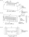
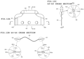
- Figs. 10A and 10B are diagrams illustrating another embodiment of the sipe blade 4.
- Fig. 11 is a plan view of the first blade 40 and the second blade 60.
- Figs. 12A to 12C are diagrams illustrating a relationship between the first blade 40 and the second blade 60.
- the sipe blade 4 extends so as to reach between the circumferential direction groove molding portions 10; 10, however, it is not limited thereto.
- the sipe blade 4 may be formed so as to extend in the tire width direction without reaching between the circumferential direction groove molding portions 10; 10. By configuring the sipe blade 4 in this manner, sipes that do not open in the circumferential direction groove may be formed on the tire.
- the sipe blade 4 according to Embodiment 5 is provided in such a manner that the second blade 60 comes in contact with the first blade 40. That is, in the above-described Embodiments 1 to 4, it has been explained that the second blade 60 is formed so as to support the molding surfaces 40m; 40m of the first blade 40 by the pair of groove walls 66m: 60m that form the accommodation groove 66. However, as illustrated in Figs 12A to 12C , the second blade 60 may be formed so that a step portion 72 is provided and one molding surface 40m of the first blade 40 comes in contact with the step portion 72.
- the step portion 72 is provided so as to extend along the outer periphery of the first blade 40 in such a manner as to extend from one end 62t of one of the strut portions 62 of the second blade 60 to one end 62t of the other one of the strut portions 62 via the coupling portion 64.
- the step portion 72 is formed in place of the accommodation groove 66 of Embodiments 1 to 4.
- the step portion 72 is provided with an abutment wall 72m against which the molding surface 40m of the first blade 40 abuts when the first blade 40 and the second blade are attached to the base mold 2, and an opposing wall 72n that opposes to the outer peripheral surface 40a of the first blade 40.
- the opposing wall 72n may be formed so as to have a predetermined gap relative to the outer peripheral surface 40a of the first blade 40.
- the opposing wall 72n By forming the opposing wall 72n so as to have the predetermined gap relative to the outer peripheral surface 40a of the first blade 40, the opposing wall 72n may be made movable with respect to the second blade 60 when an external force acts on the first blade 40. Namely, because it is possible to be displaced relative to the second blade 60 when the tire mold 1 is demolded from the tire, for example, occurrence of defects such as damaging the tire when demolding can be suppressed and the force acting on the first blade 40 can be released, it is possible to prevent unnecessary deformation of the first blade 40 and improve the durability of the sipe blade 4.
- the sipe blade 4 that molds one sipe (narrow groove) in the tire with two different materials, which are: the first blade 40 that is formed by pressing the metal plate; and the second blade 60 that is formed by the additive manufacturing method and that molds the wide groove in the sipe, it is also possible to maintain the durability of the sipe blade 4 while maintaining the degree of freedom of design in the sipe formation.
- the number of parts configuring the sipe blade 4 and the shape of the parts configuring the sipe blade 4 are not limited to those shown in each of the above-described Embodiments, and may be changed appropriately.
- the sipe blade 4 like the second blade 60
- by forming a part of the sipe blade by the additive manufacturing method it is possible to maintain the degree of freedom in setting the shape.
- a press-molded metal plate like the first blade 40, for the part where the strength is insufficient (the portion where the thickness is desired to be reduced) when formed by the additive manufacturing method, even in the case of molding a groove width of about 0.2 mm, for example, it is possible to prevent breakage at the time of demolding, and maintain the durability.
- the second blade 60 having a thickness greater than that of the first blade 40 is formed by the additive manufacturing method, however, it may be manufactured by precision casting or machining in a process different from forming of the base mold, for example.
- the vent passage 70 is provided in the second blade 60 and the vent hole 20 is provided in the base mold 2 so as to be communicated with the vent passage 70.
- the vent passage 70 is not provided in the second blade 60 (for example, like in Embodiment 1 and Embodiments 3 to 5)
- the first blade 40 is formed by pressing the plate member, and the second blade 60 is formed by the additive manufacturing method.
- the surface of the first blade 40 is smoother than the surface roughness (the visible roughness inherent to the additive manufacturing method) of the second blade 60 formed by the additive manufacturing method. Because a gap is formed between the first blade 40 and the second blade 60 due to this difference in the surface roughness, by utilizing this gap as a vent passage, air can be discharged from the vent hole 20 provided in the base mold 2.
- the gap formed by the difference in the surface roughness is such a degree to which rubber hardly enters, it has an advantage that molding marks such as spews are less likely to remain in the tire after molding.
- the manufacturing method of the tire mold is not limited to attaching the sipe blade 4 to the blade attachment portion 12 provided in the base mold 2, as described above.
- the sipe blade 4 may be embedded and integrated by casting in or the like, for example, when casting the base mold 2.
- a sipe blade which is implanted in a base mold and which molds a sipe in a tire is so configured that the sipe blade includes a first blade molded by pressing a plate member and a second blade having a thickness greater than a thickness of the first blade, in which the second blade is provided with a contact portion which extends along an outer periphery of the first blade implanted in the base mold and with which one molding surface of the first blade comes in contact along a peripheral edge portion of the first blade, or provided with a fitting portion which accommodates the peripheral edge portion of the first blade and with which both molding surfaces of the first blade come in contact.
- the second blade by providing the second blade with a groove that is communicated with the vent hole and extends along the contact portion where the first blade and the second blade come in contact or along the fitting portion, it is possible to discharge more of the air. It is also possible to further suppress the occurrence of spews during tire molding.
Landscapes
- Engineering & Computer Science (AREA)
- Mechanical Engineering (AREA)
- Moulds For Moulding Plastics Or The Like (AREA)
- Heating, Cooling, Or Curing Plastics Or The Like In General (AREA)
Abstract
Description
- The present invention relates to a sipe blade for forming sipes in a tire and a tire mold.
- Conventionally, in tires, by forming narrow grooves (so-called sipes), which have narrower widths than groove widths of main grooves, in tread blocks demarcated by the main grooves extending in the circumferential direction and in the width direction, a gripping force on ice is improved by controlling a block rigidity or increasing edges. Normally, a mold for molding such tires is manufactured by a casting process, however, if a part, which is used to mold such sipes as described above, especially sipes having a groove width of about 2 mm or less, is formed integrally with another part by casting in, there is a great danger of breakage of that part due to loads repeatedly applied at the time of tire molding and demolding. Thus, to cope with this, a thin member (a sipe blade) having been separately manufactured by press molding a metal plate or the like made of a steel material with higher strength, is casted in to the above-mentioned part.
- Patent Document 1:
Japanese Unexamined Patent Application Publication No. 2017-94539 - As described above, by press-molding the steel material of the sipe blade, a certain degree of freedom is obtained in setting of the shape of the sipe. On the other hand, since the sipe blade obtained by press-molding the steel material cannot be largely changed, in terms of the thickness thereof, there is a problem that the degree of freedom in changing the shape of the groove width, namely, partially widening the groove width of the sipe and so on, is low.
- It is therefore an object of the present invention to provide a sipe blade and a tire mold capable of improving the degree of freedom in setting the sipe shape in a tire while assuring a repeated fatigue life of the sipe blade.
- As a configuration of a sipe blade for solving the above-described problem, a sipe blade which is implanted in a base mold and which molds a sipe in a tire is configured to include a first blade molded by pressing a plate member and a second blade having a thickness greater than a thickness of the first blade, in which the second blade is provided with a contact portion which extends along an outer periphery of the first blade implanted in the base mold and with which one molding surface of the first blade comes in contact along a peripheral edge portion of the first blade, or provided with a fitting portion which accommodates the peripheral edge portion of the first blade and with which both molding surfaces of the first blade come in contact.
- Further, as a configuration of a tire mold for solving the above-described problem, a tire mold is provided with the sipe blade having the above-described configuration.
- It should be noted that the above-described summary of the invention does not enumerate all the necessary features of the present invention, and respective configurations constituting the feature groups can also be the invention.
-
-
Fig. 1 is a perspective view of a main part of a tire mold. -
Figs. 2A and 2B are a plan view and a cross-sectional view of a main part of a base mold. -
Figs. 3A to 3C are a plan view of a sipe blade and a plan view of a first blade. -
Figs. 4A to 4C are a plan view and a cross-sectional view of a second blade. -
Figs. 5A to 5C are an exploded perspective view and an assembly view of another sipe blade. -
Figs. 6A to 6C are diagrams illustrating another embodiment of the base mold. -
Figs. 7A to 7D are diagrams illustrating another embodiment of the sipe blade. -
Figs. 8A and 8B are diagrams illustrating another embodiment of the sipe blade. -
Figs. 9A to 9c are an exploded view and an assembly view of the sipe blade. -
Figs. 10A and 10B are diagrams illustrating another embodiment of the sipe blade. -
Fig. 11 is a plan view of the first blade and a plan view of the second blade. -
Figs. 12A to 12 C are diagrams illustrating a relationship between the first blade and the second blade. - Hereinafter, the present invention will be explained in detail through embodiments, however, the embodiments described below do not limit the inventions set forth in the claims, and not all of combinations of the features described in the embodiments are necessarily essential to the solving means of the invention.
-
Fig. 1 is a perspective view of a main part of a tire mold according toEmbodiment 1.Figs. 2A and 2B are a plan view and a cross-sectional view of a main part of a base mold. In the following description, directions are specified based on a direction of a tire to be molded by thetire mold 1, and described as a tire radial direction, a tire width direction and a tire circumferential direction, and a groove bottom side, a grounding surface side and so on with respect to the tire radial direction, the tire width direction and the tire circumferential direction. - As illustrated in
Fig. 1 , atire mold 1 according to the present embodiment is provided with abase mold 2 and asipe blade 4. Thetire mold 1 is manufactured by integrating thebase mold 2 and thesipe blade 4 respectively manufactured by separate processes. - As illustrated in
Figs. 1 and 2(A) and 2(B) , thebase mold 2 is a mold as a base into which thesipe blade 4 is implanted and is formed by, for example, casting, additive manufacturing method, machining and so on. In thebase mold 2, concaves and convexes for molding a molded item such as a tread block, and ablade attachment portion 12 for attaching thesipe blade 4, are formed on amolding surface 2a. The molded item is provided with convex portions, such as a plurality of circumferential direction groove moldingportions 10 for molding circumferential direction grooves as the molded item of the tire and a plurality of width direction groove molding portions (not shown in the figures) for molding width direction grooves. In the tire, circumferential direction grooves and width direction grooves are molded by the circumferential directiongroove molding portion 10 and the plurality of width direction groove molding portions, and tread blocks and so on demarcated by the circumferential direction grooves and the width direction grooves are molded. - The
blade attachment portion 12 extends along the tire width direction from one of the adjacent circumferential direction groove moldingportions groove molding portions blade attachment portion 12 is configured with a firstblade attachment portion 14 for attaching thefirst blade 40 and a secondblade attachment portion 16 for attaching thesecond blade 60. Thefirst blade 40 and thesecond blade 60 configure thesipe blade 4. - The first
blade attachment portion 14 is provided to linearly extend so as to connect between the circumferential directiongroove molding portions 10; 10. The firstblade attachment portion 14 is formed as a groove that is recessed in a slit shape into a groundingsurface molding portion 11, which molds a grounding surface of the tire, of themolding surface 2a of thebase mold 2. The firstblade attachment portion 14 is provided, along the tire width direction, with a plurality ofconvex portions 18 for fixing thefirst blade 40. Theconvex portion 18 is formed so as to swell in a spherical shape from agroove wall 14a forming the firstblade attachment portion 14. - The second
blade attachment portion 16 is provided in the circumferential directiongroove molding portion 10. The secondblade attachment portion 16 is recessed toward the outside in the tire width direction from a groovewall molding portion 10A, which forms the groove wall of the circumferential direction groove of the circumferential directiongroove molding portion 10 in the tire, extends in the tire radial direction from a groovebottom molding portion 10B, which forms the groove bottom of the circumferential direction groove of the circumferentialgroove molding portion 10 in the tire, and is formed as a concave portion recessed more than the groundingsurface molding portion 11 configuring themolding surface 2a. -
Figs. 3A and 3B are a plan view of thesipe blade 4 and a plan view of thefirst blade 40. As illustrated inFig. 1 andFig. 3A , thesipe blade 4 is provided with thefirst blade 40 and thesecond blade 60 and is attached to thebase mold 2 described above. Specifically, thefirst blade 40 is attached to the firstblade attachment portion 14 of theblade attachment portion 12 and thesecond blade 60 is attached to the secondblade attachment portion 16 of theblade attachment portion 12, respectively. By combining thefirst blade 40 and thesecond blade 60, one sipe is molded in the tire. - As illustrated in
Fig. 3B , thefirst blade 40 according to the present embodiment is formed in a one-side-long rectangular planar shape by machining such as pressing a metal plate having a predetermined thickness t1, for example. The thickness t1 of the metal plate is set so as to obtain a sipe of a desired groove width in the tire after molding. - The
first blade 40 is provided with a plurality of circular engagement holes 42 that penetrate in a plate thickness direction and that engages with theconvex portion 18 provided in the firstblade attachment portion 14. Thefirst blade 40 is attached to thebase mold 2 at a predetermined position in such a manner as not to fall off by engaging theengagement hole 42 with theconvex portion 18 provided in the firstblade attachment portion 14. -
Figs. 4A to 4C are a plan view and a cross-sectional view of thesecond blade 60. As illustrated inFig. 4A , thesecond blade 60 is provided withstrut portions 62; 62 extending along a pair of short sides facing each other in thefirst blade 40 and acoupling portion 64 which extends along one long side of thefirst blade 40 and couples thestrut portions 62; 62. Thesecond blade 60 is formed, for example, by the additive manufacturing method which is different from the manufacturing method used for thefirst blade 40. The thickness t2 of thesecond blade 60 is set to be greater than the thickness t1 of thefirst blade 40. The thickness t2 of thesecond blade 60 refers to all of thestrut portions 62; 62 and thecoupling portion 64 that configure thesecond blade 60. - The
strut portions blade attachment portions base mold 2, respectively, and, as illustrated inFig. 1 , are formed to have an outer shape that is integral with the circumferential directiongroove molding portions 10; 10 in thebase mold 2. Thecoupling portion 64 is bridged across thestrut portions 62; 62 so as to extend a position shallower than the groove bottom formed in the tire by the circumferential directiongroove molding portions 10; 10. As illustrated inFig. 4C , thecoupling portion 64 is formed in a teardrop shape, one side of which is tapered off in a cross-sectional view orthogonal to the extension direction. - As illustrated in
Figs. 4A and 4B , thesecond blade 60 is provided with anaccommodation groove 66 that extends continuously from onestrut portion 62 through thecoupling portion 64 to theother strut portion 62 and that accommodate a pair of short sides and a long side of thefirst blade 40. Theaccommodation groove 66 functions as a fitting portion into which the outer peripheral portion of thefirst blade 40 is fitted. - The
accommodation groove 66 is configured withstrut portion grooves 67; 67 formed in thestrut portion 62 and acoupling portion groove 68 formed in thecoupling portion 64. Thestrut portion grooves 67; 67 formed in each of thestrut portions 62; 62 face each other and extend parallel to each other from oneend 62t in the extension direction of each of thestrut portions 62; 62 to thecoupling portion 64 along the extension direction of thestrut portion 62. Thecoupling portion groove 68 extends along the extension direction of thecoupling portion 64 and is connected to thestrut portion grooves 67; 67 provided in each of thestrut portions 62; 62. - The groove width L3 of the
accommodation groove 66 is so formed that the short sides of thefirst blade 40 can be inserted from oneend 62t; 62t sides of thestrut portion grooves 67; 67 in a manner that thefirst blade 40 can be slidable toward thecoupling portion 64, and that one long side of thefirst blade 40 can be inserted into thecoupling portion groove 68. In other words, by fitting thefirst blade 40 into theaccommodation groove 66 of thesecond blade 60, thefirst blade 40 and thesecond blade 60 are integrated as onesipe blade 4. - Hereinafter, an explanation is given as to the relationship between the
second blade 60 and thefirst blade 40 when thesecond blade 60 and thefirst blade 40 are integrated. - As illustrated in the enlarged views of
Figs. 4B and 4C , for example, thestrut portion grooves 67; 67 and thecoupling portion groove 68 are each formed into a box shape opening at one end thereof as seen in the cross-sectional view orthogonal to the extension direction. As illustrated inFig. 4B , the length L2 betweengroove bottoms 67n; 67n of the opposingstrut portion grooves 67; 67 provided in therespective strut portions 62 of thesecond blade 60 is set slightly longer than the length L1 of the long side of thefirst blade 40, and the groove width L3, which is the distance betweengroove walls 67m; 67m of thestrut portion grooves first blade 40. As such, the dimensions are set so as to have the gap that allows the sliding as described above. - As illustrated in
Fig. 4C , with respect to thesecond blade 60, the groove width L3, which is the distance betweengroove walls 68m; 68m forming thecoupling portion groove 68, is set slightly wider than the thickness t1 of thefirst blade 40. Further, the distance L4 from oneend 62t to thegroove bottom 68n is so set that, when the outer peripheral surface (plate thickness portion) 40a of one long side of thefirst blade 40 reaches thegroove bottom 68n of thecoupling portion groove 68 of thesecond blade 60, the outerperipheral surface 40a of the other long side (long side not accommodated in the coupling portion groove 68) becomes flush with oneend 62t of thestrut portion 62. - As described above, the
sipe blade 4 is inserted into theblade attachment portion 12 of thebase mold 2, for example, in the state in which thefirst blade 40 is combined with thesecond blade 60, and configures a part of thetire mold 1. In the state of being attached to thebase mold 2, thesipe blade 4 can change the groove width, in the tire radial direction, of one sipe when the tire is molded, as thefirst blade 40 and thecoupling portion 64 of thesecond blade 60, which have different thicknesses, are exposed between the circumferential directiongroove molding portions 10; 10. - In this way, namely, it is possible to mold a narrow groove extending in the tire radial direction from the grounding surface of the tire by the
first blade 40 which is thin in the thickness, and mold a wide groove having a wide groove width by thesecond blade 60 which is greater in the thickness than that of thefirst blade 40 on the groove bottom side of this narrow groove. By molding the sipe in this manner, water entering into the narrow groove from the grounding surface side can be efficiently drained from the wide groove on the groove bottom side to the circumferential direction groove. - In this way, by using a member, which is formed by pressing a plate member, for the portion of the sipe where the narrow groove is molded, and by forming, by the additive manufacturing method, the portion where the wide groove is molded, advantages of each manufacturing method can be utilized and the durability of the
sipe blade 4 can be improved. In other words, if the sipe blade for molding the narrow groove is formed by the additive manufacturing method, the durability is degraded, however, this can be prevented by using a plate member. -
Figs. 5A to 5C are diagrams illustrating another embodiment of thesipe blade 4.Figs. 6A to 6C are diagrams illustrating another embodiment of thebase mold 2. With respect to the above-describedEmbodiment 1, it has been described that the outer periphery of thefirst blade 40 is fitted into theaccommodation groove 66 of thesecond blade 60. However, as illustrated inFigs. 5A to 5C , avent passage 70 that makes it possible to ventilate air may be provided in theaccommodation groove 66. Hereinafter, another embodiment of thesipe blade 4 will be explained usingFigs. 5A to 5C and6A to 6C . As described above, thesecond blade 60 can be easily manufactured using the additive manufacturing method. - The
sipe blade 4 according to the present embodiment differs from theaforementioned sipe blade 4 in that thesipe blade 4 according to the present embodiment is provided with thevent passage 70 that makes it possible to exhaust air intervening between thetire mold 1 and a green tire during tire molding. As illustrated inFigs. 5A and 5B , thevent passage 70 extends along theaccommodation groove 66 so as to form the groove bottom of theaccommodation groove 66 that continuously extends from onestrut portion 62 of thesecond blade 60 through thecoupling portion 64 to theother strut portion 62. - Since the
accommodation groove 66 is formed by the additive manufacturing method and thefirst blade 40 is formed by pressing the plate member, the surface roughness differs from each other. More specifically, the surface of thefirst blade 40 is smoother than the surface roughness (the visible roughness inherent to the additive manufacturing method) of thesecond blade 60 formed by the additive manufacturing method. Due to this difference in the surface roughness, a gap is formed between thefirst blade 40 and thesecond blade 60, which allows air to flow into thevent passage 70. This gap may be utilized as an introduction path to thevent passage 70. - In the case of configuring the
sipe blade 4 in this manner, as illustrated inFigs. 6A to 6C , it is desirable to provide, in thebase mold 2, vent holes 20 that penetrate to the secondblade attachment portion 16 to which thestrut portions 62; 62 of thesecond blade 60 are attached, and to theback surface 2b of thebase mold 2. By configuring thebase mold 2 in this manner, air intervening between the green tire and themolding surface 2a can be efficiently discharged when molding the tire, thus it is unnecessary to provide the vent hole in another part of thebase mold 2. In addition, with this configuration, air can be discharged from thevent hole 20 provided in thebase mold 2. Further, because the gap formed by the difference in the surface roughness is such a degree to which rubber hardly enters, not only the air can be discharged through thesipe blade 4, but also spews (molding mark) are not molded on the surface of the tire. Thus, the appearance of the tire after molding can be improved. -
Figs. 7A to 7D are diagrams illustrating another embodiment of thesipe blade 4. In the above-describedEmbodiments first blade 40 is a one-side-long flat rectangle plate, it is not limited thereto. As illustrated inFigs. 7A and 7B , thefirst blade 40 may be formed to be a so-called 3D sipe having concaves and convexes in the tire circumferential direction and in the tire radial direction. - The
second blade 60 may be formed by the additive manufacturing method to have thesupport portions 62; 62 and thecoupling portion 64 as separate members, as illustrated inFig. 7B , without integrating thesupport portions 62; 62 and thecoupling portion 64 unlike in the above-describedEmbodiments Fig. 7C , it is desirable to form, in eachstrut portion 62, astrut portion groove 67 into which the short side of thefirst blade 40 is inserted, and a coupling portion insertion concave portion 69 into which the end portion of thecoupling portion 64 can be inserted. Furthermore, as illustrated inFig. 7D , thebase mold 2 may be formed with a firstblade attachment portion 14 in correspondence to concaves and convexes formed in thefirst blade 40. -
Figs. 8A and 8B are diagrams illustrating another embodiment of thesipe blade 4.Figs. 9A to 9C are an exploded view and an assembly view of thesipe blade 4. Thefirst blade 40 configuring thesipe blade 4 is not limited to onefirst blade 40 as shown in the above-describedEmbodiments 1 to 3, but, as illustrated inFigs. 8A and 8B and Figs. 9B and 9C , may be configured by a plurality offirst blades 40A to 40C. As illustrated inFig. 8B , thefirst blades 40A to 40C are arranged so that thesipe blade 4 takes an arc shape. Namely, thesipe blade 4 shown inEmbodiment 4 extends in the arc shape between the circumferential directiongroove molding portions 10; 10. - As illustrated in
Figs. 9A to 9C , thesecond blade 60 is provided to be put on thefirst blades 40A to 40C attached to thebase mold 2, and is integrated with thefirst blades 40A to 40C as thesipe blade 4. Thesecond blade 60 is attached to thefirst blades 40A to 40 C exposed from thebase mold 2, and to thebase mold 2 from the standing direction of thefirst blades 40A to 40C. Thesecond blade 60 is provided with a plurality ofopenings 61A; 61B; 61C for, when attached to thebase mold 2, exposing the molding surfaces 40m; 40m of thefirst blades 40A to 40C attached to thebase mold 2 while surrounding the outer periphery of thefirst blades 40A to 40C. - As illustrated in
Fig. 9A , thesecond blade 60 is formed with astrut portion 62 A that rises up between one of the circumferentialgroove molding portions 10 and thefirst blade 40A, astrut portion 62B that rises up between thefirst blades strut portion 62 C that rises up between thefirst blades strut portion 62D that rises up between thefirst blade 40C and the other one of the circumferential groove moldedportions 10, and thecoupling portion 64 that connects tip ends of thestrut portions 62A to 62D rising up from thebase mold 2. In this embodiment, thesecond blade 60 is formed so as not to be included in the circumferential directiongroove molding portions 10; 10. That is, thesecond blade 60 is formed so that thestrut portions wall molding portions 10A of the circumferentialgroove molding portions 10; 10. - In the
second blade 60, groove-shaped accommodation grooves (corresponding to the above-described accommodation groove 66) extending along the extension direction of theplate thickness surface 61m and into which the outer peripheries of thefirst blades 40A to 40C can be inserted, are formed in theplate thickness surface 61m forming theopenings 61A; 61B; 61C. Thesipe blade 4 may be formed as shown in thisEmbodiment 4. - Incidentally, it should be noted that the thicknesses of the
first blades 40A to 40C may be set appropriately, namely, may be set to be the same or may be set to be different for each blade or may be set such that two of the first blades may be set to have the same thickness and the remaining one may be set to have a different thickness. Even when the thicknesses of thefirst blades 40A to 40C are changed as described above, by forming thesecond blade 60 by the additive manufacturing method, it is possible to easily change the groove width for accommodating thefirst blades 40A to 40C and form the groove. -
Figs. 10A and 10B are diagrams illustrating another embodiment of thesipe blade 4.Fig. 11 is a plan view of thefirst blade 40 and thesecond blade 60.Figs. 12A to 12C are diagrams illustrating a relationship between thefirst blade 40 and thesecond blade 60. - In the above-described
Embodiments 1 to 4, it has been explained that thesipe blade 4 extends so as to reach between the circumferential directiongroove molding portions 10; 10, however, it is not limited thereto. As illustrated inFigs. 10A and 10B , thesipe blade 4 may be formed so as to extend in the tire width direction without reaching between the circumferential directiongroove molding portions 10; 10. By configuring thesipe blade 4 in this manner, sipes that do not open in the circumferential direction groove may be formed on the tire. - The
sipe blade 4 according to Embodiment 5 is provided in such a manner that thesecond blade 60 comes in contact with thefirst blade 40. That is, in the above-describedEmbodiments 1 to 4, it has been explained that thesecond blade 60 is formed so as to support the molding surfaces 40m; 40m of thefirst blade 40 by the pair of groove walls 66m: 60m that form theaccommodation groove 66. However, as illustrated inFigs 12A to 12C , thesecond blade 60 may be formed so that astep portion 72 is provided and onemolding surface 40m of thefirst blade 40 comes in contact with thestep portion 72. - As illustrated in
Fig. 11 , for example, thestep portion 72 is provided so as to extend along the outer periphery of thefirst blade 40 in such a manner as to extend from oneend 62t of one of thestrut portions 62 of thesecond blade 60 to oneend 62t of the other one of thestrut portions 62 via thecoupling portion 64. In other words, thestep portion 72 is formed in place of theaccommodation groove 66 ofEmbodiments 1 to 4. Thestep portion 72 is provided with anabutment wall 72m against which themolding surface 40m of thefirst blade 40 abuts when thefirst blade 40 and the second blade are attached to thebase mold 2, and an opposingwall 72n that opposes to the outerperipheral surface 40a of thefirst blade 40. The opposingwall 72n may be formed so as to have a predetermined gap relative to the outerperipheral surface 40a of thefirst blade 40. - By forming the opposing
wall 72n so as to have the predetermined gap relative to the outerperipheral surface 40a of thefirst blade 40, the opposingwall 72n may be made movable with respect to thesecond blade 60 when an external force acts on thefirst blade 40. Namely, because it is possible to be displaced relative to thesecond blade 60 when thetire mold 1 is demolded from the tire, for example, occurrence of defects such as damaging the tire when demolding can be suppressed and the force acting on thefirst blade 40 can be released, it is possible to prevent unnecessary deformation of thefirst blade 40 and improve the durability of thesipe blade 4. - In the case of setting different thicknesses to the
sipe blade 4, by combining thefirst blade 40 and thesecond blade 60 that are different in the thickness to form onesipe blade 4 for molding the tire, and by molding the narrow groove in the tire by thefirst blade 40 and by molding a groove, having a wide groove width, on the groove bottom side of the sipe by thesecond blade 60 having the thickness greater than that of thefirst blade 40, it is possible to improve, while gaining an edge effect on ice and snow by the portion molded by thefirst blade 40, the performance of drainage of water entered into the groove by the portion molded by thesecond blade 60. - As explained above using each of
Embodiments 1 to 5, by configuring thesipe blade 4 that molds one sipe (narrow groove) in the tire, with two different materials, which are: thefirst blade 40 that is formed by pressing the metal plate; and thesecond blade 60 that is formed by the additive manufacturing method and that molds the wide groove in the sipe, it is also possible to maintain the durability of thesipe blade 4 while maintaining the degree of freedom of design in the sipe formation. - It should be noted that the number of parts configuring the
sipe blade 4 and the shape of the parts configuring thesipe blade 4 are not limited to those shown in each of the above-described Embodiments, and may be changed appropriately. - For example, in setting the
sipe blade 4, like thesecond blade 60, by forming a part of the sipe blade by the additive manufacturing method, it is possible to maintain the degree of freedom in setting the shape. In addition, by utilizing a press-molded metal plate, like thefirst blade 40, for the part where the strength is insufficient (the portion where the thickness is desired to be reduced) when formed by the additive manufacturing method, even in the case of molding a groove width of about 0.2 mm, for example, it is possible to prevent breakage at the time of demolding, and maintain the durability. - In other words, it is possible to provide a durable sipe blade and a tire mold while utilizing the superiority of the degree of freedom in forming the sipe on the tire by the additive manufacturing method.
- Incidentally, in the above description, it has been explained that the
second blade 60 having a thickness greater than that of thefirst blade 40 is formed by the additive manufacturing method, however, it may be manufactured by precision casting or machining in a process different from forming of the base mold, for example. - Further, it has been explained that, in
Embodiment 2, thevent passage 70 is provided in thesecond blade 60 and thevent hole 20 is provided in thebase mold 2 so as to be communicated with thevent passage 70. However, in a case in which thevent passage 70 is not provided in the second blade 60 (for example, like inEmbodiment 1 andEmbodiments 3 to 5), it is desirable to provide thevent hole 20 in thebase mold 2 in such a manner that thevent hole 20 opens to theaccommodation groove 66 opened at oneend 62t of eachstrut portion 62 of thesecond blade 60 attached to thebase mold 2. As described above, thefirst blade 40 is formed by pressing the plate member, and thesecond blade 60 is formed by the additive manufacturing method. For this reason, the surface of thefirst blade 40 is smoother than the surface roughness (the visible roughness inherent to the additive manufacturing method) of thesecond blade 60 formed by the additive manufacturing method. Because a gap is formed between thefirst blade 40 and thesecond blade 60 due to this difference in the surface roughness, by utilizing this gap as a vent passage, air can be discharged from thevent hole 20 provided in thebase mold 2. In addition, since the gap formed by the difference in the surface roughness is such a degree to which rubber hardly enters, it has an advantage that molding marks such as spews are less likely to remain in the tire after molding. - It should be noted that the manufacturing method of the tire mold is not limited to attaching the
sipe blade 4 to theblade attachment portion 12 provided in thebase mold 2, as described above. Thesipe blade 4 may be embedded and integrated by casting in or the like, for example, when casting thebase mold 2. - As explained above, a sipe blade which is implanted in a base mold and which molds a sipe in a tire is so configured that the sipe blade includes a first blade molded by pressing a plate member and a second blade having a thickness greater than a thickness of the first blade, in which the second blade is provided with a contact portion which extends along an outer periphery of the first blade implanted in the base mold and with which one molding surface of the first blade comes in contact along a peripheral edge portion of the first blade, or provided with a fitting portion which accommodates the peripheral edge portion of the first blade and with which both molding surfaces of the first blade come in contact. With this configuration, it is possible to improve the degree of freedom in setting of the sipe shape and, even for the sipe blade having a special shape, it is possible to manufacture the sipe blade with a repetitive fatigue life without a practical problem.
- Further, by configuring such that a part of the second blade is included in a part of the molded item to be molded in the tire by the base mold, it is possible to improve the durability due to the undercut shape caused by a 3D bent shape of the sipe blade.
- Further, by configuring such that a gap, which is generated in the contact portion where the first blade and the second blade come in contact or which is generated in the fitting portion, is communicated with the vent hole provided in the base mold, air can be discharged through the gap generated in the contact portion or in the fitting portion of the second blade. Therefore, it is unnecessary to provide the vent hole separately at another position of the
base mold 2, and it is possible to suppress the occurrence of spews during tire molding. - Further, by providing the second blade with a groove that is communicated with the vent hole and extends along the contact portion where the first blade and the second blade come in contact or along the fitting portion, it is possible to discharge more of the air. It is also possible to further suppress the occurrence of spews during tire molding.
- Further, by configuring such that a tire mold is provided with the sipe blade according to any of
claims 1 to 6, the durability of the tire mold can be improved. -
- 1: Tire mold, 2: Base mold, 4: Sipe blade,
- 20: Vent hole, 40: First blade, 60: Second blade, 66: Accommodation groove, 70: Vent passage.
Claims (5)
- A sipe blade which is implanted in a base mold and which molds a sipe in a tire, comprising:a first blade molded by pressing a plate member; anda second blade having a thickness greater than a thickness of the first blade,wherein the second blade is provided with:a contact portion which extends along an outer periphery of the first blade implanted in the base mold and with which one molding surface of the first blade comes in contact along a peripheral edge portion of the first blade, ora fitting portion which accommodates the peripheral edge portion of the first blade and with which both molding surfaces of the first blade come in contact.
- The sipe blade according to claim 1, wherein a part of the second blade is included in a part of a molded item to be molded in the tire by the base mold.
- The sipe blade according to claim 1 or 2, wherein a gap, which is generated in the contact portion where the first blade and the second blade come in contact or which is generated in the fitting portion, is communicated with a vent hole provided in the base mold.
- The sipe blade according to claim 3, wherein the second blade is provided with a groove which is communicated with the vent hole and extends along the contact portion where the first blade and the second blade come in contact or along the fitting portion.
- A tire mold comprising the sipe blade according to any one of claims 1 to 4.
Applications Claiming Priority (2)
| Application Number | Priority Date | Filing Date | Title |
|---|---|---|---|
| JP2021010847A JP7553370B2 (en) | 2021-01-27 | 2021-01-27 | Sipe blades and tire molds |
| PCT/JP2021/041149 WO2022163060A1 (en) | 2021-01-27 | 2021-11-09 | Sipe blade and tire mold |
Publications (2)
| Publication Number | Publication Date |
|---|---|
| EP4286148A1 true EP4286148A1 (en) | 2023-12-06 |
| EP4286148A4 EP4286148A4 (en) | 2024-07-03 |
Family
ID=82653130
Family Applications (1)
| Application Number | Title | Priority Date | Filing Date |
|---|---|---|---|
| EP21923065.3A Pending EP4286148A4 (en) | 2021-01-27 | 2021-11-09 | Sipe blade and tire mold |
Country Status (5)
| Country | Link |
|---|---|
| US (1) | US20240066822A1 (en) |
| EP (1) | EP4286148A4 (en) |
| JP (1) | JP7553370B2 (en) |
| CN (1) | CN116745086A (en) |
| WO (1) | WO2022163060A1 (en) |
Family Cites Families (7)
| Publication number | Priority date | Publication date | Assignee | Title |
|---|---|---|---|---|
| JPH04353432A (en) * | 1991-05-31 | 1992-12-08 | Toyo Tire & Rubber Co Ltd | Sipe blade for forming pneumatic tire and metal die |
| JP2000102925A (en) | 1998-09-28 | 2000-04-11 | Ngk Fine Mold Kk | Sipe forming skeleton and production of tire mold |
| KR100551880B1 (en) * | 2004-07-01 | 2006-02-13 | 한국타이어 주식회사 | Blade of the vulcanizing mold for making kerf |
| CN102245405A (en) * | 2008-12-31 | 2011-11-16 | 米其林技术公司 | System for changing sipe blades for molding or retreading tires |
| JP2014151518A (en) | 2013-02-07 | 2014-08-25 | Sumitomo Rubber Ind Ltd | Mold for tire |
| JP6600537B2 (en) | 2015-11-19 | 2019-10-30 | 株式会社ブリヂストン | Tire vulcanization mold and manufacturing method thereof |
| FR3053918A1 (en) | 2016-07-18 | 2018-01-19 | Compagnie Generale Des Etablissements Michelin | EVOLUTIVE SLIDER FOR FITTING A MOLD FOR VULCANIZING A PNEUMATIC |
-
2021
- 2021-01-27 JP JP2021010847A patent/JP7553370B2/en active Active
- 2021-11-09 US US18/271,267 patent/US20240066822A1/en active Pending
- 2021-11-09 EP EP21923065.3A patent/EP4286148A4/en active Pending
- 2021-11-09 WO PCT/JP2021/041149 patent/WO2022163060A1/en active Application Filing
- 2021-11-09 CN CN202180092136.8A patent/CN116745086A/en active Pending
Also Published As
| Publication number | Publication date |
|---|---|
| US20240066822A1 (en) | 2024-02-29 |
| JP7553370B2 (en) | 2024-09-18 |
| JP2022114546A (en) | 2022-08-08 |
| CN116745086A (en) | 2023-09-12 |
| EP4286148A4 (en) | 2024-07-03 |
| WO2022163060A1 (en) | 2022-08-04 |
Similar Documents
| Publication | Publication Date | Title |
|---|---|---|
| US8506275B2 (en) | Removable device for moulding a flexible wall in the groove of a tire pattern | |
| CN107708980B (en) | Set of moulding elements and mould | |
| US6416304B1 (en) | Mold for molding tire | |
| CN103946002B (en) | Comprise the mould of the cavity for locking device molded in groove | |
| CN110382217B (en) | Assembly of moulding elements for a tyre mould | |
| JP2015501739A (en) | Mold with cavity for molding device for closure in groove | |
| EP4286148A1 (en) | Sipe blade and tire mold | |
| JPH10236112A (en) | Pneumatic tire and vulcanizing mold used for manufacturing it | |
| KR101414100B1 (en) | Mold for tire | |
| US8834143B2 (en) | Tire vulcanization mold | |
| EP3441240A1 (en) | Tire mold and tire | |
| CN108367522B (en) | Sipe elements for inner liner tire molds and related methods of manufacture | |
| CN109476103B (en) | Variant sheet of a mold insert intended for tire vulcanization | |
| EP4249226A1 (en) | Sipe blade, tire molding mold, and tire manufacturing method | |
| US10427372B2 (en) | Tire vulcanizing die, casting die for casting tire vulcanizing die, and method for manufacturing tire vulcanizing die | |
| CN109195765B (en) | Moulding element for manufacturing a noise-reducing tread | |
| US11247366B2 (en) | Molding element for manufacturing a noise reducing tread | |
| CN113557117B (en) | Method for manufacturing mold for tire molding | |
| JP7210942B2 (en) | Tire vulcanization mold and tire | |
| CN112238552B (en) | Method for manufacturing mold for tire, method for manufacturing tire, and mold for tire | |
| JP2005131685A (en) | Method for producing metallic mold for tire and sipe forming edge used for this method | |
| CN112055640B (en) | Molding element with venting grooves and micromolding | |
| KR101687387B1 (en) | A vacuum pump for a vechicle comprising a slider and a mold for manufacturing the slider for mounting to a vane of the vacuum pump | |
| KR100329996B1 (en) | Tire mold for easy venting on the side-wall | |
| CN112974728A (en) | Method for manufacturing mold, method for manufacturing tire, and mold for tire |
Legal Events
| Date | Code | Title | Description |
|---|---|---|---|
| STAA | Information on the status of an ep patent application or granted ep patent |
Free format text: STATUS: THE INTERNATIONAL PUBLICATION HAS BEEN MADE |
|
| PUAI | Public reference made under article 153(3) epc to a published international application that has entered the european phase |
Free format text: ORIGINAL CODE: 0009012 |
|
| STAA | Information on the status of an ep patent application or granted ep patent |
Free format text: STATUS: REQUEST FOR EXAMINATION WAS MADE |
|
| 17P | Request for examination filed |
Effective date: 20230704 |
|
| AK | Designated contracting states |
Kind code of ref document: A1 Designated state(s): AL AT BE BG CH CY CZ DE DK EE ES FI FR GB GR HR HU IE IS IT LI LT LU LV MC MK MT NL NO PL PT RO RS SE SI SK SM TR |
|
| DAV | Request for validation of the european patent (deleted) | ||
| DAX | Request for extension of the european patent (deleted) | ||
| REG | Reference to a national code |
Ref country code: DE Ref legal event code: R079 Free format text: PREVIOUS MAIN CLASS: B29L0030000000 Ipc: B29D0030060000 |
|
| A4 | Supplementary search report drawn up and despatched |
Effective date: 20240603 |
|
| RIC1 | Information provided on ipc code assigned before grant |
Ipc: B29L 30/00 20060101ALI20240527BHEP Ipc: B29C 33/42 20060101ALI20240527BHEP Ipc: B29C 35/02 20060101ALI20240527BHEP Ipc: B29C 33/02 20060101ALI20240527BHEP Ipc: B29D 30/06 20060101AFI20240527BHEP |