EP4286147A2 - Sole structure for article of footwear - Google Patents
Sole structure for article of footwear Download PDFInfo
- Publication number
- EP4286147A2 EP4286147A2 EP23202986.8A EP23202986A EP4286147A2 EP 4286147 A2 EP4286147 A2 EP 4286147A2 EP 23202986 A EP23202986 A EP 23202986A EP 4286147 A2 EP4286147 A2 EP 4286147A2
- Authority
- EP
- European Patent Office
- Prior art keywords
- fluid
- sole structure
- segment
- filled segment
- bladder
- Prior art date
- Legal status (The legal status is an assumption and is not a legal conclusion. Google has not performed a legal analysis and makes no representation as to the accuracy of the status listed.)
- Pending
Links
- 239000012530 fluid Substances 0.000 claims abstract description 206
- 230000008878 coupling Effects 0.000 claims abstract description 4
- 238000010168 coupling process Methods 0.000 claims abstract description 4
- 238000005859 coupling reaction Methods 0.000 claims abstract description 4
- 229920000642 polymer Polymers 0.000 claims description 23
- 210000004744 fore-foot Anatomy 0.000 claims description 21
- 239000006261 foam material Substances 0.000 claims description 3
- 230000004888 barrier function Effects 0.000 description 126
- 239000010410 layer Substances 0.000 description 103
- 239000000463 material Substances 0.000 description 40
- 210000002683 foot Anatomy 0.000 description 20
- 210000000474 heel Anatomy 0.000 description 17
- 230000002093 peripheral effect Effects 0.000 description 17
- 229920001577 copolymer Polymers 0.000 description 13
- 239000011800 void material Substances 0.000 description 12
- 239000004433 Thermoplastic polyurethane Substances 0.000 description 11
- 229920002803 thermoplastic polyurethane Polymers 0.000 description 11
- 239000007789 gas Substances 0.000 description 10
- -1 polysiloxane Polymers 0.000 description 10
- 239000006260 foam Substances 0.000 description 9
- 238000000034 method Methods 0.000 description 9
- 229920001971 elastomer Polymers 0.000 description 8
- 229920002635 polyurethane Polymers 0.000 description 8
- 239000004814 polyurethane Substances 0.000 description 8
- 230000005540 biological transmission Effects 0.000 description 6
- 238000000465 moulding Methods 0.000 description 6
- 239000013518 molded foam Substances 0.000 description 5
- 230000008569 process Effects 0.000 description 5
- 239000005060 rubber Substances 0.000 description 5
- IJGRMHOSHXDMSA-UHFFFAOYSA-N Atomic nitrogen Chemical compound N#N IJGRMHOSHXDMSA-UHFFFAOYSA-N 0.000 description 4
- 239000011324 bead Substances 0.000 description 4
- 230000006835 compression Effects 0.000 description 4
- 238000007906 compression Methods 0.000 description 4
- 239000004715 ethylene vinyl alcohol Substances 0.000 description 4
- 238000001746 injection moulding Methods 0.000 description 4
- 239000000203 mixture Substances 0.000 description 4
- 229920001169 thermoplastic Polymers 0.000 description 4
- DVKJHBMWWAPEIU-UHFFFAOYSA-N toluene 2,4-diisocyanate Chemical compound CC1=CC=C(N=C=O)C=C1N=C=O DVKJHBMWWAPEIU-UHFFFAOYSA-N 0.000 description 4
- UPMLOUAZCHDJJD-UHFFFAOYSA-N 4,4'-Diphenylmethane Diisocyanate Chemical compound C1=CC(N=C=O)=CC=C1CC1=CC=C(N=C=O)C=C1 UPMLOUAZCHDJJD-UHFFFAOYSA-N 0.000 description 3
- 229920000219 Ethylene vinyl alcohol Polymers 0.000 description 3
- 229920001400 block copolymer Polymers 0.000 description 3
- 239000002666 chemical blowing agent Substances 0.000 description 3
- 229910001873 dinitrogen Inorganic materials 0.000 description 3
- 239000000806 elastomer Substances 0.000 description 3
- RZXDTJIXPSCHCI-UHFFFAOYSA-N hexa-1,5-diene-2,5-diol Chemical compound OC(=C)CCC(O)=C RZXDTJIXPSCHCI-UHFFFAOYSA-N 0.000 description 3
- 239000012948 isocyanate Substances 0.000 description 3
- 150000002513 isocyanates Chemical class 0.000 description 3
- 210000000452 mid-foot Anatomy 0.000 description 3
- 230000004043 responsiveness Effects 0.000 description 3
- 239000002356 single layer Substances 0.000 description 3
- 229920006132 styrene block copolymer Polymers 0.000 description 3
- 238000003856 thermoforming Methods 0.000 description 3
- 239000004416 thermosoftening plastic Substances 0.000 description 3
- NNOZGCICXAYKLW-UHFFFAOYSA-N 1,2-bis(2-isocyanatopropan-2-yl)benzene Chemical compound O=C=NC(C)(C)C1=CC=CC=C1C(C)(C)N=C=O NNOZGCICXAYKLW-UHFFFAOYSA-N 0.000 description 2
- ALQLPWJFHRMHIU-UHFFFAOYSA-N 1,4-diisocyanatobenzene Chemical compound O=C=NC1=CC=C(N=C=O)C=C1 ALQLPWJFHRMHIU-UHFFFAOYSA-N 0.000 description 2
- SBJCUZQNHOLYMD-UHFFFAOYSA-N 1,5-Naphthalene diisocyanate Chemical compound C1=CC=C2C(N=C=O)=CC=CC2=C1N=C=O SBJCUZQNHOLYMD-UHFFFAOYSA-N 0.000 description 2
- YEBSYMIZFYCPRG-UHFFFAOYSA-N 3-(oxomethylidene)penta-1,4-diene-1,5-dione Chemical compound O=C=CC(=C=O)C=C=O YEBSYMIZFYCPRG-UHFFFAOYSA-N 0.000 description 2
- 239000004604 Blowing Agent Substances 0.000 description 2
- KAKZBPTYRLMSJV-UHFFFAOYSA-N Butadiene Chemical compound C=CC=C KAKZBPTYRLMSJV-UHFFFAOYSA-N 0.000 description 2
- VTYYLEPIZMXCLO-UHFFFAOYSA-L Calcium carbonate Chemical compound [Ca+2].[O-]C([O-])=O VTYYLEPIZMXCLO-UHFFFAOYSA-L 0.000 description 2
- RTZKZFJDLAIYFH-UHFFFAOYSA-N Diethyl ether Chemical group CCOCC RTZKZFJDLAIYFH-UHFFFAOYSA-N 0.000 description 2
- RRHGJUQNOFWUDK-UHFFFAOYSA-N Isoprene Chemical compound CC(=C)C=C RRHGJUQNOFWUDK-UHFFFAOYSA-N 0.000 description 2
- 239000004952 Polyamide Substances 0.000 description 2
- 239000004721 Polyphenylene oxide Substances 0.000 description 2
- VYPSYNLAJGMNEJ-UHFFFAOYSA-N Silicium dioxide Chemical compound O=[Si]=O VYPSYNLAJGMNEJ-UHFFFAOYSA-N 0.000 description 2
- 229920002125 Sokalan® Polymers 0.000 description 2
- 210000003423 ankle Anatomy 0.000 description 2
- 125000003118 aryl group Chemical group 0.000 description 2
- 238000005266 casting Methods 0.000 description 2
- 238000006243 chemical reaction Methods 0.000 description 2
- 238000000748 compression moulding Methods 0.000 description 2
- 239000003431 cross linking reagent Substances 0.000 description 2
- 239000013536 elastomeric material Substances 0.000 description 2
- 150000002148 esters Chemical group 0.000 description 2
- 238000001125 extrusion Methods 0.000 description 2
- 239000000945 filler Substances 0.000 description 2
- 238000005187 foaming Methods 0.000 description 2
- 229920001519 homopolymer Polymers 0.000 description 2
- 239000002245 particle Substances 0.000 description 2
- 150000002978 peroxides Chemical class 0.000 description 2
- 239000004584 polyacrylic acid Substances 0.000 description 2
- 229920002239 polyacrylonitrile Polymers 0.000 description 2
- 229920002647 polyamide Polymers 0.000 description 2
- 229920000570 polyether Polymers 0.000 description 2
- 229920002725 thermoplastic elastomer Polymers 0.000 description 2
- JOYRKODLDBILNP-UHFFFAOYSA-N urethane group Chemical group NC(=O)OCC JOYRKODLDBILNP-UHFFFAOYSA-N 0.000 description 2
- PCHXZXKMYCGVFA-UHFFFAOYSA-N 1,3-diazetidine-2,4-dione Chemical compound O=C1NC(=O)N1 PCHXZXKMYCGVFA-UHFFFAOYSA-N 0.000 description 1
- SZBXTBGNJLZMHB-UHFFFAOYSA-N 1-chloro-2,4-diisocyanatobenzene Chemical compound ClC1=CC=C(N=C=O)C=C1N=C=O SZBXTBGNJLZMHB-UHFFFAOYSA-N 0.000 description 1
- XMNIXWIUMCBBBL-UHFFFAOYSA-N 2-(2-phenylpropan-2-ylperoxy)propan-2-ylbenzene Chemical compound C=1C=CC=CC=1C(C)(C)OOC(C)(C)C1=CC=CC=C1 XMNIXWIUMCBBBL-UHFFFAOYSA-N 0.000 description 1
- QTBSBXVTEAMEQO-UHFFFAOYSA-M Acetate Chemical compound CC([O-])=O QTBSBXVTEAMEQO-UHFFFAOYSA-M 0.000 description 1
- BJRMDQLATQGMCQ-UHFFFAOYSA-N C=C.C=CC=C.C=CC1=CC=CC=C1.C=CC1=CC=CC=C1 Chemical compound C=C.C=CC=C.C=CC1=CC=CC=C1.C=CC1=CC=CC=C1 BJRMDQLATQGMCQ-UHFFFAOYSA-N 0.000 description 1
- BVKZGUZCCUSVTD-UHFFFAOYSA-L Carbonate Chemical compound [O-]C([O-])=O BVKZGUZCCUSVTD-UHFFFAOYSA-L 0.000 description 1
- DGAQECJNVWCQMB-PUAWFVPOSA-M Ilexoside XXIX Chemical compound C[C@@H]1CC[C@@]2(CC[C@@]3(C(=CC[C@H]4[C@]3(CC[C@@H]5[C@@]4(CC[C@@H](C5(C)C)OS(=O)(=O)[O-])C)C)[C@@H]2[C@]1(C)O)C)C(=O)O[C@H]6[C@@H]([C@H]([C@@H]([C@H](O6)CO)O)O)O.[Na+] DGAQECJNVWCQMB-PUAWFVPOSA-M 0.000 description 1
- FYYHWMGAXLPEAU-UHFFFAOYSA-N Magnesium Chemical compound [Mg] FYYHWMGAXLPEAU-UHFFFAOYSA-N 0.000 description 1
- 229920002319 Poly(methyl acrylate) Polymers 0.000 description 1
- 239000004698 Polyethylene Substances 0.000 description 1
- 239000004642 Polyimide Substances 0.000 description 1
- 239000004743 Polypropylene Substances 0.000 description 1
- 229920001328 Polyvinylidene chloride Polymers 0.000 description 1
- ZLMJMSJWJFRBEC-UHFFFAOYSA-N Potassium Chemical compound [K] ZLMJMSJWJFRBEC-UHFFFAOYSA-N 0.000 description 1
- UIIMBOGNXHQVGW-DEQYMQKBSA-M Sodium bicarbonate-14C Chemical compound [Na+].O[14C]([O-])=O UIIMBOGNXHQVGW-DEQYMQKBSA-M 0.000 description 1
- NINIDFKCEFEMDL-UHFFFAOYSA-N Sulfur Chemical compound [S] NINIDFKCEFEMDL-UHFFFAOYSA-N 0.000 description 1
- XSQUKJJJFZCRTK-UHFFFAOYSA-N Urea Chemical group NC(N)=O XSQUKJJJFZCRTK-UHFFFAOYSA-N 0.000 description 1
- 238000005299 abrasion Methods 0.000 description 1
- XECAHXYUAAWDEL-UHFFFAOYSA-N acrylonitrile butadiene styrene Chemical compound C=CC=C.C=CC#N.C=CC1=CC=CC=C1 XECAHXYUAAWDEL-UHFFFAOYSA-N 0.000 description 1
- 239000004676 acrylonitrile butadiene styrene Substances 0.000 description 1
- 229920000122 acrylonitrile butadiene styrene Polymers 0.000 description 1
- 230000004913 activation Effects 0.000 description 1
- 239000000853 adhesive Substances 0.000 description 1
- 238000004026 adhesive bonding Methods 0.000 description 1
- 230000001070 adhesive effect Effects 0.000 description 1
- 125000001931 aliphatic group Chemical group 0.000 description 1
- 150000001408 amides Chemical class 0.000 description 1
- 229920006020 amorphous polyamide Polymers 0.000 description 1
- 150000008064 anhydrides Chemical class 0.000 description 1
- 230000000386 athletic effect Effects 0.000 description 1
- OHJMTUPIZMNBFR-UHFFFAOYSA-N biuret Chemical group NC(=O)NC(N)=O OHJMTUPIZMNBFR-UHFFFAOYSA-N 0.000 description 1
- 238000000071 blow moulding Methods 0.000 description 1
- 229920005549 butyl rubber Polymers 0.000 description 1
- 210000000459 calcaneus Anatomy 0.000 description 1
- 229910000019 calcium carbonate Inorganic materials 0.000 description 1
- 239000004202 carbamide Chemical group 0.000 description 1
- 150000001718 carbodiimides Chemical group 0.000 description 1
- 150000001732 carboxylic acid derivatives Chemical group 0.000 description 1
- 230000008859 change Effects 0.000 description 1
- 238000004891 communication Methods 0.000 description 1
- 150000001875 compounds Chemical class 0.000 description 1
- 238000005520 cutting process Methods 0.000 description 1
- 125000005442 diisocyanate group Chemical group 0.000 description 1
- 238000009826 distribution Methods 0.000 description 1
- NRJXUPLBIUZXLW-UHFFFAOYSA-N ethene;prop-1-ene;styrene Chemical compound C=C.CC=C.C=CC1=CC=CC=C1.C=CC1=CC=CC=C1 NRJXUPLBIUZXLW-UHFFFAOYSA-N 0.000 description 1
- 229920001038 ethylene copolymer Polymers 0.000 description 1
- 229920005648 ethylene methacrylic acid copolymer Polymers 0.000 description 1
- 239000005038 ethylene vinyl acetate Substances 0.000 description 1
- 229920006244 ethylene-ethyl acrylate Polymers 0.000 description 1
- 239000000194 fatty acid Substances 0.000 description 1
- 239000011521 glass Substances 0.000 description 1
- 239000003365 glass fiber Substances 0.000 description 1
- 238000010438 heat treatment Methods 0.000 description 1
- RRAMGCGOFNQTLD-UHFFFAOYSA-N hexamethylene diisocyanate Chemical compound O=C=NCCCCCCN=C=O RRAMGCGOFNQTLD-UHFFFAOYSA-N 0.000 description 1
- 150000003949 imides Chemical class 0.000 description 1
- 239000010985 leather Substances 0.000 description 1
- 239000002649 leather substitute Substances 0.000 description 1
- 239000007788 liquid Substances 0.000 description 1
- 239000011777 magnesium Substances 0.000 description 1
- 229910052749 magnesium Inorganic materials 0.000 description 1
- 210000001872 metatarsal bone Anatomy 0.000 description 1
- 239000010445 mica Substances 0.000 description 1
- 229910052618 mica group Inorganic materials 0.000 description 1
- 238000012986 modification Methods 0.000 description 1
- 230000004048 modification Effects 0.000 description 1
- 229920003052 natural elastomer Polymers 0.000 description 1
- 229920001194 natural rubber Polymers 0.000 description 1
- 125000000160 oxazolidinyl group Chemical group 0.000 description 1
- 239000000123 paper Substances 0.000 description 1
- 239000008188 pellet Substances 0.000 description 1
- 230000000704 physical effect Effects 0.000 description 1
- 239000000049 pigment Substances 0.000 description 1
- 229920001485 poly(butyl acrylate) polymer Polymers 0.000 description 1
- 229920003229 poly(methyl methacrylate) Polymers 0.000 description 1
- 229920001467 poly(styrenesulfonates) Polymers 0.000 description 1
- 229920000058 polyacrylate Polymers 0.000 description 1
- 229920001610 polycaprolactone Polymers 0.000 description 1
- 239000004632 polycaprolactone Substances 0.000 description 1
- 239000004417 polycarbonate Substances 0.000 description 1
- 229920000515 polycarbonate Polymers 0.000 description 1
- 229920000728 polyester Polymers 0.000 description 1
- 229920001601 polyetherimide Polymers 0.000 description 1
- 229920000120 polyethyl acrylate Polymers 0.000 description 1
- 229920000573 polyethylene Polymers 0.000 description 1
- 229920000139 polyethylene terephthalate Polymers 0.000 description 1
- 239000005020 polyethylene terephthalate Substances 0.000 description 1
- 229920001721 polyimide Polymers 0.000 description 1
- 239000002861 polymer material Substances 0.000 description 1
- 239000013047 polymeric layer Substances 0.000 description 1
- 230000000379 polymerizing effect Effects 0.000 description 1
- 239000004926 polymethyl methacrylate Substances 0.000 description 1
- 229920005862 polyol Polymers 0.000 description 1
- 150000003077 polyols Chemical class 0.000 description 1
- 229920001155 polypropylene Polymers 0.000 description 1
- 229920001296 polysiloxane Polymers 0.000 description 1
- 229960002796 polystyrene sulfonate Drugs 0.000 description 1
- 239000011970 polystyrene sulfonate Substances 0.000 description 1
- 229920002689 polyvinyl acetate Polymers 0.000 description 1
- 239000011118 polyvinyl acetate Substances 0.000 description 1
- 239000004800 polyvinyl chloride Substances 0.000 description 1
- 229920000915 polyvinyl chloride Polymers 0.000 description 1
- 229920000131 polyvinylidene Polymers 0.000 description 1
- 239000005033 polyvinylidene chloride Substances 0.000 description 1
- 239000011591 potassium Substances 0.000 description 1
- 229910052700 potassium Inorganic materials 0.000 description 1
- SCUZVMOVTVSBLE-UHFFFAOYSA-N prop-2-enenitrile;styrene Chemical compound C=CC#N.C=CC1=CC=CC=C1 SCUZVMOVTVSBLE-UHFFFAOYSA-N 0.000 description 1
- 238000010107 reaction injection moulding Methods 0.000 description 1
- 239000012858 resilient material Substances 0.000 description 1
- 230000000717 retained effect Effects 0.000 description 1
- 150000003839 salts Chemical class 0.000 description 1
- 238000007789 sealing Methods 0.000 description 1
- 238000007493 shaping process Methods 0.000 description 1
- 239000000377 silicon dioxide Substances 0.000 description 1
- 239000011734 sodium Substances 0.000 description 1
- 229910052708 sodium Inorganic materials 0.000 description 1
- 238000004528 spin coating Methods 0.000 description 1
- 229920000638 styrene acrylonitrile Polymers 0.000 description 1
- 229920000468 styrene butadiene styrene block copolymer Polymers 0.000 description 1
- 229920001935 styrene-ethylene-butadiene-styrene Polymers 0.000 description 1
- 125000000542 sulfonic acid group Chemical group 0.000 description 1
- 239000011593 sulfur Substances 0.000 description 1
- 229910052717 sulfur Inorganic materials 0.000 description 1
- 229920003051 synthetic elastomer Polymers 0.000 description 1
- 239000005061 synthetic rubber Substances 0.000 description 1
- 239000000454 talc Substances 0.000 description 1
- 229910052623 talc Inorganic materials 0.000 description 1
- 229920001897 terpolymer Polymers 0.000 description 1
- 239000004753 textile Substances 0.000 description 1
- 238000001721 transfer moulding Methods 0.000 description 1
- 230000007704 transition Effects 0.000 description 1
- AVWRKZWQTYIKIY-UHFFFAOYSA-N urea-1-carboxylic acid Chemical group NC(=O)NC(O)=O AVWRKZWQTYIKIY-UHFFFAOYSA-N 0.000 description 1
- 238000003466 welding Methods 0.000 description 1
- 239000002023 wood Substances 0.000 description 1
- 239000008096 xylene Substances 0.000 description 1
Images


Classifications
-
- A—HUMAN NECESSITIES
- A43—FOOTWEAR
- A43B—CHARACTERISTIC FEATURES OF FOOTWEAR; PARTS OF FOOTWEAR
- A43B13/00—Soles; Sole-and-heel integral units
- A43B13/14—Soles; Sole-and-heel integral units characterised by the constructive form
- A43B13/18—Resilient soles
- A43B13/20—Pneumatic soles filled with a compressible fluid, e.g. air, gas
- A43B13/206—Pneumatic soles filled with a compressible fluid, e.g. air, gas provided with tubes or pipes or tubular shaped cushioning members
-
- A—HUMAN NECESSITIES
- A43—FOOTWEAR
- A43B—CHARACTERISTIC FEATURES OF FOOTWEAR; PARTS OF FOOTWEAR
- A43B1/00—Footwear characterised by the material
- A43B1/0072—Footwear characterised by the material made at least partially of transparent or translucent materials
-
- A—HUMAN NECESSITIES
- A43—FOOTWEAR
- A43B—CHARACTERISTIC FEATURES OF FOOTWEAR; PARTS OF FOOTWEAR
- A43B13/00—Soles; Sole-and-heel integral units
- A43B13/02—Soles; Sole-and-heel integral units characterised by the material
- A43B13/04—Plastics, rubber or vulcanised fibre
-
- A—HUMAN NECESSITIES
- A43—FOOTWEAR
- A43B—CHARACTERISTIC FEATURES OF FOOTWEAR; PARTS OF FOOTWEAR
- A43B13/00—Soles; Sole-and-heel integral units
- A43B13/02—Soles; Sole-and-heel integral units characterised by the material
- A43B13/12—Soles with several layers of different materials
- A43B13/122—Soles with several layers of different materials characterised by the outsole or external layer
-
- A—HUMAN NECESSITIES
- A43—FOOTWEAR
- A43B—CHARACTERISTIC FEATURES OF FOOTWEAR; PARTS OF FOOTWEAR
- A43B13/00—Soles; Sole-and-heel integral units
- A43B13/02—Soles; Sole-and-heel integral units characterised by the material
- A43B13/12—Soles with several layers of different materials
- A43B13/125—Soles with several layers of different materials characterised by the midsole or middle layer
- A43B13/127—Soles with several layers of different materials characterised by the midsole or middle layer the midsole being multilayer
-
- A—HUMAN NECESSITIES
- A43—FOOTWEAR
- A43B—CHARACTERISTIC FEATURES OF FOOTWEAR; PARTS OF FOOTWEAR
- A43B13/00—Soles; Sole-and-heel integral units
- A43B13/14—Soles; Sole-and-heel integral units characterised by the constructive form
- A43B13/18—Resilient soles
- A43B13/187—Resiliency achieved by the features of the material, e.g. foam, non liquid materials
- A43B13/188—Differential cushioning regions
-
- A—HUMAN NECESSITIES
- A43—FOOTWEAR
- A43B—CHARACTERISTIC FEATURES OF FOOTWEAR; PARTS OF FOOTWEAR
- A43B13/00—Soles; Sole-and-heel integral units
- A43B13/14—Soles; Sole-and-heel integral units characterised by the constructive form
- A43B13/18—Resilient soles
- A43B13/189—Resilient soles filled with a non-compressible fluid, e.g. gel, water
-
- A—HUMAN NECESSITIES
- A43—FOOTWEAR
- A43B—CHARACTERISTIC FEATURES OF FOOTWEAR; PARTS OF FOOTWEAR
- A43B13/00—Soles; Sole-and-heel integral units
- A43B13/14—Soles; Sole-and-heel integral units characterised by the constructive form
- A43B13/18—Resilient soles
- A43B13/20—Pneumatic soles filled with a compressible fluid, e.g. air, gas
-
- A—HUMAN NECESSITIES
- A43—FOOTWEAR
- A43B—CHARACTERISTIC FEATURES OF FOOTWEAR; PARTS OF FOOTWEAR
- A43B21/00—Heels; Top-pieces or top-lifts
- A43B21/24—Heels; Top-pieces or top-lifts characterised by the constructive form
- A43B21/26—Resilient heels
- A43B21/28—Pneumatic heels filled with a compressible fluid, e.g. air, gas
-
- A—HUMAN NECESSITIES
- A43—FOOTWEAR
- A43B—CHARACTERISTIC FEATURES OF FOOTWEAR; PARTS OF FOOTWEAR
- A43B7/00—Footwear with health or hygienic arrangements
- A43B7/14—Footwear with health or hygienic arrangements with foot-supporting parts
- A43B7/1405—Footwear with health or hygienic arrangements with foot-supporting parts with pads or holes on one or more locations, or having an anatomical or curved form
- A43B7/1415—Footwear with health or hygienic arrangements with foot-supporting parts with pads or holes on one or more locations, or having an anatomical or curved form characterised by the location under the foot
- A43B7/144—Footwear with health or hygienic arrangements with foot-supporting parts with pads or holes on one or more locations, or having an anatomical or curved form characterised by the location under the foot situated under the heel, i.e. the calcaneus bone
-
- B—PERFORMING OPERATIONS; TRANSPORTING
- B29—WORKING OF PLASTICS; WORKING OF SUBSTANCES IN A PLASTIC STATE IN GENERAL
- B29D—PRODUCING PARTICULAR ARTICLES FROM PLASTICS OR FROM SUBSTANCES IN A PLASTIC STATE
- B29D35/00—Producing footwear
- B29D35/12—Producing parts thereof, e.g. soles, heels, uppers, by a moulding technique
- B29D35/122—Soles
Definitions
- the present disclosure relates generally to sole structures for articles of footwear and more particularly to sole structures incorporating a fluid-filled bladder.
- Articles of footwear conventionally include an upper and a sole structure.
- the upper may be formed from any suitable material(s) to receive, secure, and support a foot on the sole structure.
- the upper may cooperate with laces, straps, or other fasteners to adjust the fit of the upper around the foot.
- Sole structures generally include a layered arrangement extending between a ground surface and the upper.
- One layer of the sole structure includes an outsole that provides abrasion-resistance and traction with the ground surface.
- the outsole may be formed from rubber or other materials that impart durability and wear-resistance, as well as enhance traction with the ground surface.
- Another layer of the sole structure includes a midsole disposed between the outsole and the upper.
- the midsole provides cushioning for the foot and may be partially formed from a polymer foam material that compresses resiliently under an applied load to cushion the foot by attenuating ground-reaction forces.
- the midsole may additionally or alternatively incorporate a fluid-filled bladder to increase the durability of the sole structure, as well as to provide cushioning to the foot by compressing resiliently under an applied load to attenuate ground-reaction forces.
- Sole structures may also include a comfort-enhancing insole or a sockliner located within a void proximate to the bottom portion of the upper and a strobel attached to the upper and disposed between the midsole and the insole or sockliner.
- Midsoles employing fluid-filled bladders typically include a bladder formed from two barrier layers of polymer material that are sealed or bonded together.
- the fluid-filled bladders are pressurized with a fluid such as air, and may incorporate tensile members within the bladder to retain the shape of the bladder when compressed resiliently under applied loads, such as during athletic movements.
- bladders are designed with an emphasis on balancing support for the foot and cushioning characteristics that relate to responsiveness as the bladder resiliently compresses under an applied load
- Example configurations will now be described more fully with reference to the accompanying drawings.
- Example configurations are provided so that this disclosure will be thorough, and will fully convey the scope of the disclosure to those of ordinary skill in the art. Specific details are set forth such as examples of specific components, devices, and methods, to provide a thorough understanding of configurations of the present disclosure. It will be apparent to those of ordinary skill in the art that specific details need not be employed, that example configurations may be embodied in many different forms, and that the specific details and the example configurations should not be construed to limit the scope of the disclosure.
- first, second, third, etc. may be used herein to describe various elements, components, regions, layers and/or sections. These elements, components, regions, layers and/or sections should not be limited by these terms. These terms may be only used to distinguish one element, component, region, layer or section from another region, layer or section. Terms such as “first,” “second,” and other numerical terms do not imply a sequence or order unless clearly indicated by the context. Thus, a first element, component, region, layer or section discussed below could be termed a second element, component, region, layer or section without departing from the teachings of the example configurations.
- the bladder includes a first fluid-filled segment including a first terminal end and a second terminal end disposed on opposite ends of the first fluid-filled segment along a first longitudinal axis of the first fluid-filled segment.
- the bladder also includes a second fluid-filled segment including a third terminal end and a fourth terminal end disposed on opposite ends of the second fluid-filled segment along a second longitudinal axis of the second fluid-filled segment.
- the second fluid-filled segment is (i) spaced apart from the first fluid-filled segment in a first direction transverse to the first longitudinal axis and the second longitudinal axis and (ii) is convergent with the first fluid-filled segment.
- the bladder includes a third fluid-filled segment extending between the first fluid-filled segment and the second fluid-filled segment.
- the third fluid-filled segment may fluidly couple the first fluid-filled segment and the second fluid-filled segment.
- the third fluid-filled segment may be disposed transverse to the first longitudinal axis and the second longitudinal axis.
- a fourth fluid-filled segment and a fifth fluid-filled segment are disposed on opposite sides of the third fluid-filled segment in a direction extending along the first longitudinal axis and the second longitudinal axis.
- the fourth fluid-filled segment and the fifth fluid-filled segment may fluidly couple the first fluid-filled segment and the second fluid-filled segment.
- the bladder may include a web area extending between the third fluid-filled segment and the fourth fluid-filled segment and between the third fluid-filled segment and the fifth fluid-filled segment.
- the web area may be recessed from a plane extending tangent to a first outer surface of the third fluid-filled segment, the fourth fluid-filled segment, and the fifth fluid-filled segment on a first side of the bladder.
- the web area is recessed from a plane extending tangent to a second outer surface of the third fluid-filled segment, the fourth fluid-filled segment, and the fifth fluid-filled segment on a second side of the bladder, the second side of the bladder being formed on an opposite side of the bladder than the first side.
- the bladder is formed from a first barrier sheet and a second barrier sheet.
- the first barrier sheet and the second barrier sheet may be formed from the same material.
- the first barrier sheet and the second barrier sheet may be formed from different materials.
- One of the first barrier sheet and the second barrier sheet may be substantially transparent and the other of the first barrier sheet and the second barrier sheet may be opaque.
- the first fluid-filled segment may taper in a direction along the first longitudinal axis and the second fluid-filled segment may taper in a direction along the second longitudinal axis.
- the bladder is incorporated into the sole structure for the article of footwear.
- the first fluid-filled segment and the second fluid-filled segment may converge in a direction from a heel region to a forefoot region of the sole structure.
- the bladder is incorporated into an article of footwear.
- the first fluid-filled segment and the second fluid-filled segment may converge in a direction from a heel region to a forefoot region of the article of footwear.
- the first fluid-filled segment and the second fluid-filled segment may be exposed at a ground-contacting surface of the article of footwear.
- the first fluid-filled segment may be exposed at one of a medial side and a lateral side of a sole structure of the article of footwear and the second fluid-filled segment may be exposed at the other of the medial side and the lateral side of the sole structure of the article of footwear.
- the article of footwear includes a bladder.
- the bladder includes a first fluid-filled segment including a first terminal end and a second terminal end disposed on opposite ends of the first fluid-filled segment along a first longitudinal axis of the first fluid-filled segment.
- the first longitudinal axis extends in a first direction from a heel region of the article of footwear to a forefoot region of the article of footwear.
- a second fluid-filled segment is spaced apart from the first fluid-filled segment in a second direction transverse to the first direction and includes a third terminal end and a fourth terminal end disposed on opposite ends of the second fluid-filled segment along a second longitudinal axis of the second fluid-filled segment.
- the bladder further includes a third fluid-filled segment extending in the second direction between the first fluid-filled segment and the second fluid-filled segment.
- Implementations of this aspect of the disclosure may include one or more of the following optional features.
- the first fluid-filled segment and the second fluid-filled segment are convergent.
- the first fluid-filled segment and the second fluid-filled segment may converge in a direction from the heel region to the forefoot region.
- the third fluid-filled segment may fluidly couple the first fluid-filled segment and the second fluid-filled segment.
- a fourth fluid-filled segment and a fifth fluid-filled segment may be disposed on opposite sides of the third fluid-filled segment in the first direction.
- the fourth fluid-filled segment and the fifth fluid-filled segment may fluidly couple the first fluid-filled segment and the second fluid-filled segment.
- a web area may extend between the third fluid-filled segment and the fourth fluid-filled segment and between the third fluid-filled segment and the fifth fluid-filled segment.
- the web area may be recessed from a plane extending tangent to a first outer surface of the third fluid-filled segment, the fourth fluid-filled segment, and the fifth fluid-filled segment on a first side of the bladder.
- the web area may be recessed from a plane extending tangent to a second outer surface of the third fluid-filled segment, the fourth fluid-filled segment, and the fifth fluid-filled segment on a second side of the bladder, the second side of the bladder being formed on an opposite side of the bladder than the first side.
- the bladder is formed from a first barrier sheet and a second barrier sheet.
- the first barrier sheet and the second barrier sheet may be formed from the same material or the first barrier sheet and the second barrier sheet may be formed from different materials.
- One of the first barrier sheet and the second barrier sheet may be substantially transparent and the other of the first barrier sheet and the second barrier sheet may be opaque.
- the other of the first barrier sheet and the second barrier sheet may form a ground-contacting surface of the article of footwear.
- the first fluid-filled segment tapers in a direction along the first longitudinal axis and the second fluid-filled segment tapers in a direction along the second longitudinal axis.
- the first fluid-filled segment and the second fluid-filled segment may be exposed at a ground-contacting surface of the article of footwear.
- the first fluid-filled segment may be exposed at one of a medial side and a lateral side of a sole structure of the article of footwear and the second fluid-filled segment may be exposed at the other of the medial side and the lateral side of the sole structure of the article of footwear.
- an article of footwear 10 includes an upper 100 and a sole structure 200.
- the article of footwear 10 may be divided into one or more regions.
- the regions may include a forefoot region 12, a mid-foot region 14, and a heel region 16.
- the forefoot region 12 may be subdivided into a toe portion 12 T corresponding with phalanges, and a ball portion 12 B associated with metatarsal bones of a foot.
- the mid-foot region 14 may correspond with an arch area of the foot, and the heel region 16 may correspond with rear portions of the foot, including a calcaneus bone.
- the footwear 10 may further include an anterior end 18 associated with a forward-most point of the forefoot region, and a posterior end 20 associated with a rearward-most point of the heel region 16.
- a longitudinal axis A F of the footwear 10 extends along a length of the footwear 10 from the anterior end 18 to the posterior end 20, and generally divides the footwear 10 into a lateral side 22 and a medial side 24. Accordingly, the lateral side 22 and the medial side 24 respectively correspond with opposite sides of the footwear 10 and extend through the regions 12, 14, 16.
- the upper 100 includes interior surfaces that define an interior void 102 configured to receive and secure a foot for support on sole structure 200.
- the upper 100 may be formed from one or more materials that are stitched or adhesively bonded together to form the interior void 102. Suitable materials of the upper may include, but are not limited to, mesh, textiles, foam, leather, and synthetic leather. The materials may be selected and located to impart properties of durability, air-permeability, wear-resistance, flexibility, and comfort.
- the upper 100 includes a strobel having a bottom surface opposing the sole structure 200 and an opposing top surface defining a footbed of the interior void 102. Stitching or adhesives may secure the strobel to the upper 100.
- the footbed may be contoured to conform to a profile of the bottom surface (e.g., plantar) of the foot.
- the upper 100 may also incorporate additional layers such as an insole or sockliner that may be disposed upon the strobel and reside within the interior void 102 of the upper 100 to receive a plantar surface of the foot to enhance the comfort of the article of footwear 10.
- An ankle opening 104 in the heel region 16 may provide access to the interior void 102.
- the ankle opening 104 may receive a foot to secure the foot within the void 102 and facilitate entry and removal of the foot from and to the interior void 102.
- one or more fasteners 106 extend along the upper 100 to adjust a fit of the interior void 102 around the foot and to accommodate entry and removal of the foot therefrom.
- the fasteners 106 may include laces, straps, cords, hook-and-loop, or any other suitable type of fastener.
- the upper 100 may include a tongue portion that extends between the interior void 102 and the fasteners.
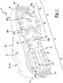
- the sole structure 200 includes a midsole 202 configured to provide cushioning characteristics to the sole structure 200, and an outsole 204 configured to provide a ground-engaging surface 26 of the article of footwear 10.
- each of the midsole 202 and the outsole 204 are formed compositely, whereby each is formed of multiple subcomponents.
- the midsole 202 includes a bladder 206 and a cushioning member 208 configured to receive the bladder 206.
- the outsole 204 includes a forefoot segment 210, a heel segment 212, and a pair of bladder segments 214.
- the subcomponents 206, 208, 210, 212, 214 are assembled and secured to each other using various methods of bonding, including adhesively bonding and melding, for example.
- the bladder 206 of the midsole 202 includes an opposing pair of barrier layers 216, 218, which can be joined to each other at discrete locations to define a chamber 220, a web area 222, and a peripheral seam 224.
- the barrier layers 216, 218 include a first, upper barrier layer 216 and a second, lower barrier layer 218.
- the chamber 220 can be produced from any suitable combination of one or more barrier layers.
- barrier layer encompasses both monolayer and multilayer films.
- one or both of barrier layers 216, 218 are each produced (e.g., thermoformed or blow molded) from a monolayer film (a single layer).
- one or both of barrier layers 216, 218 are each produced (e.g., thermoformed or blow molded) from a multilayer film (multiple sublayers).
- each layer or sublayer can have a film thickness ranging from about 0.2 micrometers to about be about 1 millimeter.
- the film thickness for each layer or sublayer can range from about 0.5 micrometers to about 500 micrometers.
- the film thickness for each layer or sublayer can range from about 1 micrometer to about 100 micrometers.
- the lower barrier layer 218 may have a greater thickness than the upper barrier layer 216, whereby the lower barrier layer 218 is configured to provide a portion of the ground-contacting surface 26 of the article of footwear.
- the bladder segments 214 of the outsole 204 may be integrally formed as part of the lower barrier layer 218.
- barrier layers 216, 218 can independently be transparent, translucent, and/or opaque.
- the upper barrier layer 216 may be transparent, while the lower barrier layer 218 is opaque.
- transparent for a barrier layer and/or a fluid-filled chamber means that light passes through the barrier layer in substantially straight lines and a viewer can see through the barrier layer. In comparison, for an opaque barrier layer, light does not pass through the barrier layer and one cannot see clearly through the barrier layer at all.
- a translucent barrier layer falls between a transparent barrier layer and an opaque barrier layer, in that light passes through a translucent layer but some of the light is scattered so that a viewer cannot see clearly through the layer.
- Barrier layers 216, 218 can each be produced from an elastomeric material that includes one or more thermoplastic polymers and/or one or more cross-linkable polymers.
- the elastomeric material can include one or more thermoplastic elastomeric materials, such as one or more thermoplastic polyurethane (TPU) copolymers, one or more ethylene-vinyl alcohol (EVOH) copolymers, and the like.
- urethane groups can contain additional groups such as ester, ether, urea, allophanate, biuret, carbodiimide, oxazolidinyl, isocynaurate, uretdione, carbonate, and the like, in addition to urethane groups.
- suitable isocyanates for producing the polyurethane copolymer chains include diisocyanates, such as aromatic diisocyanates, aliphatic diisocyanates, and combinations thereof.
- suitable aromatic diisocyanates include toluene diisocyanate (TDI), TDI adducts with trimethyloylpropane (TMP), methylene diphenyl diisocyanate (MDI), xylene diisocyanate (XDI), tetramethylxylylene diisocyanate (TMXDI), hydrogenated xylene diisocyanate (HXDI), naphthalene 1,5-diisocyanate (NDI), 1,5-tetrahydronaphthalene diisocyanate, para-phenylene diisocyanate (PPDI), 3,3' - dimethyldiphenyl-4, 4' -diisocyanate (DDDI), 4,4 '-dibenzyl diisocyanate (
- the polyurethane polymer chains are produced from diisocynates including HMDI, TDI, MDI, H12 aliphatics, and combinations thereof.
- the thermoplastic TPU can include polyester-based TPU, polyether-based TPU, polycaprolactone-based TPU, polycarbonate-based TPU, polysiloxane-based TPU, or combinations thereof.
- the polymeric layer can be formed of one or more of the following: EVOH copolymers, poly(vinyl chloride), polyvinylidene polymers and copolymers (e.g., polyvinylidene chloride), polyamides (e.g., amorphous polyamides), amide-based copolymers, acrylonitrile polymers (e.g., acrylonitrile-methyl acrylate copolymers), polyethylene terephthalate, polyether imides, polyacrylic imides, and other polymeric materials known to have relatively low gas transmission rates. Blends of these materials as well as with the TPU copolymers described herein and optionally including combinations of polyimides and crystalline polymers, are also suitable.
- the barrier layers 216, 218 may include two or more sublayers (multilayer film) such as shown in Mitchell et al., U.S. Patent No. 5,713,141 and Mitchell et al., U.S. Patent No. 5,952,065 , the disclosures of which are incorporated by reference in their entirety.
- suitable multilayer films include microlayer films, such as those disclosed in Bonk et al., U.S. Patent No. 6,582,786 , which is incorporated by reference in its entirety.
- barrier layers 216, 218 may each independently include alternating sublayers of one or more TPU copolymer materials and one or more EVOH copolymer materials, where the total number of sublayers in each of barrier layers 216, 218 includes at least four (4) sublayers, at least ten (10) sublayers, at least twenty (20) sublayers, at least forty (40) sublayers, and/or at least sixty (60) sublayers.
- the chamber 220 can be produced from barrier layers 216, 218 using any suitable technique, such as thermoforming (e.g. vacuum thermoforming), blow molding, extrusion, injection molding, vacuum molding, rotary molding, transfer molding, pressure forming, heat sealing, casting, low-pressure casting, spin casting, reaction injection molding, radio frequency (RF) welding, and the like.
- barrier layers 216, 218 can be produced by co-extrusion followed by vacuum thermoforming to produce an inflatable chamber 220, which can optionally include one or more valves (e.g., one way valves) that allows the chamber 220 to be filled with the fluid (e.g., gas).
- the chamber 220 can be provided in a fluid-filled (e.g., as provided in footwear 10) or in an unfilled state.
- the chamber 220 can be filled to include any suitable fluid, such as a gas or liquid.
- the gas can include air, nitrogen (N 2 ), or any other suitable gas.
- the chamber 220 can alternatively include other media, such as pellets, beads, ground recycled material, and the like (e.g., foamed beads and/or rubber beads).
- the fluid provided to the chamber 220 can result in the chamber 220 being pressurized.
- the fluid provided to the chamber 220 can be at atmospheric pressure such that the chamber 220 is not pressurized but, rather, simply contains a volume of fluid at atmospheric pressure.
- the chamber 220 desirably has a low gas transmission rate to preserve its retained gas pressure.
- the chamber 220 has a gas transmission rate for nitrogen gas that is at least about ten (10) times lower than a nitrogen gas transmission rate for a butyl rubber layer of substantially the same dimensions.
- the chamber 220 has a nitrogen gas transmission rate of 15 cubic-centimeter/square-meter•atmosphere•day (cm 3 /m 2 •atm•day) or less for an average film thickness of 500 micrometers (based on thicknesses of barrier layers 216, 218).
- the transmission rate is 10 cm 3 /m 2 •atm•day or less, 5 cm 3 /m 2 •atm•day or less, or 1 cm 3 /m 2 •atm•day or less.
- the upper barrier layer 216 and the lower barrier layer 218 cooperate to define a geometry (e.g., thicknesses, width, and lengths) of the chamber 220.
- the web area 222 and the peripheral seam 224 may cooperate to bound and extend around the chamber 220 to seal the fluid (e.g., air) within the chamber 220.
- the chamber 220 is associated with an area of the bladder 206 where interior surfaces of the upper and lower barrier layers 216, 218 are not joined together and, thus, are separated from one another.
- a space formed between opposing interior surfaces of the upper and lower barrier layers 216, 218 defines an interior void 226 of the chamber 220.
- exterior surfaces of the upper and lower barrier layers 216, 218 define an exterior profile of the chamber 220.
- the upper and lower barrier layers 216, 218 define respective upper and lower surfaces 228, 230 of the bladder 206.
- Thicknesses T C of the chamber 220 are defined by the distance between the upper and lower surfaces 228, 230 of the bladder 206, as discussed in greater detail below.
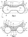
- the chamber 220 includes a plurality of segments 232, 234 that cooperate to provide characteristics of responsiveness and support to the midsole 202.
- the segments 232, 234 may be described as including a pair of cushions 232 that are connected (i.e., in fluid communication) with each other by one or more conduits 234.
- the cushions 232 of the chamber 220 are configured to be at least partially exposed along a peripheral edge of the sole structure 200.
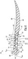
- each of the cushions 232 includes tubular body 236, a first terminal end 238 disposed at a first end of the tubular body 236, and a second terminal end 240 disposed at an opposite end of the tubular body 236 from the first terminal end 238.
- the tubular body 236 defines a substantially circular cross section that extends along a longitudinal axis A 232 of the cushion 232.
- the thickness T C of the tubular body 236 increases continuously along the longitudinal axis A 232 from a first thickness T C1 at the first terminal end 238 to a second thickness T C2 at the second terminal end 240.
- the thickness T C of the tubular body 236 may be described as tapering along the direction from the second terminal end 240 to the first terminal end 238.
- each cushion 232 are substantially dome-shaped, and each includes compound curvatures associated with the respective upper and lower barrier layers 216, 218.
- the first terminal end 238 of each cushion 232 is formed where an end portion of the upper barrier layer 216 converges with and is joined to the lower barrier layer 218 at the peripheral seam 224 to enclose an anterior end of the tubular body 236.
- the upper barrier layer 216 has a first portion extending from the tubular body 236 and having a first radius R1, and a second portion extending between the first portion and the peripheral seam 224 and having a second radius R2.
- the lower barrier layer 218 has a third portion extending between the tubular body 236 and the peripheral seam 224 and having a third radius R3.
- the second radius R2 is greater than the first radius R1 and the third radius R3, whereby the second radius R2 provides a relatively flat-faced profile to an intermediate portion of the first terminal end 238.
- the third radius R3 may be less than the first radius R1.
- each cushion 232 is formed where another end portion of the upper barrier layer 216 converges with and is joined to the lower barrier layer 218 at the peripheral seam 224 to enclose the opposite end of the tubular body 236.
- the upper barrier layer 216 includes a fourth portion having a fourth radius R4 extending from the tubular body 236 and a fifth portion having a fifth radius R5 between the fourth portion and the peripheral seam 224.
- the lower barrier layer 218 includes a sixth portion having a sixth radius R6 extending between the tubular body 236 and the peripheral seam 224.
- the fifth radius R5 is greater than the fourth radius R4 and the sixth radius R6, whereby the fifth radius R5 provides a relatively flat-faced profile to an intermediate portion of the second terminal end 240.
- the sixth radius R6 may be less than the fourth radius R4.
- each of the cushions 232 defines a respective longitudinal axis A 232 that extends from the first terminal end 238 to the second terminal end 240.
- the cushions 232 are spaced apart from each other along a direction transverse to the longitudinal axes A 232 of each of the cushions 232. More particularly, when the bladder 206 is assembled within the sole structure 200, the cushions 232 are spaced apart from each other along a lateral direction of the article of footwear 10, substantially perpendicular to the longitudinal axis A F of the article of footwear 10.
- the longitudinal axes A 232 of the cushions 232 converge with each other and with the longitudinal axis A F of the article of footwear 10 along the direction from the posterior end 20 to the anterior end 18. Accordingly, a lateral distance D1 between the cushions 232 is greater at the second terminal ends 240 than at the first terminal ends 238.
- the chamber 220 further includes at least one conduit 234 extending between and fluidly coupling the cushions 232.
- the chamber 220 includes a plurality of the conduits 234 connecting the tubular bodies 236 of the cushions 232 to each other.
- the conduits 234 each extend along respective longitudinal axes A 234 that are transverse to the longitudinal axes A 232 of the cushions 232. As best shown in FIGS.
- the conduits 234 include a first conduit 234 extending between the tubular bodies 236 of the cushions 232 adjacent to the first terminal ends 238, a second conduit 234 extending between the tubular bodies 236 of the cushions 232 adj acent to the second terminal ends 240, and a third conduit 234 disposed between the first conduit 234 and the second conduit 234 and connecting intermediate portions of the tubular bodies 236. Accordingly, the first conduit 234 and the second conduit 234 are disposed on opposite sides of the third conduit 234.
- the conduits 234 are defined by the cooperation of the upper barrier layer 216 and the lower barrier layer 218.
- the upper barrier layer 216 and the lower barrier layer 218 are formed to provide a plurality of semi-cylindrically shaped conduits 234, each having a substantially similar third thickness T C3 that is less than the first thickness T C1 and the second thickness T C2 of the cushions 232.
- a profile of each of the conduits 234 is substantially imparted by the upper barrier layer 216, whereby the upper barrier layer 216 is molded to define a curved upper portion of each conduit 234 while the lower barrier layer 218 is provided as substantially flat lower portion of each of the conduits 234.
- the lower barrier layer 216 may bulge from the web area 222 when the interior void 226 of the chamber 220 is pressurized and the lower barrier layer 218 is biased apart from the upper barrier layer 216, as illustrated in FIG. 6 .
- each of the conduits 234, defined by the upper barrier layer 216 are aligned with each other along a first conduit plane P 234-1 .
- the bottom-most portions of each of the conduits 234, defined by the lower barrier layer 218, are aligned with each other along a second conduit plane P 234-1 .
- the web area 222 of the bladder 206 may be recessed from each of the first conduit plane P 234-1 and the second conduit plane P 234-2 .
- the first and second conduit planes P 234-1 , P 234-2 are recessed from first and second cushion planes P 232-1 , P 232-2 formed by the upper-most and lower-most surfaces of the cushions 232, as best shown in FIG. 4 .
- the web area 222 is formed at a bonded region of the upper barrier layer 216 and the lower barrier layer 218, and extends between and connects each of the segments 232, 234 of the chamber 220.
- the web area 222 includes an anterior portion extending between and connecting the first terminal ends 238 of the respective cushions 232, and defining a first terminal edge 242 at an anterior end of the bladder 206.
- a posterior portion of the web area 222 extends between and connects the second terminal ends 240 of the cushions 232 and forms a second terminal edge 244 at a posterior end of the bladder 206.
- Intermediate portions of the web area 222 extend between and connect adjacent ones of the conduits 234 and the cushions 232.
- the intermediate portions of the web area 222 may be completely surrounded by the chamber 220.
- the web area 222 is disposed vertically intermediate with respect to the thickness T C of the fluid-filled chamber 220. Put another way, the web area 222 is recessed from the cushion planes P 232-1 , P 232-2 and the conduit planes P 234-1 , P 234-2 .
- the web area 222 includes an inflation conduit 248 configured to provide a fluid passage between a mold cavity (not shown) and the interior of the chamber 220.
- the inflation conduit 248 extends from an inlet 250 formed adjacent to the posterior, second terminal edge 244 of the web area 222 to the posterior-most one of the conduits 234 of the fluid-filled chamber 220.
- the upper and lower barrier layers 216, 218 are formed by respective mold portions each defining various surfaces for forming depressions and pinched surfaces corresponding to locations where the web area 222 and/or the peripheral seam 224 are formed when the upper barrier layer 216 and the lower barrier layer 218 are joined and bonded together.
- adhesive bonding joins the upper barrier layer 216 and the lower barrier layer 218 to form the web area 222 and the peripheral seam 224.
- the upper barrier layer 216 and the lower barrier layer 218 are joined to form the web area 222 and the peripheral seam 224 by thermal bonding.
- one or both of the barrier layers 216, 218 are heated to a temperature that facilitates shaping and melding.
- the barrier layers 216, 218 are heated prior to being located between their respective molds.
- the mold may be heated to raise the temperature of the barrier layers 216, 218.
- a molding process used to form the fluid-filled chamber 220 incorporates vacuum ports within mold portions to remove air such that the upper and lower barrier layers 216, 218 are drawn into contact with respective mold portions.
- fluids such as air may be injected into areas between the upper and lower barrier layers 216, 218 such that pressure increases cause the barrier layers 216, 218 to engage with surfaces of their respective mold portions.
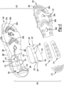
- the cushioning member 208 includes a top surface 260 and a bottom surface 262 formed on an opposite side of the cushioning member 208 from the top surface 260.
- a peripheral surface 264 extends between the top surface 260 and the bottom surface 262, and forms an outer periphery of the sole structure 200.
- the top surface 260 of the cushioning member 208 defines a profile of the footbed, and may be contoured to correspond to a shape of the foot.
- the bottom surface 262 of the cushioning member 208 is configured to cooperate with the bladder 206, whereby the bottom surface 262 includes a pocket 266 formed in the heel region 16 and configured to interface with the upper barrier layer 216 of the bladder 206.
- the pocket 266 includes a pair of recesses 268 extending along opposite sides of the cushioning member 208, which are configured to receive the cushions 232 of the bladder 206.
- the recesses 268 may extend through the peripheral surface 264 on the medial side 24 and the lateral side 22 of the cushioning member 208, whereby the cushions 232 of the bladder 206 are exposed and partially protrude from the peripheral surface 264 of the cushioning member 208.
- the pocket 266 may be formed with a central spine 270 extending continuously between the recesses 268 along the direction of the longitudinal axis A F of the article of footwear 10.
- the spine 270 includes a plurality of fingers 272 configured to extend into the recessed portions of the bladder 206 defined by the web area 222. Accordingly, a distal end 274 of each of the fingers 272 opposes and interfaces with the upper barrier layer 216 in the web area 222 of the bladder 206, as best shown in FIGS. 5 and 6 .
- the spine 270 further defines a plurality of channels 276 extending along a lateral direction, transverse to the longitudinal axis A F of the article of footwear 10, and configured to receive the portions of the conduits 234 formed by the upper barrier layer 216 of the bladder 206.
- the cooperation of the spine 270, the web area 222, and the conduits 234 provides a desired degree of flexibility along the heel region 16 of the sole structure 200.
- the cushioning member 208 includes a pair of grooves 278a, 278b formed in the bottom surface 262 and extending along the lateral direction from the peripheral surface 264 on the lateral side 22 to the peripheral surface 264 on the medial side 24.
- Each of the grooves 278a, 278b includes a chevron-shaped intermediate portion 280a, 280b, which includes a cavity 282a, 282b formed therein. Accordingly, the cavity 282a, 282b formed in the intermediate portion 280a, 280b of each groove 278a, 278b may be recessed further within the bottom surface 262 than the remainder of the groove 278a, 278b.
- a first one of the grooves 278a is formed along the intersection between the toe portion 12 T and the ball portion 12 B of the forefoot region 12, while a second one of the grooves 278b is formed along the intersection of the forefoot region 12 and the mid-foot region 14.
- the cushioning member 208 may further include one or more depressions 284a, 284b formed in the bottom surface 262. As shown, the depressions 284a, 284b are centrally disposed between the lateral side 22 and the medial side 24 of the cushioning member 208. A first one of the depressions 284a is longitudinally disposed between the first groove 278a and the second groove 278b, and has a substantially triangular or arrowhead-like shape. A second one of the depressions 284b is longitudinally disposed between the second groove 278b and the pocket 266, and has a substantially diamond-like shape.
- the cushioning member 208 is formed of a resilient polymeric material, such as foam or rubber, to impart properties of cushioning, responsiveness, and energy distribution to the foot of the wearer.
- Example resilient polymeric materials for the cushioning member 208 may include those based on foaming or molding one or more polymers, such as one or more elastomers (e.g., thermoplastic elastomers (TPE)).
- the one or more polymers may include aliphatic polymers, aromatic polymers, or mixtures of both; and may include homopolymers, copolymers (including terpolymers), or mixtures of both.
- the one or more polymers may include olefinic homopolymers, olefinic copolymers, or blends thereof.
- olefinic polymers include polyethylene, polypropylene, and combinations thereof.
- the one or more polymers may include one or more ethylene copolymers, such as, ethylene-vinyl acetate (EVA) copolymers, EVOH copolymers, ethylene-ethyl acrylate copolymers, ethylene-unsaturated mono-fatty acid copolymers, and combinations thereof.
- EVA ethylene-vinyl acetate
- the one or more polymers may include one or more polyacrylates, such as polyacrylic acid, esters of polyacrylic acid, polyacrylonitrile, polyacrylic acetate, polymethyl acrylate, polyethyl acrylate, polybutyl acrylate, polymethyl methacrylate, and polyvinyl acetate; including derivatives thereof, copolymers thereof, and any combinations thereof.
- polyacrylates such as polyacrylic acid, esters of polyacrylic acid, polyacrylonitrile, polyacrylic acetate, polymethyl acrylate, polyethyl acrylate, polybutyl acrylate, polymethyl methacrylate, and polyvinyl acetate; including derivatives thereof, copolymers thereof, and any combinations thereof.
- the one or more polymers may include one or more ionomeric polymers.
- the ionomeric polymers may include polymers with carboxylic acid functional groups, sulfonic acid functional groups, salts thereof (e.g., sodium, magnesium, potassium, etc.), and/or anhydrides thereof.
- the ionomeric polymer(s) may include one or more fatty acid-modified ionomeric polymers, polystyrene sulfonate, ethylene-methacrylic acid copolymers, and combinations thereof.
- the one or more polymers may include one or more styrenic block copolymers, such as acrylonitrile butadiene styrene block copolymers, styrene acrylonitrile block copolymers, styrene ethylene butylene styrene block copolymers, styrene ethylene butadiene styrene block copolymers, styrene ethylene propylene styrene block copolymers, styrene butadiene styrene block copolymers, and combinations thereof.
- styrenic block copolymers such as acrylonitrile butadiene styrene block copolymers, styrene acrylonitrile block copolymers, styrene ethylene butylene styrene block copolymers, styrene ethylene butadiene styrene block
- the one or more polymers may include one or more polyamide copolymers (e.g., polyamide-polyether copolymers) and/or one or more polyurethanes (e.g., crosslinked polyurethanes and/or thermoplastic polyurethanes).
- suitable polyurethanes include those discussed above for barrier layers 216, 218.
- the one or more polymers may include one or more natural and/or synthetic rubbers, such as butadiene and isoprene.
- the foamed material may be foamed using a physical blowing agent which phase transitions to a gas based on a change in temperature and/or pressure, or a chemical blowing agent which forms a gas when heated above its activation temperature.
- the chemical blowing agent may be an azo compound such as adodicarbonamide, sodium bicarbonate, and/or an isocyanate.
- the foamed polymeric material may be a crosslinked foamed material.
- a peroxide-based crosslinking agent such as dicumyl peroxide may be used.
- the foamed polymeric material may include one or more fillers such as pigments, modified or natural clays, modified or unmodified synthetic clays, talc glass fiber, powdered glass, modified or natural silica, calcium carbonate, mica, paper, wood chips, and the like.
- the resilient polymeric material may be formed using a molding process.
- the uncured elastomer e.g., rubber
- a curing package such as a sulfur-based or peroxide-based curing package, calendared, formed into shape, placed in a mold, and vulcanized.
- the resilient polymeric material when the resilient polymeric material is a foamed material, the material may be foamed during a molding process, such as an injection molding process.
- a thermoplastic polymeric material may be melted in the barrel of an injection molding system and combined with a physical or chemical blowing agent and optionally a crosslinking agent, and then injected into a mold under conditions which activate the blowing agent, forming a molded foam.
- the foamed material when the resilient polymeric material is a foamed material, the foamed material may be a compression molded foam. Compression molding may be used to alter the physical properties (e.g., density, stiffness and/or durometer) of a foam, or to alter the physical appearance of the foam (e.g., to fuse two or more pieces of foam, to shape the foam, etc.), or both.
- Compression molding may be used to alter the physical properties (e.g., density, stiffness and/or durometer) of a foam, or to alter the physical appearance of the foam (e.g., to fuse two or more pieces of foam, to shape the foam, etc.), or both.
- the compression molding process desirably starts by forming one or more foam preforms, such as by injection molding and foaming a polymeric material, by forming foamed particles or beads, by cutting foamed sheet stock, and the like.
- the compression molded foam may then be made by placing the one or more preforms formed of foamed polymeric material(s) in a compression mold, and applying sufficient pressure to the one or more preforms to compress the one or more preforms in a closed mold.
- the mold is closed, sufficient heat and/or pressure is applied to the one or more preforms in the closed mold for a sufficient duration of time to alter the preform(s) by forming a skin on the outer surface of the compression molded foam, fuse individual foam particles to each other, permanently increase the density of the foam(s), or any combination thereof.
- the mold is opened and the molded foam article is removed from the mold.
- the outsole 204 includes the forefoot segment 210 and the heel segment 212 attached to the bottom surface 262 of the cushioning member 208, and the bladder segments 214 attached to the lower barrier layer 218 of the bladder 206.
- the forefoot segment 210 of the outsole 204 includes a plurality of cutouts 286a-286d corresponding to the cavities 282a, 282b and the depressions 284a, 284b of the cushioning member 208.
- shapes of the cutouts 286a-286d correspond to the shapes of the cavities 282a, 282b and the depressions 284a, 284b such that the cavities 282a, 282b and the depressions 284a, 284b are exposed to the ground surface through the cutouts 286a-286d.
- the forefoot segment 210 of the outsole 204 may further include a toe cap 288 configured to extend over and protect the anterior end 18 of the upper 100.
- the outsole segments 210, 212, 214 are formed of resilient materials configured to impart properties of abrasion resistance and traction to the sole structure 200.
- One or more of the outsole segments 210, 212, 214 may be formed of a first material having a higher durometer than the others of the outsole segments 210, 212, 214.
- the bladder segments 214 may be formed of a rubber material having a first durometer, while the forefoot segment 210 and the heel segment 212 is formed of a foam material having a second durometer, less than the first durometer.
- the bladder segments 214 may be integrally formed or overmolded with the cushions 232 of the bladder 206, such that the bladder segments 214 are part of the cushions 232 and the cushions 232 are exposed through the bottom surface 262 of the cushioning member 208.
- a bladder comprising a first fluid-filled segment including a first terminal end and a second terminal end disposed on opposite ends of the first fluid-filled segment along a first longitudinal axis of the first fluid-filled segment, and a second fluid-filled segment including a third terminal end and a fourth terminal end disposed on opposite ends of the second fluid-filled segment along a second longitudinal axis of the second fluid-filled segment, the second fluid-filled segment being (i) spaced apart from the first fluid-filled segment in a first direction transverse to the first longitudinal axis and the second longitudinal axis and (ii) convergent with the first fluid-filled segment.
- Clause 2 The bladder of Clause 1, further comprising a third fluid-filled segment extending between the first fluid-filled segment and the second fluid-filled segment.
- Clause 3 The bladder of Clause 2, wherein the third fluid-filled segment fluidly couples the first fluid-filled segment and the second fluid-filled segment.
- Clause 4 The bladder of Clause 2, wherein the third fluid-filled segment is disposed transverse to the first longitudinal axis and the second longitudinal axis.
- Clause 5 The bladder of Clause 2, further comprising a fourth fluid-filled segment and a fifth fluid-filled segment disposed on opposite sides of the third fluid-filled segment in a direction extending along the first longitudinal axis and the second longitudinal axis.
- Clause 6 The bladder of Clause 5, wherein the fourth fluid-filled segment and the fifth fluid-filled segment fluidly couple the first fluid-filled segment and the second fluid-filled segment.
- Clause 7 The bladder of Clause 5, further comprising a web area extending between the third fluid-filled segment and the fourth fluid-filled segment and between the third fluid-filled segment and the fifth fluid-filled segment.
- Clause 8 The bladder of Clause 7, wherein the web area is recessed from a plane extending tangent to a first outer surface of the third fluid-filled segment, the fourth fluid-filled segment, and the fifth fluid-filled segment on a first side of the bladder.
- Clause 9 The bladder of Clause 8, wherein the web area is recessed from a plane extending tangent to a second outer surface of the third fluid-filled segment, the fourth fluid-filled segment, and the fifth fluid-filled segment on a second side of the bladder, the second side of the bladder being formed on an opposite side of the bladder than the first side.
- Clause 10 The bladder of Clause 1, wherein the bladder is formed from a first barrier sheet and a second barrier sheet.
- Clause 11 The bladder of Clause 10, wherein the first barrier sheet and the second barrier sheet are formed from the same material.
- Clause 12 The bladder of Clause 10, wherein the first barrier sheet and the second barrier sheet are formed from different materials.
- Clause 13 The bladder of Clause 10, wherein one of the first barrier sheet and the second barrier sheet is substantially transparent and the other of the first barrier sheet and the second barrier sheet is opaque.
- Clause 14 The bladder of Clause 1, wherein the first fluid-filled segment tapers in a direction along the first longitudinal axis and the second fluid-filled segment tapers in a direction along the second longitudinal axis.
- Clause 15 A sole structure incorporating the bladder of Clause 1.
- Clause 16 The sole structure of Clause 15, wherein the first fluid-filled segment and the second fluid-filled segment converge in a direction from a heel region to a forefoot region of the sole structure.
- Clause 17 An article of footwear incorporating the bladder of Clause 1.
- Clause 18 The article of footwear of Clause 17, wherein the first fluid-filled segment and the second fluid-filled segment converge in a direction from a heel region to a forefoot region of the article of footwear.
- Clause 19 The article of footwear of Clause 17, wherein the first fluid-filled segment and the second fluid-filled segment are exposed at a ground-contacting surface of the article of footwear.
- Clause 20 The article of footwear of Clause 19, wherein the first fluid-filled segment is exposed at one of a medial side and a lateral side of a sole structure of the article of footwear and the second fluid-filled segment is exposed at the other of the medial side and the lateral side of the sole structure of the article of footwear.
- An article of footwear comprising a bladder comprising a first fluid-filled segment including a first terminal end and a second terminal end disposed on opposite ends of the first fluid-filled segment along a first longitudinal axis of the first fluid-filled segment, the first longitudinal axis extending in a first direction from a heel region of the article of footwear to a forefoot region of the article of footwear, a second fluid-filled segment spaced apart from the first fluid-filled segment in a second direction transverse to the first direction and including a third terminal end and a fourth terminal end disposed on opposite ends of the second fluid-filled segment along a second longitudinal axis of the second fluid-filled segment, and a third fluid-filled segment extending in the second direction between the first fluid-filled segment and the second fluid-filled segment.
- Clause 22 The article of footwear of Clause 21, wherein the first fluid-filled segment and the second fluid-filled segment are convergent.
- Clause 23 The article of footwear of Clause 22, wherein the first fluid-filled segment and the second fluid-filled segment converge in a direction from the heel region to the forefoot region.
- Clause 24 The article of footwear of Clause 21, wherein the third fluid-filled segment fluidly couples the first fluid-filled segment and the second fluid-filled segment.
- Clause 25 The article of footwear of Clause 22, further comprising a fourth fluid-filled segment and a fifth fluid-filled segment disposed on opposite sides of the third fluid-filled segment in the first direction.
- Clause 26 The article of footwear of Clause 25, wherein the fourth fluid-filled segment and the fifth fluid-filled segment fluidly couple the first fluid-filled segment and the second fluid-filled segment.
- Clause 27 The article of footwear of Clause 25, further comprising a web area extending between the third fluid-filled segment and the fourth fluid-filled segment and between the third fluid-filled segment and the fifth fluid-filled segment.
- Clause 28 The article of footwear of Clause 27, wherein the web area is recessed from a plane extending tangent to a first outer surface of the third fluid-filled segment, the fourth fluid-filled segment, and the fifth fluid-filled segment on a first side of the bladder.
- Clause 29 The article of footwear of Clause 28, wherein the web area is recessed from a plane extending tangent to a second outer surface of the third fluid-filled segment, the fourth fluid-filled segment, and the fifth fluid-filled segment on a second side of the bladder, the second side of the bladder being formed on an opposite side of the bladder than the first side.
- Clause 30 The article of footwear of Clause 21, wherein the bladder is formed from a first barrier sheet and a second barrier sheet.
- Clause 31 The article of footwear of Clause 30, wherein the first barrier sheet and the second barrier sheet are formed from the same material.
- Clause 32 The article of footwear of Clause 30, wherein the first barrier sheet and the second barrier sheet are formed from different materials.
- Clause 33 The article of footwear of Clause 30, wherein one of the first barrier sheet and the second barrier sheet is substantially transparent and the other of the first barrier sheet and the second barrier sheet is opaque.
- Clause 34 The article of footwear of Clause 33, wherein the other of the first barrier sheet and the second barrier sheet forms a ground-contacting surface of the article of footwear.
- Clause 35 The article of footwear of Clause 21, wherein the first fluid-filled segment tapers in a direction along the first longitudinal axis and the second fluid-filled segment tapers in a direction along the second longitudinal axis.
- Clause 36 The article of footwear of Clause 21, wherein the first fluid-filled segment and the second fluid-filled segment are exposed at a ground-contacting surface of the article of footwear.
- Clause 37 The article of footwear of Clause 21, wherein the first fluid-filled segment is exposed at one of a medial side and a lateral side of a sole structure of the article of footwear and the second fluid-filled segment is exposed at the other of the medial side and the lateral side of the sole structure of the article of footwear.
Abstract
Description
- This application claims priority to
U.S. Non-provisional Application Serial No. 16/825,363, filed March 20, 2020 U.S. Provisional Application Serial No. 62/825,098, filed March 28, 2019 - The present disclosure relates generally to sole structures for articles of footwear and more particularly to sole structures incorporating a fluid-filled bladder.
- This section provides background information related to the present disclosure which is not necessarily prior art.
- Articles of footwear conventionally include an upper and a sole structure. The upper may be formed from any suitable material(s) to receive, secure, and support a foot on the sole structure. The upper may cooperate with laces, straps, or other fasteners to adjust the fit of the upper around the foot. A bottom portion of the upper, proximate to a bottom surface of the foot, attaches to the sole structure.
- Sole structures generally include a layered arrangement extending between a ground surface and the upper. One layer of the sole structure includes an outsole that provides abrasion-resistance and traction with the ground surface. The outsole may be formed from rubber or other materials that impart durability and wear-resistance, as well as enhance traction with the ground surface. Another layer of the sole structure includes a midsole disposed between the outsole and the upper. The midsole provides cushioning for the foot and may be partially formed from a polymer foam material that compresses resiliently under an applied load to cushion the foot by attenuating ground-reaction forces. The midsole may additionally or alternatively incorporate a fluid-filled bladder to increase the durability of the sole structure, as well as to provide cushioning to the foot by compressing resiliently under an applied load to attenuate ground-reaction forces. Sole structures may also include a comfort-enhancing insole or a sockliner located within a void proximate to the bottom portion of the upper and a strobel attached to the upper and disposed between the midsole and the insole or sockliner.
- Midsoles employing fluid-filled bladders typically include a bladder formed from two barrier layers of polymer material that are sealed or bonded together. The fluid-filled bladders are pressurized with a fluid such as air, and may incorporate tensile members within the bladder to retain the shape of the bladder when compressed resiliently under applied loads, such as during athletic movements. Generally, bladders are designed with an emphasis on balancing support for the foot and cushioning characteristics that relate to responsiveness as the bladder resiliently compresses under an applied load
- The drawings described herein are for illustrative purposes only of selected configurations and are not intended to limit the scope of the present disclosure.
-
FIG. 1 is a bottom perspective view of an article of footwear in accordance with principles of the present disclosure; -
FIG. 2 is an exploded view of a sole structure of the article of footwear ofFIG. 1 , showing a sole structure having a midsole and an outsole; -
FIG. 3 is a bottom plan view of the midsole ofFIG. 2 ; -
FIG. 4 is a cross-sectional view of the midsole ofFIG. 3 , taken along line 4-4 ofFIG. 3 ; -
FIG. 5 is a cross-sectional view of the midsole ofFIG. 3 , taken along line 5-5 ofFIG. 3 ; -
FIG. 6 is a cross-sectional view of the midsole ofFIG. 3 , taken along line 6-6 ofFIG. 3 ; -
FIG. 7 is a top plan view of a bladder of the article of footwear ofFIG. 1 ; and -
FIG. 8 is a cross-sectional view of the bladder ofFIG. 7 , taken along line 8-8 ofFIG. 7 . - Corresponding reference numerals indicate corresponding parts throughout the drawings.
- Example configurations will now be described more fully with reference to the accompanying drawings. Example configurations are provided so that this disclosure will be thorough, and will fully convey the scope of the disclosure to those of ordinary skill in the art. Specific details are set forth such as examples of specific components, devices, and methods, to provide a thorough understanding of configurations of the present disclosure. It will be apparent to those of ordinary skill in the art that specific details need not be employed, that example configurations may be embodied in many different forms, and that the specific details and the example configurations should not be construed to limit the scope of the disclosure.
- The terminology used herein is for the purpose of describing particular exemplary configurations only and is not intended to be limiting. As used herein, the singular articles "a," "an," and "the" may be intended to include the plural forms as well, unless the context clearly indicates otherwise. The terms "comprises," "comprising," "including," and "having," are inclusive and therefore specify the presence of features, steps, operations, elements, and/or components, but do not preclude the presence or addition of one or more other features, steps, operations, elements, components, and/or groups thereof. The method steps, processes, and operations described herein are not to be construed as necessarily requiring their performance in the particular order discussed or illustrated, unless specifically identified as an order of performance. Additional or alternative steps may be employed.
- When an element or layer is referred to as being "on," "engaged to," "connected to," "attached to," or "coupled to" another element or layer, it may be directly on, engaged, connected, attached, or coupled to the other element or layer, or intervening elements or layers may be present. In contrast, when an element is referred to as being "directly on," "directly engaged to," "directly connected to," "directly attached to," or "directly coupled to" another element or layer, there may be no intervening elements or layers present. Other words used to describe the relationship between elements should be interpreted in a like fashion (e.g., "between" versus "directly between," "adjacent" versus "directly adjacent," etc.). As used herein, the term "and/or" includes any and all combinations of one or more of the associated listed items.
- The terms first, second, third, etc. may be used herein to describe various elements, components, regions, layers and/or sections. These elements, components, regions, layers and/or sections should not be limited by these terms. These terms may be only used to distinguish one element, component, region, layer or section from another region, layer or section. Terms such as "first," "second," and other numerical terms do not imply a sequence or order unless clearly indicated by the context. Thus, a first element, component, region, layer or section discussed below could be termed a second element, component, region, layer or section without departing from the teachings of the example configurations.
- One aspect of the disclosure provides a bladder for a sole structure for an article of footwear. The bladder includes a first fluid-filled segment including a first terminal end and a second terminal end disposed on opposite ends of the first fluid-filled segment along a first longitudinal axis of the first fluid-filled segment. The bladder also includes a second fluid-filled segment including a third terminal end and a fourth terminal end disposed on opposite ends of the second fluid-filled segment along a second longitudinal axis of the second fluid-filled segment. The second fluid-filled segment is (i) spaced apart from the first fluid-filled segment in a first direction transverse to the first longitudinal axis and the second longitudinal axis and (ii) is convergent with the first fluid-filled segment.
- Implementations of the disclosure may include one or more of the following optional features. In some examples, the bladder includes a third fluid-filled segment extending between the first fluid-filled segment and the second fluid-filled segment. Here, the third fluid-filled segment may fluidly couple the first fluid-filled segment and the second fluid-filled segment. Optionally, the third fluid-filled segment may be disposed transverse to the first longitudinal axis and the second longitudinal axis.
- In some implementations, a fourth fluid-filled segment and a fifth fluid-filled segment are disposed on opposite sides of the third fluid-filled segment in a direction extending along the first longitudinal axis and the second longitudinal axis. Here, the fourth fluid-filled segment and the fifth fluid-filled segment may fluidly couple the first fluid-filled segment and the second fluid-filled segment. The bladder may include a web area extending between the third fluid-filled segment and the fourth fluid-filled segment and between the third fluid-filled segment and the fifth fluid-filled segment. Here, the web area may be recessed from a plane extending tangent to a first outer surface of the third fluid-filled segment, the fourth fluid-filled segment, and the fifth fluid-filled segment on a first side of the bladder. Optionally, the web area is recessed from a plane extending tangent to a second outer surface of the third fluid-filled segment, the fourth fluid-filled segment, and the fifth fluid-filled segment on a second side of the bladder, the second side of the bladder being formed on an opposite side of the bladder than the first side.
- In some configurations, the bladder is formed from a first barrier sheet and a second barrier sheet. The first barrier sheet and the second barrier sheet may be formed from the same material. Optionally, the first barrier sheet and the second barrier sheet may be formed from different materials. One of the first barrier sheet and the second barrier sheet may be substantially transparent and the other of the first barrier sheet and the second barrier sheet may be opaque.
- In some implementations, the first fluid-filled segment may taper in a direction along the first longitudinal axis and the second fluid-filled segment may taper in a direction along the second longitudinal axis.
- In some examples, the bladder is incorporated into the sole structure for the article of footwear. Here, the first fluid-filled segment and the second fluid-filled segment may converge in a direction from a heel region to a forefoot region of the sole structure.
- In some examples, the bladder is incorporated into an article of footwear. Here, the first fluid-filled segment and the second fluid-filled segment may converge in a direction from a heel region to a forefoot region of the article of footwear. Additionally or alternatively, the first fluid-filled segment and the second fluid-filled segment may be exposed at a ground-contacting surface of the article of footwear. The first fluid-filled segment may be exposed at one of a medial side and a lateral side of a sole structure of the article of footwear and the second fluid-filled segment may be exposed at the other of the medial side and the lateral side of the sole structure of the article of footwear.
- Another aspect of the disclosure provides an article of footwear. The article of footwear includes a bladder. The bladder includes a first fluid-filled segment including a first terminal end and a second terminal end disposed on opposite ends of the first fluid-filled segment along a first longitudinal axis of the first fluid-filled segment. The first longitudinal axis extends in a first direction from a heel region of the article of footwear to a forefoot region of the article of footwear. A second fluid-filled segment is spaced apart from the first fluid-filled segment in a second direction transverse to the first direction and includes a third terminal end and a fourth terminal end disposed on opposite ends of the second fluid-filled segment along a second longitudinal axis of the second fluid-filled segment. The bladder further includes a third fluid-filled segment extending in the second direction between the first fluid-filled segment and the second fluid-filled segment.
- Implementations of this aspect of the disclosure may include one or more of the following optional features. In some implementations, the first fluid-filled segment and the second fluid-filled segment are convergent. The first fluid-filled segment and the second fluid-filled segment may converge in a direction from the heel region to the forefoot region. The third fluid-filled segment may fluidly couple the first fluid-filled segment and the second fluid-filled segment. A fourth fluid-filled segment and a fifth fluid-filled segment may be disposed on opposite sides of the third fluid-filled segment in the first direction. The fourth fluid-filled segment and the fifth fluid-filled segment may fluidly couple the first fluid-filled segment and the second fluid-filled segment. A web area may extend between the third fluid-filled segment and the fourth fluid-filled segment and between the third fluid-filled segment and the fifth fluid-filled segment. The web area may be recessed from a plane extending tangent to a first outer surface of the third fluid-filled segment, the fourth fluid-filled segment, and the fifth fluid-filled segment on a first side of the bladder. Optionally, the web area may be recessed from a plane extending tangent to a second outer surface of the third fluid-filled segment, the fourth fluid-filled segment, and the fifth fluid-filled segment on a second side of the bladder, the second side of the bladder being formed on an opposite side of the bladder than the first side.
- In some configurations, the bladder is formed from a first barrier sheet and a second barrier sheet. Here, the first barrier sheet and the second barrier sheet may be formed from the same material or the first barrier sheet and the second barrier sheet may be formed from different materials. One of the first barrier sheet and the second barrier sheet may be substantially transparent and the other of the first barrier sheet and the second barrier sheet may be opaque. Here, the other of the first barrier sheet and the second barrier sheet may form a ground-contacting surface of the article of footwear.
- In some examples, the first fluid-filled segment tapers in a direction along the first longitudinal axis and the second fluid-filled segment tapers in a direction along the second longitudinal axis. The first fluid-filled segment and the second fluid-filled segment may be exposed at a ground-contacting surface of the article of footwear. Optionally, the first fluid-filled segment may be exposed at one of a medial side and a lateral side of a sole structure of the article of footwear and the second fluid-filled segment may be exposed at the other of the medial side and the lateral side of the sole structure of the article of footwear.
- Referring to
FIGS. 1-8 , an article offootwear 10 includes an upper 100 and asole structure 200. The article offootwear 10 may be divided into one or more regions. The regions may include aforefoot region 12, amid-foot region 14, and aheel region 16. Theforefoot region 12 may be subdivided into atoe portion 12T corresponding with phalanges, and aball portion 12B associated with metatarsal bones of a foot. Themid-foot region 14 may correspond with an arch area of the foot, and theheel region 16 may correspond with rear portions of the foot, including a calcaneus bone. Thefootwear 10 may further include ananterior end 18 associated with a forward-most point of the forefoot region, and aposterior end 20 associated with a rearward-most point of theheel region 16. A longitudinal axis AF of thefootwear 10 extends along a length of thefootwear 10 from theanterior end 18 to theposterior end 20, and generally divides thefootwear 10 into alateral side 22 and amedial side 24. Accordingly, thelateral side 22 and themedial side 24 respectively correspond with opposite sides of thefootwear 10 and extend through theregions - The upper 100 includes interior surfaces that define an interior void 102 configured to receive and secure a foot for support on
sole structure 200. The upper 100 may be formed from one or more materials that are stitched or adhesively bonded together to form the interior void 102. Suitable materials of the upper may include, but are not limited to, mesh, textiles, foam, leather, and synthetic leather. The materials may be selected and located to impart properties of durability, air-permeability, wear-resistance, flexibility, and comfort. - In some examples, the upper 100 includes a strobel having a bottom surface opposing the
sole structure 200 and an opposing top surface defining a footbed of the interior void 102. Stitching or adhesives may secure the strobel to the upper 100. The footbed may be contoured to conform to a profile of the bottom surface (e.g., plantar) of the foot. Optionally, the upper 100 may also incorporate additional layers such as an insole or sockliner that may be disposed upon the strobel and reside within the interior void 102 of the upper 100 to receive a plantar surface of the foot to enhance the comfort of the article offootwear 10. An ankle opening 104 in theheel region 16 may provide access to the interior void 102. For example, the ankle opening 104 may receive a foot to secure the foot within the void 102 and facilitate entry and removal of the foot from and to the interior void 102. - In some examples, one or
more fasteners 106 extend along the upper 100 to adjust a fit of the interior void 102 around the foot and to accommodate entry and removal of the foot therefrom. Thefasteners 106 may include laces, straps, cords, hook-and-loop, or any other suitable type of fastener. The upper 100 may include a tongue portion that extends between the interior void 102 and the fasteners. - With reference to
FIG. 2 , thesole structure 200 includes amidsole 202 configured to provide cushioning characteristics to thesole structure 200, and anoutsole 204 configured to provide a ground-engagingsurface 26 of the article offootwear 10. Unlike conventional sole structures, each of themidsole 202 and theoutsole 204 are formed compositely, whereby each is formed of multiple subcomponents. For example, themidsole 202 includes abladder 206 and a cushioningmember 208 configured to receive thebladder 206. Likewise, theoutsole 204 includes aforefoot segment 210, aheel segment 212, and a pair ofbladder segments 214. Thesubcomponents - With reference to
FIGS. 4-8 , thebladder 206 of themidsole 202 includes an opposing pair of barrier layers 216, 218, which can be joined to each other at discrete locations to define achamber 220, aweb area 222, and aperipheral seam 224. In the illustrated embodiment, the barrier layers 216, 218 include a first,upper barrier layer 216 and a second,lower barrier layer 218. Alternatively, thechamber 220 can be produced from any suitable combination of one or more barrier layers. - As used herein, the term "barrier layer" (e.g., barrier layers 216, 218) encompasses both monolayer and multilayer films. In some embodiments, one or both of barrier layers 216, 218 are each produced (e.g., thermoformed or blow molded) from a monolayer film (a single layer). In other embodiments, one or both of barrier layers 216, 218 are each produced (e.g., thermoformed or blow molded) from a multilayer film (multiple sublayers). In either aspect, each layer or sublayer can have a film thickness ranging from about 0.2 micrometers to about be about 1 millimeter. In further embodiments, the film thickness for each layer or sublayer can range from about 0.5 micrometers to about 500 micrometers. In yet further embodiments, the film thickness for each layer or sublayer can range from about 1 micrometer to about 100 micrometers.
- The
lower barrier layer 218 may have a greater thickness than theupper barrier layer 216, whereby thelower barrier layer 218 is configured to provide a portion of the ground-contactingsurface 26 of the article of footwear. As discussed in greater detail below, thebladder segments 214 of theoutsole 204 may be integrally formed as part of thelower barrier layer 218. - One or both of barrier layers 216, 218 can independently be transparent, translucent, and/or opaque. For example, the
upper barrier layer 216 may be transparent, while thelower barrier layer 218 is opaque. As used herein, the term "transparent" for a barrier layer and/or a fluid-filled chamber means that light passes through the barrier layer in substantially straight lines and a viewer can see through the barrier layer. In comparison, for an opaque barrier layer, light does not pass through the barrier layer and one cannot see clearly through the barrier layer at all. A translucent barrier layer falls between a transparent barrier layer and an opaque barrier layer, in that light passes through a translucent layer but some of the light is scattered so that a viewer cannot see clearly through the layer. - Barrier layers 216, 218 can each be produced from an elastomeric material that includes one or more thermoplastic polymers and/or one or more cross-linkable polymers. In an aspect, the elastomeric material can include one or more thermoplastic elastomeric materials, such as one or more thermoplastic polyurethane (TPU) copolymers, one or more ethylene-vinyl alcohol (EVOH) copolymers, and the like.
- As used herein, "polyurethane" refers to a copolymer (including oligomers) that contains a urethane group (-N(C=O)O-). These polyurethanes can contain additional groups such as ester, ether, urea, allophanate, biuret, carbodiimide, oxazolidinyl, isocynaurate, uretdione, carbonate, and the like, in addition to urethane groups. In an aspect, one or more of the polyurethanes can be produced by polymerizing one or more isocyanates with one or more polyols to produce copolymer chains having (-N(C=O)O-) linkages.
- Examples of suitable isocyanates for producing the polyurethane copolymer chains include diisocyanates, such as aromatic diisocyanates, aliphatic diisocyanates, and combinations thereof. Examples of suitable aromatic diisocyanates include toluene diisocyanate (TDI), TDI adducts with trimethyloylpropane (TMP), methylene diphenyl diisocyanate (MDI), xylene diisocyanate (XDI), tetramethylxylylene diisocyanate (TMXDI), hydrogenated xylene diisocyanate (HXDI), naphthalene 1,5-diisocyanate (NDI), 1,5-tetrahydronaphthalene diisocyanate, para-phenylene diisocyanate (PPDI), 3,3' - dimethyldiphenyl-4, 4' -diisocyanate (DDDI), 4,4 '-dibenzyl diisocyanate (DBDI), 4-chloro-1,3-phenylene diisocyanate, and combinations thereof. In some embodiments, the copolymer chains are substantially free of aromatic groups.
- In particular aspects, the polyurethane polymer chains are produced from diisocynates including HMDI, TDI, MDI, H12 aliphatics, and combinations thereof. In an aspect, the thermoplastic TPU can include polyester-based TPU, polyether-based TPU, polycaprolactone-based TPU, polycarbonate-based TPU, polysiloxane-based TPU, or combinations thereof.
- In another aspect, the polymeric layer can be formed of one or more of the following: EVOH copolymers, poly(vinyl chloride), polyvinylidene polymers and copolymers (e.g., polyvinylidene chloride), polyamides (e.g., amorphous polyamides), amide-based copolymers, acrylonitrile polymers (e.g., acrylonitrile-methyl acrylate copolymers), polyethylene terephthalate, polyether imides, polyacrylic imides, and other polymeric materials known to have relatively low gas transmission rates. Blends of these materials as well as with the TPU copolymers described herein and optionally including combinations of polyimides and crystalline polymers, are also suitable.
- The barrier layers 216, 218 may include two or more sublayers (multilayer film) such as shown in
Mitchell et al., U.S. Patent No. 5,713,141 andMitchell et al., U.S. Patent No. 5,952,065 , the disclosures of which are incorporated by reference in their entirety. In embodiments where the barrier layers 216, 218 include two or more sublayers, examples of suitable multilayer films include microlayer films, such as those disclosed inBonk et al., U.S. Patent No. 6,582,786 , which is incorporated by reference in its entirety. In further embodiments, barrier layers 216, 218 may each independently include alternating sublayers of one or more TPU copolymer materials and one or more EVOH copolymer materials, where the total number of sublayers in each of barrier layers 216, 218 includes at least four (4) sublayers, at least ten (10) sublayers, at least twenty (20) sublayers, at least forty (40) sublayers, and/or at least sixty (60) sublayers. - The
chamber 220 can be produced frombarrier layers inflatable chamber 220, which can optionally include one or more valves (e.g., one way valves) that allows thechamber 220 to be filled with the fluid (e.g., gas). - The
chamber 220 can be provided in a fluid-filled (e.g., as provided in footwear 10) or in an unfilled state. Thechamber 220 can be filled to include any suitable fluid, such as a gas or liquid. In an aspect, the gas can include air, nitrogen (N2), or any other suitable gas. In other aspects, thechamber 220 can alternatively include other media, such as pellets, beads, ground recycled material, and the like (e.g., foamed beads and/or rubber beads). The fluid provided to thechamber 220 can result in thechamber 220 being pressurized. Alternatively, the fluid provided to thechamber 220 can be at atmospheric pressure such that thechamber 220 is not pressurized but, rather, simply contains a volume of fluid at atmospheric pressure. - The
chamber 220 desirably has a low gas transmission rate to preserve its retained gas pressure. In some embodiments, thechamber 220 has a gas transmission rate for nitrogen gas that is at least about ten (10) times lower than a nitrogen gas transmission rate for a butyl rubber layer of substantially the same dimensions. In an aspect, thechamber 220 has a nitrogen gas transmission rate of 15 cubic-centimeter/square-meter•atmosphere•day (cm3/m2•atm•day) or less for an average film thickness of 500 micrometers (based on thicknesses of barrier layers 216, 218). In further aspects, the transmission rate is 10 cm3/m2•atm•day or less, 5 cm3/m2•atm•day or less, or 1 cm3/m2•atm•day or less. - In some implementations, the
upper barrier layer 216 and thelower barrier layer 218 cooperate to define a geometry (e.g., thicknesses, width, and lengths) of thechamber 220. For example, theweb area 222 and theperipheral seam 224 may cooperate to bound and extend around thechamber 220 to seal the fluid (e.g., air) within thechamber 220. Thus, thechamber 220 is associated with an area of thebladder 206 where interior surfaces of the upper and lower barrier layers 216, 218 are not joined together and, thus, are separated from one another. - As shown in
FIGS. 4-6 and8 , a space formed between opposing interior surfaces of the upper and lower barrier layers 216, 218 defines aninterior void 226 of thechamber 220. Similarly, exterior surfaces of the upper and lower barrier layers 216, 218 define an exterior profile of thechamber 220. Accordingly, the upper and lower barrier layers 216, 218 define respective upper andlower surfaces bladder 206. Thicknesses TC of thechamber 220 are defined by the distance between the upper andlower surfaces bladder 206, as discussed in greater detail below. - Referring to
FIGS. 2-8 , thechamber 220 includes a plurality ofsegments midsole 202. Particularly, thesegments cushions 232 that are connected (i.e., in fluid communication) with each other by one ormore conduits 234. When assembled to in thesole structure 200, thecushions 232 of thechamber 220 are configured to be at least partially exposed along a peripheral edge of thesole structure 200. - Referring to
FIG. 7 , each of thecushions 232 includestubular body 236, a firstterminal end 238 disposed at a first end of thetubular body 236, and a secondterminal end 240 disposed at an opposite end of thetubular body 236 from the firstterminal end 238. Thetubular body 236 defines a substantially circular cross section that extends along a longitudinal axis A232 of thecushion 232. As shown, the thickness TC of thetubular body 236 increases continuously along the longitudinal axis A232 from a first thickness TC1 at the firstterminal end 238 to a second thickness TC2 at the secondterminal end 240. Thus, the thickness TC of thetubular body 236 may be described as tapering along the direction from the secondterminal end 240 to the firstterminal end 238. - The first
terminal end 238 and the secondterminal end 240 of eachcushion 232 are substantially dome-shaped, and each includes compound curvatures associated with the respective upper and lower barrier layers 216, 218. For example, the firstterminal end 238 of eachcushion 232 is formed where an end portion of theupper barrier layer 216 converges with and is joined to thelower barrier layer 218 at theperipheral seam 224 to enclose an anterior end of thetubular body 236. As shown, theupper barrier layer 216 has a first portion extending from thetubular body 236 and having a first radius R1, and a second portion extending between the first portion and theperipheral seam 224 and having a second radius R2. Thelower barrier layer 218 has a third portion extending between thetubular body 236 and theperipheral seam 224 and having a third radius R3. The second radius R2 is greater than the first radius R1 and the third radius R3, whereby the second radius R2 provides a relatively flat-faced profile to an intermediate portion of the firstterminal end 238. The third radius R3 may be less than the first radius R1. - Referring still to
FIG. 8 , the secondterminal end 240 of eachcushion 232 is formed where another end portion of theupper barrier layer 216 converges with and is joined to thelower barrier layer 218 at theperipheral seam 224 to enclose the opposite end of thetubular body 236. As shown, at the secondterminal end 240 theupper barrier layer 216 includes a fourth portion having a fourth radius R4 extending from thetubular body 236 and a fifth portion having a fifth radius R5 between the fourth portion and theperipheral seam 224. Thelower barrier layer 218 includes a sixth portion having a sixth radius R6 extending between thetubular body 236 and theperipheral seam 224. The fifth radius R5 is greater than the fourth radius R4 and the sixth radius R6, whereby the fifth radius R5 provides a relatively flat-faced profile to an intermediate portion of the secondterminal end 240. The sixth radius R6 may be less than the fourth radius R4. - As provided above, each of the
cushions 232 defines a respective longitudinal axis A232 that extends from the firstterminal end 238 to the secondterminal end 240. As best shown inFIG. 7 , thecushions 232 are spaced apart from each other along a direction transverse to the longitudinal axes A232 of each of thecushions 232. More particularly, when thebladder 206 is assembled within thesole structure 200, thecushions 232 are spaced apart from each other along a lateral direction of the article offootwear 10, substantially perpendicular to the longitudinal axis AF of the article offootwear 10. Furthermore, the longitudinal axes A232 of thecushions 232 converge with each other and with the longitudinal axis AF of the article offootwear 10 along the direction from theposterior end 20 to theanterior end 18. Accordingly, a lateral distance D1 between thecushions 232 is greater at the second terminal ends 240 than at the first terminal ends 238. - With continued reference to
FIGS. 2-8 , thechamber 220 further includes at least oneconduit 234 extending between and fluidly coupling thecushions 232. In the illustrated example, thechamber 220 includes a plurality of theconduits 234 connecting thetubular bodies 236 of thecushions 232 to each other. Theconduits 234 each extend along respective longitudinal axes A234 that are transverse to the longitudinal axes A232 of thecushions 232. As best shown inFIGS. 7 and 8 , theconduits 234 include afirst conduit 234 extending between thetubular bodies 236 of thecushions 232 adjacent to the first terminal ends 238, asecond conduit 234 extending between thetubular bodies 236 of thecushions 232 adj acent to the second terminal ends 240, and athird conduit 234 disposed between thefirst conduit 234 and thesecond conduit 234 and connecting intermediate portions of thetubular bodies 236. Accordingly, thefirst conduit 234 and thesecond conduit 234 are disposed on opposite sides of thethird conduit 234. - As best shown in
FIGS. 6 and8 , theconduits 234 are defined by the cooperation of theupper barrier layer 216 and thelower barrier layer 218. As shown inFIG. 6 , theupper barrier layer 216 and thelower barrier layer 218 are formed to provide a plurality of semi-cylindricallyshaped conduits 234, each having a substantially similar third thickness TC3 that is less than the first thickness TC1 and the second thickness TC2 of thecushions 232. A profile of each of theconduits 234 is substantially imparted by theupper barrier layer 216, whereby theupper barrier layer 216 is molded to define a curved upper portion of eachconduit 234 while thelower barrier layer 218 is provided as substantially flat lower portion of each of theconduits 234. Although thelower barrier layer 216 is initially provided in a substantially flat state, thelower barrier layer 218 may bulge from theweb area 222 when theinterior void 226 of thechamber 220 is pressurized and thelower barrier layer 218 is biased apart from theupper barrier layer 216, as illustrated inFIG. 6 . - The top-most portions of each of the
conduits 234, defined by theupper barrier layer 216, are aligned with each other along a first conduit plane P234-1. Likewise, the bottom-most portions of each of theconduits 234, defined by thelower barrier layer 218, are aligned with each other along a second conduit plane P234-1. As discussed in greater detail below, theweb area 222 of thebladder 206 may be recessed from each of the first conduit plane P234-1 and the second conduit plane P234-2. Furthermore, the first and second conduit planes P234-1, P234-2 are recessed from first and second cushion planes P232-1, P232-2 formed by the upper-most and lower-most surfaces of thecushions 232, as best shown inFIG. 4 . - With reference to
FIGS. 5-7 , theweb area 222 is formed at a bonded region of theupper barrier layer 216 and thelower barrier layer 218, and extends between and connects each of thesegments chamber 220. Particularly, theweb area 222 includes an anterior portion extending between and connecting the first terminal ends 238 of therespective cushions 232, and defining a firstterminal edge 242 at an anterior end of thebladder 206. A posterior portion of theweb area 222 extends between and connects the second terminal ends 240 of thecushions 232 and forms a secondterminal edge 244 at a posterior end of thebladder 206. Intermediate portions of theweb area 222 extend between and connect adjacent ones of theconduits 234 and thecushions 232. Accordingly, the intermediate portions of theweb area 222 may be completely surrounded by thechamber 220. In the illustrated example, theweb area 222 is disposed vertically intermediate with respect to the thickness TC of the fluid-filledchamber 220. Put another way, theweb area 222 is recessed from the cushion planes P232-1, P232-2 and the conduit planes P234-1, P234-2. - The
web area 222 includes aninflation conduit 248 configured to provide a fluid passage between a mold cavity (not shown) and the interior of thechamber 220. Theinflation conduit 248 extends from aninlet 250 formed adjacent to the posterior, secondterminal edge 244 of theweb area 222 to the posterior-most one of theconduits 234 of the fluid-filledchamber 220. - In some implementations, the upper and lower barrier layers 216, 218 are formed by respective mold portions each defining various surfaces for forming depressions and pinched surfaces corresponding to locations where the
web area 222 and/or theperipheral seam 224 are formed when theupper barrier layer 216 and thelower barrier layer 218 are joined and bonded together. In some implementations, adhesive bonding joins theupper barrier layer 216 and thelower barrier layer 218 to form theweb area 222 and theperipheral seam 224. In other implementations, theupper barrier layer 216 and thelower barrier layer 218 are joined to form theweb area 222 and theperipheral seam 224 by thermal bonding. In some examples, one or both of the barrier layers 216, 218 are heated to a temperature that facilitates shaping and melding. In some examples, the barrier layers 216, 218 are heated prior to being located between their respective molds. In other examples, the mold may be heated to raise the temperature of the barrier layers 216, 218. In some implementations, a molding process used to form the fluid-filledchamber 220 incorporates vacuum ports within mold portions to remove air such that the upper and lower barrier layers 216, 218 are drawn into contact with respective mold portions. In other implementations, fluids such as air may be injected into areas between the upper and lower barrier layers 216, 218 such that pressure increases cause the barrier layers 216, 218 to engage with surfaces of their respective mold portions. - As shown in
FIGS. 2-6 , the cushioningmember 208 includes atop surface 260 and abottom surface 262 formed on an opposite side of the cushioningmember 208 from thetop surface 260. Aperipheral surface 264 extends between thetop surface 260 and thebottom surface 262, and forms an outer periphery of thesole structure 200. Thetop surface 260 of the cushioningmember 208 defines a profile of the footbed, and may be contoured to correspond to a shape of the foot. - With reference to
FIG. 2 , thebottom surface 262 of the cushioningmember 208 is configured to cooperate with thebladder 206, whereby thebottom surface 262 includes apocket 266 formed in theheel region 16 and configured to interface with theupper barrier layer 216 of thebladder 206. As shown, thepocket 266 includes a pair ofrecesses 268 extending along opposite sides of the cushioningmember 208, which are configured to receive thecushions 232 of thebladder 206. Therecesses 268 may extend through theperipheral surface 264 on themedial side 24 and thelateral side 22 of the cushioningmember 208, whereby thecushions 232 of thebladder 206 are exposed and partially protrude from theperipheral surface 264 of the cushioningmember 208. - With continued reference to
FIG. 2 , thepocket 266 may be formed with acentral spine 270 extending continuously between therecesses 268 along the direction of the longitudinal axis AF of the article offootwear 10. As shown, thespine 270 includes a plurality offingers 272 configured to extend into the recessed portions of thebladder 206 defined by theweb area 222. Accordingly, adistal end 274 of each of thefingers 272 opposes and interfaces with theupper barrier layer 216 in theweb area 222 of thebladder 206, as best shown inFIGS. 5 and6 . Thespine 270 further defines a plurality ofchannels 276 extending along a lateral direction, transverse to the longitudinal axis AF of the article offootwear 10, and configured to receive the portions of theconduits 234 formed by theupper barrier layer 216 of thebladder 206. The cooperation of thespine 270, theweb area 222, and theconduits 234 provides a desired degree of flexibility along theheel region 16 of thesole structure 200. - Referring again to
FIG. 2 , the cushioningmember 208 includes a pair ofgrooves bottom surface 262 and extending along the lateral direction from theperipheral surface 264 on thelateral side 22 to theperipheral surface 264 on themedial side 24. Each of thegrooves intermediate portion cavity cavity intermediate portion groove bottom surface 262 than the remainder of thegroove grooves 278a is formed along the intersection between thetoe portion 12T and theball portion 12B of theforefoot region 12, while a second one of thegrooves 278b is formed along the intersection of theforefoot region 12 and themid-foot region 14. - The cushioning
member 208 may further include one ormore depressions bottom surface 262. As shown, thedepressions lateral side 22 and themedial side 24 of the cushioningmember 208. A first one of thedepressions 284a is longitudinally disposed between thefirst groove 278a and thesecond groove 278b, and has a substantially triangular or arrowhead-like shape. A second one of thedepressions 284b is longitudinally disposed between thesecond groove 278b and thepocket 266, and has a substantially diamond-like shape. - As described above, the cushioning
member 208 is formed of a resilient polymeric material, such as foam or rubber, to impart properties of cushioning, responsiveness, and energy distribution to the foot of the wearer. Example resilient polymeric materials for the cushioningmember 208 may include those based on foaming or molding one or more polymers, such as one or more elastomers (e.g., thermoplastic elastomers (TPE)). The one or more polymers may include aliphatic polymers, aromatic polymers, or mixtures of both; and may include homopolymers, copolymers (including terpolymers), or mixtures of both. - In some aspects, the one or more polymers may include olefinic homopolymers, olefinic copolymers, or blends thereof. Examples of olefinic polymers include polyethylene, polypropylene, and combinations thereof. In other aspects, the one or more polymers may include one or more ethylene copolymers, such as, ethylene-vinyl acetate (EVA) copolymers, EVOH copolymers, ethylene-ethyl acrylate copolymers, ethylene-unsaturated mono-fatty acid copolymers, and combinations thereof.
- In further aspects, the one or more polymers may include one or more polyacrylates, such as polyacrylic acid, esters of polyacrylic acid, polyacrylonitrile, polyacrylic acetate, polymethyl acrylate, polyethyl acrylate, polybutyl acrylate, polymethyl methacrylate, and polyvinyl acetate; including derivatives thereof, copolymers thereof, and any combinations thereof.
- In yet further aspects, the one or more polymers may include one or more ionomeric polymers. In these aspects, the ionomeric polymers may include polymers with carboxylic acid functional groups, sulfonic acid functional groups, salts thereof (e.g., sodium, magnesium, potassium, etc.), and/or anhydrides thereof. For instance, the ionomeric polymer(s) may include one or more fatty acid-modified ionomeric polymers, polystyrene sulfonate, ethylene-methacrylic acid copolymers, and combinations thereof.
- In further aspects, the one or more polymers may include one or more styrenic block copolymers, such as acrylonitrile butadiene styrene block copolymers, styrene acrylonitrile block copolymers, styrene ethylene butylene styrene block copolymers, styrene ethylene butadiene styrene block copolymers, styrene ethylene propylene styrene block copolymers, styrene butadiene styrene block copolymers, and combinations thereof.
- In further aspects, the one or more polymers may include one or more polyamide copolymers (e.g., polyamide-polyether copolymers) and/or one or more polyurethanes (e.g., crosslinked polyurethanes and/or thermoplastic polyurethanes). Examples of suitable polyurethanes include those discussed above for
barrier layers - When the resilient polymeric material is a foamed polymeric material, the foamed material may be foamed using a physical blowing agent which phase transitions to a gas based on a change in temperature and/or pressure, or a chemical blowing agent which forms a gas when heated above its activation temperature. For example, the chemical blowing agent may be an azo compound such as adodicarbonamide, sodium bicarbonate, and/or an isocyanate.
- In some embodiments, the foamed polymeric material may be a crosslinked foamed material. In these embodiments, a peroxide-based crosslinking agent such as dicumyl peroxide may be used. Furthermore, the foamed polymeric material may include one or more fillers such as pigments, modified or natural clays, modified or unmodified synthetic clays, talc glass fiber, powdered glass, modified or natural silica, calcium carbonate, mica, paper, wood chips, and the like.
- The resilient polymeric material may be formed using a molding process. In one example, when the resilient polymeric material is a molded elastomer, the uncured elastomer (e.g., rubber) may be mixed in a Banbury mixer with an optional filler and a curing package such as a sulfur-based or peroxide-based curing package, calendared, formed into shape, placed in a mold, and vulcanized.
- In another example, when the resilient polymeric material is a foamed material, the material may be foamed during a molding process, such as an injection molding process. A thermoplastic polymeric material may be melted in the barrel of an injection molding system and combined with a physical or chemical blowing agent and optionally a crosslinking agent, and then injected into a mold under conditions which activate the blowing agent, forming a molded foam.
- Optionally, when the resilient polymeric material is a foamed material, the foamed material may be a compression molded foam. Compression molding may be used to alter the physical properties (e.g., density, stiffness and/or durometer) of a foam, or to alter the physical appearance of the foam (e.g., to fuse two or more pieces of foam, to shape the foam, etc.), or both.
- The compression molding process desirably starts by forming one or more foam preforms, such as by injection molding and foaming a polymeric material, by forming foamed particles or beads, by cutting foamed sheet stock, and the like. The compression molded foam may then be made by placing the one or more preforms formed of foamed polymeric material(s) in a compression mold, and applying sufficient pressure to the one or more preforms to compress the one or more preforms in a closed mold. Once the mold is closed, sufficient heat and/or pressure is applied to the one or more preforms in the closed mold for a sufficient duration of time to alter the preform(s) by forming a skin on the outer surface of the compression molded foam, fuse individual foam particles to each other, permanently increase the density of the foam(s), or any combination thereof. Following the heating and/or application of pressure, the mold is opened and the molded foam article is removed from the mold.
- Referring now to
FIGS. 1 and2 , theoutsole 204 includes theforefoot segment 210 and theheel segment 212 attached to thebottom surface 262 of the cushioningmember 208, and thebladder segments 214 attached to thelower barrier layer 218 of thebladder 206. As shown, theforefoot segment 210 of theoutsole 204 includes a plurality ofcutouts 286a-286d corresponding to thecavities depressions member 208. Particularly, shapes of thecutouts 286a-286d correspond to the shapes of the cavities 282a, 282b and thedepressions cavities depressions cutouts 286a-286d. Theforefoot segment 210 of theoutsole 204 may further include atoe cap 288 configured to extend over and protect theanterior end 18 of the upper 100. - The
outsole segments sole structure 200. One or more of theoutsole segments outsole segments bladder segments 214 may be formed of a rubber material having a first durometer, while theforefoot segment 210 and theheel segment 212 is formed of a foam material having a second durometer, less than the first durometer. In some examples, thebladder segments 214 may be integrally formed or overmolded with thecushions 232 of thebladder 206, such that thebladder segments 214 are part of thecushions 232 and thecushions 232 are exposed through thebottom surface 262 of the cushioningmember 208. - The following Clauses provide an exemplary configuration for an article of footwear described above.
- Clause 1: A bladder comprising a first fluid-filled segment including a first terminal end and a second terminal end disposed on opposite ends of the first fluid-filled segment along a first longitudinal axis of the first fluid-filled segment, and a second fluid-filled segment including a third terminal end and a fourth terminal end disposed on opposite ends of the second fluid-filled segment along a second longitudinal axis of the second fluid-filled segment, the second fluid-filled segment being (i) spaced apart from the first fluid-filled segment in a first direction transverse to the first longitudinal axis and the second longitudinal axis and (ii) convergent with the first fluid-filled segment.
- Clause 2: The bladder of Clause 1, further comprising a third fluid-filled segment extending between the first fluid-filled segment and the second fluid-filled segment.
- Clause 3: The bladder of Clause 2, wherein the third fluid-filled segment fluidly couples the first fluid-filled segment and the second fluid-filled segment.
- Clause 4: The bladder of Clause 2, wherein the third fluid-filled segment is disposed transverse to the first longitudinal axis and the second longitudinal axis.
- Clause 5: The bladder of Clause 2, further comprising a fourth fluid-filled segment and a fifth fluid-filled segment disposed on opposite sides of the third fluid-filled segment in a direction extending along the first longitudinal axis and the second longitudinal axis.
- Clause 6: The bladder of
Clause 5, wherein the fourth fluid-filled segment and the fifth fluid-filled segment fluidly couple the first fluid-filled segment and the second fluid-filled segment. - Clause 7: The bladder of
Clause 5, further comprising a web area extending between the third fluid-filled segment and the fourth fluid-filled segment and between the third fluid-filled segment and the fifth fluid-filled segment. - Clause 8: The bladder of Clause 7, wherein the web area is recessed from a plane extending tangent to a first outer surface of the third fluid-filled segment, the fourth fluid-filled segment, and the fifth fluid-filled segment on a first side of the bladder.
- Clause 9: The bladder of
Clause 8, wherein the web area is recessed from a plane extending tangent to a second outer surface of the third fluid-filled segment, the fourth fluid-filled segment, and the fifth fluid-filled segment on a second side of the bladder, the second side of the bladder being formed on an opposite side of the bladder than the first side. - Clause 10: The bladder of Clause 1, wherein the bladder is formed from a first barrier sheet and a second barrier sheet.
- Clause 11: The bladder of
Clause 10, wherein the first barrier sheet and the second barrier sheet are formed from the same material. - Clause 12: The bladder of
Clause 10, wherein the first barrier sheet and the second barrier sheet are formed from different materials. - Clause 13: The bladder of
Clause 10, wherein one of the first barrier sheet and the second barrier sheet is substantially transparent and the other of the first barrier sheet and the second barrier sheet is opaque. - Clause 14: The bladder of Clause 1, wherein the first fluid-filled segment tapers in a direction along the first longitudinal axis and the second fluid-filled segment tapers in a direction along the second longitudinal axis.
- Clause 15: A sole structure incorporating the bladder of Clause 1.
- Clause 16: The sole structure of Clause 15, wherein the first fluid-filled segment and the second fluid-filled segment converge in a direction from a heel region to a forefoot region of the sole structure.
- Clause 17: An article of footwear incorporating the bladder of Clause 1.
- Clause 18: The article of footwear of Clause 17, wherein the first fluid-filled segment and the second fluid-filled segment converge in a direction from a heel region to a forefoot region of the article of footwear.
- Clause 19: The article of footwear of Clause 17, wherein the first fluid-filled segment and the second fluid-filled segment are exposed at a ground-contacting surface of the article of footwear.
- Clause 20: The article of footwear of Clause 19, wherein the first fluid-filled segment is exposed at one of a medial side and a lateral side of a sole structure of the article of footwear and the second fluid-filled segment is exposed at the other of the medial side and the lateral side of the sole structure of the article of footwear.
- Clause 21: An article of footwear comprising a bladder comprising a first fluid-filled segment including a first terminal end and a second terminal end disposed on opposite ends of the first fluid-filled segment along a first longitudinal axis of the first fluid-filled segment, the first longitudinal axis extending in a first direction from a heel region of the article of footwear to a forefoot region of the article of footwear, a second fluid-filled segment spaced apart from the first fluid-filled segment in a second direction transverse to the first direction and including a third terminal end and a fourth terminal end disposed on opposite ends of the second fluid-filled segment along a second longitudinal axis of the second fluid-filled segment, and a third fluid-filled segment extending in the second direction between the first fluid-filled segment and the second fluid-filled segment.
- Clause 22: The article of footwear of Clause 21, wherein the first fluid-filled segment and the second fluid-filled segment are convergent.
- Clause 23: The article of footwear of
Clause 22, wherein the first fluid-filled segment and the second fluid-filled segment converge in a direction from the heel region to the forefoot region. - Clause 24: The article of footwear of Clause 21, wherein the third fluid-filled segment fluidly couples the first fluid-filled segment and the second fluid-filled segment.
- Clause 25: The article of footwear of
Clause 22, further comprising a fourth fluid-filled segment and a fifth fluid-filled segment disposed on opposite sides of the third fluid-filled segment in the first direction. - Clause 26: The article of footwear of Clause 25, wherein the fourth fluid-filled segment and the fifth fluid-filled segment fluidly couple the first fluid-filled segment and the second fluid-filled segment.
- Clause 27: The article of footwear of Clause 25, further comprising a web area extending between the third fluid-filled segment and the fourth fluid-filled segment and between the third fluid-filled segment and the fifth fluid-filled segment.
- Clause 28: The article of footwear of Clause 27, wherein the web area is recessed from a plane extending tangent to a first outer surface of the third fluid-filled segment, the fourth fluid-filled segment, and the fifth fluid-filled segment on a first side of the bladder.
- Clause 29: The article of footwear of Clause 28, wherein the web area is recessed from a plane extending tangent to a second outer surface of the third fluid-filled segment, the fourth fluid-filled segment, and the fifth fluid-filled segment on a second side of the bladder, the second side of the bladder being formed on an opposite side of the bladder than the first side.
- Clause 30: The article of footwear of Clause 21, wherein the bladder is formed from a first barrier sheet and a second barrier sheet.
- Clause 31: The article of footwear of Clause 30, wherein the first barrier sheet and the second barrier sheet are formed from the same material.
- Clause 32: The article of footwear of Clause 30, wherein the first barrier sheet and the second barrier sheet are formed from different materials.
- Clause 33: The article of footwear of Clause 30, wherein one of the first barrier sheet and the second barrier sheet is substantially transparent and the other of the first barrier sheet and the second barrier sheet is opaque.
- Clause 34: The article of footwear of Clause 33, wherein the other of the first barrier sheet and the second barrier sheet forms a ground-contacting surface of the article of footwear.
- Clause 35: The article of footwear of Clause 21, wherein the first fluid-filled segment tapers in a direction along the first longitudinal axis and the second fluid-filled segment tapers in a direction along the second longitudinal axis.
- Clause 36: The article of footwear of Clause 21, wherein the first fluid-filled segment and the second fluid-filled segment are exposed at a ground-contacting surface of the article of footwear.
- Clause 37: The article of footwear of Clause 21, wherein the first fluid-filled segment is exposed at one of a medial side and a lateral side of a sole structure of the article of footwear and the second fluid-filled segment is exposed at the other of the medial side and the lateral side of the sole structure of the article of footwear.
- The foregoing description has been provided for purposes of illustration and description. It is not intended to be exhaustive or to limit the disclosure. Individual elements or features of a particular configuration are generally not limited to that particular configuration, but, where applicable, are interchangeable and can be used in a selected configuration, even if not specifically shown or described. The same may also be varied in many ways. Such variations are not to be regarded as a departure from the disclosure, and all such modifications are intended to be included within the scope of the disclosure.
Claims (15)
- A sole structure for an article of footwear, the sole structure comprising:a fluid-filled bladder including a first segment extending along a medial side of the sole structure, a second segment extending along a lateral side of the sole structure, and a first conduit extending between and fluidly coupling the first segment and the second segment; anda cushioning member including a pocket having a first recess extending along the medial side of the sole structure and receiving the first segment of the fluid-filled bladder, a second recess extending along the lateral side of the sole structure and receiving the second segment of the fluid-filled bladder, and a first channel extending between the first recess and the second recess and receiving the first conduit of the fluid-filled bladder.
- The sole structure of Claim 1, wherein the cushioning member comprises a polymer foam material.
- The sole structure of Claim 1, wherein the fluid-filled bladder includes a second conduit extending between and fluidly coupling the first segment and the second segment.
- The sole structure of Claim 3, wherein the second conduit is spaced apart from the first conduit along a length of the sole structure.
- The sole structure of Claim 4, wherein the cushioning member includes a second channel extending between the first recess and the second recess and receives the second conduit of the fluid-filled bladder.
- The sole structure of Claim 5, wherein the cushioning member includes a projection extending between the first channel and the second channel.
- The sole structure of Claim 6, wherein the projection includes a distal end in contact with a web area of the fluid-filled bladder, the web area extending between and separating the first segment of the fluid-filled bladder and the second segment of the fluid-filled bladder.
- The sole structure of Claim 1, wherein the first segment of the fluid-filled bladder extends along a first longitudinal axis and the second segment of the fluid-filled bladder extends along a second longitudinal axis, the first longitudinal axis being convergent with the second longitudinal axis.
- The sole structure of Claim 1, wherein the first recess extends along a first longitudinal axis and the second recess extends along a second longitudinal axis, the first longitudinal axis being convergent with the second longitudinal axis.
- The sole structure of Claim 1, wherein the first segment of the fluid-filled bladder and the second segment of the fluid-filled bladder converge in a direction from a heel region of the sole structure to a forefoot region of the sole structure.
- The sole structure of Claim 10, wherein the first recess of the cushioning member and the second recess of the cushioning member converge in a direction from the heel region of the sole structure to the forefoot region of the sole structure.
- The sole structure of Claim 1, wherein the first recess of the cushioning member and the second recess of the cushioning member converge in a direction from a heel region of the sole structure to a forefoot region of the sole structure.
- The sole structure of Claim 1, wherein:(i) the first segment of the fluid-filled bladder is exposed at the medial side of the sole structure and/or(ii) wherein the second segment of the fluid-filled bladder is exposed at the lateral side of the sole structure.
- The sole structure of Claim 1, further comprising:(i) a first outsole attached to the first segment of the fluid-filled bladder on an opposite side of the first segment than the first recess, the first outsole defining a first ground-contacting surface of the sole structure and/or(ii) a second outsole attached to the second segment of the fluid-filled bladder on an opposite side of the second segment than the second recess, the second outsole defining a second ground-contacting surface of the sole structure.
- An article of footwear incorporating the sole structure of Claim 1.
Applications Claiming Priority (4)
| Application Number | Priority Date | Filing Date | Title |
|---|---|---|---|
| US201962825098P | 2019-03-28 | 2019-03-28 | |
| US16/825,363 US20200305551A1 (en) | 2019-03-28 | 2020-03-20 | Sole structure for article of footwear |
| EP20721893.4A EP3945917B1 (en) | 2019-03-28 | 2020-03-27 | Sole structure for article of footwear |
| PCT/US2020/025203 WO2020198580A1 (en) | 2019-03-28 | 2020-03-27 | Sole structure for article of footwear |
Related Parent Applications (1)
| Application Number | Title | Priority Date | Filing Date |
|---|---|---|---|
| EP20721893.4A Division EP3945917B1 (en) | 2019-03-28 | 2020-03-27 | Sole structure for article of footwear |
Publications (2)
| Publication Number | Publication Date |
|---|---|
| EP4286147A2 true EP4286147A2 (en) | 2023-12-06 |
| EP4286147A3 EP4286147A3 (en) | 2024-02-28 |
Family
ID=72604541
Family Applications (2)
| Application Number | Title | Priority Date | Filing Date |
|---|---|---|---|
| EP20721893.4A Active EP3945917B1 (en) | 2019-03-28 | 2020-03-27 | Sole structure for article of footwear |
| EP23202986.8A Pending EP4286147A3 (en) | 2019-03-28 | 2020-03-27 | Sole structure for article of footwear |
Family Applications Before (1)
| Application Number | Title | Priority Date | Filing Date |
|---|---|---|---|
| EP20721893.4A Active EP3945917B1 (en) | 2019-03-28 | 2020-03-27 | Sole structure for article of footwear |
Country Status (5)
| Country | Link |
|---|---|
| US (1) | US20200305551A1 (en) |
| EP (2) | EP3945917B1 (en) |
| CN (2) | CN116725277A (en) |
| TW (2) | TW202402203A (en) |
| WO (1) | WO2020198580A1 (en) |
Families Citing this family (18)
| Publication number | Priority date | Publication date | Assignee | Title |
|---|---|---|---|---|
| USD985254S1 (en) * | 2019-06-13 | 2023-05-09 | Nike, Inc. | Shoe |
| USD917852S1 (en) * | 2019-11-15 | 2021-05-04 | Nike, Inc. | Shoe |
| USD917851S1 (en) * | 2019-11-15 | 2021-05-04 | Nike, Inc. | Shoe |
| US11666118B2 (en) * | 2019-11-19 | 2023-06-06 | Nike, Inc. | Bladder and sole structure for article of footwear |
| USD907905S1 (en) * | 2020-01-16 | 2021-01-19 | Nike, Inc. | Shoe |
| USD909031S1 (en) * | 2020-01-16 | 2021-02-02 | Nike, Inc. | Shoe |
| USD909030S1 (en) * | 2020-01-16 | 2021-02-02 | Nike, Inc. | Shoe |
| EP4157015A1 (en) * | 2020-05-29 | 2023-04-05 | Nike Innovate C.V. | Sole structure for article of footwear |
| USD955725S1 (en) * | 2020-08-18 | 2022-06-28 | Nike, Inc. | Shoe |
| USD955726S1 (en) * | 2020-08-27 | 2022-06-28 | Nike, Inc. | Shoe |
| USD970865S1 (en) * | 2020-12-18 | 2022-11-29 | Nike, Inc. | Shoe |
| USD939197S1 (en) * | 2021-02-26 | 2021-12-28 | Nike, Inc. | Shoe |
| USD938709S1 (en) * | 2021-02-26 | 2021-12-21 | Nike, Inc. | Shoe |
| US20220395056A1 (en) * | 2021-06-11 | 2022-12-15 | Nike, Inc. | Sole structure for article of footwear |
| USD950914S1 (en) | 2021-06-24 | 2022-05-10 | Nike, Inc. | Shoe |
| USD988663S1 (en) * | 2021-06-28 | 2023-06-13 | Nike, Inc. | Shoe |
| US20230127595A1 (en) * | 2021-10-25 | 2023-04-27 | Nike, Inc. | Sole structure for article of footwear |
| WO2023164598A1 (en) * | 2022-02-25 | 2023-08-31 | Nike Innovate C.V. | Sole structure for article of footwear |
Citations (2)
| Publication number | Priority date | Publication date | Assignee | Title |
|---|---|---|---|---|
| US5713141A (en) | 1994-08-31 | 1998-02-03 | Nike, Inc. | Cushioning device with improved flexible barrier membrane |
| US6582786B1 (en) | 1998-09-11 | 2003-06-24 | Nike, Inc. | Flexible membranes |
Family Cites Families (20)
| Publication number | Priority date | Publication date | Assignee | Title |
|---|---|---|---|---|
| US4817304A (en) * | 1987-08-31 | 1989-04-04 | Nike, Inc. And Nike International Ltd. | Footwear with adjustable viscoelastic unit |
| CA2041623A1 (en) * | 1990-05-07 | 1991-11-08 | Bruce J. Kilgore | Shoe and sole structure with fluid filled inserts |
| US6266897B1 (en) * | 1994-10-21 | 2001-07-31 | Adidas International B.V. | Ground-contacting systems having 3D deformation elements for use in footwear |
| US6026593A (en) * | 1997-12-05 | 2000-02-22 | New Balance Athletic Shoe, Inc. | Shoe sole cushion |
| US6374514B1 (en) * | 2000-03-16 | 2002-04-23 | Nike, Inc. | Footwear having a bladder with support members |
| KR20020014022A (en) * | 2000-08-14 | 2002-02-25 | 박성식 | Method for and making of phylon midsole on air bag |
| US6589614B2 (en) * | 2000-08-17 | 2003-07-08 | Bmc Players | Cushioning device for an athletic shoe |
| EP1469754B1 (en) * | 2002-01-04 | 2011-12-14 | New Balance Athletic Shoe, Inc. | Shoe sole and cushion for a shoe sole |
| US20060086003A1 (en) * | 2004-10-22 | 2006-04-27 | Yu-Sheng Tseng | Shoe sole with air cushion |
| KR100900156B1 (en) * | 2008-08-26 | 2009-06-01 | (주)원광제이.에프.씨 | Sole of cushion shoe with tunnel-type horizontal groove |
| CN101744427A (en) * | 2008-12-04 | 2010-06-23 | 成祖双 | Air bag type permeable shoe pads |
| US9750307B2 (en) * | 2013-02-21 | 2017-09-05 | Nike, Inc. | Article of footwear having a sole structure including a fluid-filled chamber and an outsole, the sole structure, and methods for manufacturing |
| KR20120130542A (en) * | 2011-05-23 | 2012-12-03 | 천춘식 | A manufacturing method of translucency color air-bag for shoes and translucency color air-bag for shoes manufactured thereof |
| US9609912B2 (en) * | 2012-03-23 | 2017-04-04 | Nike, Inc. | Article of footwear having a sole structure with a fluid-filled chamber |
| EP3636096B1 (en) * | 2014-11-12 | 2021-07-28 | NIKE Innovate C.V. | Method of manufacturing a sole assembly for an article of footwear |
| WO2017079255A1 (en) * | 2015-11-03 | 2017-05-11 | Nike Innovate C.V. | Sole structure for an article of footwear having a bladder element with laterally-extending tubes and method of manufacturing a sole structure |
| US10070691B2 (en) * | 2015-11-03 | 2018-09-11 | Nike, Inc. | Article of footwear including a bladder element having a cushioning component with a single central opening and a cushioning component with multiple connecting features and method of manufacturing |
| AU2017232486C1 (en) * | 2016-03-15 | 2019-07-25 | Nike Innovate C.V. | Sole structure for article of footwear |
| WO2017160729A1 (en) * | 2016-03-15 | 2017-09-21 | Nike Innovate C.V. | Article of footwear and method of manufacturing an article of footwear |
| US10149513B1 (en) * | 2018-01-31 | 2018-12-11 | Nike, Inc. | Sole structure for article of footwear |
-
2020
- 2020-03-20 US US16/825,363 patent/US20200305551A1/en active Pending
- 2020-03-27 TW TW112133683A patent/TW202402203A/en unknown
- 2020-03-27 CN CN202310733933.0A patent/CN116725277A/en active Pending
- 2020-03-27 WO PCT/US2020/025203 patent/WO2020198580A1/en unknown
- 2020-03-27 EP EP20721893.4A patent/EP3945917B1/en active Active
- 2020-03-27 TW TW109110673A patent/TWI767204B/en active
- 2020-03-27 CN CN202080025875.0A patent/CN113645868B/en active Active
- 2020-03-27 EP EP23202986.8A patent/EP4286147A3/en active Pending
Patent Citations (3)
| Publication number | Priority date | Publication date | Assignee | Title |
|---|---|---|---|---|
| US5713141A (en) | 1994-08-31 | 1998-02-03 | Nike, Inc. | Cushioning device with improved flexible barrier membrane |
| US5952065A (en) | 1994-08-31 | 1999-09-14 | Nike, Inc. | Cushioning device with improved flexible barrier membrane |
| US6582786B1 (en) | 1998-09-11 | 2003-06-24 | Nike, Inc. | Flexible membranes |
Also Published As
| Publication number | Publication date |
|---|---|
| TWI767204B (en) | 2022-06-11 |
| TW202038790A (en) | 2020-11-01 |
| US20200305551A1 (en) | 2020-10-01 |
| WO2020198580A1 (en) | 2020-10-01 |
| TW202402203A (en) | 2024-01-16 |
| EP3945917B1 (en) | 2023-10-25 |
| EP3945917A1 (en) | 2022-02-09 |
| CN113645868B (en) | 2023-06-27 |
| CN113645868A (en) | 2021-11-12 |
| TW202231210A (en) | 2022-08-16 |
| EP4286147A3 (en) | 2024-02-28 |
| CN116725277A (en) | 2023-09-12 |
Similar Documents
| Publication | Publication Date | Title |
|---|---|---|
| EP4286147A2 (en) | Sole structure for article of footwear | |
| US11589649B2 (en) | Airbag for article of footwear | |
| US11612213B2 (en) | Airbag for article of footwear | |
| US20230346077A1 (en) | Sole structure for article of footwear | |
| US11844396B2 (en) | Airbag for article of footwear | |
| US11666118B2 (en) | Bladder and sole structure for article of footwear | |
| US11896080B2 (en) | Sole structure for article of footwear | |
| US11903442B2 (en) | Sole structure for article of footwear | |
| US20210368923A1 (en) | Sole structure for article of footwear |
Legal Events
| Date | Code | Title | Description |
|---|---|---|---|
| PUAI | Public reference made under article 153(3) epc to a published international application that has entered the european phase |
Free format text: ORIGINAL CODE: 0009012 |
|
| STAA | Information on the status of an ep patent application or granted ep patent |
Free format text: STATUS: THE APPLICATION HAS BEEN PUBLISHED |
|
| AC | Divisional application: reference to earlier application |
Ref document number: 3945917 Country of ref document: EP Kind code of ref document: P |
|
| AK | Designated contracting states |
Kind code of ref document: A2 Designated state(s): AL AT BE BG CH CY CZ DE DK EE ES FI FR GB GR HR HU IE IS IT LI LT LU LV MC MK MT NL NO PL PT RO RS SE SI SK SM TR |
|
| REG | Reference to a national code |
Ref country code: DE Ref legal event code: R079 Free format text: PREVIOUS MAIN CLASS: B29D0035120000 Ipc: A43B0001000000 |
|
| PUAL | Search report despatched |
Free format text: ORIGINAL CODE: 0009013 |
|
| AK | Designated contracting states |
Kind code of ref document: A3 Designated state(s): AL AT BE BG CH CY CZ DE DK EE ES FI FR GB GR HR HU IE IS IT LI LT LU LV MC MK MT NL NO PL PT RO RS SE SI SK SM TR |
|
| RIC1 | Information provided on ipc code assigned before grant |
Ipc: B29D 35/12 20100101ALI20240119BHEP Ipc: A43B 13/20 20060101ALI20240119BHEP Ipc: A43B 13/18 20060101ALI20240119BHEP Ipc: A43B 13/12 20060101ALI20240119BHEP Ipc: A43B 7/14 20220101ALI20240119BHEP Ipc: A43B 1/00 20060101AFI20240119BHEP |