EP4285970B1 - Quick-release nebulizer - Google Patents
Quick-release nebulizer Download PDFInfo
- Publication number
- EP4285970B1 EP4285970B1 EP22176697.5A EP22176697A EP4285970B1 EP 4285970 B1 EP4285970 B1 EP 4285970B1 EP 22176697 A EP22176697 A EP 22176697A EP 4285970 B1 EP4285970 B1 EP 4285970B1
- Authority
- EP
- European Patent Office
- Prior art keywords
- nebulizer
- disposed
- notch
- trench
- block
- Prior art date
- Legal status (The legal status is an assumption and is not a legal conclusion. Google has not performed a legal analysis and makes no representation as to the accuracy of the status listed.)
- Active
Links
Images




Classifications
-
- A—HUMAN NECESSITIES
- A61—MEDICAL OR VETERINARY SCIENCE; HYGIENE
- A61M—DEVICES FOR INTRODUCING MEDIA INTO, OR ONTO, THE BODY; DEVICES FOR TRANSDUCING BODY MEDIA OR FOR TAKING MEDIA FROM THE BODY; DEVICES FOR PRODUCING OR ENDING SLEEP OR STUPOR
- A61M11/00—Sprayers or atomisers specially adapted for therapeutic purposes
- A61M11/005—Sprayers or atomisers specially adapted for therapeutic purposes using ultrasonics
-
- A—HUMAN NECESSITIES
- A61—MEDICAL OR VETERINARY SCIENCE; HYGIENE
- A61M—DEVICES FOR INTRODUCING MEDIA INTO, OR ONTO, THE BODY; DEVICES FOR TRANSDUCING BODY MEDIA OR FOR TAKING MEDIA FROM THE BODY; DEVICES FOR PRODUCING OR ENDING SLEEP OR STUPOR
- A61M15/00—Inhalators
- A61M15/0001—Details of inhalators; Constructional features thereof
- A61M15/0021—Mouthpieces therefor
-
- A—HUMAN NECESSITIES
- A61—MEDICAL OR VETERINARY SCIENCE; HYGIENE
- A61M—DEVICES FOR INTRODUCING MEDIA INTO, OR ONTO, THE BODY; DEVICES FOR TRANSDUCING BODY MEDIA OR FOR TAKING MEDIA FROM THE BODY; DEVICES FOR PRODUCING OR ENDING SLEEP OR STUPOR
- A61M15/00—Inhalators
- A61M15/0085—Inhalators using ultrasonics
-
- A—HUMAN NECESSITIES
- A61—MEDICAL OR VETERINARY SCIENCE; HYGIENE
- A61M—DEVICES FOR INTRODUCING MEDIA INTO, OR ONTO, THE BODY; DEVICES FOR TRANSDUCING BODY MEDIA OR FOR TAKING MEDIA FROM THE BODY; DEVICES FOR PRODUCING OR ENDING SLEEP OR STUPOR
- A61M2202/00—Special media to be introduced, removed or treated
- A61M2202/04—Liquids
- A61M2202/0468—Liquids non-physiological
-
- A—HUMAN NECESSITIES
- A61—MEDICAL OR VETERINARY SCIENCE; HYGIENE
- A61M—DEVICES FOR INTRODUCING MEDIA INTO, OR ONTO, THE BODY; DEVICES FOR TRANSDUCING BODY MEDIA OR FOR TAKING MEDIA FROM THE BODY; DEVICES FOR PRODUCING OR ENDING SLEEP OR STUPOR
- A61M2205/00—General characteristics of the apparatus
- A61M2205/12—General characteristics of the apparatus with interchangeable cassettes forming partially or totally the fluid circuit
-
- A—HUMAN NECESSITIES
- A61—MEDICAL OR VETERINARY SCIENCE; HYGIENE
- A61M—DEVICES FOR INTRODUCING MEDIA INTO, OR ONTO, THE BODY; DEVICES FOR TRANSDUCING BODY MEDIA OR FOR TAKING MEDIA FROM THE BODY; DEVICES FOR PRODUCING OR ENDING SLEEP OR STUPOR
- A61M2205/00—General characteristics of the apparatus
- A61M2205/12—General characteristics of the apparatus with interchangeable cassettes forming partially or totally the fluid circuit
- A61M2205/121—General characteristics of the apparatus with interchangeable cassettes forming partially or totally the fluid circuit interface between cassette and base
-
- A—HUMAN NECESSITIES
- A61—MEDICAL OR VETERINARY SCIENCE; HYGIENE
- A61M—DEVICES FOR INTRODUCING MEDIA INTO, OR ONTO, THE BODY; DEVICES FOR TRANSDUCING BODY MEDIA OR FOR TAKING MEDIA FROM THE BODY; DEVICES FOR PRODUCING OR ENDING SLEEP OR STUPOR
- A61M2205/00—General characteristics of the apparatus
- A61M2205/12—General characteristics of the apparatus with interchangeable cassettes forming partially or totally the fluid circuit
- A61M2205/123—General characteristics of the apparatus with interchangeable cassettes forming partially or totally the fluid circuit with incorporated reservoirs
-
- A—HUMAN NECESSITIES
- A61—MEDICAL OR VETERINARY SCIENCE; HYGIENE
- A61M—DEVICES FOR INTRODUCING MEDIA INTO, OR ONTO, THE BODY; DEVICES FOR TRANSDUCING BODY MEDIA OR FOR TAKING MEDIA FROM THE BODY; DEVICES FOR PRODUCING OR ENDING SLEEP OR STUPOR
- A61M2205/00—General characteristics of the apparatus
- A61M2205/33—Controlling, regulating or measuring
- A61M2205/3379—Masses, volumes, levels of fluids in reservoirs, flow rates
- A61M2205/3386—Low level detectors
-
- A—HUMAN NECESSITIES
- A61—MEDICAL OR VETERINARY SCIENCE; HYGIENE
- A61M—DEVICES FOR INTRODUCING MEDIA INTO, OR ONTO, THE BODY; DEVICES FOR TRANSDUCING BODY MEDIA OR FOR TAKING MEDIA FROM THE BODY; DEVICES FOR PRODUCING OR ENDING SLEEP OR STUPOR
- A61M2205/00—General characteristics of the apparatus
- A61M2205/82—Internal energy supply devices
- A61M2205/8206—Internal energy supply devices battery-operated
Definitions
- the disclosure relates to a nebulizer structure, particularly to a quick-release nebulizer.
- a related-art nebulizer usually uses compressed gas supplied by a gas supply to nebulize an agent, and then the nebulized agent is driven by the compressed gas to be ejected for being sucked by a patient so that the nebulized agent can be diffused to the patient's lung though his or her bronchus.
- US2018/61084A1 discloses a nebulizer with a press-type medicine cup.
- the nebulizer includes a body, a medicine cup, an engagement structure, and a multi-directional resilient member.
- the engagement structure includes an inner protruding base and an outer protruding block disposed outside the inner protruding base.
- the inner protruding base and the outer protruding block extend from the body and the medicine cup.
- the inner protruding base includes a cavity inside and includes two through holes.
- the outer protruding block includes two engagement grooves.
- the multi-directional resilient member is installed in the cavity and includes a press element, two straight resilient arms extend from the press element, two oblique resilient arms are bent from the two straight resilient arms, and each oblique resilient arm has a block member. The two block members are inserted through the two through holes to be engaged with the two engagement grooves.
- CN111956917B disclose a further nebuliser with a detachable head. These two documents do not disclose at least a T-shaped block received in T-shaped trench.
- An object of the disclosure is to provide a quick-release nebulizer, which utilizes the spraying seat being assembled to or disassembled from the body along the radial direction and the movable member being pushed along the axial direction to make the engaging block be embedded in or separated from the engaging trench so as to rapidly install or remove the spraying head.
- the disclosure provides a quick-release nebulizer, which includes a main body, a spraying head, and an engagement structure.
- the main body includes a body.
- the body defines an axial direction and a radial direction.
- the spraying head includes a spraying seat assembled to or disassembled from the body along the radial direction.
- the engagement structure includes a notch formed on one of the body and the spraying seat, a T-shaped trench formed on an inner wall of the notch along the axial direction, an engaging trench formed on another one of the body and the spraying seat and arranged corresponding to the notch, and a movable member received in the notch.
- a side of the movable member is extended with a handle exposed from the notch, another side thereof is extended with a T-shaped block slidably received in the T-shaped trench, and still another side thereof is protruded with an engaging block embedded in or separated from the engaging trench.
- the spraying seat is assembled to the body through the sliding rail structure along the radial direction, and then the handle is pushed upward along the axial direction to drive the whole movable member to move upward to make the engaging block be embedded in the engaging trench to lock the spraying seat.
- the spraying head may be rapidly assembled to the main body.
- the handle is pushed downward along the axial direction to drive the whole movable member to move downward to make the engaging block disengage from the engaging trench to release the spraying seat, and then the spraying seat is removed from the body through the sliding rail structure along the radial direction.
- the spraying head may be rapidly disassembled to the main body. Therefore, the quick-release nebulizer has the function of conveniently and rapidly assembling and disassembling the spraying head.
- the disclosure provides a quick-release nebulizer.
- the nebulizer 10 includes a main body 1, a spraying head 2 and an engagement structure 4.
- the main body 1 includes a body 11, a power assembly 12 received in the body 11 and a first conductive member 13 electrically connected to the power assembly 12.
- the body 11 defines an axial direction d1 and a radial direction d2.
- the power assembly 12 includes a circuit board and a battery
- the first conductive member 13 includes multiple pogo pins, but not limited to these.
- the top of the body 11 is protruded with a block 111.
- the block 111 has a front side 112, a rear side 113, a left side 114, a right side 115 and a top side 116.
- the first conductive member 13 is installed on the front side 112.
- the spraying head 2 includes a spraying seat 21 assembled to (assemblable with) or disassembled from (detachable with) the body 11 along the radial direction d2.
- the bottom and the outer periphery of the spraying seat 21 are formed with a recess 211.
- the recess 211 has an inner bottom 212 and a U-shaped inner sidewall 213 disposed on a side of the inner bottom 212.
- the quick-release nebulizer 10 of the disclosure further includes a sliding rail structure 3.
- the sliding rail structure 3 includes one or more sliders 31 formed on either one of the body 11 and the spraying seat 21 and one or multiple pairs of rails 32 formed on the other one of the body 11 and the spraying seat 21.
- the sliders 31 are two in number, and the rails 32 are two pairs in number, but not limited to these.
- the two sliders 31 are formed by protruding from the left side 114 and the right side 115 of the block 111.
- Two sides of the U-shaped inner sidewall 213 are formed with two rail grooves 214 along the radial direction d2.
- the U-shaped inner sidewall 213 is formed with each pair of rails 32 corresponding to the upper side and the lower side of each rail groove 214 so that each pair of rails 32 is arranged along the radial direction d2 and in a top-and-bottom configuration.
- Each slider 31 is slidable and stopped between each pair of rails 32 so as to make the spraying seat 21 be able to be assembled to or disassembled from the body 11 along the radial direction d2.
- the spraying head 2 further includes a second conductive member 22 and a no-water detection probe 23.
- the second conductive member 22 is installed on the U-shaped inner sidewall 213 and abuts against the first conductive member 13.
- the power assembly 12 transmits electricity to the no-water detection probe 23 only via the first conductive member 13.
- the second conductive member 22 in the embodiment includes, but not limited to, multiple conductive terminals.
- the spraying head 2 further includes a nebulizing sheet 24 installed at the junction between the nozzle 217 and the agent chamber 218.
- An end of the no-water detection probe 23 stretches in the agent chamber 218 and is arranged corresponding to the nebulizing sheet 24.
- the nebulizing sheet 24 is electrically connected with the second conductive member 22.
- the power assembly 12 transmits electricity to the nebulizing sheet 24 via the first conductive member 13 and the second conductive member 22.
- the no-water detection probe 23 is used to detect if liquid exists after being electrified.
- the nebulizing sheet 24 vibrates after being electrified to nebulize liquid in the agent chamber 218 and allows the nebulized liquid to pass through for being ejected through the nozzle 217.
- the engagement structure 4 includes a notch 41 formed on one of the body 11 and the spraying seat 21, a T-shaped trench 42 formed on an inner wall of the notch 41 along the axial direction d1, an engaging trench 43 formed on the other one of the body 11 and the spraying seat 21 and arranged corresponding to the notch 41, and a movable member 44 movably received in the notch 41.
- a side of the movable member 44 is extended with a handle 441 exposed from the notch 41, another side thereof is extended with a T-shaped block 442 slidably received in the T-shaped trench 42, and still another side thereof is protruded with an engaging block 443 along the axial direction d1, which may be embedded in or separated from the engaging trench 43.
- the T-shaped block 442 has a head portion 4421 and a rod portion 4422 connected between the head portion 4421 and the movable member 44.
- the inner wall of the T-shaped trench 42 is extended with two resistant bumps 421 that are frictional with the rod portion 4422.
- the notch 41 of the embodiment is formed by indenting the rear side 113 and the top side 116.
- the notch 41 has an opening 411 formed on the rear side 113 and an inner end face 412 corresponding to the opening 411.
- the T-shaped trench 42 is formed by indenting the inner end face 412 and the top side 116.
- the engaging trench 43 is formed by indenting the inner bottom 212.
- the handle 441 is exposed from the opening 411.
- the rod portion 4422 goes up over the two resistant bumps 421 and rubs the two resistant bumps 421 to transmit a hand-operated resistance. After that, the two resistant bumps 421 abut against the bottom edge of the rod portion 4422 to temporarily lock the position of the movable member 44 until a user downward pushes the handle 441 to move the rod portion 4422 to go down over the two resistant bumps 421 so as to release the position of the movable member 44 to make the engaging block 443 smoothly disengage from the engaging trench 43.
- the spraying seat 21 is assembled to the body 11 through the sliding rail structure 3 along the radial direction d2 first, and then the handle 441 is pushed upward along the axial direction d1 to drive the whole movable member 44 to move upward so as to make the engaging block 443 be embedded in the engaging trench 43 to lock the spraying seat 21.
- the spraying head 2 may be rapidly assembled to the main body 1.
- the handle 441 is pushed downward along the axial direction d1 to drive the whole movable member 44 to move downward so as to make the engaging block 443 disengage from the engaging trench 43 to release the spraying seat 21, and then the spraying seat 21 is removed from the body 11 through the sliding rail structure 3 along the radial direction d2.
- the spraying head 2 may be rapidly disassembled from the main body 1. Therefore, the quick-release nebulizer 10 has the function of conveniently and rapidly assembling and disassembling the spraying head 2.
Landscapes
- Health & Medical Sciences (AREA)
- Engineering & Computer Science (AREA)
- Animal Behavior & Ethology (AREA)
- Anesthesiology (AREA)
- Biomedical Technology (AREA)
- Heart & Thoracic Surgery (AREA)
- Hematology (AREA)
- Life Sciences & Earth Sciences (AREA)
- General Health & Medical Sciences (AREA)
- Public Health (AREA)
- Veterinary Medicine (AREA)
- Pulmonology (AREA)
- Bioinformatics & Cheminformatics (AREA)
- Containers And Packaging Bodies Having A Special Means To Remove Contents (AREA)
Description
- The disclosure relates to a nebulizer structure, particularly to a quick-release nebulizer.
- A related-art nebulizer usually uses compressed gas supplied by a gas supply to nebulize an agent, and then the nebulized agent is driven by the compressed gas to be ejected for being sucked by a patient so that the nebulized agent can be diffused to the patient's lung though his or her bronchus.
- However, after such a nebulizer has been used, its spraying head must be removed and washed to prevent contagious germs from spreading through the respiratory organs. Thus, how to conveniently and rapidly install and remove a spraying head becomes an issue to be researched.
US2018/61084A1 discloses a nebulizer with a press-type medicine cup. The nebulizer includes a body, a medicine cup, an engagement structure, and a multi-directional resilient member. The engagement structure includes an inner protruding base and an outer protruding block disposed outside the inner protruding base. The inner protruding base and the outer protruding block extend from the body and the medicine cup. The inner protruding base includes a cavity inside and includes two through holes. The outer protruding block includes two engagement grooves. The multi-directional resilient member is installed in the cavity and includes a press element, two straight resilient arms extend from the press element, two oblique resilient arms are bent from the two straight resilient arms, and each oblique resilient arm has a block member. The two block members are inserted through the two through holes to be engaged with the two engagement grooves. -
CN111956917B disclose a further nebuliser with a detachable head. These two documents do not disclose at least a T-shaped block received in T-shaped trench. - In view of this, the inventors have devoted themselves to the above-mentioned related art, researched intensively and cooperated with the application of science to try to solve the above-mentioned problems. Finally, the invention which is reasonable and effective to overcome the above drawbacks is provided.
- An object of the disclosure is to provide a quick-release nebulizer, which utilizes the spraying seat being assembled to or disassembled from the body along the radial direction and the movable member being pushed along the axial direction to make the engaging block be embedded in or separated from the engaging trench so as to rapidly install or remove the spraying head.
- In an embodiment of the disclosure, the disclosure provides a quick-release nebulizer, which includes a main body, a spraying head, and an engagement structure. The main body includes a body. The body defines an axial direction and a radial direction. The spraying head includes a spraying seat assembled to or disassembled from the body along the radial direction. The engagement structure includes a notch formed on one of the body and the spraying seat, a T-shaped trench formed on an inner wall of the notch along the axial direction, an engaging trench formed on another one of the body and the spraying seat and arranged corresponding to the notch, and a movable member received in the notch. A side of the movable member is extended with a handle exposed from the notch, another side thereof is extended with a T-shaped block slidably received in the T-shaped trench, and still another side thereof is protruded with an engaging block embedded in or separated from the engaging trench.
- Accordingly, the spraying seat is assembled to the body through the sliding rail structure along the radial direction, and then the handle is pushed upward along the axial direction to drive the whole movable member to move upward to make the engaging block be embedded in the engaging trench to lock the spraying seat. As a result, the spraying head may be rapidly assembled to the main body. On the contrary, the handle is pushed downward along the axial direction to drive the whole movable member to move downward to make the engaging block disengage from the engaging trench to release the spraying seat, and then the spraying seat is removed from the body through the sliding rail structure along the radial direction. As a result, the spraying head may be rapidly disassembled to the main body. Therefore, the quick-release nebulizer has the function of conveniently and rapidly assembling and disassembling the spraying head.
-
-
FIG. 1 is an exploded view of the quick-release nebulizer of the disclosure; -
FIG. 2 is another exploded view of the quick-release nebulizer of the disclosure; -
FIG. 3 is still another exploded view of the quick-release nebulizer of the disclosure; -
FIG. 4 is an exploded cross-sectional view of the quick-release nebulizer of the disclosure; -
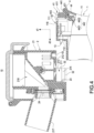
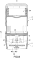
FIG. 5 is the first assembled cross-sectional view of the quick-release nebulizer of the disclosure; -
FIG. 6 is the second assembled cross-sectional view of the quick-release nebulizer of the disclosure; -
FIG. 7 is the third assembled cross-sectional view of the quick-release nebulizer of the disclosure; -
FIG. 8 is the fourth assembled cross-sectional view of the quick-release nebulizer of the disclosure; -
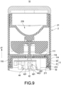
FIG. 9 is the fifth assembled cross-sectional view of the quick-release nebulizer of the disclosure; and -
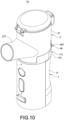
FIG. 10 is a perspective assembled view of the quick-release nebulizer of the disclosure. - The technical contents of this disclosure will become apparent with the detailed description of embodiments accompanied with the illustration of related drawings as follows. It is intended that the embodiments and drawings disclosed herein are to be considered illustrative rather than restrictive.
- Please refer to
FIGS 1-10 . The disclosure provides a quick-release nebulizer. Thenebulizer 10 includes amain body 1, a sprayinghead 2 and anengagement structure 4. - As shown in
FIGS. 1-10 , themain body 1 includes abody 11, apower assembly 12 received in thebody 11 and a firstconductive member 13 electrically connected to thepower assembly 12. Thebody 11 defines an axial direction d1 and a radial direction d2. In the embodiment, thepower assembly 12 includes a circuit board and a battery, and the firstconductive member 13 includes multiple pogo pins, but not limited to these. - In addition, the top of the
body 11 is protruded with ablock 111. Theblock 111 has afront side 112, arear side 113, aleft side 114, aright side 115 and atop side 116. The firstconductive member 13 is installed on thefront side 112. - As shown in
FIGS. 1 ,2 and4-10 , the sprayinghead 2 includes a sprayingseat 21 assembled to (assemblable with) or disassembled from (detachable with) thebody 11 along the radial direction d2. The bottom and the outer periphery of the sprayingseat 21 are formed with arecess 211. Therecess 211 has aninner bottom 212 and a U-shapedinner sidewall 213 disposed on a side of theinner bottom 212. - In detail, as shown in
FIGS 1-3 and9 , the quick-release nebulizer 10 of the disclosure further includes a slidingrail structure 3. The slidingrail structure 3 includes one ormore sliders 31 formed on either one of thebody 11 and the sprayingseat 21 and one or multiple pairs ofrails 32 formed on the other one of thebody 11 and the sprayingseat 21. - In the embodiment, the
sliders 31 are two in number, and therails 32 are two pairs in number, but not limited to these. The twosliders 31 are formed by protruding from theleft side 114 and theright side 115 of theblock 111. Two sides of the U-shapedinner sidewall 213 are formed with tworail grooves 214 along the radial direction d2. The U-shapedinner sidewall 213 is formed with each pair ofrails 32 corresponding to the upper side and the lower side of eachrail groove 214 so that each pair ofrails 32 is arranged along the radial direction d2 and in a top-and-bottom configuration. Eachslider 31 is slidable and stopped between each pair ofrails 32 so as to make the sprayingseat 21 be able to be assembled to or disassembled from thebody 11 along the radial direction d2. - In addition, the spraying
head 2 further includes a secondconductive member 22 and a no-water detection probe 23. The secondconductive member 22 is installed on the U-shapedinner sidewall 213 and abuts against the firstconductive member 13. Thepower assembly 12 transmits electricity to the no-water detection probe 23 only via the firstconductive member 13. The secondconductive member 22 in the embodiment includes, but not limited to, multiple conductive terminals. - Also, the outside of the spraying
seat 21 is extended with anozzle 217 and the inside thereof is disposed with anagent chamber 218 communicating with thenozzle 217. The sprayinghead 2 further includes anebulizing sheet 24 installed at the junction between thenozzle 217 and theagent chamber 218. An end of the no-water detection probe 23 stretches in theagent chamber 218 and is arranged corresponding to thenebulizing sheet 24. Thenebulizing sheet 24 is electrically connected with the secondconductive member 22. Thepower assembly 12 transmits electricity to thenebulizing sheet 24 via the firstconductive member 13 and the secondconductive member 22. The no-water detection probe 23 is used to detect if liquid exists after being electrified. Thenebulizing sheet 24 vibrates after being electrified to nebulize liquid in theagent chamber 218 and allows the nebulized liquid to pass through for being ejected through thenozzle 217. - As shown in
FIGS. 1-10 , theengagement structure 4 includes anotch 41 formed on one of thebody 11 and the sprayingseat 21, a T-shapedtrench 42 formed on an inner wall of thenotch 41 along the axial direction d1, an engagingtrench 43 formed on the other one of thebody 11 and the sprayingseat 21 and arranged corresponding to thenotch 41, and amovable member 44 movably received in thenotch 41. - In addition, a side of the
movable member 44 is extended with ahandle 441 exposed from thenotch 41, another side thereof is extended with a T-shapedblock 442 slidably received in the T-shapedtrench 42, and still another side thereof is protruded with anengaging block 443 along the axial direction d1, which may be embedded in or separated from the engagingtrench 43. - Further, the T-shaped
block 442 has ahead portion 4421 and arod portion 4422 connected between thehead portion 4421 and themovable member 44. The inner wall of the T-shapedtrench 42 is extended with tworesistant bumps 421 that are frictional with therod portion 4422. - Also, the
notch 41 of the embodiment is formed by indenting therear side 113 and thetop side 116. Thenotch 41 has anopening 411 formed on therear side 113 and aninner end face 412 corresponding to theopening 411. The T-shapedtrench 42 is formed by indenting theinner end face 412 and thetop side 116. The engagingtrench 43 is formed by indenting theinner bottom 212. Thehandle 441 is exposed from theopening 411. - In detail, when the
engaging block 443 is embedded in the engagingtrench 43, therod portion 4422 goes up over the tworesistant bumps 421 and rubs the tworesistant bumps 421 to transmit a hand-operated resistance. After that, the tworesistant bumps 421 abut against the bottom edge of therod portion 4422 to temporarily lock the position of themovable member 44 until a user downward pushes thehandle 441 to move therod portion 4422 to go down over the tworesistant bumps 421 so as to release the position of themovable member 44 to make theengaging block 443 smoothly disengage from the engagingtrench 43. - As shown in
FIGS. 1-10 , when using the quick-release nebulizer 10 of the disclosure, the sprayingseat 21 is assembled to thebody 11 through the slidingrail structure 3 along the radial direction d2 first, and then thehandle 441 is pushed upward along the axial direction d1 to drive the wholemovable member 44 to move upward so as to make theengaging block 443 be embedded in the engagingtrench 43 to lock the sprayingseat 21. As a result, the sprayinghead 2 may be rapidly assembled to themain body 1. On the contrary, thehandle 441 is pushed downward along the axial direction d1 to drive the wholemovable member 44 to move downward so as to make theengaging block 443 disengage from the engagingtrench 43 to release the sprayingseat 21, and then the sprayingseat 21 is removed from thebody 11 through the slidingrail structure 3 along the radial direction d2. As a result, the sprayinghead 2 may be rapidly disassembled from themain body 1. Therefore, the quick-release nebulizer 10 has the function of conveniently and rapidly assembling and disassembling the sprayinghead 2.
Claims (10)
- A nebulizer comprising:a main body (1), comprising a body (11), and the body (11) defining an axial direction (d1) and a radial direction (d2);a spraying head (2), comprising a spraying seat (21) assembled to or disassembled from the body (11) along the radial direction (d2); andan engagement structure (4), comprising a notch (41) disposed on one of the body (11) and the spraying seat (21), a T-shaped trench (42) disposed on an inner wall of the notch (41) along the axial direction (d1), an engaging trench (43) disposed on another one of the body (11) and the spraying seat (21) and arranged corresponding to the notch (41), and a movable member (44) received in the notch (41), wherein a side of the movable member (44) is extended with a handle (441) exposed from the notch (41), another side of the movable member (44) is extended with a T-shaped block (442) slidably received in the T-shaped trench (42), and still another side of the movable member (44) is protruded with an engaging block (443) embedded in or separated from the engaging trench (43) along the axial direction.
- The nebulizer of claim 1, wherein the T-shaped block (442) comprises a head portion (4421) and a rod portion (4422) connected between the head portion (4421) and the movable member (44), and an inner wall of the T-shaped trench (42) is extended with two resistant bumps (421) being frictional with the rod portion (4422).
- The nebulizer of claim 2, further comprising a sliding rail structure (3), wherein the sliding rail structure (3) comprises at least one slider (31) disposed on either one of the body (11) and the spraying seat (21) and at least one pair of rails (32) disposed on another one of the body (11) and the spraying seat (21), the at least one pair of rails (32) is arranged along the radial direction (d2) and in a top-and-bottom configuration, and the at least one slider (31) is slidable and stopped between the at least one pair of rails (32).
- The nebulizer of claim 3, wherein a top of the body (11) is protruded with a block (111), the block (111) comprises a rear side (113), a left side (114), a right side (115) and a top side (116), the slider (31) is two in number, the two sliders (31) protrude from the left side (114) and the right side (115), and the notch (41) is indented on the rear side (113) and the top side (116).
- The nebulizer of claim 4, wherein the notch (41) comprises an opening (411) defined on the rear side (113) and an inner end face (412) corresponding to the opening (411), the T-shaped trench (42) is indented on the inner end face (412) and the top side (116), and the handle (441) is exposed from the opening (411).
- The nebulizer of claim 4, wherein a bottom and an outer periphery of the spraying seat (21) are disposed with a recess (211), the recess (211) comprises an inner bottom (212) and a U-shaped inner sidewall (213) disposed on a side of the inner bottom (212), the engaging trench (43) is indented on the inner bottom (212), and the two resistant bumps (421) abut against a bottom edge of the rod portion (4422) when the engaging block (443) is embedded in the engaging trench (43).
- The nebulizer of claim 6, wherein the rails (32) are two pairs in number, two sides of the U-shaped inner sidewall (213) are disposed with two rail grooves (214) along the radial direction (d2), and each pair of rails (32) is disposed on an upper side and a lower side of each rail groove (214) correspondingly.
- The nebulizer of claim 6, wherein the block (111) comprises a front side (112), the main body (1) comprises a power assembly (12) received in the body (11) and a first conductive member (13) installed on the front side (112) and electrically connected to the power assembly (12).
- The nebulizer of claim 8, wherein an outside of the spraying seat (21) is extended with a nozzle (217) and an inside of the spraying seat (21) is disposed with an agent chamber (218) communicating with the nozzle (217), and the spraying head (2) further comprises a nebulizing sheet (24) installed at a junction between the nozzle (217) and the agent chamber (218).
- The nebulizer of claim 9, wherein the spraying head (2) further comprises a second conductive member (22) and a no-water detection probe (23), the second conductive member (22) is installed on the U-shaped inner sidewall (213) and abuts against the first conductive member (13), an end of the no-water detection probe (23) stretches in the agent chamber (218) and is arranged corresponding to the nebulizing sheet (24), and the nebulizing sheet (24) is electrically connected with the second conductive member (22).
Priority Applications (1)
| Application Number | Priority Date | Filing Date | Title |
|---|---|---|---|
| EP22176697.5A EP4285970B1 (en) | 2022-06-01 | 2022-06-01 | Quick-release nebulizer |
Applications Claiming Priority (1)
| Application Number | Priority Date | Filing Date | Title |
|---|---|---|---|
| EP22176697.5A EP4285970B1 (en) | 2022-06-01 | 2022-06-01 | Quick-release nebulizer |
Publications (3)
| Publication Number | Publication Date |
|---|---|
| EP4285970A1 EP4285970A1 (en) | 2023-12-06 |
| EP4285970C0 EP4285970C0 (en) | 2024-08-28 |
| EP4285970B1 true EP4285970B1 (en) | 2024-08-28 |
Family
ID=81940567
Family Applications (1)
| Application Number | Title | Priority Date | Filing Date |
|---|---|---|---|
| EP22176697.5A Active EP4285970B1 (en) | 2022-06-01 | 2022-06-01 | Quick-release nebulizer |
Country Status (1)
| Country | Link |
|---|---|
| EP (1) | EP4285970B1 (en) |
Family Cites Families (5)
| Publication number | Priority date | Publication date | Assignee | Title |
|---|---|---|---|---|
| EP3103496B1 (en) * | 2015-06-11 | 2018-08-15 | Delta Electronics, Inc. | Nebulization system |
| JP6686682B2 (en) * | 2016-05-09 | 2020-04-22 | オムロンヘルスケア株式会社 | Mesh type nebulizer and replacement parts |
| CN109091729B (en) * | 2017-06-20 | 2021-02-02 | 台达电子工业股份有限公司 | Nebulizer with push-on medicine cup |
| CN111956917B (en) * | 2020-08-18 | 2022-04-01 | 深圳市贝格美科技有限公司 | Multifunctional ultrasonic atomizer |
| TWI761074B (en) * | 2021-02-09 | 2022-04-11 | 心誠鎂行動醫電股份有限公司 | Nebulizer |
-
2022
- 2022-06-01 EP EP22176697.5A patent/EP4285970B1/en active Active
Also Published As
| Publication number | Publication date |
|---|---|
| EP4285970C0 (en) | 2024-08-28 |
| EP4285970A1 (en) | 2023-12-06 |
Similar Documents
| Publication | Publication Date | Title |
|---|---|---|
| US12374843B2 (en) | Pogo pin connector | |
| US12263297B2 (en) | Quick-release nebulizer | |
| US10105511B2 (en) | Respiratory humidifier | |
| US12491041B2 (en) | Medical device and storage box for medical article | |
| JP7776635B2 (en) | aerosol generator | |
| US8113849B2 (en) | Docking system for use with a mobile medication cart | |
| JP2004538072A (en) | Guide tabs and slides incorporating guide tabs | |
| TWI642454B (en) | Nebulizer having a push-type cup | |
| EP4285970A1 (en) | Quick-release nebulizer | |
| CN117180564B (en) | Counter with locking mechanism and sprayer comprising counter | |
| CN220090199U (en) | A water tank and ventilator for ventilator | |
| CN218219138U (en) | Atomizer and atomizing equipment convenient to dismantle | |
| CN214505324U (en) | Electronic pen key assembly and electronic pen | |
| CN116370779B (en) | A water tank for a ventilator and a ventilator | |
| CN221106642U (en) | Inferior valve subassembly and atomizing device | |
| CN217409482U (en) | Quick release atomizer | |
| US8619032B2 (en) | Mouse structure with retracting function | |
| TWM630765U (en) | Quick release atomizer | |
| CN216568350U (en) | Atomizer | |
| CN220000751U (en) | Air inlet assembly and electronic atomization device | |
| CN221556676U (en) | Detachable massager | |
| CN209807149U (en) | Electronic cigarette | |
| CN220365825U (en) | Isolation plate buckle unlocking mechanism suitable for endoscope transmission device | |
| CN222507878U (en) | Battery cover plate locking structure and telemetering monitoring equipment | |
| CN223787155U (en) | Heating base and atomizing device |
Legal Events
| Date | Code | Title | Description |
|---|---|---|---|
| PUAI | Public reference made under article 153(3) epc to a published international application that has entered the european phase |
Free format text: ORIGINAL CODE: 0009012 |
|
| STAA | Information on the status of an ep patent application or granted ep patent |
Free format text: STATUS: REQUEST FOR EXAMINATION WAS MADE |
|
| 17P | Request for examination filed |
Effective date: 20230108 |
|
| AK | Designated contracting states |
Kind code of ref document: A1 Designated state(s): AL AT BE BG CH CY CZ DE DK EE ES FI FR GB GR HR HU IE IS IT LI LT LU LV MC MK MT NL NO PL PT RO RS SE SI SK SM TR |
|
| GRAP | Despatch of communication of intention to grant a patent |
Free format text: ORIGINAL CODE: EPIDOSNIGR1 |
|
| STAA | Information on the status of an ep patent application or granted ep patent |
Free format text: STATUS: GRANT OF PATENT IS INTENDED |
|
| GRAS | Grant fee paid |
Free format text: ORIGINAL CODE: EPIDOSNIGR3 |
|
| RIC1 | Information provided on ipc code assigned before grant |
Ipc: A61M 15/00 20060101ALI20240228BHEP Ipc: A61M 11/00 20060101AFI20240228BHEP |
|
| INTG | Intention to grant announced |
Effective date: 20240315 |
|
| GRAA | (expected) grant |
Free format text: ORIGINAL CODE: 0009210 |
|
| STAA | Information on the status of an ep patent application or granted ep patent |
Free format text: STATUS: THE PATENT HAS BEEN GRANTED |
|
| AK | Designated contracting states |
Kind code of ref document: B1 Designated state(s): AL AT BE BG CH CY CZ DE DK EE ES FI FR GB GR HR HU IE IS IT LI LT LU LV MC MK MT NL NO PL PT RO RS SE SI SK SM TR |
|
| REG | Reference to a national code |
Ref country code: CH Ref legal event code: EP |
|
| REG | Reference to a national code |
Ref country code: DE Ref legal event code: R096 Ref document number: 602022005602 Country of ref document: DE |
|
| REG | Reference to a national code |
Ref country code: IE Ref legal event code: FG4D |
|
| U01 | Request for unitary effect filed |
Effective date: 20240828 |
|
| U07 | Unitary effect registered |
Designated state(s): AT BE BG DE DK EE FI FR IT LT LU LV MT NL PT RO SE SI Effective date: 20240905 |
|
| PG25 | Lapsed in a contracting state [announced via postgrant information from national office to epo] |
Ref country code: NO Free format text: LAPSE BECAUSE OF FAILURE TO SUBMIT A TRANSLATION OF THE DESCRIPTION OR TO PAY THE FEE WITHIN THE PRESCRIBED TIME-LIMIT Effective date: 20241128 |
|
| PG25 | Lapsed in a contracting state [announced via postgrant information from national office to epo] |
Ref country code: GR Free format text: LAPSE BECAUSE OF FAILURE TO SUBMIT A TRANSLATION OF THE DESCRIPTION OR TO PAY THE FEE WITHIN THE PRESCRIBED TIME-LIMIT Effective date: 20241129 Ref country code: PL Free format text: LAPSE BECAUSE OF FAILURE TO SUBMIT A TRANSLATION OF THE DESCRIPTION OR TO PAY THE FEE WITHIN THE PRESCRIBED TIME-LIMIT Effective date: 20240828 |
|
| PG25 | Lapsed in a contracting state [announced via postgrant information from national office to epo] |
Ref country code: IS Free format text: LAPSE BECAUSE OF FAILURE TO SUBMIT A TRANSLATION OF THE DESCRIPTION OR TO PAY THE FEE WITHIN THE PRESCRIBED TIME-LIMIT Effective date: 20241228 |
|
| PG25 | Lapsed in a contracting state [announced via postgrant information from national office to epo] |
Ref country code: HR Free format text: LAPSE BECAUSE OF FAILURE TO SUBMIT A TRANSLATION OF THE DESCRIPTION OR TO PAY THE FEE WITHIN THE PRESCRIBED TIME-LIMIT Effective date: 20240828 |
|
| PG25 | Lapsed in a contracting state [announced via postgrant information from national office to epo] |
Ref country code: RS Free format text: LAPSE BECAUSE OF FAILURE TO SUBMIT A TRANSLATION OF THE DESCRIPTION OR TO PAY THE FEE WITHIN THE PRESCRIBED TIME-LIMIT Effective date: 20241128 Ref country code: ES Free format text: LAPSE BECAUSE OF FAILURE TO SUBMIT A TRANSLATION OF THE DESCRIPTION OR TO PAY THE FEE WITHIN THE PRESCRIBED TIME-LIMIT Effective date: 20240828 |
|
| PG25 | Lapsed in a contracting state [announced via postgrant information from national office to epo] |
Ref country code: RS Free format text: LAPSE BECAUSE OF FAILURE TO SUBMIT A TRANSLATION OF THE DESCRIPTION OR TO PAY THE FEE WITHIN THE PRESCRIBED TIME-LIMIT Effective date: 20241128 Ref country code: PL Free format text: LAPSE BECAUSE OF FAILURE TO SUBMIT A TRANSLATION OF THE DESCRIPTION OR TO PAY THE FEE WITHIN THE PRESCRIBED TIME-LIMIT Effective date: 20240828 Ref country code: NO Free format text: LAPSE BECAUSE OF FAILURE TO SUBMIT A TRANSLATION OF THE DESCRIPTION OR TO PAY THE FEE WITHIN THE PRESCRIBED TIME-LIMIT Effective date: 20241128 Ref country code: IS Free format text: LAPSE BECAUSE OF FAILURE TO SUBMIT A TRANSLATION OF THE DESCRIPTION OR TO PAY THE FEE WITHIN THE PRESCRIBED TIME-LIMIT Effective date: 20241228 Ref country code: HR Free format text: LAPSE BECAUSE OF FAILURE TO SUBMIT A TRANSLATION OF THE DESCRIPTION OR TO PAY THE FEE WITHIN THE PRESCRIBED TIME-LIMIT Effective date: 20240828 Ref country code: GR Free format text: LAPSE BECAUSE OF FAILURE TO SUBMIT A TRANSLATION OF THE DESCRIPTION OR TO PAY THE FEE WITHIN THE PRESCRIBED TIME-LIMIT Effective date: 20241129 Ref country code: ES Free format text: LAPSE BECAUSE OF FAILURE TO SUBMIT A TRANSLATION OF THE DESCRIPTION OR TO PAY THE FEE WITHIN THE PRESCRIBED TIME-LIMIT Effective date: 20240828 |
|
| PG25 | Lapsed in a contracting state [announced via postgrant information from national office to epo] |
Ref country code: SM Free format text: LAPSE BECAUSE OF FAILURE TO SUBMIT A TRANSLATION OF THE DESCRIPTION OR TO PAY THE FEE WITHIN THE PRESCRIBED TIME-LIMIT Effective date: 20240828 |
|
| PG25 | Lapsed in a contracting state [announced via postgrant information from national office to epo] |
Ref country code: CZ Free format text: LAPSE BECAUSE OF FAILURE TO SUBMIT A TRANSLATION OF THE DESCRIPTION OR TO PAY THE FEE WITHIN THE PRESCRIBED TIME-LIMIT Effective date: 20240828 |
|
| PG25 | Lapsed in a contracting state [announced via postgrant information from national office to epo] |
Ref country code: SK Free format text: LAPSE BECAUSE OF FAILURE TO SUBMIT A TRANSLATION OF THE DESCRIPTION OR TO PAY THE FEE WITHIN THE PRESCRIBED TIME-LIMIT Effective date: 20240828 |
|
| PLBE | No opposition filed within time limit |
Free format text: ORIGINAL CODE: 0009261 |
|
| STAA | Information on the status of an ep patent application or granted ep patent |
Free format text: STATUS: NO OPPOSITION FILED WITHIN TIME LIMIT |
|
| 26N | No opposition filed |
Effective date: 20250530 |
|
| U20 | Renewal fee for the european patent with unitary effect paid |
Year of fee payment: 4 Effective date: 20250630 |
|
| REG | Reference to a national code |
Ref country code: CH Ref legal event code: H13 Free format text: ST27 STATUS EVENT CODE: U-0-0-H10-H13 (AS PROVIDED BY THE NATIONAL OFFICE) Effective date: 20260127 |
|
| PG25 | Lapsed in a contracting state [announced via postgrant information from national office to epo] |
Ref country code: MC Free format text: LAPSE BECAUSE OF FAILURE TO SUBMIT A TRANSLATION OF THE DESCRIPTION OR TO PAY THE FEE WITHIN THE PRESCRIBED TIME-LIMIT Effective date: 20240828 |
|
| PG25 | Lapsed in a contracting state [announced via postgrant information from national office to epo] |
Ref country code: IE Free format text: LAPSE BECAUSE OF NON-PAYMENT OF DUE FEES Effective date: 20250601 |
|
| PG25 | Lapsed in a contracting state [announced via postgrant information from national office to epo] |
Ref country code: CH Free format text: LAPSE BECAUSE OF NON-PAYMENT OF DUE FEES Effective date: 20250630 |