EP4285758A1 - Aerosol generating device - Google Patents
Aerosol generating device Download PDFInfo
- Publication number
- EP4285758A1 EP4285758A1 EP21922642.0A EP21922642A EP4285758A1 EP 4285758 A1 EP4285758 A1 EP 4285758A1 EP 21922642 A EP21922642 A EP 21922642A EP 4285758 A1 EP4285758 A1 EP 4285758A1
- Authority
- EP
- European Patent Office
- Prior art keywords
- aerosol
- sidewall
- heating
- airflow channel
- generating substrate
- Prior art date
- Legal status (The legal status is an assumption and is not a legal conclusion. Google has not performed a legal analysis and makes no representation as to the accuracy of the status listed.)
- Pending
Links
- 239000000443 aerosol Substances 0.000 title abstract description 13
- 238000010438 heat treatment Methods 0.000 claims abstract description 181
- 239000000758 substrate Substances 0.000 claims description 124
- 239000011159 matrix material Substances 0.000 abstract 3
- 239000000463 material Substances 0.000 description 10
- 239000002184 metal Substances 0.000 description 6
- 238000000034 method Methods 0.000 description 6
- 230000005674 electromagnetic induction Effects 0.000 description 5
- 239000000126 substance Substances 0.000 description 3
- 230000000694 effects Effects 0.000 description 2
- 238000005516 engineering process Methods 0.000 description 2
- 230000002093 peripheral effect Effects 0.000 description 2
- 244000025254 Cannabis sativa Species 0.000 description 1
- 239000000956 alloy Substances 0.000 description 1
- 229910045601 alloy Inorganic materials 0.000 description 1
- 230000009286 beneficial effect Effects 0.000 description 1
- 239000004020 conductor Substances 0.000 description 1
- 230000006698 induction Effects 0.000 description 1
- 230000001788 irregular Effects 0.000 description 1
- 238000013021 overheating Methods 0.000 description 1
Images


Classifications
-
- A—HUMAN NECESSITIES
- A24—TOBACCO; CIGARS; CIGARETTES; SIMULATED SMOKING DEVICES; SMOKERS' REQUISITES
- A24F—SMOKERS' REQUISITES; MATCH BOXES; SIMULATED SMOKING DEVICES
- A24F40/00—Electrically operated smoking devices; Component parts thereof; Manufacture thereof; Maintenance or testing thereof; Charging means specially adapted therefor
- A24F40/40—Constructional details, e.g. connection of cartridges and battery parts
- A24F40/48—Fluid transfer means, e.g. pumps
- A24F40/485—Valves; Apertures
-
- A—HUMAN NECESSITIES
- A24—TOBACCO; CIGARS; CIGARETTES; SIMULATED SMOKING DEVICES; SMOKERS' REQUISITES
- A24F—SMOKERS' REQUISITES; MATCH BOXES; SIMULATED SMOKING DEVICES
- A24F40/00—Electrically operated smoking devices; Component parts thereof; Manufacture thereof; Maintenance or testing thereof; Charging means specially adapted therefor
- A24F40/40—Constructional details, e.g. connection of cartridges and battery parts
- A24F40/46—Shape or structure of electric heating means
- A24F40/465—Shape or structure of electric heating means specially adapted for induction heating
-
- A—HUMAN NECESSITIES
- A24—TOBACCO; CIGARS; CIGARETTES; SIMULATED SMOKING DEVICES; SMOKERS' REQUISITES
- A24F—SMOKERS' REQUISITES; MATCH BOXES; SIMULATED SMOKING DEVICES
- A24F40/00—Electrically operated smoking devices; Component parts thereof; Manufacture thereof; Maintenance or testing thereof; Charging means specially adapted therefor
- A24F40/20—Devices using solid inhalable precursors
Definitions
- the present disclosure relates to the field of aerosol-generating technologies, and in particular, to an aerosol-generating device.
- the aerosol-generating device of the "heat-not-burn” type generates aerosols by heating and baking different forms of aerosol-generating substrates (such as grass leaf materials), and transmits the aerosol to a user for inhalation.
- the aerosol-generating substrate is heated only at a lower temperature (200°C-400°C), does not burn and does not generate an open flame, and effectively avoids generation of harmful substances caused by the aerosol-generating substrate.
- electromagnetic induction heating or resistive material heating is commonly used in the "heat-not-burn" aerosol-generating device.
- the electromagnetic induction heating is as follows: A coil is disposed around a heating member that contains the aerosol-generating substrate, the heating member heats up by means of electromagnetic induction, heat is conducted to the aerosol-generating substrate, and baking and heating are performed on the aerosol-generating substrate.
- the aerosol-generating substrate is usually formed into a close fit with the heating member for baking and heating.
- the heating member is able to reach a very high temperature at a moment, and the outer periphery of the aerosol-generating substrate that is in direct contact with the heating member is able to easily reach a high temperature.
- inner heat transfer efficiency of the aerosol-generating substrate is low, baking of the inner aerosol-generating substrate is insufficient, and temperature distribution of the inner and outer periphery of the aerosol-generating substrate is uneven.
- the aerosol-generating device is able to resolve the problem that the inner and outer peripheral temperatures are uneven when the aerosol-generating substrate is heated.
- the aerosol-generating device includes a heating base and a heating member.
- the heating base has a heating cavity; and the heating member is configured to accommodate and heat an aerosol-generating substrate, where the heating member is disposed in the heating cavity; where the heating member includes a first sidewall, and a first airflow channel is formed between the first sidewall and the inner surface of the heating cavity; and a protrusion is disposed on the inner surface of the first sidewall, the protrusion makes a second airflow channel formed between the first sidewall and the aerosol-generating substrate, and both the first airflow channel and the second airflow channel are led from the outside of the aerosol-generating device to the bottom of the heating cavity.
- a proportion of an area of the surface of the protrusion for contacting the aerosol-generating substrate to an area of the inner surface of the first sidewall is 5%-15%.
- the maximum height of the protrusion is 2 mm-5 mm.
- the first sidewall is disposed in a ring shape; and the protrusion is spirally disposed on the inner surface of the first sidewall; or a plurality of strip-shaped protrusions are disposed on the inner surface of the first sidewall at intervals in the circumferential direction; or a plurality of arcuate protrusions are disposed on the inner surface of the first sidewall at intervals in the circumferential direction; or a plurality of dotted protrusions are distributed in an array on the inner surface of the first sidewall; or a plurality of annular protrusions are disposed on the inner surface of the first sidewall at intervals in the axial direction, and each annular protrusion has a groove or a through hole.
- a part of the first sidewall portion is concave to form the protrusion.
- the first sidewall is disposed in a ring shape, and the heating member is disposed coaxially with the heating base.
- the heating base includes a second sidewall, a first limiting member is disposed between the first sidewall and the second sidewall, and the first limiting member spaces the first sidewall from the second sidewall to form the first airflow channel between the first sidewall and the inner surface of the heating cavity.
- the outer surface of the first sidewall is protruded to form the first limiting member; and/or the inner surface of the second sidewall is protruded to form the first limiting member.
- the heating base includes a second sidewall and a bottom wall, and the second sidewall and the bottom wall surround to form the heating cavity; and a third airflow channel is formed between the bottom wall and the aerosol-generating substrate, and the third airflow channel communicates with the first airflow channel and the second airflow channel.
- a first limiting member is disposed between the first sidewall and the second sidewall, and the first limiting member is configured to limit the heating member for the third airflow channel to communicate with the first airflow channel.
- the first sidewall abuts against the bottom wall, and one end of the first sidewall close to the bottom wall has an opening for the third airflow channel to communicate with the first airflow channel.
- the bottom wall or the first sidewall or the second sidewall is provided with a second limiting member; and the second limiting member spaces the aerosol-generating substrate from the bottom wall to form the third airflow channel.
- a first airflow channel and a second airflow channel are formed on two sides of a heating member.
- a protrusion in the second airflow channel changes a heat transfer mode of the heating member for heating the aerosol-generating substrate from heat conduction to a combination of heat conduction and heat convection, in which heat convection takes a main heat transfer manner.
- Heat transfer efficiency of heat convection is lower than heat transfer efficiency of heat conduction, and therefore, the heat transfer rate of the heat from the heating member to the outer periphery of the aerosol-generating substrate is able to be effectively slowed down.
- a cold airflow passes through the first airflow channel and the second airflow channel, such that the heating rate of air in the first airflow channel and the second airflow channel is able to be slower, and the heat transfer rate of the heating member to the outer periphery of the aerosol-generating substrate is close to the heat transfer rate of the outer periphery of the aerosol-generating substrate to the inside of the aerosol-generating substrate. Therefore, the temperature difference between the inner and outer periphery of the aerosol-generating substrate is effectively reduced, thereby resolving the problem of uneven temperature distribution between the inner and outer periphery of the aerosol-generating substrate during heating.
- first”, “second”, and “third” in the present disclosure are merely intended for a purpose of description, and shall not be understood as an indication or implication of relative importance or implicit indication of the number of indicated technical features. Therefore, features defining “first”, “second”, and “third” may explicitly or implicitly include at least one feature.
- “plurality of” means at least two, such as two and three unless it is specifically defined otherwise. All directional indications (for example, up, down, left, right, front, back%) in the embodiments of the present disclosure are only used for explaining relative position relationships, movement situations, or the like between the various components in a specific posture (as shown in the accompanying drawings). If the specific posture changes, the directional indications change accordingly.
- the terms “include”, “have”, and any variant thereof are intended to cover a non-exclusive inclusion.
- a process, method, system, product, or device that includes a series of steps or units is not limited to the listed steps or units, but further optionally includes a step or unit that is not listed, or further optionally includes another step or component that is intrinsic to the process, method, product, or device.
- Embodiments mentioned in the specification means that particular features, structures, or characteristics described with reference to the embodiments may be included in at least one embodiment of the present disclosure.
- a term appearing at different positions of this specification may not refer to the same embodiment or an independent or alternative embodiment that is mutually exclusive with some embodiments.
- a person skilled in the art explicitly or implicitly understands that the embodiments described in the specification may be combined with other embodiments.
- an aerosol-generating substrate has a housing.
- the outside is provided with a paper package, but to make the description of the embodiments more simplified, an aerosol-generating substrate described below generally refers to an aerosol-generating substrate including a housing.
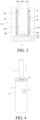
- FIG. 1 is a structural schematic view of an aerosol-generating device 10 according to the present disclosure
- FIG. 2 is a cross-sectional structural schematic view of the aerosol-generating device 10 shown in FIG. 1
- FIG. 3 is an enlarged structural schematic view of part A shown in FIG. 2
- FIG. 4 is a structural schematic view of an aerosol-generating device 10 and an aerosol-generating substrate 11 assembled together.
- the aerosol-generating device 10 is provided.
- the aerosol-generating device 10 may be configured to heat and bake the aerosol-generating substrate 11 and generate an aerosol for a user to inhale.
- the aerosol-generating device 10 includes a housing 12 and a heating switch 13.
- the heating switch 13 is disposed on the outer surface of the housing 12, and is configured to control on and off of the aerosol-generating device 10.
- Various components of the aerosol-generating device 10 are disposed in the housing 12.
- the shape of the housing 12 is cylindrical. In other embodiments, the housing 12 may also be other shapes.
- the housing 12 may be made of the same material, or may be made of multiple materials.
- the housing 12 includes a plastic outer layer and a metal inner layer, and the user is only able to contact the plastic outer layer when using it.
- Heat generated inside the aerosol-generating device 10 is evenly distributed in the metal inner layer due to the property of rapid heat conduction of the metal, so as to prevent scalding hands of the user as a result of the heated plastic outer layer being touched by the user, and is able to further prevent softening of the plastic outer layer.
- the aerosol-generating device 10 further includes an atomizer 14, a battery assembly 15, and a controller 16.
- the atomizer 14 is electrically connected to the battery assembly 15.
- a top of the housing 12 has a first opening 121
- the inside of the housing 12 has a mounting cavity 122
- both the atomizer 14 and the battery assembly 15 are disposed in the mounting cavity 122
- the atomizer 14 is disposed on one side of the battery assembly 15 close to the first opening 121.
- the atomizer 14 is configured to heat and bake the aerosol-generating substrate 11 and generate an aerosol
- the battery assembly 15 is configured to provide a power supply for the atomizer 14.
- the atomizer 14 includes a heating base 17, a coil 18, and a heating member 19.
- the controller 16 is disposed on one side of the battery assembly 15 close to the first opening 121, and the controller 16 is electrically connected to the coil 18, the heating switch 13, and the battery assembly 15.
- the controller 16 is configured to control start and stop of heating of the coil 18 and the heating member 19 by means of electromagnetic induction, and is able to control parameters such as a heating power and a temperature.
- the heating switch 13 of the housing 12 may be pressed.
- the battery assembly 15 is controlled to supply power to the coil 18, such that the coil 18 and the heating member 19 heat the aerosol-generating substrate by means of electromagnetical induction.
- the controller 16 When the user presses the heating switch 13 of the housing 12 again, the controller 16 receives a request of stop using from the user, and controls the battery assembly 15 to stop supplying power to the coil 18, then the coil 18 stops working.
- the controller 16 further has other functions, and details are not described herein.
- the heating base 17 is configured to fasten the aerosol-generating substrate 11.
- the heating base 17 is disposed at one end of the mounting cavity 122 close to the first opening 121, and the heating base 17 has a bottom wall 171 and a second sidewall 172.
- the second sidewall 172 of the heating base 17 is arranged in a ring shape and is shaped as a cylinder, the second sidewall 172 is disposed at one end of the bottom wall 171 close to the first opening 121, and the second sidewall 172 and the bottom wall 171 of the heating base 17 surround to form the heating cavity 173.
- the thickness of the bottom wall 171 is greater than the thickness of the second sidewall 172, such that the structural strength of the heating base 17 is higher.
- the second sidewall 172 and the bottom wall 171 are integrally formed, and the material of the second sidewall 172 and the bottom wall 171 may be a thermally conductive material such as a metal or an alloy.
- a top of the second sidewall 172 of the heating base 17 abuts against a top of the housing 12, and the heating base 17 is coaxially disposed with the housing 12.
- One end of the second sidewall 172 close to the first opening 121 has a second opening 174, and the caliber of the second opening 174 is greater than or equal to the caliber of the first opening 121. Therefore, the heating base 17 separates the mounting cavity 122 from the heating cavity 173, and the heating cavity 173 communicates with the outside of the aerosol-generating device 10 through the second opening 174 and the first opening 121.
- the caliber of the second opening 174 is the same as the caliber of the first opening 121 and less than the inner diameter of the second sidewall 172, and shapes of both the second opening 174 and the first opening 121 are circular.
- the heating base 17 is not limited to the structure described in the present embodiment.
- the coil 18 is configured to heat the aerosol-generating substrate 11.
- the coil 18 is sleeved on the outer periphery of the second sidewall 172 of the heating base 17, so as to heat the aerosol-generating substrate 11 in the heating member 19.
- the coil 18 is a spirally wound coil, and a changing magnetic field is generated after the coil is energized, forming an eddy current which penetrates the metal heating member 19, such that the metal heating member 19 heats up and heats the aerosol-generating substrate 11.
- other heating manners for example, a resistance wire, may be used to heat the aerosol-generating substrate 11.
- the heating member 19 is disposed in the heating cavity 173.
- the heating member 19 includes a first sidewall 191. Further, the first sidewall 191 of the heating member 19 is annularly arranged, and one end of the first sidewall 191 close to the second opening 174 has a third opening 192. Therefore, the inside of the heating member 19 communicates with the heating cavity 173, and communicates with the outside of the aerosol-generating device 10.
- the heating member 19 is configured to accommodate and heat the aerosol-generating substrate 11, and the aerosol-generating substrate 11 may be disposed inside the heating member 19.
- the aerosol-generating substrate 11 is inserted from the first opening 121 of the aerosol-generating device 10, and is disposed inside a heat conductive body after successively passing through the second opening 174 of the heating base 17 and the third opening 192 of the heating member 19.
- the shape of the heating member 19 may be cylindrical, or certainly, may be other shapes, such as a cylinder-like shape or a cube.
- the heating member 19 is coaxial with the heating base 17. Therefore, the coil 18 is able to evenly heat the outer periphery of the first sidewall 191, and is further able to evenly heat the outer periphery of the aerosol-generating substrate 11.
- FIG. 7 is a schematic view of a flow path of an airflow in the aerosol-generating device 10 according to the present disclosure.
- a protrusion 193 is provided on the inner surface of the first sidewall 191 of the heating member 19. A part of the surface of the protrusion 193 is in contact with the outer periphery of the aerosol-generating substrate 11, and heat is transferred to the aerosol-generating substrate 11 in a heat conduction manner.
- the protrusion 193 of the first sidewall 191 is able to form a gap between the aerosol-generating substrate 11 and the inner surface of the first sidewall 191, and form a second airflow channel 20.
- the second airflow channel 20 is led from the outside of the aerosol-generating device 10 to the bottom of the heating cavity 173, such that air flows from the third opening 192 into the second airflow channel 20, flows to the bottom of the heating cavity 173 through the second airflow channel 20, and finally flows to one end of the aerosol-generating substrate 11 away from the third opening 192.
- the airflow flows through the protrusion 193 on the first sidewall 191
- the airflow flows from two sides of the protrusion 193 to the bottom of the aerosol-generating substrate 11.
- the first airflow channel 21 is led from the outside of the aerosol-generating device 10 to the bottom of the heating cavity 173, such that air flows from the second opening 174 into the second airflow channel 20, flows to the bottom of the heating cavity 173 through the second airflow channel 20, and finally flows to one end of the aerosol-generating substrate 11 away from the third opening 192.
- the second airflow channel 20 and the protrusion 193 are disposed to change the heat transfer mode of the heating member 19 to the aerosol-generating substrate 11 from heat conduction to a combination of heat conduction and heat convection, and heat convection is the main heat transfer manner.
- Heat transfer efficiency of heat convection is lower than heat transfer efficiency of heat conduction, and therefore, a heat transfer rate of the heat from the heating member 19 to the outer periphery of the aerosol-generating substrate 11 is effectively slowed down. Therefore, the heat transfer rate of the heating member 19 to the outer periphery of the aerosol-generating substrate 11 is close to the heat transfer rate of the outer periphery of the aerosol-generating substrate 11 to the inside of the aerosol-generating substrate 11.
- the temperature difference between the inner and outer periphery of the aerosol-generating substrate 11 is effectively reduced, thereby resolving the problem of uneven temperature between the inner and outer periphery of the aerosol-generating substrate 11 during heating.
- the first airflow channel 21 and the second airflow channel 20 are disposed on two sides of the heating member 19, such that the heating rate of air in the first airflow channel 21 and in the second airflow channel 20 is slower.
- the airflow flows from the outside of the aerosol-generating device 10 through the first airflow channel 21 and the second airflow channel 20 to the bottom of the heating cavity 173, and heat in the first airflow channel 21 and the second airflow channel 20 is taken away, such that heat generated by the heating member 19 and heat radiated by the first sidewall 191 on the inner surface of the heating base 17 are reduced.
- the heat transfer rate of the heat to the outer periphery of the aerosol-generating substrate 11 is slower, the temperature difference between the outer periphery of the aerosol-generating substrate 11 and the inside of the aerosol-generating substrate 11 is smaller, and uniformity of temperature distribution between the inner periphery and the outer periphery of the aerosol-generating substrate 11 is better, thereby resolving the problem of uneven temperature between the inner and outer periphery of the aerosol-generating substrate during heating.
- the housing 12 of the aerosol-generating device 10 is able to be insulated.
- first airflow channel 21 and the second airflow channel 20 are disposed on two sides of the heating member 19, such that flow of the airflow in the heating cavity 173 is able to be increased, and the airflow may simultaneously flow from two sides of the first sidewall 191. Therefore, inhalation resistance inside the aerosol-generating device 10 is smaller, and the user inhales more easily when using the aerosol-generating device 10.
- the protrusion 193 is able to further reduce a contact area between the heating member 19 and the aerosol-generating substrate 11, and an aerosol condensate is less likely to adhere to the first sidewall 191, thereby reducing adhesion of stains on the heating member 19.
- the arrangement of the protrusion 193 is also able to reduce a contact area between the heating member 19 and the paper outer wall, so as to prevent the paper outer wall from being baked and pasted due to overheating, and prevent a pungent smell from forming, which improves user experience.
- the area of the surface of the protrusion 193 in contact with the aerosol-generating substrate 11 to the area of the inner surface of the first sidewall 191 is in a ratio of 5%-15%.
- the ratio may be 5%, 10%, or 15%.
- the surface of the protrusion 193 in contact with the aerosol-generating substrate 11 means: the surface of one end of the protrusion 193 in contact with the surface of the aerosol-generating substrate 11 when the aerosol-generating substrate 11 is disposed in the heating member 19.
- the heat transfer rate of the heating member 19 toward the outer periphery of the aerosol-generating substrate 11 is gradually similar to the heat transfer rate of the outer periphery of the aerosol-generating substrate 11 toward the inside of the aerosol-generating substrate 11, and the temperature difference between the inner and outer periphery of the aerosol-generating substrate 11 is reduced, thereby effectively resolving the problem of uneven temperature distribution on the inner periphery and outer periphery of the aerosol-generating substrate 11 during heating.
- the heat transfer rate inside the aerosol-generating substrate 11 is greater than the heat transfer rate between the heating member 19 and the outer periphery of the aerosol-generating substrate 11, and the temperature difference between the inside and outside of the aerosol-generating substrate 11 tends to be 0 after heating for a period of time, and the inner and outer periphery temperature are more evenly distributed.
- the area ratio of the contact surface to the inner surface of the first sidewall 191 may not be too high or too low, and when the area ratio is too high, the proportion of heat convection in the common heat transfer manner is reduced, and the heat transfer rate of the heat to the aerosol-generating substrate 11 is not able to be reduced. Too low an area ratio makes the proportion of heat conduction too low and the heating effect is not good.
- the protrusion 193 may be a bump, and the bump is disposed on the inner surface of the first sidewall 191.
- the material of the bump may be the same as the material of the first sidewall 191, and the bump and the first sidewall 191 are integrally formed.
- the bump may alternatively be made of a material different from the material of the first sidewall 191, and the bump may be made of a material with relatively poor heat conductivity. Therefore, when the heat is transferred from the protrusion 193 to the aerosol-generating substrate 11 in the heat conduction manner, As heat conductivity of the bump is relatively poor, the speed of heat conduction may be reduced, such that the heat transfer rate of the heating member 19 to the outer periphery of the aerosol-generating substrate 11 and the heat transfer rate of the outer periphery of the aerosol-generating substrate 11 to the inside of the aerosol-generating substrate 11 are closer to each other. Therefore, the temperature difference between the inner and outer periphery of the aerosol-generating substrate 11 is effectively reduced, and the temperature of the inner and outer periphery of the aerosol-generating substrate 11 is more uniform.
- the maximum height of the protrusion 193 is 2 mm-5 mm.
- the maximum height of the protrusion 193 refers to the maximum height at which the protrusion 193 protrudes relative to the inner surface of the first sidewall 191.
- the maximum height of the protrusion 193 may be adjusted to adjust the width of the gap between the heating member 19 and the aerosol-generating substrate 11, so as to control the size of the airflow in the second airflow channel 20, thereby achieving the effect of adjusting the inhalation resistance.
- protrusions 193, and one protrusion 193 may be spirally disposed on the inner surface of the first sidewall 191.
- a plurality of protrusions 193 may be circumferentially distributed on the inner surface of the first sidewall 191, and/or the plurality of protrusions 193 are axially distributed on the inner surface of the first sidewall 191.
- the plurality of protrusions 193 may be evenly distributed along the circumferential direction at intervals, and the plurality of protrusions 193 are in contact with the peripheral edge of the aerosol-generating substrate 11, so as to limit the aerosol-generating substrate 11.
- the shape of the protrusion 193 may be a regular shape, such as a strip shape, a dot shape, or a ring shape, or may be an irregular shape.
- four types of heating members 19 with different shapes and distributed protrusions 193 are shown in FIG. 8 to FIG. 11 .
- the protrusion 193 in FIG. 8 is strip-shaped, and the strip-shaped protrusion 193 extends from the third opening 192 to one end facing away from the third opening 192, that is, extends from the top of the first sidewall 191 to the bottom.
- the plurality of strip-shaped protrusions 193 are distributed on the inner surface of the first sidewall 191 at intervals in the circumferential direction. Specifically, the four strip-shaped protrusions 193 are evenly circumferentially distributed on the inner surface of the first sidewall 191.
- the extending direction of the strip-shaped protrusion 193 may be parallel to the axial direction of the heating member 19.
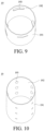
- the protrusion 193 in FIG. 9 is arcuate, one end of the arcuate protrusion 193 extends in the circumferential direction to another end, and a plurality of arcuate protrusions 193 are distributed on the inner surface of the first sidewall 191 at intervals in the circumferential direction. Specifically, the four arcuate protrusions 193 are evenly circumferentially distributed on the inner surface of the first sidewall 191.
- the distribution of the protrusions 193 shown in FIG. 9 may also be considered as an annular protrusion 193 being broken into four arcuate protrusions 193 in the circumferential direction.
- the plurality of annular protrusions 193 may be disposed at intervals in the axial direction of the heating member 19, and each annular protrusion 193 has a groove or a through hole, so as to form the second airflow channel 20.
- the protrusions 193 shown in FIG. 10 are dot-shaped, and the dot-shaped protrusions 193 are distributed in an array on the inner surface of the first sidewall 191. Specifically, twelve dot-shaped protrusions 193 are distributed in an array on the inner surface of the first sidewall 191. In some embodiments, the dot-shaped protrusions 193 may alternatively be irregularly distributed on the inner surface of the first sidewall 191.
- the plurality of dot-shaped protrusions 193 may be distributed in a plurality of rows, each row of dot-shaped protrusions 193 is arranged along the axial direction of the heating member 19, and the plurality of rows of dot-shaped protrusions 193 are disposed at intervals in the circumferential direction of the heating member 19.
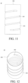
- the protrusions 193 shown in FIG. 11 and FIG. 12 are spirally shaped.
- FIG. 11 is a front view of the heating member 19 provided with the spirally shaped protrusions 193.
- FIG. 12 is a structural schematic view of the heating member 19 provided with the spirally shaped protrusions 193.
- the spiral protrusion 193 of the present embodiment is a non-closing ring, such that the second airflow channel 20 is able to be formed between the inner surface of the first sidewall 191 and the aerosol-generating substrate 11, and is led from the third opening 192 to one end of the aerosol-generating substrate 11 facing away from the third opening 192.
- the spiral protrusions 193 may alternatively be disconnected and axially distributed on the inner surface of the first sidewall 191.
- the shape and distribution of the protrusions 193 need to enable the second airflow channel 20 to be formed between the inner surface of the heating member 19 and the aerosol-generating substrate 11, and the second airflow channel 20 is led from the top of the heating member 19 to the bottom of the aerosol-generating substrate 11.
- the shape and distribution of the protrusions 193 are not limited to the foregoing manners, and may alternatively be in other manners.
- a first limiting member 22 is disposed between the outer surface of the first sidewall 191 and the inner surface of the second sidewall 172.
- the first limiting member 22 limits the heating member 19 to the inside of the heating cavity 173, such that the first airflow channel 21 is formed between the first sidewall 191 and the inner surface of the heating cavity 173.
- the first limiting member 22 is circumferentially sleeved on the outer surface of the first sidewall 191, such that there is a gap between the first sidewall 191 and the heating cavity 173, and the first airflow channel 21 is formed between the first sidewall 191 and the inner surface of the heating cavity 173.
- the first limiting member 22 has an air hole, and the air hole in the first limiting member 22 is able to enable an airflow to flow in from the second opening 174, and then flow through the first airflow channel 21 via the air hole in the first limiting member 22, and finally flow to the bottom of the aerosol-generating substrate 11.
- the quantity of the first limiting members 22 may be one or more.
- the first limiting member 22 may be a rubber ring, and the first limiting member 22 may be fastened between the heating base 17 and the heating member 19 in a close fitting and bonding manner.
- the first limiting member 22 is protruded on the outer surface of the heating member 19, and the first limiting member 22 and the outer surface of the heating member 19 are integrally formed.
- the first limiting member 22 is protruded on the inner surface of the heating cavity 173, and the first limiting member 22 and the inner surface of the heating cavity 173 are integrally formed.
- the first limiting member 22 is protruded on the inner surface of the heating cavity 173 or the outer surface of the heating member 19, the shape and distribution of the first limiting member 22 are the same as those in the above manners in which the protrusion 193 is disposed. That is, the protrusion 193 is disposed on the outer surface of the heating member 19 to form the first limiting member 22.
- the shape and distribution of the first limiting member 22 are not described herein again.
- a third airflow channel 23 is formed between the bottom wall 171 and the aerosol-generating substrate 11, and the third airflow channel 23 communicates with the first airflow channel 21 and the second airflow channel 20.
- the third airflow channel 23 is disposed such that an airflow passing through the first airflow channel 21 and the second airflow channel 20 finally flows to one end of the aerosol-generating substrate 11 facing away from the third opening 192.
- the first sidewall 191 abuts against the bottom wall 171, and one end of the first sidewall 191 close to the bottom wall 171 has an opening, and the opening penetrates through the first sidewall 191 and communicates with the third airflow channel 23 and the first airflow channel 21, such that the airflow of the first airflow channel 21 is able to lead to the third airflow channel 23, and finally flows to one end of the aerosol-generating substrate 11 facing away from the third opening 192.
- the first limiting member 22 is disposed between the first sidewall 191 and the second sidewall 172, and the first limiting member 22 is configured to limit a radial direction of the heating member 19 in the heating cavity 173, such that the first sidewall 191 and the bottom wall 171 are disposed at an interval, and the third airflow channel 23 communicates with the first airflow channel 21.
- the airflow of the first airflow channel 21 is able to lead to the third airflow channel 23, and finally flow to one end of the aerosol-generating substrate 11 facing away from the third opening 192.
- a second limiting member 176 is protruded at one end of the bottom wall 171 opposite to the second opening 174, the second limiting member 176 has a through hole, and a fourth opening 194 is formed at one end of the heating member 19 opposite to the third opening 192.
- the second limiting member 176 is configured to limit the axial direction of the aerosol-generating substrate 11 in the heating cavity 173.
- the aerosol-generating substrate 11 is inserted into the heating cavity 173 and abuts against the second limiting member 176, such that a gap exists between the bottom of the aerosol-generating substrate 11 and the inner surface of the bottom wall 171, and the third airflow channel 23 is formed.
- the airflow is able to flow from the first airflow channel 21 and the second airflow channel 20 into the third airflow channel 23, and finally flows to the bottom of the aerosol-generating substrate 11.
- the second limiting member 176 is disposed on the bottom wall 171, a part or an entirety of the second limiting member 176 protrudes into the fourth opening 194 and abuts against the bottom of the aerosol-generating substrate 11, or one end of the second limiting member 176 close to the fourth opening 194 is flush with the fourth opening 194 and abuts against the bottom of the aerosol-generating substrate 11. That is, the maximum height of the second limiting member 176 is higher than or equal to the maximum distance between the fourth opening 194 and the bottom of the heating cavity 173.
- one end of the aerosol-generating substrate 11 away from the fourth opening 194 is able to be disposed inside the heating member 19, and the first airflow channel 21 and the second airflow channel 20 is able to be more fully used, such that overall temperature distribution of the aerosol-generating substrate 11 is more uniform.
- the maximum height of the second limiting member 176 may not be excessively high, the aerosol-generating substrate 11 is able to be fully baked, and the first airflow channel 21 and the second airflow channel 20 are fully used.
- the second limiting member 176 may be protruded at one end of the first sidewall 191 close to the bottom wall 171, and the second limiting member 176 abuts against the bottom surface of the aerosol-generating substrate 11, such that the aerosol-generating substrate 11 is limited in the heating member 19.
- the first limiting member 22 limits the heating member 19 in the axial direction of the heating cavity 173.
- the aerosol-generating substrate 11 is limited in the heating cavity 173, such that a gap exists between the bottom of the aerosol-generating substrate 11 and the inner surface of the bottom wall 171, and the third airflow channel 23 is formed.
- the airflow is able to flow from the first airflow channel 21 and the second airflow channel 20 into the third airflow channel, and finally flows to the bottom of the aerosol-generating substrate 11.
- the second limiting member 176 may be protruded at one end of the second sidewall 172 close to the bottom wall 171.
- the second limiting member 176 abuts against the bottom surface of the aerosol-generating substrate 11 and the end of the first sidewall 191 close to the bottom wall 171, that is, the second limiting member 176 simultaneously limits the aerosol-generating substrate 11 and the axial direction of the heating member 19 in the heating cavity 173.
- the second limiting member 176 makes a gap between the bottom of the aerosol-generating substrate 11 and the inner surface of the bottom wall 171, and forms the third airflow channel 23.
- a gap is formed between the first sidewall 191 and the bottom wall 171, such that the airflow is able to flow from the first airflow channel 21 to the third airflow channel, and finally flow to the bottom of the aerosol-generating substrate 11.
Landscapes
- Resistance Heating (AREA)
Abstract
An aerosol generating device (10), comprising a heating base (17) and a heating member (19), wherein the heating base (17) is provided with a heating cavity (173); the heating member (19) is used for accommodating and heating an aerosol generating matrix (11); the heating member (19) is arranged in the heating cavity (173); the heating member (19) comprises a first side wall (191); a first airflow channel (21) is formed between the first side wall (191) and an inner surface of the heating cavity (173); an inner surface of the first side wall (191) is provided with protrusions (193); a second airflow channel (20) is formed between the first side wall (191) and the aerosol generating matrix (11) by the protrusions (193); and the first airflow channel (21) and the second airflow channel (20) both lead to the bottom of the heating cavity (173) from the outside of the aerosol generating device (10). The aerosol generating device (10) can solve the problem of the temperature of the inner periphery and of the outer periphery not being uniform when an aerosol generating matrix is heated.
Description
- This application claims priority to
Chinese Patent Application 2021202863453 filed on January 29, 2021 - The present disclosure relates to the field of aerosol-generating technologies, and in particular, to an aerosol-generating device.
- Traditional products produce aerosols by burning, and when baked at a high temperature of more than 800°C, a large quantity of harmful substances are easily volatilized. In order to meet the needs of people and reduce the harm caused by the harmful substances caused by burning, an aerosol-generating device of a "heat-not-burn" type emerges.
- The aerosol-generating device of the "heat-not-burn" type generates aerosols by heating and baking different forms of aerosol-generating substrates (such as grass leaf materials), and transmits the aerosol to a user for inhalation. In this "heat-not-burn" manner, the aerosol-generating substrate is heated only at a lower temperature (200°C-400°C), does not burn and does not generate an open flame, and effectively avoids generation of harmful substances caused by the aerosol-generating substrate.
- Currently, electromagnetic induction heating or resistive material heating is commonly used in the "heat-not-burn" aerosol-generating device. The electromagnetic induction heating is as follows: A coil is disposed around a heating member that contains the aerosol-generating substrate, the heating member heats up by means of electromagnetic induction, heat is conducted to the aerosol-generating substrate, and baking and heating are performed on the aerosol-generating substrate.
- The aerosol-generating substrate is usually formed into a close fit with the heating member for baking and heating. As electromagnetic induction heating efficiency is fast, the heating member is able to reach a very high temperature at a moment, and the outer periphery of the aerosol-generating substrate that is in direct contact with the heating member is able to easily reach a high temperature. However, as inner heat transfer efficiency of the aerosol-generating substrate is low, baking of the inner aerosol-generating substrate is insufficient, and temperature distribution of the inner and outer periphery of the aerosol-generating substrate is uneven.
- According to the aerosol-generating device provided in the present disclosure, the aerosol-generating device is able to resolve the problem that the inner and outer peripheral temperatures are uneven when the aerosol-generating substrate is heated.
- In order to resolve the foregoing technical problem, the present disclosure adopts a technical solution as follows. An aerosol-generating device is provided. The aerosol-generating device includes a heating base and a heating member. The heating base has a heating cavity; and the heating member is configured to accommodate and heat an aerosol-generating substrate, where the heating member is disposed in the heating cavity; where the heating member includes a first sidewall, and a first airflow channel is formed between the first sidewall and the inner surface of the heating cavity; and a protrusion is disposed on the inner surface of the first sidewall, the protrusion makes a second airflow channel formed between the first sidewall and the aerosol-generating substrate, and both the first airflow channel and the second airflow channel are led from the outside of the aerosol-generating device to the bottom of the heating cavity.
- In some embodiments, a proportion of an area of the surface of the protrusion for contacting the aerosol-generating substrate to an area of the inner surface of the first sidewall is 5%-15%.
- In some embodiments, the maximum height of the protrusion is 2 mm-5 mm.
- In some embodiments, the first sidewall is disposed in a ring shape; and the protrusion is spirally disposed on the inner surface of the first sidewall; or a plurality of strip-shaped protrusions are disposed on the inner surface of the first sidewall at intervals in the circumferential direction; or a plurality of arcuate protrusions are disposed on the inner surface of the first sidewall at intervals in the circumferential direction; or a plurality of dotted protrusions are distributed in an array on the inner surface of the first sidewall; or a plurality of annular protrusions are disposed on the inner surface of the first sidewall at intervals in the axial direction, and each annular protrusion has a groove or a through hole.
- In some embodiments, a part of the first sidewall portion is concave to form the protrusion.
- In some embodiments, the first sidewall is disposed in a ring shape, and the heating member is disposed coaxially with the heating base.
- In some embodiments, the heating base includes a second sidewall, a first limiting member is disposed between the first sidewall and the second sidewall, and the first limiting member spaces the first sidewall from the second sidewall to form the first airflow channel between the first sidewall and the inner surface of the heating cavity.
- The outer surface of the first sidewall is protruded to form the first limiting member; and/or the inner surface of the second sidewall is protruded to form the first limiting member.
- In some embodiments, the heating base includes a second sidewall and a bottom wall, and the second sidewall and the bottom wall surround to form the heating cavity; and a third airflow channel is formed between the bottom wall and the aerosol-generating substrate, and the third airflow channel communicates with the first airflow channel and the second airflow channel.
- In some embodiments, a first limiting member is disposed between the first sidewall and the second sidewall, and the first limiting member is configured to limit the heating member for the third airflow channel to communicate with the first airflow channel.
- In some embodiments, the first sidewall abuts against the bottom wall, and one end of the first sidewall close to the bottom wall has an opening for the third airflow channel to communicate with the first airflow channel.
- In some embodiments, the bottom wall or the first sidewall or the second sidewall is provided with a second limiting member; and the second limiting member spaces the aerosol-generating substrate from the bottom wall to form the third airflow channel.
- Beneficial effects of the present disclosure are as follows.
- According to the aerosol-generating device provided in the present disclosure, a first airflow channel and a second airflow channel are formed on two sides of a heating member. A protrusion in the second airflow channel changes a heat transfer mode of the heating member for heating the aerosol-generating substrate from heat conduction to a combination of heat conduction and heat convection, in which heat convection takes a main heat transfer manner. Heat transfer efficiency of heat convection is lower than heat transfer efficiency of heat conduction, and therefore, the heat transfer rate of the heat from the heating member to the outer periphery of the aerosol-generating substrate is able to be effectively slowed down. In addition, a cold airflow passes through the first airflow channel and the second airflow channel, such that the heating rate of air in the first airflow channel and the second airflow channel is able to be slower, and the heat transfer rate of the heating member to the outer periphery of the aerosol-generating substrate is close to the heat transfer rate of the outer periphery of the aerosol-generating substrate to the inside of the aerosol-generating substrate. Therefore, the temperature difference between the inner and outer periphery of the aerosol-generating substrate is effectively reduced, thereby resolving the problem of uneven temperature distribution between the inner and outer periphery of the aerosol-generating substrate during heating.
- To describe the technical solutions of the embodiments of the present disclosure more clearly, the following briefly introduces the accompanying drawings required for describing the embodiments. Apparently, the accompanying drawings in the following description show only some embodiments of the present disclosure, and a person of ordinary skill in the art may still derive other drawings from these accompanying drawings without creative efforts.
-
FIG. 1 is a structural schematic view of an aerosol-generating device according to the present disclosure. -
FIG. 2 is a cross-sectional structural schematic view of an aerosol-generating device according to the present disclosure. -
FIG. 3 is an enlarged structural schematic view of part A as shown inFIG. 2 . -
FIG. 4 is a structural schematic view of an aerosol-generating device and an aerosol-generating substrate assembled together according to the present disclosure. -
FIG. 5 is a cross-sectional structural schematic view of an aerosol-generating device and an aerosol-generating substrate assembled together according to the present disclosure. -
FIG. 6 is another cross-sectional structural schematic view of an aerosol-generating device and an aerosol-generating substrate assembled together according to the present disclosure. -
FIG. 7 is a schematic view of a flow path of an airflow in an aerosol-generating device according to the present disclosure. -
FIG. 8 is a structural schematic view of a heating member according to the present disclosure. -
FIG. 9 is another structural schematic view of a heating member according to the present disclosure. -
FIG. 10 is another structural schematic view of a heating member according to the present disclosure. -
FIG. 11 is another structural schematic view of a heating member according to the present disclosure. -
FIG. 12 is another structural schematic view of a heating member according to the present disclosure. - The technical solutions in embodiments of the present disclosure are clearly and completely described in the following with reference to the accompanying drawings in the embodiments of the present disclosure. Apparently, the described embodiments are merely some rather than all of the embodiments of the present disclosure. All other embodiments obtained by a person of ordinary skill in the art based on the embodiments of the present disclosure without creative efforts shall fall within the protection scope of the present disclosure.
- In the following description, for the purpose of illustration rather than limitation, specific details such as the specific system structure, interface, and technology are proposed to thoroughly understand the present disclosure.
- The term "and/or" in this specification is merely an association relationship for describing associated objects, and indicates that there may be three relationships. For example, A and/or B may indicate the following three cases: only A exists, both A and B exist, and only B exists. In addition, the character "/" in this specification generally indicates an "or" relationship between the associated objects. In addition, "a plurality of" in this specification means two or more than two.
- The terms "first", "second", and "third" in the present disclosure are merely intended for a purpose of description, and shall not be understood as an indication or implication of relative importance or implicit indication of the number of indicated technical features. Therefore, features defining "first", "second", and "third" may explicitly or implicitly include at least one feature. In description of the present disclosure, "plurality of" means at least two, such as two and three unless it is specifically defined otherwise. All directional indications (for example, up, down, left, right, front, back...) in the embodiments of the present disclosure are only used for explaining relative position relationships, movement situations, or the like between the various components in a specific posture (as shown in the accompanying drawings). If the specific posture changes, the directional indications change accordingly. In the embodiments of the present disclosure, the terms "include", "have", and any variant thereof are intended to cover a non-exclusive inclusion. For example, a process, method, system, product, or device that includes a series of steps or units is not limited to the listed steps or units, but further optionally includes a step or unit that is not listed, or further optionally includes another step or component that is intrinsic to the process, method, product, or device.
- Embodiments mentioned in the specification means that particular features, structures, or characteristics described with reference to the embodiments may be included in at least one embodiment of the present disclosure. A term appearing at different positions of this specification may not refer to the same embodiment or an independent or alternative embodiment that is mutually exclusive with some embodiments. A person skilled in the art explicitly or implicitly understands that the embodiments described in the specification may be combined with other embodiments.
- The following describes the present disclosure in detail with reference to the accompanying drawings and embodiments.
- It should be noted in advance that generally, the outside of an aerosol-generating substrate has a housing. For example, the outside is provided with a paper package, but to make the description of the embodiments more simplified, an aerosol-generating substrate described below generally refers to an aerosol-generating substrate including a housing.
- As illustrated in
FIG. 1 to FIG. 4 ,FIG. 1 is a structural schematic view of an aerosol-generatingdevice 10 according to the present disclosure,FIG. 2 is a cross-sectional structural schematic view of the aerosol-generatingdevice 10 shown inFIG. 1 ,FIG. 3 is an enlarged structural schematic view of part A shown inFIG. 2 , andFIG. 4 is a structural schematic view of an aerosol-generatingdevice 10 and an aerosol-generatingsubstrate 11 assembled together. - In the present embodiment, the aerosol-generating
device 10 is provided. The aerosol-generatingdevice 10 may be configured to heat and bake the aerosol-generatingsubstrate 11 and generate an aerosol for a user to inhale. The aerosol-generatingdevice 10 includes ahousing 12 and aheating switch 13. Theheating switch 13 is disposed on the outer surface of thehousing 12, and is configured to control on and off of the aerosol-generatingdevice 10. Various components of the aerosol-generatingdevice 10 are disposed in thehousing 12. In the present embodiment, the shape of thehousing 12 is cylindrical. In other embodiments, thehousing 12 may also be other shapes. Thehousing 12 may be made of the same material, or may be made of multiple materials. For example, thehousing 12 includes a plastic outer layer and a metal inner layer, and the user is only able to contact the plastic outer layer when using it. Heat generated inside the aerosol-generatingdevice 10 is evenly distributed in the metal inner layer due to the property of rapid heat conduction of the metal, so as to prevent scalding hands of the user as a result of the heated plastic outer layer being touched by the user, and is able to further prevent softening of the plastic outer layer. - The aerosol-generating
device 10 further includes anatomizer 14, abattery assembly 15, and acontroller 16. Theatomizer 14 is electrically connected to thebattery assembly 15. Specifically, a top of thehousing 12 has afirst opening 121, the inside of thehousing 12 has a mountingcavity 122, both theatomizer 14 and thebattery assembly 15 are disposed in the mountingcavity 122, and theatomizer 14 is disposed on one side of thebattery assembly 15 close to thefirst opening 121. Theatomizer 14 is configured to heat and bake the aerosol-generatingsubstrate 11 and generate an aerosol, and thebattery assembly 15 is configured to provide a power supply for theatomizer 14. - Further, the
atomizer 14 includes aheating base 17, acoil 18, and aheating member 19. Thecontroller 16 is disposed on one side of thebattery assembly 15 close to thefirst opening 121, and thecontroller 16 is electrically connected to thecoil 18, theheating switch 13, and thebattery assembly 15. Thecontroller 16 is configured to control start and stop of heating of thecoil 18 and theheating member 19 by means of electromagnetic induction, and is able to control parameters such as a heating power and a temperature. When the user needs to use the aerosol-generatingdevice 10, theheating switch 13 of thehousing 12 may be pressed. When thecontroller 16 receives a request of start using from the user, thebattery assembly 15 is controlled to supply power to thecoil 18, such that thecoil 18 and theheating member 19 heat the aerosol-generating substrate by means of electromagnetical induction. When the user presses theheating switch 13 of thehousing 12 again, thecontroller 16 receives a request of stop using from the user, and controls thebattery assembly 15 to stop supplying power to thecoil 18, then thecoil 18 stops working. Thecontroller 16 further has other functions, and details are not described herein. - The
heating base 17 is configured to fasten the aerosol-generatingsubstrate 11. Theheating base 17 is disposed at one end of the mountingcavity 122 close to thefirst opening 121, and theheating base 17 has abottom wall 171 and asecond sidewall 172. In the present embodiment, thesecond sidewall 172 of theheating base 17 is arranged in a ring shape and is shaped as a cylinder, thesecond sidewall 172 is disposed at one end of thebottom wall 171 close to thefirst opening 121, and thesecond sidewall 172 and thebottom wall 171 of theheating base 17 surround to form theheating cavity 173. The thickness of thebottom wall 171 is greater than the thickness of thesecond sidewall 172, such that the structural strength of theheating base 17 is higher. Further, thesecond sidewall 172 and thebottom wall 171 are integrally formed, and the material of thesecond sidewall 172 and thebottom wall 171 may be a thermally conductive material such as a metal or an alloy. - A top of the
second sidewall 172 of theheating base 17 abuts against a top of thehousing 12, and theheating base 17 is coaxially disposed with thehousing 12. One end of thesecond sidewall 172 close to thefirst opening 121 has asecond opening 174, and the caliber of thesecond opening 174 is greater than or equal to the caliber of thefirst opening 121. Therefore, theheating base 17 separates the mountingcavity 122 from theheating cavity 173, and theheating cavity 173 communicates with the outside of the aerosol-generatingdevice 10 through thesecond opening 174 and thefirst opening 121. In the present embodiment, the caliber of thesecond opening 174 is the same as the caliber of thefirst opening 121 and less than the inner diameter of thesecond sidewall 172, and shapes of both thesecond opening 174 and thefirst opening 121 are circular. In some embodiments, theheating base 17 is not limited to the structure described in the present embodiment. - The
coil 18 is configured to heat the aerosol-generatingsubstrate 11. In the present embodiment, thecoil 18 is sleeved on the outer periphery of thesecond sidewall 172 of theheating base 17, so as to heat the aerosol-generatingsubstrate 11 in theheating member 19. In the present embodiment, thecoil 18 is a spirally wound coil, and a changing magnetic field is generated after the coil is energized, forming an eddy current which penetrates themetal heating member 19, such that themetal heating member 19 heats up and heats the aerosol-generatingsubstrate 11. In other embodiments, other heating manners, for example, a resistance wire, may be used to heat the aerosol-generatingsubstrate 11. - The
heating member 19 is disposed in theheating cavity 173. Theheating member 19 includes afirst sidewall 191. Further, thefirst sidewall 191 of theheating member 19 is annularly arranged, and one end of thefirst sidewall 191 close to thesecond opening 174 has athird opening 192. Therefore, the inside of theheating member 19 communicates with theheating cavity 173, and communicates with the outside of the aerosol-generatingdevice 10. - As illustrated in
FIG. 4 ,FIG. 5, and FIG. 6 , theheating member 19 is configured to accommodate and heat the aerosol-generatingsubstrate 11, and the aerosol-generatingsubstrate 11 may be disposed inside theheating member 19. When the user uses the aerosol-generatingdevice 10, the aerosol-generatingsubstrate 11 is inserted from thefirst opening 121 of the aerosol-generatingdevice 10, and is disposed inside a heat conductive body after successively passing through thesecond opening 174 of theheating base 17 and thethird opening 192 of theheating member 19. - In the present embodiment, the shape of the
heating member 19 may be cylindrical, or certainly, may be other shapes, such as a cylinder-like shape or a cube. Theheating member 19 is coaxial with theheating base 17. Therefore, thecoil 18 is able to evenly heat the outer periphery of thefirst sidewall 191, and is further able to evenly heat the outer periphery of the aerosol-generatingsubstrate 11. - As illustrated in
FIG. 3 andFIG. 7, FIG. 7 is a schematic view of a flow path of an airflow in the aerosol-generatingdevice 10 according to the present disclosure. Further, aprotrusion 193 is provided on the inner surface of thefirst sidewall 191 of theheating member 19. A part of the surface of theprotrusion 193 is in contact with the outer periphery of the aerosol-generatingsubstrate 11, and heat is transferred to the aerosol-generatingsubstrate 11 in a heat conduction manner. When the aerosol-generatingsubstrate 11 is disposed inside theheating member 19, theprotrusion 193 of thefirst sidewall 191 is able to form a gap between the aerosol-generatingsubstrate 11 and the inner surface of thefirst sidewall 191, and form asecond airflow channel 20. Thesecond airflow channel 20 is led from the outside of the aerosol-generatingdevice 10 to the bottom of theheating cavity 173, such that air flows from thethird opening 192 into thesecond airflow channel 20, flows to the bottom of theheating cavity 173 through thesecond airflow channel 20, and finally flows to one end of the aerosol-generatingsubstrate 11 away from thethird opening 192. When the airflow flows through theprotrusion 193 on thefirst sidewall 191, the airflow flows from two sides of theprotrusion 193 to the bottom of the aerosol-generatingsubstrate 11. - There is a gap between the outer surface of the
first sidewall 172 and the inner surface of theheating cavity 173, such that the outer surface of thefirst sidewall 172 and the inner surface of theheating cavity 173 form afirst airflow channel 21. Thefirst airflow channel 21 is led from the outside of the aerosol-generatingdevice 10 to the bottom of theheating cavity 173, such that air flows from thesecond opening 174 into thesecond airflow channel 20, flows to the bottom of theheating cavity 173 through thesecond airflow channel 20, and finally flows to one end of the aerosol-generatingsubstrate 11 away from thethird opening 192. - In the present embodiment, the
second airflow channel 20 and theprotrusion 193 are disposed to change the heat transfer mode of theheating member 19 to the aerosol-generatingsubstrate 11 from heat conduction to a combination of heat conduction and heat convection, and heat convection is the main heat transfer manner. Heat transfer efficiency of heat convection is lower than heat transfer efficiency of heat conduction, and therefore, a heat transfer rate of the heat from theheating member 19 to the outer periphery of the aerosol-generatingsubstrate 11 is effectively slowed down. Therefore, the heat transfer rate of theheating member 19 to the outer periphery of the aerosol-generatingsubstrate 11 is close to the heat transfer rate of the outer periphery of the aerosol-generatingsubstrate 11 to the inside of the aerosol-generatingsubstrate 11. Thus, the temperature difference between the inner and outer periphery of the aerosol-generatingsubstrate 11 is effectively reduced, thereby resolving the problem of uneven temperature between the inner and outer periphery of the aerosol-generatingsubstrate 11 during heating. - The
first airflow channel 21 and thesecond airflow channel 20 are disposed on two sides of theheating member 19, such that the heating rate of air in thefirst airflow channel 21 and in thesecond airflow channel 20 is slower. The airflow flows from the outside of the aerosol-generatingdevice 10 through thefirst airflow channel 21 and thesecond airflow channel 20 to the bottom of theheating cavity 173, and heat in thefirst airflow channel 21 and thesecond airflow channel 20 is taken away, such that heat generated by theheating member 19 and heat radiated by thefirst sidewall 191 on the inner surface of theheating base 17 are reduced. Therefore, the heat transfer rate of the heat to the outer periphery of the aerosol-generatingsubstrate 11 is slower, the temperature difference between the outer periphery of the aerosol-generatingsubstrate 11 and the inside of the aerosol-generatingsubstrate 11 is smaller, and uniformity of temperature distribution between the inner periphery and the outer periphery of the aerosol-generatingsubstrate 11 is better, thereby resolving the problem of uneven temperature between the inner and outer periphery of the aerosol-generating substrate during heating. - In addition, cold air flows through the
first airflow channel 21 and thesecond airflow channel 20, and takes away some heat in thefirst airflow channel 21 and thesecond airflow channel 20, such that heat transferred by theheating cavity 173 to thehousing 12 of the aerosol-generatingdevice 10 is reduced. Therefore, thehousing 12 of the aerosol-generatingdevice 10 is able to be insulated. - Moreover, the
first airflow channel 21 and thesecond airflow channel 20 are disposed on two sides of theheating member 19, such that flow of the airflow in theheating cavity 173 is able to be increased, and the airflow may simultaneously flow from two sides of thefirst sidewall 191. Therefore, inhalation resistance inside the aerosol-generatingdevice 10 is smaller, and the user inhales more easily when using the aerosol-generatingdevice 10. - The
protrusion 193 is able to further reduce a contact area between theheating member 19 and the aerosol-generatingsubstrate 11, and an aerosol condensate is less likely to adhere to thefirst sidewall 191, thereby reducing adhesion of stains on theheating member 19. In some embodiments, when the housing of the aerosol-generatingsubstrate 11 is a paper outer wall, the arrangement of theprotrusion 193 is also able to reduce a contact area between theheating member 19 and the paper outer wall, so as to prevent the paper outer wall from being baked and pasted due to overheating, and prevent a pungent smell from forming, which improves user experience. - In some embodiments, the area of the surface of the
protrusion 193 in contact with the aerosol-generatingsubstrate 11 to the area of the inner surface of thefirst sidewall 191 is in a ratio of 5%-15%. For example, the ratio may be 5%, 10%, or 15%. The surface of theprotrusion 193 in contact with the aerosol-generatingsubstrate 11 means: the surface of one end of theprotrusion 193 in contact with the surface of the aerosol-generatingsubstrate 11 when the aerosol-generatingsubstrate 11 is disposed in theheating member 19. The smaller the area ratio of the contact surface to the inner surface of thefirst sidewall 191 is, the smaller the heat transfer area of the heat conduction is, in the common heat transfer manner, the smaller the proportion of heat conduction to heat convection is. When the area ratio is between 5%-15%, heat convection is the main heat transfer mode in the common heat transfer mode, and the heat transfer rate of the heat to the aerosol-generatingsubstrate 11 is greatly reduced. As the heat transfer rate between the aerosol-generatingsubstrate 11 and thefirst sidewall 191 is reduced, the heat transfer rate of theheating member 19 toward the outer periphery of the aerosol-generatingsubstrate 11 is gradually similar to the heat transfer rate of the outer periphery of the aerosol-generatingsubstrate 11 toward the inside of the aerosol-generatingsubstrate 11, and the temperature difference between the inner and outer periphery of the aerosol-generatingsubstrate 11 is reduced, thereby effectively resolving the problem of uneven temperature distribution on the inner periphery and outer periphery of the aerosol-generatingsubstrate 11 during heating. In some cases, the heat transfer rate inside the aerosol-generatingsubstrate 11 is greater than the heat transfer rate between theheating member 19 and the outer periphery of the aerosol-generatingsubstrate 11, and the temperature difference between the inside and outside of the aerosol-generatingsubstrate 11 tends to be 0 after heating for a period of time, and the inner and outer periphery temperature are more evenly distributed. - The area ratio of the contact surface to the inner surface of the
first sidewall 191 may not be too high or too low, and when the area ratio is too high, the proportion of heat convection in the common heat transfer manner is reduced, and the heat transfer rate of the heat to the aerosol-generatingsubstrate 11 is not able to be reduced. Too low an area ratio makes the proportion of heat conduction too low and the heating effect is not good. - In the present embodiment, a part of the
first sidewall 191 is concave toward the aerosol-generatingsubstrate 11 to form theprotrusion 193. In this manner, a mold is used to stamp the outer surface of thefirst sidewall 191 to the inside of thefirst sidewall 191 to form theprotrusion 193. A processing process of theprotrusion 193 is simple, and costs are relatively low. In some embodiments, theprotrusion 193 may be a bump, and the bump is disposed on the inner surface of thefirst sidewall 191. The material of the bump may be the same as the material of thefirst sidewall 191, and the bump and thefirst sidewall 191 are integrally formed. The bump may alternatively be made of a material different from the material of thefirst sidewall 191, and the bump may be made of a material with relatively poor heat conductivity. Therefore, when the heat is transferred from theprotrusion 193 to the aerosol-generatingsubstrate 11 in the heat conduction manner, As heat conductivity of the bump is relatively poor, the speed of heat conduction may be reduced, such that the heat transfer rate of theheating member 19 to the outer periphery of the aerosol-generatingsubstrate 11 and the heat transfer rate of the outer periphery of the aerosol-generatingsubstrate 11 to the inside of the aerosol-generatingsubstrate 11 are closer to each other. Therefore, the temperature difference between the inner and outer periphery of the aerosol-generatingsubstrate 11 is effectively reduced, and the temperature of the inner and outer periphery of the aerosol-generatingsubstrate 11 is more uniform. - In some embodiments, the maximum height of the
protrusion 193 is 2 mm-5 mm. The maximum height of theprotrusion 193 refers to the maximum height at which theprotrusion 193 protrudes relative to the inner surface of thefirst sidewall 191. The maximum height of theprotrusion 193 may be adjusted to adjust the width of the gap between theheating member 19 and the aerosol-generatingsubstrate 11, so as to control the size of the airflow in thesecond airflow channel 20, thereby achieving the effect of adjusting the inhalation resistance. The smaller the maximum height of theprotrusion 193, the larger the inhalation resistance. Conversely, the larger the maximum height of theprotrusion 193, the smaller the inhalation resistance. - There may be one or
more protrusions 193, and oneprotrusion 193 may be spirally disposed on the inner surface of thefirst sidewall 191. A plurality ofprotrusions 193 may be circumferentially distributed on the inner surface of thefirst sidewall 191, and/or the plurality ofprotrusions 193 are axially distributed on the inner surface of thefirst sidewall 191. The greater the quantity ofprotrusions 193, the greater the proportion of heat conduction between theheating member 19 and the aerosol-generatingsubstrate 11 in the common heat transfer of heat conduction and heat convection. When there are three ormore protrusions 193, the plurality ofprotrusions 193 may be evenly distributed along the circumferential direction at intervals, and the plurality ofprotrusions 193 are in contact with the peripheral edge of the aerosol-generatingsubstrate 11, so as to limit the aerosol-generatingsubstrate 11. - The shape of the
protrusion 193 may be a regular shape, such as a strip shape, a dot shape, or a ring shape, or may be an irregular shape. In the present disclosure, four types ofheating members 19 with different shapes and distributedprotrusions 193 are shown inFIG. 8 to FIG. 11 . - The
protrusion 193 inFIG. 8 is strip-shaped, and the strip-shapedprotrusion 193 extends from thethird opening 192 to one end facing away from thethird opening 192, that is, extends from the top of thefirst sidewall 191 to the bottom. The plurality of strip-shapedprotrusions 193 are distributed on the inner surface of thefirst sidewall 191 at intervals in the circumferential direction. Specifically, the four strip-shapedprotrusions 193 are evenly circumferentially distributed on the inner surface of thefirst sidewall 191. The extending direction of the strip-shapedprotrusion 193 may be parallel to the axial direction of theheating member 19. - The
protrusion 193 inFIG. 9 is arcuate, one end of thearcuate protrusion 193 extends in the circumferential direction to another end, and a plurality ofarcuate protrusions 193 are distributed on the inner surface of thefirst sidewall 191 at intervals in the circumferential direction. Specifically, the fourarcuate protrusions 193 are evenly circumferentially distributed on the inner surface of thefirst sidewall 191. The distribution of theprotrusions 193 shown inFIG. 9 may also be considered as anannular protrusion 193 being broken into fourarcuate protrusions 193 in the circumferential direction. The plurality ofannular protrusions 193 may be disposed at intervals in the axial direction of theheating member 19, and eachannular protrusion 193 has a groove or a through hole, so as to form thesecond airflow channel 20. - The
protrusions 193 shown inFIG. 10 are dot-shaped, and the dot-shapedprotrusions 193 are distributed in an array on the inner surface of thefirst sidewall 191. Specifically, twelve dot-shapedprotrusions 193 are distributed in an array on the inner surface of thefirst sidewall 191. In some embodiments, the dot-shapedprotrusions 193 may alternatively be irregularly distributed on the inner surface of thefirst sidewall 191. The plurality of dot-shapedprotrusions 193 may be distributed in a plurality of rows, each row of dot-shapedprotrusions 193 is arranged along the axial direction of theheating member 19, and the plurality of rows of dot-shapedprotrusions 193 are disposed at intervals in the circumferential direction of theheating member 19. - The
protrusions 193 shown inFIG. 11 and FIG. 12 are spirally shaped.FIG. 11 is a front view of theheating member 19 provided with the spirally shapedprotrusions 193.FIG. 12 is a structural schematic view of theheating member 19 provided with the spirally shapedprotrusions 193. Thespiral protrusion 193 of the present embodiment is a non-closing ring, such that thesecond airflow channel 20 is able to be formed between the inner surface of thefirst sidewall 191 and the aerosol-generatingsubstrate 11, and is led from thethird opening 192 to one end of the aerosol-generatingsubstrate 11 facing away from thethird opening 192. In some embodiments, thespiral protrusions 193 may alternatively be disconnected and axially distributed on the inner surface of thefirst sidewall 191. - In conclusion, the shape and distribution of the
protrusions 193 need to enable thesecond airflow channel 20 to be formed between the inner surface of theheating member 19 and the aerosol-generatingsubstrate 11, and thesecond airflow channel 20 is led from the top of theheating member 19 to the bottom of the aerosol-generatingsubstrate 11. In some embodiments, the shape and distribution of theprotrusions 193 are not limited to the foregoing manners, and may alternatively be in other manners. - As illustrated in
FIG. 7 , in some embodiments, a first limitingmember 22 is disposed between the outer surface of thefirst sidewall 191 and the inner surface of thesecond sidewall 172. The first limitingmember 22 limits theheating member 19 to the inside of theheating cavity 173, such that thefirst airflow channel 21 is formed between thefirst sidewall 191 and the inner surface of theheating cavity 173. - In the present embodiment, the first limiting
member 22 is circumferentially sleeved on the outer surface of thefirst sidewall 191, such that there is a gap between thefirst sidewall 191 and theheating cavity 173, and thefirst airflow channel 21 is formed between thefirst sidewall 191 and the inner surface of theheating cavity 173. The first limitingmember 22 has an air hole, and the air hole in the first limitingmember 22 is able to enable an airflow to flow in from thesecond opening 174, and then flow through thefirst airflow channel 21 via the air hole in the first limitingmember 22, and finally flow to the bottom of the aerosol-generatingsubstrate 11. - The quantity of the first limiting
members 22 may be one or more. In the present embodiment, there are two first limitingmembers 22, which are respectively disposed at one end close to thesecond opening 174 and one end away from thesecond opening 174, and simultaneously limit an upper end and a lower end of theheating member 19, such that an airflow is able to flow from the upper end of theheating member 19 into thefirst airflow channel 21, and is able to flow from the lower end of theheating member 19 into the bottom of the aerosol-generatingsubstrate 11. - The first limiting
member 22 may be a rubber ring, and the first limitingmember 22 may be fastened between theheating base 17 and theheating member 19 in a close fitting and bonding manner. Alternatively, the first limitingmember 22 is protruded on the outer surface of theheating member 19, and the first limitingmember 22 and the outer surface of theheating member 19 are integrally formed. Alternatively, the first limitingmember 22 is protruded on the inner surface of theheating cavity 173, and the first limitingmember 22 and the inner surface of theheating cavity 173 are integrally formed. In some embodiments, the first limitingmember 22 is protruded on the inner surface of theheating cavity 173 or the outer surface of theheating member 19, the shape and distribution of the first limitingmember 22 are the same as those in the above manners in which theprotrusion 193 is disposed. That is, theprotrusion 193 is disposed on the outer surface of theheating member 19 to form the first limitingmember 22. The shape and distribution of the first limitingmember 22 are not described herein again. - In some embodiments, there is a gap between the
bottom wall 171 and the aerosol-generatingsubstrate 11, athird airflow channel 23 is formed between thebottom wall 171 and the aerosol-generatingsubstrate 11, and thethird airflow channel 23 communicates with thefirst airflow channel 21 and thesecond airflow channel 20. Thethird airflow channel 23 is disposed such that an airflow passing through thefirst airflow channel 21 and thesecond airflow channel 20 finally flows to one end of the aerosol-generatingsubstrate 11 facing away from thethird opening 192. - In some embodiments, the
first sidewall 191 abuts against thebottom wall 171, and one end of thefirst sidewall 191 close to thebottom wall 171 has an opening, and the opening penetrates through thefirst sidewall 191 and communicates with thethird airflow channel 23 and thefirst airflow channel 21, such that the airflow of thefirst airflow channel 21 is able to lead to thethird airflow channel 23, and finally flows to one end of the aerosol-generatingsubstrate 11 facing away from thethird opening 192. - In the present embodiment, the first limiting
member 22 is disposed between thefirst sidewall 191 and thesecond sidewall 172, and the first limitingmember 22 is configured to limit a radial direction of theheating member 19 in theheating cavity 173, such that thefirst sidewall 191 and thebottom wall 171 are disposed at an interval, and thethird airflow channel 23 communicates with thefirst airflow channel 21. The airflow of thefirst airflow channel 21 is able to lead to thethird airflow channel 23, and finally flow to one end of the aerosol-generatingsubstrate 11 facing away from thethird opening 192. - In the present embodiment, a second limiting
member 176 is protruded at one end of thebottom wall 171 opposite to thesecond opening 174, the second limitingmember 176 has a through hole, and afourth opening 194 is formed at one end of theheating member 19 opposite to thethird opening 192. The second limitingmember 176 is configured to limit the axial direction of the aerosol-generatingsubstrate 11 in theheating cavity 173. The aerosol-generatingsubstrate 11 is inserted into theheating cavity 173 and abuts against the second limitingmember 176, such that a gap exists between the bottom of the aerosol-generatingsubstrate 11 and the inner surface of thebottom wall 171, and thethird airflow channel 23 is formed. The airflow is able to flow from thefirst airflow channel 21 and thesecond airflow channel 20 into thethird airflow channel 23, and finally flows to the bottom of the aerosol-generatingsubstrate 11. - In some embodiments, the second limiting
member 176 is disposed on thebottom wall 171, a part or an entirety of the second limitingmember 176 protrudes into thefourth opening 194 and abuts against the bottom of the aerosol-generatingsubstrate 11, or one end of the second limitingmember 176 close to thefourth opening 194 is flush with thefourth opening 194 and abuts against the bottom of the aerosol-generatingsubstrate 11. That is, the maximum height of the second limitingmember 176 is higher than or equal to the maximum distance between thefourth opening 194 and the bottom of theheating cavity 173. In this way, one end of the aerosol-generatingsubstrate 11 away from thefourth opening 194 is able to be disposed inside theheating member 19, and thefirst airflow channel 21 and thesecond airflow channel 20 is able to be more fully used, such that overall temperature distribution of the aerosol-generatingsubstrate 11 is more uniform. The maximum height of the second limitingmember 176 may not be excessively high, the aerosol-generatingsubstrate 11 is able to be fully baked, and thefirst airflow channel 21 and thesecond airflow channel 20 are fully used. - In some embodiments, the second limiting
member 176 may be protruded at one end of thefirst sidewall 191 close to thebottom wall 171, and the second limitingmember 176 abuts against the bottom surface of the aerosol-generatingsubstrate 11, such that the aerosol-generatingsubstrate 11 is limited in theheating member 19. The first limitingmember 22 limits theheating member 19 in the axial direction of theheating cavity 173. And at the same time, the aerosol-generatingsubstrate 11 is limited in theheating cavity 173, such that a gap exists between the bottom of the aerosol-generatingsubstrate 11 and the inner surface of thebottom wall 171, and thethird airflow channel 23 is formed. The airflow is able to flow from thefirst airflow channel 21 and thesecond airflow channel 20 into the third airflow channel, and finally flows to the bottom of the aerosol-generatingsubstrate 11. - In some embodiments, the second limiting
member 176 may be protruded at one end of thesecond sidewall 172 close to thebottom wall 171. The second limitingmember 176 abuts against the bottom surface of the aerosol-generatingsubstrate 11 and the end of thefirst sidewall 191 close to thebottom wall 171, that is, the second limitingmember 176 simultaneously limits the aerosol-generatingsubstrate 11 and the axial direction of theheating member 19 in theheating cavity 173. In this implementation, the second limitingmember 176 makes a gap between the bottom of the aerosol-generatingsubstrate 11 and the inner surface of thebottom wall 171, and forms thethird airflow channel 23. In addition, a gap is formed between thefirst sidewall 191 and thebottom wall 171, such that the airflow is able to flow from thefirst airflow channel 21 to the third airflow channel, and finally flow to the bottom of the aerosol-generatingsubstrate 11. - The foregoing descriptions are merely implementations of the present disclosure, and the patent scope of the present disclosure is not limited thereto. All equivalent structure or process changes made according to the content of this specification and accompanying drawings in the present disclosure or by directly or indirectly applying the present disclosure in other related technical fields shall similarly fall within the patent protection scope of the present disclosure.
Claims (12)
- An aerosol-generating device, comprising:a heating base, having a heating cavity; anda heating member, configured to accommodate and heat an aerosol-generating substrate, wherein the heating member is disposed in the heating cavity;wherein the heating member comprises a first sidewall, and a first airflow channel is formed between the first sidewall and the inner surface of the heating cavity; and a protrusion is disposed on the inner surface of the first sidewall, the protrusion makes a second airflow channel formed between the first sidewall and the aerosol-generating substrate, and both the first airflow channel and the second airflow channel are led from the outside of the aerosol-generating device to the bottom of the heating cavity.
- The aerosol-generating device of claim 1, wherein a proportion of an area of the surface of the protrusion for contacting the aerosol-generating substrate to an area of the inner surface of the first sidewall is 5%-15%.
- The aerosol-generating device of claim 1, wherein the maximum height of the protrusion is 2 mm-5 mm.
- The aerosol-generating device of claim 1, wherein the first sidewall is disposed in a ring shape and the protrusion is spirally disposed on the inner surface of the first sidewall; or a plurality of strip-shaped protrusions are disposed on the inner surface of the first sidewall at intervals in the circumferential direction; or a plurality of arcuate protrusions are disposed on the inner surface of the first sidewall at intervals in the circumferential direction; or a plurality of dotted protrusions are distributed in an array on the inner surface of the first sidewall; or a plurality of annular protrusions are disposed on the inner surface of the first sidewall at intervals in the axial direction, and each annular protrusion has a groove or a through hole.
- The aerosol-generating device of claim 1, wherein a part of the first sidewall is concave to form the protrusion.
- The aerosol-generating device of claim 1, wherein the first sidewall is disposed in a ring shape, and the heating member is disposed coaxially with the heating base.
- The aerosol-generating device of claim 1, wherein the heating base comprises a second sidewall, a first limiting member is disposed between the first sidewall and the second sidewall, and the first limiting member spaces the first sidewall from the second sidewall to form the first airflow channel between the first sidewall and the inner surface of the heating cavity.
- The aerosol-generating device of claim 7, wherein the outer surface of the first sidewall is protruded to form the first limiting member; and/or the inner surface of the second sidewall is protruded to form the first limiting member.
- The aerosol-generating device of claim 1, wherein the heating base comprises a second sidewall and a bottom wall, and the second sidewall and the bottom wall surround to form the heating cavity; and a third airflow channel is formed between the bottom wall and the aerosol-generating substrate, and the third airflow channel communicates with the first airflow channel and the second airflow channel.
- The aerosol-generating device of claim 9, wherein a first limiting member is disposed between the first sidewall and the second sidewall, and the first limiting member is configured to limit the heating member for the third airflow channel to communicate with the first airflow channel.
- The aerosol-generating device of claim 9, wherein the first sidewall abuts against the bottom wall, and one end of the first sidewall close to the bottom wall has an opening for the third airflow channel to communicate with the first airflow channel.
- The aerosol-generating device of any one of claims 9-11, wherein the bottom wall or the first sidewall or the second sidewall is provided with a second limiting member and the second limiting member spaces the aerosol-generating substrate from the bottom wall to form the third airflow channel.
Applications Claiming Priority (2)
| Application Number | Priority Date | Filing Date | Title |
|---|---|---|---|
| CN202120286345.3U CN215455416U (en) | 2021-01-29 | 2021-01-29 | Aerosol generating device |
| PCT/CN2021/140860 WO2022161052A1 (en) | 2021-01-29 | 2021-12-23 | Aerosol generating device |
Publications (1)
| Publication Number | Publication Date |
|---|---|
| EP4285758A1 true EP4285758A1 (en) | 2023-12-06 |
Family
ID=79761905
Family Applications (1)
| Application Number | Title | Priority Date | Filing Date |
|---|---|---|---|
| EP21922642.0A Pending EP4285758A1 (en) | 2021-01-29 | 2021-12-23 | Aerosol generating device |
Country Status (5)
| Country | Link |
|---|---|
| US (1) | US20240016221A1 (en) |
| EP (1) | EP4285758A1 (en) |
| JP (1) | JP2023550112A (en) |
| CN (1) | CN215455416U (en) |
| WO (1) | WO2022161052A1 (en) |
Families Citing this family (3)
| Publication number | Priority date | Publication date | Assignee | Title |
|---|---|---|---|---|
| EP4355146A1 (en) * | 2021-06-18 | 2024-04-24 | Nicoventures Trading Limited | Aerosol generating device |
| CN217771497U (en) * | 2022-05-16 | 2022-11-11 | 深圳麦时科技有限公司 | Aerosol generating device |
| WO2024082218A1 (en) * | 2022-10-20 | 2024-04-25 | 沃德韦国际控股有限公司 | Heating device and atomization device |
Family Cites Families (7)
| Publication number | Priority date | Publication date | Assignee | Title |
|---|---|---|---|---|
| CN109965350A (en) * | 2017-12-27 | 2019-07-05 | 贵州中烟工业有限责任公司 | Heat the calandria and method for heating and controlling of the smoking apparatus that do not burn |
| CN208144423U (en) * | 2018-02-26 | 2018-11-27 | 常州市派腾电子技术服务有限公司 | Flue-cured tobacco heating member, pipe bowl device and electronic cigarette |
| CN108813737A (en) * | 2018-07-11 | 2018-11-16 | 威滔电子科技(深圳)有限公司 | The aerosol generating device and system for having energy regenerating |
| CN108741235B (en) * | 2018-08-10 | 2023-12-26 | 普维思信(深圳)科技有限公司 | Baking device for heating non-combustible cigarettes and collaborative baking method |
| US20220046990A1 (en) * | 2018-10-12 | 2022-02-17 | Jt International S.A. | Aerosol Generation Device And Heating Chamber Therefor |
| CN109363244A (en) * | 2018-11-09 | 2019-02-22 | 福建中烟工业有限责任公司 | The method that matrix occurs for aerosol generating device and heating aerosol |
| CN111264911A (en) * | 2020-03-19 | 2020-06-12 | 云南中烟工业有限责任公司 | Electromagnetic air heating smoking set |
-
2021
- 2021-01-29 CN CN202120286345.3U patent/CN215455416U/en active Active
- 2021-12-23 JP JP2023530271A patent/JP2023550112A/en active Pending
- 2021-12-23 WO PCT/CN2021/140860 patent/WO2022161052A1/en active Application Filing
- 2021-12-23 EP EP21922642.0A patent/EP4285758A1/en active Pending
-
2023
- 2023-07-26 US US18/358,977 patent/US20240016221A1/en active Pending
Also Published As
| Publication number | Publication date |
|---|---|
| WO2022161052A1 (en) | 2022-08-04 |
| CN215455416U (en) | 2022-01-11 |
| US20240016221A1 (en) | 2024-01-18 |
| JP2023550112A (en) | 2023-11-30 |
Similar Documents
| Publication | Publication Date | Title |
|---|---|---|
| EP4285758A1 (en) | Aerosol generating device | |
| US20220279852A1 (en) | A Cartridge for an Electronic Cigarette, An Electronic Cigarette, and an Assembly Method for an Electronic Cigarette | |
| WO2023103658A1 (en) | Heating assembly and aerosol formation device | |
| WO2024055731A1 (en) | Heating assembly and aerosol generating device | |
| US20240172796A1 (en) | Aerosol-generating device with heating coating | |
| CN113598422A (en) | Aerosol-generating article | |
| CN1922925B (en) | Tailored heat transfer layered heater system | |
| CA2938249A1 (en) | Automatic constant temperature cookware utensil and combined structure with electro-magnetic heating device | |
| WO2023207296A1 (en) | Aerosol generation device and heating assembly | |
| WO2023221611A1 (en) | Aerosol generating device | |
| CN210471024U (en) | Electric heating device and electronic cigarette atomizer | |
| CN113598424A (en) | Aerosol-generating article | |
| CN113598423A (en) | Aerosol-generating article | |
| CN215455423U (en) | Heating member and heating atomization device | |
| CN113647681A (en) | Atomization host and aerosol generating device | |
| CN217509913U (en) | Heating device and heating non-combustion smoking set | |
| CN216135179U (en) | Aerosol-generating article | |
| CN216135176U (en) | Aerosol-generating article | |
| CN216315588U (en) | Aerosol-generating article | |
| CN216293004U (en) | Gas communication assembly and aerosol generating device | |
| CN216135177U (en) | Atomization host and aerosol generating device | |
| CN216135178U (en) | Atomization host and aerosol generating device | |
| CN216453387U (en) | Aerosol generating device | |
| CN110236234A (en) | A kind of electric heating device and electronic smoke atomizer | |
| JP7355896B2 (en) | Gas communication module and aerosol generation device |
Legal Events
| Date | Code | Title | Description |
|---|---|---|---|
| STAA | Information on the status of an ep patent application or granted ep patent |
Free format text: STATUS: THE INTERNATIONAL PUBLICATION HAS BEEN MADE |
|
| PUAI | Public reference made under article 153(3) epc to a published international application that has entered the european phase |
Free format text: ORIGINAL CODE: 0009012 |
|
| STAA | Information on the status of an ep patent application or granted ep patent |
Free format text: STATUS: REQUEST FOR EXAMINATION WAS MADE |
|
| 17P | Request for examination filed |
Effective date: 20230828 |
|
| AK | Designated contracting states |
Kind code of ref document: A1 Designated state(s): AL AT BE BG CH CY CZ DE DK EE ES FI FR GB GR HR HU IE IS IT LI LT LU LV MC MK MT NL NO PL PT RO RS SE SI SK SM TR |
|
| DAV | Request for validation of the european patent (deleted) | ||
| DAX | Request for extension of the european patent (deleted) |