EP4285204B1 - Augenverfolgungsbeleuchtung - Google Patents
Augenverfolgungsbeleuchtung Download PDFInfo
- Publication number
- EP4285204B1 EP4285204B1 EP22702496.5A EP22702496A EP4285204B1 EP 4285204 B1 EP4285204 B1 EP 4285204B1 EP 22702496 A EP22702496 A EP 22702496A EP 4285204 B1 EP4285204 B1 EP 4285204B1
- Authority
- EP
- European Patent Office
- Prior art keywords
- eye
- illumination device
- user
- light sources
- light
- Prior art date
- Legal status (The legal status is an assumption and is not a legal conclusion. Google has not performed a legal analysis and makes no representation as to the accuracy of the status listed.)
- Active
Links
Images
Classifications
-
- G—PHYSICS
- G06—COMPUTING OR CALCULATING; COUNTING
- G06V—IMAGE OR VIDEO RECOGNITION OR UNDERSTANDING
- G06V10/00—Arrangements for image or video recognition or understanding
- G06V10/10—Image acquisition
- G06V10/12—Details of acquisition arrangements; Constructional details thereof
- G06V10/14—Optical characteristics of the device performing the acquisition or on the illumination arrangements
-
- A—HUMAN NECESSITIES
- A61—MEDICAL OR VETERINARY SCIENCE; HYGIENE
- A61B—DIAGNOSIS; SURGERY; IDENTIFICATION
- A61B3/00—Apparatus for testing the eyes; Instruments for examining the eyes
- A61B3/10—Objective types, i.e. instruments for examining the eyes independent of the patients' perceptions or reactions
- A61B3/113—Objective types, i.e. instruments for examining the eyes independent of the patients' perceptions or reactions for determining or recording eye movement
-
- G—PHYSICS
- G02—OPTICS
- G02B—OPTICAL ELEMENTS, SYSTEMS OR APPARATUS
- G02B27/00—Optical systems or apparatus not provided for by any of the groups G02B1/00 - G02B26/00, G02B30/00
- G02B27/0093—Optical systems or apparatus not provided for by any of the groups G02B1/00 - G02B26/00, G02B30/00 with means for monitoring data relating to the user, e.g. head-tracking, eye-tracking
-
- G—PHYSICS
- G06—COMPUTING OR CALCULATING; COUNTING
- G06F—ELECTRIC DIGITAL DATA PROCESSING
- G06F3/00—Input arrangements for transferring data to be processed into a form capable of being handled by the computer; Output arrangements for transferring data from processing unit to output unit, e.g. interface arrangements
- G06F3/01—Input arrangements or combined input and output arrangements for interaction between user and computer
- G06F3/011—Arrangements for interaction with the human body, e.g. for user immersion in virtual reality
- G06F3/013—Eye tracking input arrangements
-
- G—PHYSICS
- G06—COMPUTING OR CALCULATING; COUNTING
- G06V—IMAGE OR VIDEO RECOGNITION OR UNDERSTANDING
- G06V10/00—Arrangements for image or video recognition or understanding
- G06V10/10—Image acquisition
- G06V10/12—Details of acquisition arrangements; Constructional details thereof
- G06V10/14—Optical characteristics of the device performing the acquisition or on the illumination arrangements
- G06V10/141—Control of illumination
-
- G—PHYSICS
- G06—COMPUTING OR CALCULATING; COUNTING
- G06V—IMAGE OR VIDEO RECOGNITION OR UNDERSTANDING
- G06V10/00—Arrangements for image or video recognition or understanding
- G06V10/10—Image acquisition
- G06V10/12—Details of acquisition arrangements; Constructional details thereof
- G06V10/14—Optical characteristics of the device performing the acquisition or on the illumination arrangements
- G06V10/145—Illumination specially adapted for pattern recognition, e.g. using gratings
-
- G—PHYSICS
- G06—COMPUTING OR CALCULATING; COUNTING
- G06V—IMAGE OR VIDEO RECOGNITION OR UNDERSTANDING
- G06V10/00—Arrangements for image or video recognition or understanding
- G06V10/10—Image acquisition
- G06V10/12—Details of acquisition arrangements; Constructional details thereof
- G06V10/14—Optical characteristics of the device performing the acquisition or on the illumination arrangements
- G06V10/147—Details of sensors, e.g. sensor lenses
-
- G—PHYSICS
- G06—COMPUTING OR CALCULATING; COUNTING
- G06V—IMAGE OR VIDEO RECOGNITION OR UNDERSTANDING
- G06V40/00—Recognition of biometric, human-related or animal-related patterns in image or video data
- G06V40/10—Human or animal bodies, e.g. vehicle occupants or pedestrians; Body parts, e.g. hands
- G06V40/18—Eye characteristics, e.g. of the iris
- G06V40/19—Sensors therefor
-
- H—ELECTRICITY
- H04—ELECTRIC COMMUNICATION TECHNIQUE
- H04N—PICTORIAL COMMUNICATION, e.g. TELEVISION
- H04N13/00—Stereoscopic video systems; Multi-view video systems; Details thereof
- H04N13/30—Image reproducers
- H04N13/366—Image reproducers using viewer tracking
- H04N13/383—Image reproducers using viewer tracking for tracking with gaze detection, i.e. detecting the lines of sight of the viewer's eyes
Definitions
- the gaze tracking apparatus may be configured to respond to a detection of a rotation of the illumination device by switching the light sources to create an effectively rotation-invariant illumination pattern.
- the detection of the rotation may be obtained by a rotation-sensitive sensor, for example, as described above.
- an intermediate board with physical connectors is employed to maintain active light sources of a preselected pattern, such that rotation of the illumination device has no, or little, effect on the illumination pattern produced by the illumination device.
- illumination device position need not be detected, since the illumination device itself maintains its output at a more or less constant pattern.
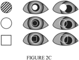
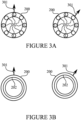
- FIGURE 3B illustrates an example illumination device in accordance with at least some embodiments of the present invention.
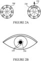
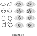
- the illuminating device comprises one or more circular-shaped light sources 202. When there are more than one such light source, they may be arranged concentrically in the illumination device. As can be seen from the rotation, visible from the direction of axis 301 on the left and on the right of FIGURE 3B , this light source is of a shape which is invariant to rotation, wherefore it need not be re-programmed responsive to a rotation of the illumination device 200.
- the illumination device may have a rotation-sensitive sensor, such as a gyroscope, such as a MEMS gyroscope, to determine that a rotation has taken place and to derive the indication thereof as a response to the rotation.
- a rotation-sensitive sensor such as a gyroscope, such as a MEMS gyroscope
- the illumination device comprises two circular-, or other geometrically shaped light sources 202, such that a smaller one of the circular- or other geometrically shaped light sources is disposed inside the larger one in a non-concentric manner, thus enabling determination of an extent of rotation of the illumination device.
- FIGURE 3C illustrates examples of non-symmetric and non-concentric illumination features schematically represented in two orientations, zero (0) and thirty (30) degrees counter-clockwise, whose properties allow for distinguishing the same orientation in their reflections on top of the eye, even while the surface of the eye may distort the figures.
- These illumination features may have a greatest dimension of at least three millimetres, for example.
- a rotation of the illumination device may be measured based on determining an extent of rotation of the glint.
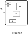
- FIGURE 4 illustrates an example device in accordance with at least some embodiments of the present invention. Illustrated is device 400, which may comprise, for example, gaze tracking apparatus.
- processor 410 which may comprise, for example, a single- or multi-core processor wherein a single-core processor comprises one processing core and a multi-core processor comprises more than one processing core.
- Processor 410 may comprise, in general, a control device.
- Processor 410 may comprise more than one processor.
- Processor 410 may be a control device.
- a processing core may comprise, for example, a Cortex-A8 processing core manufactured by ARM Holdings or a Steamroller processing core designed by Advanced Micro Devices Corporation.
- Processor 410 may comprise at least one Qualcomm Snapdragon and/or Intel Atom processor.
- Device 400 may comprise a transmitter 430.
- Device 400 may comprise a receiver 440.
- Transmitter 430 and receiver 440 may be configured to transmit and receive, respectively, information in accordance with a predetermined protocol.
- Device 400 may comprise user interface, UI, 460.
- UI 460 may comprise at least one of a display, a keyboard, a touchscreen, a vibrator arranged to signal to a user by causing device 400 to vibrate, a speaker and a microphone.
- a user may be able to operate device 400 via UI 460, for example to inspect samples on a microscope.
- Processor 410 may be furnished with a transmitter arranged to output information from processor 410, via electrical leads internal to device 400, to other devices comprised in device 400.
- a transmitter may comprise a serial bus transmitter arranged to, for example, output information via at least one electrical lead to memory 420 for storage therein.
- the transmitter may comprise a parallel bus transmitter.
- processor 410 may comprise a receiver arranged to receive information in processor 410, via electrical leads internal to device 400, from other devices comprised in device 400.
- Such a receiver may comprise a serial bus receiver arranged to, for example, receive information via at least one electrical lead from receiver 440 for processing in processor 410.
- the receiver may comprise a parallel bus receiver.
- Device 400 may comprise further devices not illustrated in FIGURE 4 . In some embodiments, device 400 lacks at least one device described above.
- Processor 410, memory 420, transmitter 430, receiver 440, and/or UI 460 may be interconnected by electrical leads internal to device 400 in a multitude of different ways.
- each of the aforementioned devices may be separately connected to a master bus internal to device 400, to allow for the devices to exchange information.
- this is only one example and depending on the embodiment various ways of interconnecting at least two of the aforementioned devices may be selected without departing from the scope of the present invention.
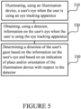
- FIGURE 5 is a flow graph of a method in accordance with at least some embodiments of the present invention.
- the phases of the illustrated method may be performed in device 400, for example, or in a control device configured to control the functioning thereof, when installed therein.
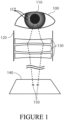
- Phase 510 comprises illuminating, using an illumination device of an eye tracker apparatus, a user's eye when the user is using an eye tracking apparatus, the illumination device comprising at least one light source.
- Phase 520 comprises obtaining, using a detector, a information on the user's eye when the user is using the eye tracking apparatus.
- phase 530 comprises determining a direction of the user's gaze based on the information on the user's eye and based on an indication of place and/or orientation of the illumination device with respect to the detector of the eye tracker apparatus.
- the information on the user's eye may comprise an image of the user's eye.
- the indication of place and/or orientation of the illumination device with respect to the detector of the eye tracker apparatus may indicate a change in the place and/or orientation of the illumination device with respect to an original orientation, for example.
- the determining of the direction of the user's gaze may comprise reading the current geometry and referencing a pre-calculated table of shapes and/or solving equations concerning shape in real time.
- At least some embodiments of the present invention find industrial application in gaze tracking applications, for example with ocular devices.
Landscapes
- Engineering & Computer Science (AREA)
- Physics & Mathematics (AREA)
- General Physics & Mathematics (AREA)
- Theoretical Computer Science (AREA)
- Multimedia (AREA)
- Health & Medical Sciences (AREA)
- Human Computer Interaction (AREA)
- General Health & Medical Sciences (AREA)
- General Engineering & Computer Science (AREA)
- Ophthalmology & Optometry (AREA)
- Life Sciences & Earth Sciences (AREA)
- Optics & Photonics (AREA)
- Computer Vision & Pattern Recognition (AREA)
- Medical Informatics (AREA)
- Vascular Medicine (AREA)
- Signal Processing (AREA)
- Biophysics (AREA)
- Biomedical Technology (AREA)
- Heart & Thoracic Surgery (AREA)
- Artificial Intelligence (AREA)
- Molecular Biology (AREA)
- Surgery (AREA)
- Animal Behavior & Ethology (AREA)
- Public Health (AREA)
- Veterinary Medicine (AREA)
- Eye Examination Apparatus (AREA)
Claims (8)
- Eye-Tracking-Einrichtung (400), umfassend:- eine Beleuchtungsvorrichtung (200, 220), die so konfiguriert ist, dass sie das Auge eines Benutzers beleuchtet, wenn der Benutzer die Eye-Tracking-Einrichtung (400) verwendet;- mindestens einen Sensor, der so konfiguriert ist, dass er Informationen über das Auge des Benutzers erhält, indem er das Auge des Benutzers abbildet, wenn der Benutzer die Eye-Tracking-Einrichtung (400) verwendet, und- mindestens einen Verarbeitungskern (410), der so konfiguriert ist, dass er eine Blickrichtung des Benutzers auf der Grundlage der Informationen über das Auge des Benutzers und auf der Grundlage einer Angabe über den Ort und die Ausrichtung der Beleuchtungsvorrichtung (200, 220) in Bezug auf den mindestens einen Sensor bestimmt, wobei der mindestens eine Verarbeitungskern (410) so konfiguriert ist, dass er die Angabe auf der Grundlage der Informationen über das Auge des Benutzers bestimmt, wobei entweder A oder B der folgenden Punkte zutrifft: A) die Beleuchtungsvorrichtung (200, 220) umfasst mindestens drei Lichtquellen (202, 222), die in der Beleuchtungsvorrichtung (200, 220) so angeordnet sind, dass Abstände zwischen aufeinanderfolgenden der mindestens drei Lichtquellen (202, 222) nicht gleich sind, was eine Bestimmung der Ausrichtung der Beleuchtungsvorrichtung (200, 220) auf der Grundlage von Schimmern der mindestens drei Lichtquellen (202, 222) auf einer Oberfläche des Auges des Benutzers ermöglicht, und B) die Beleuchtungsvorrichtung (200, 220) mindestens zwei Lichtquellen (202, 222) umfasst, wobei die Lichtquellen (202, 222) Lichtquellen (202, 222) unterschiedlicher Größe und/oder Form umfassen, die eine Bestimmung der Ausrichtung der Beleuchtungsvorrichtung (200, 220) auf der Grundlage von Schimmern der Lichtquellen (202, 222) auf einer Oberfläche des Auges des Benutzers ermöglichen, dadurch gekennzeichnet, dass der mindestens eine Verarbeitungskern (410) weiter so konfiguriert ist, dass er die Angabe von der Beleuchtungsvorrichtung (200, 220) empfängt, wobei die Beleuchtungsvorrichtung (200, 220) mindestens einen Positionserfassungssensor, einen Beschleunigungssensor und einen Rotationserfassungssensor umfasst.
- Eyetracker-Einrichtung (400) nach Anspruch 1, wobei der Rotationserfassungssensor ein Gyroskop umfasst.
- Eyetracker-Einrichtung (400) nach Anspruch 1 oder 2, wobei der Positionserfassungssensor eine elektromagnetische Multilaterationsvorrichtung oder eine elektromagnetische Triangulationsvorrichtung umfasst.
- Eyetracker-Einrichtung (400) nach einem vorstehenden Anspruch, wobei der mindestens eine Verarbeitungskern (410) so konfiguriert ist, dass er die Angabe auf der Grundlage der Identifizierung mindestens einer der Lichtquellen (202, 222) auf der Grundlage mindestens einer physikalischen Eigenschaft der mindestens einen identifizierten Lichtquelle (202, 222) ableitet.
- Eyetracker-Einrichtung (400) nach Anspruch 4, wobei die mindestens eine physikalische Eigenschaft der mindestens einen identifizierten Lichtquelle (202, 222) mindestens eine der Folgenden umfasst: eine Größe der Lichtquelle (202, 222), eine Form der Lichtquelle (202, 222), eine Spektrumeigenschaft des von der Lichtquelle (202, 222) emittierten Lichts, eine Eigenschaft der zeitlichen Varianz des von der Lichtquelle (202, 222) abgegebenen Lichts und eine Eigenschaft der Polarisation des von der Lichtquelle (202, 222) abgegebenen Lichts.
- Verfahren, umfassend:- Beleuchten (510) des Auges eines Benutzers unter Verwendung einer Beleuchtungsvorrichtung einer Eyetracker-Einrichtung, wenn der Benutzer die Eye-Tracking-Einrichtung verwendet, wobei die Beleuchtungsvorrichtung mindestens eine Lichtquelle umfasst;- Erhalten (520) von Informationen über das Auge des Benutzers unter Verwendung mindestens eines Sensors, der das Auge des Benutzers abbildet, wenn der Benutzer die Eye-Tracking-Einrichtung verwendet, und- Bestimmen (530) einer Blickrichtung des Benutzers auf der Grundlage der Informationen über das Auge des Benutzers und auf der Grundlage einer Angabe über den Ort und die Ausrichtung der Beleuchtungsvorrichtung in Bezug auf den mindestens einen Detektor, wobei das Verfahren Bestimmen der Angabe auf der Grundlage der Informationen über das Auge des Benutzers umfasst, wobei entweder A oder B der folgenden Punkte zutrifft: A) mindestens drei Lichtquellen sind in der Beleuchtungsvorrichtung so angeordnet, dass die Abstände zwischen aufeinanderfolgenden der mindestens drei Lichtquellen nicht gleich sind, was eine Bestimmung der Ausrichtung der Beleuchtungsvorrichtung auf der Grundlage von Schimmern der mindestens drei Lichtquellen auf einer Oberfläche des Auges des Benutzers ermöglicht, und B) die Beleuchtungsvorrichtung umfasst mindestens zwei Lichtquellen, wobei die Lichtquellen Lichtquellen unterschiedlicher Größe und/oder Form umfassen, was eine Bestimmung der Ausrichtung der Beleuchtungsvorrichtung auf der Grundlage von Schimmern der Lichtquellen auf einer Oberfläche des Auges des Benutzers ermöglicht, dadurch gekennzeichnet, dass das Verfahren weiter umfasstEmpfangen der Angabe von der Beleuchtungsvorrichtung, wobei die Beleuchtungsvorrichtung mindestens einen Positionserfassungssensor, einen Beschleunigungssensor und einen Rotationserfassungssensor umfasst.
- Verfahren nach Anspruch 6, wobei der Rotationserfassungssensor ein Gyroskop umfasst.
- Computerprogramm, das so konfiguriert ist, dass es die Durchführung eines Verfahrens nach mindestens einem der Ansprüche 6-7 veranlasst, wenn es auf einer Eye-Tracking-Einrichtung ausgeführt wird, die eine Beleuchtungsvorrichtung, mindestens einen Detektor und mindestens einen Verarbeitungskern umfasst.
Applications Claiming Priority (2)
| Application Number | Priority Date | Filing Date | Title |
|---|---|---|---|
| FI20215098A FI131423B1 (en) | 2021-01-29 | 2021-01-29 | Eye tracking lighting |
| PCT/FI2022/050053 WO2022162276A1 (en) | 2021-01-29 | 2022-01-27 | Eye tracking illumination |
Publications (4)
| Publication Number | Publication Date |
|---|---|
| EP4285204A1 EP4285204A1 (de) | 2023-12-06 |
| EP4285204B1 true EP4285204B1 (de) | 2025-07-02 |
| EP4285204C0 EP4285204C0 (de) | 2025-07-02 |
| EP4285204B8 EP4285204B8 (de) | 2025-08-20 |
Family
ID=80218559
Family Applications (1)
| Application Number | Title | Priority Date | Filing Date |
|---|---|---|---|
| EP22702496.5A Active EP4285204B8 (de) | 2021-01-29 | 2022-01-27 | Augenverfolgungsbeleuchtung |
Country Status (4)
| Country | Link |
|---|---|
| US (1) | US20240428544A1 (de) |
| EP (1) | EP4285204B8 (de) |
| FI (1) | FI131423B1 (de) |
| WO (1) | WO2022162276A1 (de) |
Families Citing this family (3)
| Publication number | Priority date | Publication date | Assignee | Title |
|---|---|---|---|---|
| EP4394558A1 (de) * | 2022-12-26 | 2024-07-03 | Canon Kabushiki Kaisha | Sichtlinienerkennungsvorrichtung und kopfmontierte anzeigevorrichtung |
| JP2024092340A (ja) * | 2022-12-26 | 2024-07-08 | キヤノン株式会社 | 視線検出装置 |
| EP4394557A1 (de) * | 2022-12-26 | 2024-07-03 | Canon Kabushiki Kaisha | Sichtlinienerkennungsvorrichtung und kopfmontierte anzeigevorrichtung |
Family Cites Families (14)
| Publication number | Priority date | Publication date | Assignee | Title |
|---|---|---|---|---|
| WO2007085682A1 (en) * | 2006-01-26 | 2007-08-02 | Nokia Corporation | Eye tracker device |
| KR101001338B1 (ko) * | 2009-08-24 | 2010-12-14 | 씨엠아이텍주식회사 | 신원 확인 장치 |
| KR101248529B1 (ko) * | 2011-07-25 | 2013-04-03 | 한국과학기술연구원 | 선광원을 사용한 입체영상 표시장치 |
| US8913789B1 (en) * | 2012-01-06 | 2014-12-16 | Google Inc. | Input methods and systems for eye positioning using plural glints |
| JP6340838B2 (ja) * | 2014-03-10 | 2018-06-13 | 富士通株式会社 | 生体認証装置、生体認証方法及びプログラム |
| CN106922182B (zh) * | 2014-11-14 | 2020-01-24 | 依视路国际公司 | 确定眼睛的显著点的位置和跟踪眼镜配戴者的注视方向的设备和方法 |
| US10419655B2 (en) * | 2015-04-27 | 2019-09-17 | Snap-Aid Patents Ltd. | Estimating and using relative head pose and camera field-of-view |
| US10698482B2 (en) * | 2016-12-01 | 2020-06-30 | Varjo Technologies Oy | Gaze tracking using non-circular lights |
| US10482340B2 (en) * | 2016-12-06 | 2019-11-19 | Samsung Electronics Co., Ltd. | System and method for object recognition and ranging by deformation of projected shapes in a multimodal vision and sensing system for autonomous devices |
| US10698481B1 (en) * | 2017-09-28 | 2020-06-30 | Apple Inc. | Glint-assisted gaze tracker |
| FI20175960A1 (en) * | 2017-10-30 | 2019-05-01 | Univ Of Eastern Finland | Procedure and apparatus for gaze detection |
| US10222474B1 (en) * | 2017-12-13 | 2019-03-05 | Soraa Laser Diode, Inc. | Lidar systems including a gallium and nitrogen containing laser light source |
| JP7227989B2 (ja) * | 2018-08-21 | 2023-02-22 | メタ プラットフォームズ テクノロジーズ, リミテッド ライアビリティ カンパニー | 視野内マイクロデバイスを備えた照明アセンブリ |
| WO2021050329A1 (en) * | 2019-09-09 | 2021-03-18 | Apple Inc. | Glint-based gaze tracking using directional light sources |
-
2021
- 2021-01-29 FI FI20215098A patent/FI131423B1/en active
-
2022
- 2022-01-27 EP EP22702496.5A patent/EP4285204B8/de active Active
- 2022-01-27 WO PCT/FI2022/050053 patent/WO2022162276A1/en not_active Ceased
- 2022-01-27 US US18/263,349 patent/US20240428544A1/en active Pending
Also Published As
| Publication number | Publication date |
|---|---|
| FI20215098A1 (en) | 2022-07-30 |
| US20240428544A1 (en) | 2024-12-26 |
| WO2022162276A1 (en) | 2022-08-04 |
| EP4285204C0 (de) | 2025-07-02 |
| FI131423B1 (en) | 2025-04-15 |
| EP4285204B8 (de) | 2025-08-20 |
| EP4285204A1 (de) | 2023-12-06 |
Similar Documents
| Publication | Publication Date | Title |
|---|---|---|
| CA3087333C (en) | EYE ROTATION CENTER DETERMINATION, DEPTH PLANE SELECTION AND RENDERING CAMERA POSITIONING IN DISPLAY SYSTEMS | |
| EP4285204B1 (de) | Augenverfolgungsbeleuchtung | |
| CN104834381B (zh) | 用于视线焦点定位的可穿戴设备及视线焦点定位方法 | |
| CN105431076B (zh) | 视线引导装置 | |
| EP3294113B1 (de) | Augenverfolgungsvorrichtung und verfahren zum betrieb einer augenverfolgungsvorrichtung | |
| US6394602B1 (en) | Eye tracking system | |
| JP6308940B2 (ja) | 視線追跡シーン参照位置を識別するシステム及び方法 | |
| US20190042842A1 (en) | Eye tracking using time multiplexing | |
| EP3746838B1 (de) | Blickverfolgungssystem und blendenvorrichtung | |
| US11435820B1 (en) | Gaze detection pipeline in an artificial reality system | |
| CN110398830A (zh) | 显微系统以及用于操作显微系统的方法 | |
| EP2812775A1 (de) | Blickverfolgung mit einem projektor | |
| US12432333B2 (en) | Dynamic illumination for eye-tracking | |
| EP4320499B1 (de) | Blickverfolgungssystem und -verfahren mit selektiven schimmern | |
| CN119492521A (zh) | 可切换的测试设备、方法、电子设备、存储介质及程序产品 | |
| US10534156B2 (en) | Devices and methods for lens alignment based on encoded color patterns | |
| US12086309B2 (en) | Gaze tracking | |
| US12505573B2 (en) | Gaze tracking |
Legal Events
| Date | Code | Title | Description |
|---|---|---|---|
| STAA | Information on the status of an ep patent application or granted ep patent |
Free format text: STATUS: UNKNOWN |
|
| STAA | Information on the status of an ep patent application or granted ep patent |
Free format text: STATUS: THE INTERNATIONAL PUBLICATION HAS BEEN MADE |
|
| PUAI | Public reference made under article 153(3) epc to a published international application that has entered the european phase |
Free format text: ORIGINAL CODE: 0009012 |
|
| STAA | Information on the status of an ep patent application or granted ep patent |
Free format text: STATUS: REQUEST FOR EXAMINATION WAS MADE |
|
| 17P | Request for examination filed |
Effective date: 20230810 |
|
| AK | Designated contracting states |
Kind code of ref document: A1 Designated state(s): AL AT BE BG CH CY CZ DE DK EE ES FI FR GB GR HR HU IE IS IT LI LT LU LV MC MK MT NL NO PL PT RO RS SE SI SK SM TR |
|
| DAV | Request for validation of the european patent (deleted) | ||
| DAX | Request for extension of the european patent (deleted) | ||
| GRAP | Despatch of communication of intention to grant a patent |
Free format text: ORIGINAL CODE: EPIDOSNIGR1 |
|
| STAA | Information on the status of an ep patent application or granted ep patent |
Free format text: STATUS: GRANT OF PATENT IS INTENDED |
|
| RIC1 | Information provided on ipc code assigned before grant |
Ipc: G02B 27/01 20060101ALI20250318BHEP Ipc: G02B 27/00 20060101ALI20250318BHEP Ipc: G06F 3/01 20060101AFI20250318BHEP |
|
| INTG | Intention to grant announced |
Effective date: 20250327 |
|
| GRAS | Grant fee paid |
Free format text: ORIGINAL CODE: EPIDOSNIGR3 |
|
| GRAA | (expected) grant |
Free format text: ORIGINAL CODE: 0009210 |
|
| STAA | Information on the status of an ep patent application or granted ep patent |
Free format text: STATUS: THE PATENT HAS BEEN GRANTED |
|
| AK | Designated contracting states |
Kind code of ref document: B1 Designated state(s): AL AT BE BG CH CY CZ DE DK EE ES FI FR GB GR HR HU IE IS IT LI LT LU LV MC MK MT NL NO PL PT RO RS SE SI SK SM TR |
|
| RAP3 | Party data changed (applicant data changed or rights of an application transferred) |
Owner name: SEETRUE TECHNOLOGIES OY |
|
| REG | Reference to a national code |
Ref country code: GB Ref legal event code: FG4D |
|
| REG | Reference to a national code |
Ref country code: CH Ref legal event code: EP |
|
| GRAT | Correction requested after decision to grant or after decision to maintain patent in amended form |
Free format text: ORIGINAL CODE: EPIDOSNCDEC |
|
| REG | Reference to a national code |
Ref country code: DE Ref legal event code: R096 Ref document number: 602022016851 Country of ref document: DE |
|
| REG | Reference to a national code |
Ref country code: IE Ref legal event code: FG4D |
|
| REG | Reference to a national code |
Ref country code: CH Ref legal event code: PK Free format text: BERICHTIGUNG B8 |
|
| RAP4 | Party data changed (patent owner data changed or rights of a patent transferred) |
Owner name: SEETRUE TECHNOLOGIES OY |
|
| U01 | Request for unitary effect filed |
Effective date: 20250711 |
|
| U07 | Unitary effect registered |
Designated state(s): AT BE BG DE DK EE FI FR IT LT LU LV MT NL PT RO SE SI Effective date: 20250718 |
|
| PG25 | Lapsed in a contracting state [announced via postgrant information from national office to epo] |
Ref country code: IS Free format text: LAPSE BECAUSE OF FAILURE TO SUBMIT A TRANSLATION OF THE DESCRIPTION OR TO PAY THE FEE WITHIN THE PRESCRIBED TIME-LIMIT Effective date: 20251102 |
|
| PG25 | Lapsed in a contracting state [announced via postgrant information from national office to epo] |
Ref country code: NO Free format text: LAPSE BECAUSE OF FAILURE TO SUBMIT A TRANSLATION OF THE DESCRIPTION OR TO PAY THE FEE WITHIN THE PRESCRIBED TIME-LIMIT Effective date: 20251002 |
|
| PG25 | Lapsed in a contracting state [announced via postgrant information from national office to epo] |
Ref country code: HR Free format text: LAPSE BECAUSE OF FAILURE TO SUBMIT A TRANSLATION OF THE DESCRIPTION OR TO PAY THE FEE WITHIN THE PRESCRIBED TIME-LIMIT Effective date: 20250702 |
|
| PG25 | Lapsed in a contracting state [announced via postgrant information from national office to epo] |
Ref country code: GR Free format text: LAPSE BECAUSE OF FAILURE TO SUBMIT A TRANSLATION OF THE DESCRIPTION OR TO PAY THE FEE WITHIN THE PRESCRIBED TIME-LIMIT Effective date: 20251003 |
|
| PG25 | Lapsed in a contracting state [announced via postgrant information from national office to epo] |
Ref country code: CZ Free format text: LAPSE BECAUSE OF FAILURE TO SUBMIT A TRANSLATION OF THE DESCRIPTION OR TO PAY THE FEE WITHIN THE PRESCRIBED TIME-LIMIT Effective date: 20250702 |
|
| PG25 | Lapsed in a contracting state [announced via postgrant information from national office to epo] |
Ref country code: PL Free format text: LAPSE BECAUSE OF FAILURE TO SUBMIT A TRANSLATION OF THE DESCRIPTION OR TO PAY THE FEE WITHIN THE PRESCRIBED TIME-LIMIT Effective date: 20250702 |
|
| PG25 | Lapsed in a contracting state [announced via postgrant information from national office to epo] |
Ref country code: RS Free format text: LAPSE BECAUSE OF FAILURE TO SUBMIT A TRANSLATION OF THE DESCRIPTION OR TO PAY THE FEE WITHIN THE PRESCRIBED TIME-LIMIT Effective date: 20251002 |
|
| PG25 | Lapsed in a contracting state [announced via postgrant information from national office to epo] |
Ref country code: ES Free format text: LAPSE BECAUSE OF FAILURE TO SUBMIT A TRANSLATION OF THE DESCRIPTION OR TO PAY THE FEE WITHIN THE PRESCRIBED TIME-LIMIT Effective date: 20250702 |
|
| REG | Reference to a national code |
Ref country code: CH Ref legal event code: U11 Free format text: ST27 STATUS EVENT CODE: U-0-0-U10-U11 (AS PROVIDED BY THE NATIONAL OFFICE) Effective date: 20260201 |
|
| U20 | Renewal fee for the european patent with unitary effect paid |
Year of fee payment: 5 Effective date: 20260107 |