EP4284566B1 - Verfahren zur elektronischen verfolgung der physikalischen ablagerung eines beschichtungsmaterials - Google Patents
Verfahren zur elektronischen verfolgung der physikalischen ablagerung eines beschichtungsmaterials Download PDFInfo
- Publication number
- EP4284566B1 EP4284566B1 EP22702536.8A EP22702536A EP4284566B1 EP 4284566 B1 EP4284566 B1 EP 4284566B1 EP 22702536 A EP22702536 A EP 22702536A EP 4284566 B1 EP4284566 B1 EP 4284566B1
- Authority
- EP
- European Patent Office
- Prior art keywords
- data
- spray
- coating
- spray gun
- distance
- Prior art date
- Legal status (The legal status is an assumption and is not a legal conclusion. Google has not performed a legal analysis and makes no representation as to the accuracy of the status listed.)
- Active
Links
Images
Classifications
-
- G—PHYSICS
- G01—MEASURING; TESTING
- G01B—MEASURING LENGTH, THICKNESS OR SIMILAR LINEAR DIMENSIONS; MEASURING ANGLES; MEASURING AREAS; MEASURING IRREGULARITIES OF SURFACES OR CONTOURS
- G01B21/00—Measuring arrangements or details thereof, where the measuring technique is not covered by the other groups of this subclass, unspecified or not relevant
- G01B21/02—Measuring arrangements or details thereof, where the measuring technique is not covered by the other groups of this subclass, unspecified or not relevant for measuring length, width, or thickness
- G01B21/08—Measuring arrangements or details thereof, where the measuring technique is not covered by the other groups of this subclass, unspecified or not relevant for measuring length, width, or thickness for measuring thickness
-
- B—PERFORMING OPERATIONS; TRANSPORTING
- B05—SPRAYING OR ATOMISING IN GENERAL; APPLYING FLUENT MATERIALS TO SURFACES, IN GENERAL
- B05B—SPRAYING APPARATUS; ATOMISING APPARATUS; NOZZLES
- B05B12/00—Arrangements for controlling delivery; Arrangements for controlling the spray area
- B05B12/004—Arrangements for controlling delivery; Arrangements for controlling the spray area comprising sensors for monitoring the delivery, e.g. by displaying the sensed value or generating an alarm
- B05B12/006—Pressure or flow rate sensors
- B05B12/008—Pressure or flow rate sensors integrated in or attached to a discharge apparatus, e.g. a spray gun
-
- B—PERFORMING OPERATIONS; TRANSPORTING
- B05—SPRAYING OR ATOMISING IN GENERAL; APPLYING FLUENT MATERIALS TO SURFACES, IN GENERAL
- B05B—SPRAYING APPARATUS; ATOMISING APPARATUS; NOZZLES
- B05B12/00—Arrangements for controlling delivery; Arrangements for controlling the spray area
- B05B12/02—Arrangements for controlling delivery; Arrangements for controlling the spray area for controlling time, or sequence, of delivery
-
- B—PERFORMING OPERATIONS; TRANSPORTING
- B05—SPRAYING OR ATOMISING IN GENERAL; APPLYING FLUENT MATERIALS TO SURFACES, IN GENERAL
- B05B—SPRAYING APPARATUS; ATOMISING APPARATUS; NOZZLES
- B05B12/00—Arrangements for controlling delivery; Arrangements for controlling the spray area
- B05B12/08—Arrangements for controlling delivery; Arrangements for controlling the spray area responsive to condition of liquid or other fluent material to be discharged, of ambient medium or of target ; responsive to condition of spray devices or of supply means, e.g. pipes, pumps or their drive means
- B05B12/082—Arrangements for controlling delivery; Arrangements for controlling the spray area responsive to condition of liquid or other fluent material to be discharged, of ambient medium or of target ; responsive to condition of spray devices or of supply means, e.g. pipes, pumps or their drive means responsive to a condition of the discharged jet or spray, e.g. to jet shape, spray pattern or droplet size
-
- B—PERFORMING OPERATIONS; TRANSPORTING
- B05—SPRAYING OR ATOMISING IN GENERAL; APPLYING FLUENT MATERIALS TO SURFACES, IN GENERAL
- B05B—SPRAYING APPARATUS; ATOMISING APPARATUS; NOZZLES
- B05B12/00—Arrangements for controlling delivery; Arrangements for controlling the spray area
- B05B12/08—Arrangements for controlling delivery; Arrangements for controlling the spray area responsive to condition of liquid or other fluent material to be discharged, of ambient medium or of target ; responsive to condition of spray devices or of supply means, e.g. pipes, pumps or their drive means
- B05B12/12—Arrangements for controlling delivery; Arrangements for controlling the spray area responsive to condition of liquid or other fluent material to be discharged, of ambient medium or of target ; responsive to condition of spray devices or of supply means, e.g. pipes, pumps or their drive means responsive to conditions of ambient medium or target, e.g. humidity, temperature position or movement of the target relative to the spray apparatus
- B05B12/124—Arrangements for controlling delivery; Arrangements for controlling the spray area responsive to condition of liquid or other fluent material to be discharged, of ambient medium or of target ; responsive to condition of spray devices or of supply means, e.g. pipes, pumps or their drive means responsive to conditions of ambient medium or target, e.g. humidity, temperature position or movement of the target relative to the spray apparatus responsive to distance between spray apparatus and target
-
- B—PERFORMING OPERATIONS; TRANSPORTING
- B05—SPRAYING OR ATOMISING IN GENERAL; APPLYING FLUENT MATERIALS TO SURFACES, IN GENERAL
- B05B—SPRAYING APPARATUS; ATOMISING APPARATUS; NOZZLES
- B05B12/00—Arrangements for controlling delivery; Arrangements for controlling the spray area
- B05B12/08—Arrangements for controlling delivery; Arrangements for controlling the spray area responsive to condition of liquid or other fluent material to be discharged, of ambient medium or of target ; responsive to condition of spray devices or of supply means, e.g. pipes, pumps or their drive means
- B05B12/12—Arrangements for controlling delivery; Arrangements for controlling the spray area responsive to condition of liquid or other fluent material to be discharged, of ambient medium or of target ; responsive to condition of spray devices or of supply means, e.g. pipes, pumps or their drive means responsive to conditions of ambient medium or target, e.g. humidity, temperature position or movement of the target relative to the spray apparatus
- B05B12/126—Arrangements for controlling delivery; Arrangements for controlling the spray area responsive to condition of liquid or other fluent material to be discharged, of ambient medium or of target ; responsive to condition of spray devices or of supply means, e.g. pipes, pumps or their drive means responsive to conditions of ambient medium or target, e.g. humidity, temperature position or movement of the target relative to the spray apparatus responsive to target velocity, e.g. to relative velocity between spray apparatus and target
-
- B—PERFORMING OPERATIONS; TRANSPORTING
- B05—SPRAYING OR ATOMISING IN GENERAL; APPLYING FLUENT MATERIALS TO SURFACES, IN GENERAL
- B05B—SPRAYING APPARATUS; ATOMISING APPARATUS; NOZZLES
- B05B12/00—Arrangements for controlling delivery; Arrangements for controlling the spray area
- B05B12/16—Arrangements for controlling delivery; Arrangements for controlling the spray area for controlling the spray area
-
- B—PERFORMING OPERATIONS; TRANSPORTING
- B05—SPRAYING OR ATOMISING IN GENERAL; APPLYING FLUENT MATERIALS TO SURFACES, IN GENERAL
- B05D—PROCESSES FOR APPLYING FLUENT MATERIALS TO SURFACES, IN GENERAL
- B05D1/00—Processes for applying liquids or other fluent materials
- B05D1/02—Processes for applying liquids or other fluent materials performed by spraying
-
- C—CHEMISTRY; METALLURGY
- C23—COATING METALLIC MATERIAL; COATING MATERIAL WITH METALLIC MATERIAL; CHEMICAL SURFACE TREATMENT; DIFFUSION TREATMENT OF METALLIC MATERIAL; COATING BY VACUUM EVAPORATION, BY SPUTTERING, BY ION IMPLANTATION OR BY CHEMICAL VAPOUR DEPOSITION, IN GENERAL; INHIBITING CORROSION OF METALLIC MATERIAL OR INCRUSTATION IN GENERAL
- C23C—COATING METALLIC MATERIAL; COATING MATERIAL WITH METALLIC MATERIAL; SURFACE TREATMENT OF METALLIC MATERIAL BY DIFFUSION INTO THE SURFACE, BY CHEMICAL CONVERSION OR SUBSTITUTION; COATING BY VACUUM EVAPORATION, BY SPUTTERING, BY ION IMPLANTATION OR BY CHEMICAL VAPOUR DEPOSITION, IN GENERAL
- C23C18/00—Chemical coating by decomposition of either liquid compounds or solutions of the coating forming compounds, without leaving reaction products of surface material in the coating; Contact plating
- C23C18/02—Chemical coating by decomposition of either liquid compounds or solutions of the coating forming compounds, without leaving reaction products of surface material in the coating; Contact plating by thermal decomposition
- C23C18/06—Coating on selected surface areas, e.g. using masks
Definitions
- the invention relates to a sensor kit for a spray gun and processing of data received from the sensor kit.
- US 2005/242205 A1 shows a spray coating apparatus comprising a spray gun operable to deposit a sprayed coating via a spray nozzle onto a surface, a mapping means associated with the spray gun operable to ascertain and store topographical characteristics of the surface, a position sensor operable to ascertain the position of the spray gun relative to the surface, and a coating thickness monitor operable to ascertain the thickness of a coating applied to the surface, the apparatus further including a display means operable to display to an operator the deposition of the sprayed coating on the surface.
- Spray guns for spraying coating fluids are precision instruments, of which characteristics are well known.
- One particular characteristic is the shape of the spray cone, the flow rate of coating fluid and the density of fluid in the spray cone.
- a model of the spray cone a three-dimensional coating model may be construed.
- Such model may comprise, at various locations in the cone, for example at regular grid points, each grid point representing a particular volume, a mass flow or volume flow within the particular volume.
- the location of the physical surface on which the coating fluid impinges is known relative to the nozzle of the spray gun may be determined. And with that information, the mass flow or volume flow of coating fluid within the spray cone at the physical surface may be determined as positional spray paint deposition, in this case per unit of time.
- An implementation of the first aspect further comprises calculating, based on the distance data, the position data, the coating deposition area data and time, characteristics of a layer of coating fluid on the physical surface. With a deposition rate of coating fluid known in a plane where the physical surface and the spray cone intersect, building up of a layer by virtue of that deposition may be calculated, including characteristics of that layer.
- the positional sensing system comprises a first accelerometer for determining a first acceleration substantially perpendicular to the spray direction and a second accelerometer for determining a second acceleration substantially perpendicular to the spray direction, the first direction being substantially perpendicular to the second direction.
- the method further comprises integrating the first acceleration in time twice over time for obtaining first displacement data in the first direction as a first part of the position data and integrating the second acceleration in time twice over time for obtaining second displacement data in the second direction as a second part of the position data.
- velocity data may be determined.
- velocity and displacement of the sensor kit may be calculated.
- velocity and displacement of the nozzle may be calculated.
- displacement of the spray cone may be determined.
- displacement of the spray cone and the plane of intersection of the spray cone and the surface may be determined. This data may be used to determine deposition of coating fluid on the surface over time, over an area over which the cone is displaced. Additionally, other data, like distance data may be used.
- Yet another implementation further comprises determining, based the received position data, whether the spray gun is moving in a swinging motion and starting the calculating if it is determined that the spray gun is moving in a swinging motion.
- Spraying of coating fluids is mostly done by swinging the spray gun.
- An amount of actuators on the spray kit is preferably kept as low as possible, if possible such actuable inputs are eliminated. By automatic detection of a start of the spraying process, no actuator may be required to start the logging of data.
- the positional sensing system comprising at least one of a first accelerometer and a second accelerometer and determining whether the spray gun is moving in a swinging motion comprises determining whether the acceleration value of at least one of a first accelerometer and a second accelerometer changes sign at least two times during a pre-determined interval. Swinging may be performed sideways, up and down or a combination thereof. At the extremities of a swing and in the middle of a swing, the value of the acceleration will change sign.
- determining whether the spray gun is moving in a swinging motion comprises determining whether the acceleration value of at least one of a first accelerometer and a second accelerometer changes sign at least three times during a pre-determined interval and a first time period between a first sign change and a second sign change varies from a second time period between the second sign change and a third sign change by less than a pre-determined amount.
- the acceleration will change sign three times.
- the time periods between the zero crossing will be substantially the same - give or take 2% to 5% or possibly 5% to 10%.
- Another implementation further comprises determining an orientation of the spray gun and the spray direction relative to the physical surface and calculating the coating deposition area data of positional spray coating deposition is also based on the orientation.
- the coating fluid may not be deposited in the intended circular or elliptical area, but in an area having a different shape. Using data on the orientation of the spray cone relative to the physical surface and using angle data in particular aids in this issue.
- the distance sensor module comprises multiple distance sensors and determining the orientation comprises obtaining multiple distance sensor values from the comprises multiple distance sensors and determining the orientation based on differences between the multiple distance sensor values. With distance sensors provided in a plane perpendicular to the spray direction, distances detected are substantially equal. If the sensor kit and with that, the spray direction is not provided to the physical surface in a perpendicular direction, the distances measures are different and with that, also sensor values. From the sensor values, the angle may be determined.
- Another implementation further comprises receiving, from the positional sensing system, rotational data indicative of a rotational position of the spray gun transversal to the spray direction and determining, based on the position data and the rotational data, the orientation. This provides another way of determining the orientation.
- calculating the coating deposition area data of positional spray coating deposition comprises determining cone intersection plane coating fluid data, based on the distance data and the three-dimensional coating model data and calculating the coating deposition area data of positional spray coating deposition is based on the cone intersection plane coating fluid data.
- the cone intersection plane coating fluid data may comprise data on a deposition rate in a particular area, for example volume or mass.
- the intersection of cone and physical surface defines an area and deposition may be determined in that area. And if displacement data over time is used, a layer and thickness thereof on the physical surface may be determined.
- Again another implementation further comprises receiving an input related to selection of a pre-determined coating fluid; and obtaining the three-dimensional coating model data of the spray cone associated with the spray gun in response to providing data related to the pre-determined coating fluid to the electronic memory.
- Different types of coating have different characteristics. With this implementation, different characteristics may be taken into account, providing more accurate data. Additionally or alternatively, other data like humidity, temperature, other environmental data on an ambient environment, other data, or a combination thereof may be taken into account.
- a further implementation further comprises obtaining coating fluid flow data providing an indication of a mass flow rate of the coating fluid through the spray gun and adjusting the coating model data based on the coating fluid flow data.
- Different types of coating may have different spray characteristics, like droplet size, droplet density, viscosity, relative mass, flow rate dependency on air pressure and/or air flow, other, or a combination thereof. This implementation takes that into account, providing more accurate data.
- Coating fluid data may be indicated by a directly or indirectly measured mass flow or volume flow of coating fluid. A flow of actual coating fluid may be measured and determined. Alternatively of additionally, flow of air, optionally with features including at least one of pressure, mass flow, flow velocity, supply duct bore diameter, other, or a combination thereof and the flow of coating fluid may be determined based on the flow of air and, optionally, other parameters.
- the coating fluid flow data is provided with a first timestamp the distance data is provided with a second timestamp and the position data is provided with a third timestamp, the method further comprising matching the fluid flow data, the distance data and the position data over time based on the first timestamp, the second timestamp and the third timestamp. Determining flow data may not be possible with the sensor kit, as it may require direct contact with a flow of coating fluid and/or air and the sensor kit is preferably conveniently detachable from the spray gun. Hence, if data from multiple entities is to be used over time, the data may be synchronised using time stamps.
- Yet a further implementation further comprises obtaining data for providing the first timestamp, the second timestamp and the third timestamp from a network source and providing the coating fluid flow data with the first timestamp, the distance data with the second timestamp and the position data with the third timestamp.
- Network routers wired and wireless, may be arranged to provide timing data. With such timing data being synchronised, it may serve providing timestamps suitable for synchronisation.
- Another implementation further comprises calculating, based on the coating deposition area data of positional spray coating deposition on the area of the physical surface per unit of time, thickness of a layer of coating fluid on the physical surface. With a total mass flow available, distribution of the flow over the cone and the location of the physical surface relative to the cone over time, the total deposition of coating fluid per unit area may be determined over time. At the moment the spray job has ended, thickness of a layer may be determined.
- Another implementation further comprises obtaining curing data related to the coating fluid and based on the curing data, determining cured thickness of a cured layer of coating fluid on the physical surface.
- the thickness of the cured layer is relevant, in particular at certain locations on the physical surface.
- the thickness of the cured layer is generally less than the thickness of a layer that has just been sprayed.
- the relation between a just sprayed layer, that may be wet, and a cured layer, that may be dry, may be linear or non-linear.
- a second aspect provides an electronic computing device configured for electronically tracking of spray coating of a coating fluid on a physical surface by a spray gun arranged to spray the coating fluid in a spray direction.
- the device comprises a communication unit arranged to receive, from a distance sensor module comprising at least one distance sensor, the distance sensor module being connected to the spray gun, distance data indicating a physical distance between the spray gun and the surface, obtain, from an electronic memory, three-dimensional coating model data of a spray cone associated with the spray gun, receive, from a positional sensing system connected to the spray gun, position data providing an indication of the spray gun relative to a first position on the physical surface.
- the device further comprises a processing unit arranged to calculate, based on the distance data, the position data and the three-dimensional coating model, coating deposition area data of positional spray coating deposition on an area of the physical surface per unit of time.
- a third aspect provides a computer programme product comprising computer executable instructions causing a computer, when the instructions are executed by a processor comprised by the computer, to execute a method of electronically tracking of spray coating of a coating fluid on a physical surface by a spray gun arranged to spray the coating fluid in a spray direction.
- the method comprises receiving, from a distance sensor module comprising at least one distance sensor, the distance sensor module being connected to the spray gun, distance data indicating a physical distance between the spray gun and the surface, obtaining, from an electronic memory, three-dimensional coating model data of a spray cone associated with the spray gun, receiving, from a positional sensing system connected to the spray gun, position data providing an indication of the spray gun relative to a first position on the physical surface and calculating, based on the distance data, the position data and the three-dimensional coating model, coating deposition area data of positional spray coating deposition on an area of the physical surface per unit of time.
- a fourth aspect provides a non-transitional medium having stored thereon a computer programme product comprising computer executable instructions causing a computer, when the instructions are executed by a processor comprised by the computer, to execute a method of electronically tracking of spray coating of a coating fluid on a physical surface by a spray gun arranged to spray the coating fluid in a spray direction.
- the method comprises receiving, from a distance sensor module comprising at least one distance sensor, the distance sensor module being connected to the spray gun, distance data indicating a physical distance between the spray gun and the surface, obtaining, from an electronic memory, three-dimensional coating model data of a spray cone associated with the spray gun, receiving, from a positional sensing system connected to the spray gun, position data providing an indication of the spray gun relative to a first position on the physical surface and calculating, based on the distance data, the position data and the three-dimensional coating model, coating deposition area data of positional spray coating deposition on an area of the physical surface per unit of time.
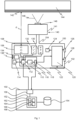
- Fig. 1 depicts a schematic overview of an embodiment of a sensor kit 100 comprising a sensor kit body 102 as a housing.
- the sensor kit body 102 comprises a spray gun connector 104 as a connection module.
- a spray gun 140 is connected to the body 102 via the connector 104.
- the spray gun 140 comprises a spray gun housing 141.
- the spray gun 140 may for example be a High Volume Low Pressure (HVLP) spray gun.
- HVLP High Volume Low Pressure
- the emitted optical signal may have a near infrared wavelength spectrum, for example between 800 and 1140 nm, more in particular between 900 nm and 1000 nm and most preferably 940nm. Electromagnetic radiation of such wave is not visible; it may travel through substance that may seem opaque to the human eye, but is transparent for electromagnetic radiation between 900 nm and 1000 nm and 940 nm in particular.
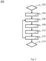
- the method 200 is initialised by the user connecting the sensor kit 100 to the spray gun 140.
- the spray gun 140 be provided with a magnet, arranged to manipulate a magnetic switch like a reed contact comprised by the sensor kit 100 for switching on the sensor kit 100.
- the user selects the type of coating to be sprayed by the spray gun 140, for example by selecting this type via a graphical user interface arranged to allow user interaction with the server 150.
- the server 150 may be embodied as an application on a smartphone, tablet, personal computer device, or any other device which allows to user to select a type of coating.
- a barcode scanner may be provided for scanning a barcode on a container of coating substance for obtaining data indicative of the type of coating. Parts of the scanner may be incorporated in the sensor kit 100.
- the server 150 looks up reference parameter values corresponding to the type of coating, for example in an internal or external memory, directly or via a connection such as a LAN, WAN, internet, Wi-Fi, Bluetooth, or any other wired or wireless connection.
- a connection such as a LAN, WAN, internet, Wi-Fi, Bluetooth, or any other wired or wireless connection.
- a part of the reference parameter values may be provided locally, whereas another part of the reference parameter values may be provided at a remote location.
- the server 150 sends the reference parameter values to the sensor kit 100, of which the data input 112 receives the reference parameter values and stores it on the memory 114.
- the reference parameter values in this example comprise a desired distance range, particular to the selected type of coating.
- the sensor kit 100 may aid the user in keeping the spray gun 140 within this desired distance range, by providing feedback.
- the desired distance range as an example of reference parameter values may have been supplied by the manufacturer of the coating.
- the desired distance range may correspond to the distance between the nozzle 146 of the spray gun and the surface 144, or between any other component of the spray gun and the surface 144, or to the distance d between the time-of-flight sensor 106 and the surface 144.
- any of these distances may be indicative for the distance between the nozzle 146 and the surface 144.
- a dynamic model of the substantially not rigid connection may be used for mapping data obtained by the sensor kit to data relevant to the spray gun.
- the time-of-flight sensor 106 obtains distance data indicative of the distance d between the time-of-flight sensor 106 and the surface 144 facing the time-of-flight sensor 106. This distance data is then used by the comparison module 116 which compares the obtained data to the desired distance range.
- a result of this comparison may comprise a value indicating whether a particular data point in the distance data lies within the range, or falls outside the range.
- a result of this comparison may alternatively or additionally comprise a value indicating, when a particular data point falls outside the range, if the particular data point is too large, to small, and/or by what amount the data point falls outside the range.
- the output module outputs the comparison data signal to the feedback controller 120, which may be arranged to provide feedback of the comparison data signal to the user using the spray gun 140.
- the feedback is preferably provided substantially in real-time such that the user can alter his usage of the spray gun 140 adequately in accordance with the provided feedback.
- the feedback controller 140 After having received the comparison data signal, the feedback controller 140 generates a feedback signal based on at least part of the comparison data signal.
- the feedback controller 140 comprises an LED-module 126 comprised by an optical module for providing a visual signal to the user based on the generated feedback signal.
- the LED-module 126 may comprise one or more LEDs, which may be arranged to provide light of a single colour or may be controllable to provide light of different colours, for example red, green, blue, or a combination thereof.
- the feedback controller 140 may control the LED-module 126 to show a green light as an example of coloured light.
- the feedback controller 140 may control the LED-module 126 to show a red light as an example of a differently coloured light.
- the feedback controller 140 comprises a display 122 as part of the optical module, arranged for providing a visual signal based on the feedback signal.
- the display 122 may be arranged to show a value corresponding to the actual distance data obtained by the time-of-flight sensor 106, and may thus be arranged to show numerical values corresponding for example to the measured distance in millimetres or inches.
- the obtained distance data may either be supplied to the display 122 directly, or via the feedback controller 140.
- the feedback controller 140 may be arranged to generate a feedback signal to control the vibration unit 128 to provide the user with haptic feedback indicating that the desired distance has not been met for the pre-determined amount of time.
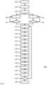
- Fig. 3 depicts a second flowchart 300 of reconstructing coating data, which may be performed in the server system 150 for communicating with a sensor kit 100 for the spray gun 140, or on a different computer device such as a smartphone or tablet computer.
- the various parts of the second flowchart 300 are briefly summarised below:
- coating data is obtained.
- Such coating data may be obtained on received data from a user of the spray gun 140.
- the input may be provided manually, by receiving data from a keyboard, by means of a barcode scanner, by receiving input through selection of an icon, other, or a combination thereof.
- the coating data comprises characteristics specifically related to at least one of the coating liquid, like viscosity, brand name, solution liquid content, data on layer thickness reduction over curing, desired distance to the surface to coat, other, or a combination thereof.
- paint model data is obtained.
- the paint model data comprises data mainly related to the spray gun 140.
- the paint model data comprises data on the structure of the spray gun 140 and the structure of a spray cone provided by the nozzle 146.
- the data may be two-dimensional, only perpendicular to the direction of spraying, or three-dimensional.
- the paint model data may comprise average flow density, median flow density, maximum flow density, minimum flow density, flow density as a function of location within the cone, cone apex, cone shape (circular or non-circular elliptical) and one or more of these parameters having a value depending on distance from the spray gun 140 or the nozzle 141 to the surface of the car body part, coating material characteristics, air pressure, air flow, air flow velocity, other, or a combination thereof.
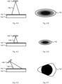
- Figure 4 E shows the nozzle 146 being placed under and angle relative to the surface of the car body part 144. With an elliptical cross-section of the spray cone 148, this may result in a cross-sectional area 142 as depicted by Figure 4 F .
- occlusions due obstructions protruding from the surface or indentations in the surface may also be taken into account when determining deposition of coating on the surface per unit area and per unit time.
- the process as discussed above may be executed continuously, while spraying continues. In particular determining final coating thickness, before or after curing, may be determined after the coating process is finished. Alternatively, some steps are executed when the spray job is finished.
Landscapes
- Chemical & Material Sciences (AREA)
- Physics & Mathematics (AREA)
- Analytical Chemistry (AREA)
- Fluid Mechanics (AREA)
- General Chemical & Material Sciences (AREA)
- Thermal Sciences (AREA)
- Chemical Kinetics & Catalysis (AREA)
- Engineering & Computer Science (AREA)
- Materials Engineering (AREA)
- Mechanical Engineering (AREA)
- Metallurgy (AREA)
- Organic Chemistry (AREA)
- General Physics & Mathematics (AREA)
- Spray Control Apparatus (AREA)
- Application Of Or Painting With Fluid Materials (AREA)
Claims (15)
- Verfahren zur elektronischen Verfolgung der Sprühbeschichtung einer Beschichtungsflüssigkeit auf einer physischen Oberfläche durch eine Sprühpistole, die so angeordnet ist, dass sie die Beschichtungsflüssigkeit in einer Sprührichtung sprüht, wobei das Verfahren in einem elektronischen Computersystem umfasst:Empfangen von Abstandsdaten, die einen physischen Abstand zwischen der Sprühpistole und der Oberfläche angeben, von einem Abstandssensormodul, das mindestens einen Abstandssensor umfasst, wobei das Abstandssensormodul mit der Sprühpistole verbunden ist;Erhalten von dreidimensionalen Beschichtungsmodelldaten aus einem elektronischen Speicher eines der Sprühpistole zugeordneten Sprühkegels;Empfangen von Positionsdaten, die eine Anzeige der Sprühpistole relativ zu einer ersten Position auf der physischen Oberfläche liefern, von einem mit der Sprühpistole verbundenen Positionserfassungssystem;Berechnen von Beschichtungsabscheidungsflächendaten der Positionssprühbeschichtungsabscheidung auf einer Fläche der physischen Oberfläche pro Zeiteinheit, basierend auf den Abstandsdaten, den Positionsdaten und dem dreidimensionalen Beschichtungsmodell.
- Verfahren nach Anspruch 1, ferner umfassend Berechnen der Eigenschaften einer Schicht aus Beschichtungsflüssigkeit auf der physischen Oberfläche, basierend auf den Abstandsdaten, den Positionsdaten, den Beschichtungsabscheidungsflächendaten und der Zeit.
- Verfahren nach einem der vorhergehenden Ansprüche, ferner umfassend:Bestimmen, basierend auf den empfangenen Positionsdaten, ob sich die Sprühpistole in einer Pendelbewegung befindet;Starten des Berechnens, wenn bestimmt wird, dass sich die Sprühpistole in einer Pendelbewegung bewegt.
- Verfahren nach einem der vorhergehenden Ansprüche, ferner umfassend:Bestimmen einer Ausrichtung der Sprühpistole und der Sprührichtung relativ zur physischen Oberfläche; undBerechnen der Beschichtungsabscheidungsflächendaten der Positionssprühbeschichtungsabscheidung ebenfalls basierend auf der Ausrichtung.
- Verfahren nach Anspruch 4, wobei das Abstandssensormodul mehrere Abstandssensoren umfasst und das Bestimmen der Ausrichtung umfasst:Erhalten mehrerer Abstandssensorwerte von den mehreren Abstandssensoren;Bestimmen der Ausrichtung basierend auf den Unterschieden zwischen den mehreren Abstandssensorwerten.
- Verfahren nach einem der vorhergehenden Ansprüche, wobeiBerechnen der Beschichtungsabscheidungsflächendaten der Positionssprühbeschichtungsabscheidung das Bestimmen von Kegelschnittflächenbeschichtungsflüssigkeitsdaten basierend auf den Abstandsdaten und den dreidimensionalen Beschichtungsmodelldaten umfasst; undBerechnen der Beschichtungsabscheidungsflächendaten der Positionssprühbeschichtungsabscheidung auf den Kegelschnittflächenbeschichtungsflüssigkeitsdaten basiert.
- Verfahren nach einem der vorhergehenden Ansprüche, ferner umfassend:Empfangen einer Eingabe, die sich auf die Auswahl einer vorbestimmten Beschichtungsflüssigkeit bezieht; undErhalten der dreidimensionalen Beschichtungsmodelldaten des der Sprühpistole zugeordneten Sprühkegels als Reaktion auf die Bereitstellung von Daten in Bezug auf die vorbestimmte Beschichtungsflüssigkeit an den elektronischen Speicher.
- Verfahren nach einem der vorhergehenden Ansprüche, ferner umfassend Erhalten von Beschichtungsflüssigkeitsstromdaten, die eine Anzeige eines Massendurchflusses der Beschichtungsflüssigkeit durch die Sprühpistole geben, wobei das Verfahren ferner Anpassen der Beschichtungsmodelldaten basierend auf den Beschichtungsflüssigkeitsstromdaten umfasst.
- Verfahren nach Anspruch 7, wobei die Beschichtungsflüssigkeitsstromdaten mit einem ersten Zeitstempel, die Abstandsdaten mit einem zweiten Zeitstempel und die Positionsdaten mit einem dritten Zeitstempel versehen sind, wobei das Verfahren ferner den Abgleich der Flüssigkeitsstromdaten, der Abstandsdaten und der Positionsdaten über die Zeit basierend auf dem ersten Zeitstempel, dem zweiten Zeitstempel und dem dritten Zeitstempel umfasst.
- Verfahren nach Anspruch 8, ferner umfassend:Erhalten von Daten zur Bereitstellung des ersten Zeitstempels, des zweiten Zeitstempels und des dritten Zeitstempels von einer Netzquelle; undVersehen der Beschichtungsflüssigkeitsstromdaten mit dem ersten Zeitstempel, der Abstandsdaten mit dem zweiten Zeitstempel und der Positionsdaten mit dem dritten Zeitstempel.
- Verfahren nach einem der vorangehenden Ansprüche, ferner umfassend Berechnen der Dicke einer Schicht einer Beschichtungsflüssigkeit auf der physischen Oberfläche basierend auf den Beschichtungsabscheidungsflächendaten der Positionssprühbeschichtungsabscheidung auf der Fläche der physischen Oberfläche pro Zeiteinheit.
- Verfahren nach Anspruch 11, ferner umfassend:Erhalten von Daten über die Aushärtung der Beschichtungsflüssigkeit;Bestimmen der ausgehärteten Dicke einer ausgehärteten Schicht der Beschichtungsflüssigkeit auf der physischen Oberfläche basierend auf den Aushärtungsdaten.
- Elektronische Rechenvorrichtung, die für die elektronische Verfolgung der Sprühbeschichtung einer Beschichtungsflüssigkeit auf einer physischen Oberfläche durch eine Sprühpistole konfiguriert ist, die so angeordnet ist, dass sie die Beschichtungsflüssigkeit in einer Sprührichtung sprüht, wobei die Vorrichtung umfasst:
eine Kommunikationseinheit, die für Folgendes angeordnet ist:Empfangen von Abstandsdaten, die einen physischen Abstand zwischen der Sprühpistole und der Oberfläche angeben, von einem Abstandssensormodul, das mindestens einen Abstandssensor umfasst, wobei das Abstandssensormodul mit der Sprühpistole verbunden ist;Erhalten von dreidimensionalen Beschichtungsmodelldaten eines der Sprühpistole zugeordneten Sprühkegels aus einem elektronischen Speicher;Empfangen von Positionsdaten, die eine Anzeige der Sprühpistole relativ zu einer ersten Position auf der physischen Oberfläche liefern, von einem mit der Sprühpistole verbundenen Positionserfassungssystem; undeine Verarbeitungseinheit, die so angeordnet ist, dass sie basierend auf den Abstandsdaten, den Positionsdaten und dem dreidimensionalen Beschichtungsmodell Beschichtungsabscheidungsflächendaten der Positionssprühbeschichtungsabscheidung auf einer Fläche der physischen Oberfläche pro Zeiteinheit berechnet. - Computerprogrammprodukt, das computerausführbare Befehle enthält, die einen Computer veranlassen, wenn die Befehle von einem im Computer enthaltenen Prozessor ausgeführt werden, ein Verfahren zur elektronischen Verfolgung der Sprühbeschichtung einer Beschichtungsflüssigkeit auf einer physischen Oberfläche durch eine Sprühpistole auszuführen, die so angeordnet ist, dass sie die Beschichtungsflüssigkeit in einer Sprührichtung sprüht, wobei das Verfahren umfasst:Empfangen von Abstandsdaten, die einen physischen Abstand zwischen der Sprühpistole und der Oberfläche angeben, von einem Abstandssensormodul, das mindestens einen Abstandssensor umfasst, wobei das Abstandssensormodul mit der Sprühpistole verbunden ist;Erhalten von dreidimensionalen Beschichtungsmodelldaten aus einem elektronischen Speicher eines der Sprühpistole zugeordneten Sprühkegels;Empfangen von Positionsdaten, die eine Anzeige der Sprühpistole relativ zu einer ersten Position auf der physischen Oberfläche liefern, von einem mit der Sprühpistole verbundenen Positionserfassungssystem;Berechnen von Beschichtungsabscheidungsflächendaten der Positionssprühbeschichtungsabscheidung auf einer Fläche der physischen Oberfläche pro Zeiteinheit, basierend auf den Abstandsdaten, den Positionsdaten und dem dreidimensionalen Beschichtungsmodell.
- Nicht-übertragbares Medium, auf dem ein Computerprogrammprodukt gespeichert ist, das computerausführbare Befehle enthält, die einen Computer veranlassen, wenn die Befehle von einem im Computer enthaltenen Prozessor ausgeführt werden, ein Verfahren zur elektronischen Verfolgung der Sprühbeschichtung einer Beschichtungsflüssigkeit auf einer physischen Oberfläche durch eine Sprühpistole auszuführen, die so angeordnet ist, dass sie die Beschichtungsflüssigkeit in einer Sprührichtung sprüht, wobei das Verfahren umfasst:Empfangen von Abstandsdaten, die einen physischen Abstand zwischen der Sprühpistole und der Oberfläche angeben, von einem Abstandssensormodul, das mindestens einen Abstandssensor umfasst, wobei das Abstandssensormodul mit der Sprühpistole verbunden ist;Erhalten von dreidimensionalen Beschichtungsmodelldaten aus einem elektronischen Speicher eines der Sprühpistole zugeordneten Sprühkegels;Empfangen von Positionsdaten, die eine Anzeige der Sprühpistole relativ zu einer ersten Position auf der physischen Oberfläche liefern, von einem mit der Sprühpistole verbundenen Positionserfassungssystem;Berechnen von Beschichtungsabscheidungsflächendaten der Positionssprühbeschichtungsabscheidung auf einer Fläche der physischen Oberfläche pro Zeiteinheit, basierend auf den Abstandsdaten, den Positionsdaten und dem dreidimensionalen Beschichtungsmodell.
Priority Applications (1)
| Application Number | Priority Date | Filing Date | Title |
|---|---|---|---|
| EP25157700.3A EP4529986A3 (de) | 2021-01-27 | 2022-01-27 | Verfahren zur elektronischen verfolgung der physikalischen ablagerung eines beschichtungsmaterials |
Applications Claiming Priority (2)
| Application Number | Priority Date | Filing Date | Title |
|---|---|---|---|
| NL2027445A NL2027445B1 (en) | 2021-01-27 | 2021-01-27 | Method of electronically tracking physical deposition of coating material |
| PCT/NL2022/050041 WO2022164318A1 (en) | 2021-01-27 | 2022-01-27 | Method of electronically tracking physical deposition of coating material |
Related Child Applications (2)
| Application Number | Title | Priority Date | Filing Date |
|---|---|---|---|
| EP25157700.3A Division EP4529986A3 (de) | 2021-01-27 | 2022-01-27 | Verfahren zur elektronischen verfolgung der physikalischen ablagerung eines beschichtungsmaterials |
| EP25157700.3A Division-Into EP4529986A3 (de) | 2021-01-27 | 2022-01-27 | Verfahren zur elektronischen verfolgung der physikalischen ablagerung eines beschichtungsmaterials |
Publications (2)
| Publication Number | Publication Date |
|---|---|
| EP4284566A1 EP4284566A1 (de) | 2023-12-06 |
| EP4284566B1 true EP4284566B1 (de) | 2025-04-09 |
Family
ID=75954192
Family Applications (4)
| Application Number | Title | Priority Date | Filing Date |
|---|---|---|---|
| EP21208564.1A Active EP4035778B1 (de) | 2021-01-27 | 2021-11-16 | Verfahren zur elektronischen verfolgung der physikalischen abscheidung von beschichtungsmaterial |
| EP21208568.2A Active EP4035779B1 (de) | 2021-01-27 | 2021-11-16 | Verfahren zur elektronischen verfolgung der physikalischen abscheidung von beschichtungsmaterial |
| EP22702536.8A Active EP4284566B1 (de) | 2021-01-27 | 2022-01-27 | Verfahren zur elektronischen verfolgung der physikalischen ablagerung eines beschichtungsmaterials |
| EP25157700.3A Pending EP4529986A3 (de) | 2021-01-27 | 2022-01-27 | Verfahren zur elektronischen verfolgung der physikalischen ablagerung eines beschichtungsmaterials |
Family Applications Before (2)
| Application Number | Title | Priority Date | Filing Date |
|---|---|---|---|
| EP21208564.1A Active EP4035778B1 (de) | 2021-01-27 | 2021-11-16 | Verfahren zur elektronischen verfolgung der physikalischen abscheidung von beschichtungsmaterial |
| EP21208568.2A Active EP4035779B1 (de) | 2021-01-27 | 2021-11-16 | Verfahren zur elektronischen verfolgung der physikalischen abscheidung von beschichtungsmaterial |
Family Applications After (1)
| Application Number | Title | Priority Date | Filing Date |
|---|---|---|---|
| EP25157700.3A Pending EP4529986A3 (de) | 2021-01-27 | 2022-01-27 | Verfahren zur elektronischen verfolgung der physikalischen ablagerung eines beschichtungsmaterials |
Country Status (14)
| Country | Link |
|---|---|
| US (4) | US20220236054A1 (de) |
| EP (4) | EP4035778B1 (de) |
| JP (1) | JP2024504716A (de) |
| KR (1) | KR20230138484A (de) |
| CN (1) | CN116897082A (de) |
| CA (1) | CA3205912A1 (de) |
| ES (3) | ES2966352T3 (de) |
| FI (1) | FI4284566T3 (de) |
| HU (1) | HUE071658T2 (de) |
| MX (1) | MX2023008748A (de) |
| NL (1) | NL2027445B1 (de) |
| PL (2) | PL4035778T3 (de) |
| PT (1) | PT4284566T (de) |
| WO (1) | WO2022164318A1 (de) |
Families Citing this family (6)
| Publication number | Priority date | Publication date | Assignee | Title |
|---|---|---|---|---|
| NL2027445B1 (en) * | 2021-01-27 | 2022-09-02 | Proxcontrol Ip B V | Method of electronically tracking physical deposition of coating material |
| JP7702838B2 (ja) * | 2021-09-02 | 2025-07-04 | 株式会社日立製作所 | 塗装作業管理システムおよび塗装作業管理方法 |
| US12109585B2 (en) * | 2022-12-01 | 2024-10-08 | Rtx Corporation | Hybrid laser surface processing and spray coating system |
| CN119281615B (zh) * | 2024-12-11 | 2025-03-18 | 苏州互友工业设备有限公司 | 一种可自主3d扫描的ai喷涂系统控制方法 |
| CN119327709B (zh) * | 2024-12-17 | 2025-08-05 | 上海合登科技有限公司 | 一种用于固化灯灯光的控制方法 |
| CN119368354B (zh) * | 2024-12-24 | 2025-04-22 | 佛山市南海笳恩压铸自动化有限公司 | 一种喷涂控制方法、装置、电子设备及存储介质 |
Family Cites Families (15)
| Publication number | Priority date | Publication date | Assignee | Title |
|---|---|---|---|---|
| AU527272B2 (en) * | 1979-06-14 | 1983-02-24 | Hanford Pty. Ltd. | Concrete from module |
| US6769307B1 (en) * | 1997-11-21 | 2004-08-03 | Perceptron, Inc. | Method and system for processing measurement signals to obtain a value for a physical parameter |
| US5868840A (en) * | 1996-12-30 | 1999-02-09 | The University Of Northern Iowa Foundation | Paint gun incorporating a laser device |
| JPH11276978A (ja) * | 1998-03-31 | 1999-10-12 | Hitachi Zosen Corp | 塗装ロボットにおける塗装膜厚の定式化方法 |
| US7687099B2 (en) * | 2003-08-21 | 2010-03-30 | Bae Systems Plc | Spray coating |
| US20090179081A1 (en) * | 2008-01-15 | 2009-07-16 | Illinois Tool Works Inc. | Spray Gun with Low Emissions Technology |
| EP2301261B1 (de) * | 2008-06-17 | 2019-02-06 | Earlens Corporation | Optische elektromechanische hörgeräte mit getrennten stromversorgungs- und signalkomponenten |
| US10441965B2 (en) * | 2015-06-22 | 2019-10-15 | Deere & Company | Spray pattern of nozzle systems |
| US9839936B2 (en) * | 2015-08-04 | 2017-12-12 | Northrop Grumman Systems Corporation | Smart technologies automated coatings |
| KR101917993B1 (ko) * | 2015-11-12 | 2018-11-13 | 카오카부시키가이샤 | 피막 형성 장치 |
| US10478846B2 (en) * | 2016-05-02 | 2019-11-19 | Lockheed Martin Corporation | Dynamic coating thickness measurement and control |
| FR3061666B1 (fr) * | 2017-01-10 | 2022-08-05 | Exel Ind | Systeme d'alarme, ensemble comprenant un dispositif de pulverisation et un tel systeme d'alarme et procede de pulverisation pneumatique |
| US20200139394A1 (en) * | 2018-11-02 | 2020-05-07 | The Boeing Company | Methods, apparatuses, and systems for smart delivery of coating material |
| US11232244B2 (en) * | 2018-12-28 | 2022-01-25 | Dassault Systemes Americas Corp. | Simulation of robotic painting for electrostatic wraparound applications |
| NL2027445B1 (en) * | 2021-01-27 | 2022-09-02 | Proxcontrol Ip B V | Method of electronically tracking physical deposition of coating material |
-
2021
- 2021-01-27 NL NL2027445A patent/NL2027445B1/en active
- 2021-11-16 US US17/527,599 patent/US20220236054A1/en not_active Abandoned
- 2021-11-16 PL PL21208564.1T patent/PL4035778T3/pl unknown
- 2021-11-16 ES ES21208564T patent/ES2966352T3/es active Active
- 2021-11-16 EP EP21208564.1A patent/EP4035778B1/de active Active
- 2021-11-16 EP EP21208568.2A patent/EP4035779B1/de active Active
- 2021-11-16 US US17/527,567 patent/US11867502B2/en active Active
- 2021-11-16 ES ES21208568T patent/ES2968615T3/es active Active
-
2022
- 2022-01-27 FI FIEP22702536.8T patent/FI4284566T3/fi active
- 2022-01-27 US US18/273,165 patent/US20240091802A1/en active Pending
- 2022-01-27 JP JP2023544423A patent/JP2024504716A/ja active Pending
- 2022-01-27 PT PT227025368T patent/PT4284566T/pt unknown
- 2022-01-27 HU HUE22702536A patent/HUE071658T2/hu unknown
- 2022-01-27 EP EP22702536.8A patent/EP4284566B1/de active Active
- 2022-01-27 WO PCT/NL2022/050041 patent/WO2022164318A1/en not_active Ceased
- 2022-01-27 CN CN202280015961.2A patent/CN116897082A/zh active Pending
- 2022-01-27 PL PL22702536.8T patent/PL4284566T3/pl unknown
- 2022-01-27 KR KR1020237028020A patent/KR20230138484A/ko active Pending
- 2022-01-27 EP EP25157700.3A patent/EP4529986A3/de active Pending
- 2022-01-27 MX MX2023008748A patent/MX2023008748A/es unknown
- 2022-01-27 ES ES22702536T patent/ES3029216T3/es active Active
- 2022-01-27 CA CA3205912A patent/CA3205912A1/en active Pending
-
2024
- 2024-01-08 US US18/406,384 patent/US20240191988A1/en active Pending
Also Published As
| Publication number | Publication date |
|---|---|
| PL4035778T3 (pl) | 2024-04-22 |
| EP4529986A2 (de) | 2025-04-02 |
| KR20230138484A (ko) | 2023-10-05 |
| WO2022164318A1 (en) | 2022-08-04 |
| MX2023008748A (es) | 2023-09-18 |
| EP4035779B1 (de) | 2024-01-03 |
| US11867502B2 (en) | 2024-01-09 |
| EP4035778C0 (de) | 2023-11-22 |
| US20220236054A1 (en) | 2022-07-28 |
| ES2968615T3 (es) | 2024-05-13 |
| CA3205912A1 (en) | 2022-08-04 |
| US20240091802A1 (en) | 2024-03-21 |
| ES2966352T3 (es) | 2024-04-22 |
| EP4284566A1 (de) | 2023-12-06 |
| FI4284566T3 (fi) | 2025-05-30 |
| ES3029216T3 (en) | 2025-06-23 |
| JP2024504716A (ja) | 2024-02-01 |
| EP4035779C0 (de) | 2024-01-03 |
| EP4035778A1 (de) | 2022-08-03 |
| US20240191988A1 (en) | 2024-06-13 |
| HUE071658T2 (hu) | 2025-09-28 |
| PL4284566T3 (pl) | 2025-07-14 |
| EP4529986A3 (de) | 2025-07-23 |
| US20220234065A1 (en) | 2022-07-28 |
| EP4035779A1 (de) | 2022-08-03 |
| PT4284566T (pt) | 2025-05-20 |
| NL2027445B1 (en) | 2022-09-02 |
| EP4035778B1 (de) | 2023-11-22 |
| CN116897082A (zh) | 2023-10-17 |
Similar Documents
| Publication | Publication Date | Title |
|---|---|---|
| EP4284566B1 (de) | Verfahren zur elektronischen verfolgung der physikalischen ablagerung eines beschichtungsmaterials | |
| EP4069433B1 (de) | Sensor-kit für eine sprühpistole | |
| US20250315973A1 (en) | A system for obtaining data on a position of a spray gun relative to a surface provided in a space | |
| US20240207878A1 (en) | Method and device for determining a distance in aerosol environment | |
| US20240367191A1 (en) | Robotic fluid spraying control system with spray tip wear compensation |
Legal Events
| Date | Code | Title | Description |
|---|---|---|---|
| STAA | Information on the status of an ep patent application or granted ep patent |
Free format text: STATUS: UNKNOWN |
|
| STAA | Information on the status of an ep patent application or granted ep patent |
Free format text: STATUS: THE INTERNATIONAL PUBLICATION HAS BEEN MADE |
|
| PUAI | Public reference made under article 153(3) epc to a published international application that has entered the european phase |
Free format text: ORIGINAL CODE: 0009012 |
|
| STAA | Information on the status of an ep patent application or granted ep patent |
Free format text: STATUS: REQUEST FOR EXAMINATION WAS MADE |
|
| 17P | Request for examination filed |
Effective date: 20230825 |
|
| AK | Designated contracting states |
Kind code of ref document: A1 Designated state(s): AL AT BE BG CH CY CZ DE DK EE ES FI FR GB GR HR HU IE IS IT LI LT LU LV MC MK MT NL NO PL PT RO RS SE SI SK SM TR |
|
| DAV | Request for validation of the european patent (deleted) | ||
| DAX | Request for extension of the european patent (deleted) | ||
| GRAP | Despatch of communication of intention to grant a patent |
Free format text: ORIGINAL CODE: EPIDOSNIGR1 |
|
| STAA | Information on the status of an ep patent application or granted ep patent |
Free format text: STATUS: GRANT OF PATENT IS INTENDED |
|
| INTG | Intention to grant announced |
Effective date: 20241104 |
|
| GRAS | Grant fee paid |
Free format text: ORIGINAL CODE: EPIDOSNIGR3 |
|
| GRAA | (expected) grant |
Free format text: ORIGINAL CODE: 0009210 |
|
| STAA | Information on the status of an ep patent application or granted ep patent |
Free format text: STATUS: THE PATENT HAS BEEN GRANTED |
|
| AK | Designated contracting states |
Kind code of ref document: B1 Designated state(s): AL AT BE BG CH CY CZ DE DK EE ES FI FR GB GR HR HU IE IS IT LI LT LU LV MC MK MT NL NO PL PT RO RS SE SI SK SM TR |
|
| REG | Reference to a national code |
Ref country code: GB Ref legal event code: FG4D |
|
| REG | Reference to a national code |
Ref country code: CH Ref legal event code: EP |
|
| REG | Reference to a national code |
Ref country code: DE Ref legal event code: R096 Ref document number: 602022012888 Country of ref document: DE |
|
| REG | Reference to a national code |
Ref country code: IE Ref legal event code: FG4D |
|
| REG | Reference to a national code |
Ref country code: PT Ref legal event code: SC4A Ref document number: 4284566 Country of ref document: PT Date of ref document: 20250520 Kind code of ref document: T Free format text: AVAILABILITY OF NATIONAL TRANSLATION Effective date: 20250515 |
|
| REG | Reference to a national code |
Ref country code: FI Ref legal event code: FGE |
|
| REG | Reference to a national code |
Ref country code: SE Ref legal event code: TRGR |
|
| REG | Reference to a national code |
Ref country code: ES Ref legal event code: FG2A Ref document number: 3029216 Country of ref document: ES Kind code of ref document: T3 Effective date: 20250623 |
|
| REG | Reference to a national code |
Ref country code: NL Ref legal event code: FP |
|
| REG | Reference to a national code |
Ref country code: AT Ref legal event code: MK05 Ref document number: 1783099 Country of ref document: AT Kind code of ref document: T Effective date: 20250409 |
|
| REG | Reference to a national code |
Ref country code: HU Ref legal event code: AG4A Ref document number: E071658 Country of ref document: HU |
|
| REG | Reference to a national code |
Ref country code: LT Ref legal event code: MG9D |
|
| PG25 | Lapsed in a contracting state [announced via postgrant information from national office to epo] |
Ref country code: GR Free format text: LAPSE BECAUSE OF FAILURE TO SUBMIT A TRANSLATION OF THE DESCRIPTION OR TO PAY THE FEE WITHIN THE PRESCRIBED TIME-LIMIT Effective date: 20250710 Ref country code: NO Free format text: LAPSE BECAUSE OF FAILURE TO SUBMIT A TRANSLATION OF THE DESCRIPTION OR TO PAY THE FEE WITHIN THE PRESCRIBED TIME-LIMIT Effective date: 20250709 |
|
| PG25 | Lapsed in a contracting state [announced via postgrant information from national office to epo] |
Ref country code: BG Free format text: LAPSE BECAUSE OF FAILURE TO SUBMIT A TRANSLATION OF THE DESCRIPTION OR TO PAY THE FEE WITHIN THE PRESCRIBED TIME-LIMIT Effective date: 20250409 |
|
| PG25 | Lapsed in a contracting state [announced via postgrant information from national office to epo] |
Ref country code: HR Free format text: LAPSE BECAUSE OF FAILURE TO SUBMIT A TRANSLATION OF THE DESCRIPTION OR TO PAY THE FEE WITHIN THE PRESCRIBED TIME-LIMIT Effective date: 20250409 |
|
| PG25 | Lapsed in a contracting state [announced via postgrant information from national office to epo] |
Ref country code: AT Free format text: LAPSE BECAUSE OF FAILURE TO SUBMIT A TRANSLATION OF THE DESCRIPTION OR TO PAY THE FEE WITHIN THE PRESCRIBED TIME-LIMIT Effective date: 20250409 |
|
| PG25 | Lapsed in a contracting state [announced via postgrant information from national office to epo] |
Ref country code: RS Free format text: LAPSE BECAUSE OF FAILURE TO SUBMIT A TRANSLATION OF THE DESCRIPTION OR TO PAY THE FEE WITHIN THE PRESCRIBED TIME-LIMIT Effective date: 20250709 |
|
| PG25 | Lapsed in a contracting state [announced via postgrant information from national office to epo] |
Ref country code: IS Free format text: LAPSE BECAUSE OF FAILURE TO SUBMIT A TRANSLATION OF THE DESCRIPTION OR TO PAY THE FEE WITHIN THE PRESCRIBED TIME-LIMIT Effective date: 20250809 |
|
| PG25 | Lapsed in a contracting state [announced via postgrant information from national office to epo] |
Ref country code: LV Free format text: LAPSE BECAUSE OF FAILURE TO SUBMIT A TRANSLATION OF THE DESCRIPTION OR TO PAY THE FEE WITHIN THE PRESCRIBED TIME-LIMIT Effective date: 20250409 |
|
| PG25 | Lapsed in a contracting state [announced via postgrant information from national office to epo] |
Ref country code: DK Free format text: LAPSE BECAUSE OF FAILURE TO SUBMIT A TRANSLATION OF THE DESCRIPTION OR TO PAY THE FEE WITHIN THE PRESCRIBED TIME-LIMIT Effective date: 20250409 Ref country code: SM Free format text: LAPSE BECAUSE OF FAILURE TO SUBMIT A TRANSLATION OF THE DESCRIPTION OR TO PAY THE FEE WITHIN THE PRESCRIBED TIME-LIMIT Effective date: 20250409 |
|
| PG25 | Lapsed in a contracting state [announced via postgrant information from national office to epo] |
Ref country code: EE Free format text: LAPSE BECAUSE OF FAILURE TO SUBMIT A TRANSLATION OF THE DESCRIPTION OR TO PAY THE FEE WITHIN THE PRESCRIBED TIME-LIMIT Effective date: 20250409 |
|
| PG25 | Lapsed in a contracting state [announced via postgrant information from national office to epo] |
Ref country code: SK Free format text: LAPSE BECAUSE OF FAILURE TO SUBMIT A TRANSLATION OF THE DESCRIPTION OR TO PAY THE FEE WITHIN THE PRESCRIBED TIME-LIMIT Effective date: 20250409 |
|
| PLBE | No opposition filed within time limit |
Free format text: ORIGINAL CODE: 0009261 |
|
| STAA | Information on the status of an ep patent application or granted ep patent |
Free format text: STATUS: NO OPPOSITION FILED WITHIN TIME LIMIT |