EP4284493B1 - Träger für elemente eines tumorbehandlungsfeldbereitstellungssystems sowie systeme und verfahren zur verwendung davon - Google Patents
Träger für elemente eines tumorbehandlungsfeldbereitstellungssystems sowie systeme und verfahren zur verwendung davon Download PDFInfo
- Publication number
- EP4284493B1 EP4284493B1 EP22715385.5A EP22715385A EP4284493B1 EP 4284493 B1 EP4284493 B1 EP 4284493B1 EP 22715385 A EP22715385 A EP 22715385A EP 4284493 B1 EP4284493 B1 EP 4284493B1
- Authority
- EP
- European Patent Office
- Prior art keywords
- subject
- carrier
- carrier body
- electrical
- location
- Prior art date
- Legal status (The legal status is an assumption and is not a legal conclusion. Google has not performed a legal analysis and makes no representation as to the accuracy of the status listed.)
- Active
Links
Images



Classifications
-
- A—HUMAN NECESSITIES
- A61—MEDICAL OR VETERINARY SCIENCE; HYGIENE
- A61N—ELECTROTHERAPY; MAGNETOTHERAPY; RADIATION THERAPY; ULTRASOUND THERAPY
- A61N1/00—Electrotherapy; Circuits therefor
- A61N1/18—Applying electric currents by contact electrodes
- A61N1/32—Applying electric currents by contact electrodes alternating or intermittent currents
- A61N1/36—Applying electric currents by contact electrodes alternating or intermittent currents for stimulation
- A61N1/36002—Cancer treatment, e.g. tumour
-
- A—HUMAN NECESSITIES
- A61—MEDICAL OR VETERINARY SCIENCE; HYGIENE
- A61N—ELECTROTHERAPY; MAGNETOTHERAPY; RADIATION THERAPY; ULTRASOUND THERAPY
- A61N1/00—Electrotherapy; Circuits therefor
- A61N1/02—Details
- A61N1/04—Electrodes
- A61N1/0404—Electrodes for external use
- A61N1/0472—Structure-related aspects
- A61N1/0484—Garment electrodes worn by the patient
-
- A—HUMAN NECESSITIES
- A61—MEDICAL OR VETERINARY SCIENCE; HYGIENE
- A61N—ELECTROTHERAPY; MAGNETOTHERAPY; RADIATION THERAPY; ULTRASOUND THERAPY
- A61N1/00—Electrotherapy; Circuits therefor
- A61N1/40—Applying electric fields by inductive or capacitive coupling ; Applying radio-frequency signals
Definitions
- This disclosure relates to systems and methods for providing Tumor-Treating Fields, and, in particular, to systems and methods for improving mobility of subjects receiving Tumor-Treating Fields.
- TTFs Tumor-Treating Fields
- TTFs can be used to treat various types of cancer.
- TTFs can be applied to a portion of a body of a subject via one or more transducer arrays.
- the transducer arrays couple to a signal generator that generates the TTFs through the transducer arrays.
- the signal generator is typically carried in a handbag that resembles luggage, and one or more cables run between the transducer arrays and the signal generator.
- the subject is, therefore, tethered to the signal generator by cables. If the subject inadvertently moves too far from the signal generator, the signal generator can be decoupled from the transducer arrays, thereby activating an alarm and drawing unwanted attention to the subject, or the transducer arrays can be pulled from a desired position on the body of the subject. Further, movement between the subject and the signal generator and the cables can cause strain on the cables (e.g., at joints or coupling locations of the cables) that can lead to general wear or breaking of the cables. Thus, a system that enables the subject to freely move around (e.g., stand, sit, walk, and exercise) without causing significant wear of or strain on the cables or requiring the subject to lift and carry the signal generator is desirable.
- the handbag that resembles luggage is meant to be seen and noticed in order to minimize others passing by from tripping on or inadvertently knocking over the handbag. Accordingly, the handbag can draw unwanted attention and can be aesthetically unpleasing. A more discrete system is desirable.
- US-A-8447395 discloses an apparatus for selectively destroying or inhibiting the growth of bacteria located within a target region of a patient including a generator which can be disposed within a carrying bag or the like (e.g., a bag that extends around the patient's waist) which is worn by the patient or can be strapped to an extremity or around the torso of the patient.
- a generator which can be disposed within a carrying bag or the like (e.g., a bag that extends around the patient's waist) which is worn by the patient or can be strapped to an extremity or around the torso of the patient.
- US-A-2019/0255344 discloses a magnetic field system which is configured to provide a magnetic field in a first direction to tissue of a subject and includes at least one magnetic field source to produce the magnetic field.
- Described herein, in various aspects, is a system for applying Tumor-Treating Fields to a portion of a body of a subject according to claim 1.
- Embodiments of the invention are disclosed in die dependent claims.
- transducer array or "a strap” can refer to one or more of such transducer arrays or straps, and so forth.
- Ranges can be expressed herein as from “about” one particular value, and/or to "about” another particular value. When such a range is expressed, another aspect includes from the one particular value and/or to the other particular value. Similarly, when values are expressed as approximations, by use of the antecedent “about,” it will be understood that the particular value forms another aspect. It will be further understood that the endpoints of each of the ranges are significant both in relation to the other endpoint, and independently of the other endpoint. Optionally, in some aspects, when values are approximated by use of the antecedent "about,” it is contemplated that values within up to 15%, up to 10%, up to 5%, or up to 1% (above or below) of the particularly stated value can be included within the scope of those aspects.
- the terms "optional” or “optionally” mean that the subsequently described event or circumstance may or may not occur, and that the description includes instances where said event or circumstance occurs and instances where it does not.
- the term "at least one of” is intended to be synonymous with “one or more of.”
- “at least one of A, B and C” explicitly includes only A, only B, only C, and combinations of each.
- Tumor Treating Fields is a proven approach for treating tumors using alternating electric fields at frequencies between 50 KHz - 1 MHz.
- the alternating electric fields can be induced by transducer arrays (e.g., arrays of capacitively coupled electrodes) placed on opposite sides of the subject's body.
- transducer arrays e.g., arrays of capacitively coupled electrodes
- an AC current is coupled through the transducer arrays and into the subject's body.
- the frequency of the alternating voltage can be between 50 kHz and 1 MHz, or between 100 kHz and 500 kHz.
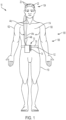
- the body 102 of the subject 100 can include any portion of the subject, including, for example, a head 104, a torso 106, or limbs (e.g., upper arms 108, thighs 110) of the subject.
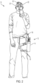
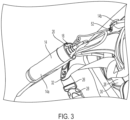
- the system 10 can comprise a carrier 12 having a carrier body 14 that defines a receiving space 16.
- An electric-signal generator 20 can be at least partially received within the receiving space 16 of the carrier body 14.
- the electric-signal generator 20 can be entirely received within the receiving space 16 of die carrier body 14.
- the electric-signal generator 20 can be only partially received within the receiving space 16 of the carrier body 14.
- the receiving space 16 can be configured to snugly receive the electric-signal generator 20 to inhibit movement thereof.
- the electric-signal generator 20 can be elongate (e.g., optionally, generally cylindrical and elongate along the height of the cylinder), and the receiving space 16 can be elongate relative to a longitudinal axis to receive the electric-signal generator 20.
- the receiving space 16 can have therein a retaining strap that secures (optionally, fixedly secures) the electric-signal generator 20 within the receiving space.
- the carrier 12 can further comprise a coupling apparatus 26 that is configured to fixedly couple the earner body 14 to a first location on the body 102 of the subject 100.
- the first location can be a thigh 110, a portion of the torso 106 (e.g., a waist 112 or a chest 114 or an annpit 116), or an upper arm 108 of the body 102 of the subject 100.
- the coupling apparatus can be configured to snugly retain the carrier body 14 against the body of the subject.
- the carrier body 14 cannot move (e.g., can move by no more than 5 cm in any direction) relative to the body of the subject without the subject intentionally moving the carrier body.
- the position of the carrier body 14 can stay substantially fixed on the body during daily activities. This is in contrast to conventional carriers that are meant to be carried by hand or worn loosely on the body and set down or removed during normal activities such as sitting in a chair or otherwise transitioning between seated and standing positions.
- the coupling apparatus 26 can comprise a belt 30, a strap 32, and/or a sleeve 34.
- the coupling apparatus 26 can comprise a clip, buckle, hook and loop, or other fastener 28.
- the clip, buckle, hook and loop material, or other fastener 28 can be configured to enable the coupling apparatus 26 to be selectively secured in a looped configuration or in an open configuration.
- the coupling apparatus 26 can comprise a strap adjuster that is configured to adjust an operative length of the coupling apparatus (e.g., the circumference of the belt, strap, or sleeve).
- the clip, buckle, hook and loop material, or other fastener 28 can serve as the strap adjuster.
- the coupling apparatus 26 can optionally be elastic (e.g., to allow elongation). In further aspects, the coupling apparatus 26 can be inelastic.
- the coupling apparatus 26 can comprise a belt 30 that is configured to extend around the torso 106 of the subject.
- the belt 30 can be configured to extend around the waist 112 of the subject (e.g., below the ribs of the subject and at or above the hips of the subject).
- the carrier 12 can be positioned at or above the waist 112 of the subject 100.
- the carrier body 14 can be positioned at the lower back, at one of the hips, or in front of the pelvis of the subject.
- the belt 30 can extend around the chest 114 of the subject (e.g., around or across the ribs of the subject),
- the carrier 12 can be positioned sufficiently high enough (relative to the waist) to ensure that the carrier (and the device) do not contact the legs of the subject when the subject transitions from a standing position to a seated position.
- the coupling apparatus 26 can comprise a strap 32 that is configured to extend around a thigh 110 of the subject.
- the carrier body 14 can optionally be positioned on the side or front of the thigh 110.
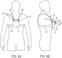
- the coupling apparatus 26 can comprise a strap 32 that is configured to extend over a shoulder of the subject and underneath an armpit on a side of the subject opposite the shoulder in order to position the carrier body 14 at the chest or within the armpit (and above the waist) of the subject.
- the carrier body 14 can be positioned underneath and/or at least partially within the armpit of the subject.
- the coupling apparatus 26 can comprise a torso strap 32a that extends around the torso (above the waist) of the subject and retains the carrier body 14 against the torso of the subject.
- the coupling apparatus 26 can further comprise at least one shoulder strap 32b that extends over at least one shoulder of the subject and distributes at least a portion of the weight of the carrier body 14 to the shoulder.
- the shoulder strap(s) 32b can couple to the torso strap 32a at first and second attachment points to the front and rear, respectively, of the carrier body 14.
- the shoulder strap 32b can couple to the carrier body 14.
- the carrier body 14 can be positioned on the chest of the subject.
- the coupling apparatus 26 can comprise a torso strap 32a that extends around the torso (above tire waist) of the subject and retains the carrier body 14 against the torso of the subject.
- the coupling apparatus 26 can further comprise a first shoulder strap 32b that extends over a first shoulder of the subject and distributes at least a portion of the weight of the carrier body 14 to the first shoulder.
- the coupling apparatus 26 can further comprise a second shoulder strap 32b that extends over a second shoulder of the subject and distributes at least a portion of the weight of the carrier body 14 to the second shoulder.
- Respective first ends of the first and second shoulder straps 32b can couple to the torso strap 32a, and respective second ends of the first and second shoulder straps can optionally couple to either the carrier body 14 or the torso strap 32a.
- the carrier body 14 can be configured to be held entirely above the lowest rib of the subject when worn by the subject.
- the carrier body can be configured to be held entirely below the neck of the subject when worn by the subject.
- the coupling apparatus 26 can comprise a sleeve 34.
- the sleeve 34 can be configured to extend around the thigh 110 of the subject.
- the sleeve 34 can be configured to extend around the upper arm 108 of the subject.
- the carrier 12 can comprise a belt 30 that is configured to extend around the waist of the body of the subject.
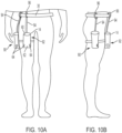
- the carrier housing 14 can hang from the belt 30 via a suspension strap 94 ( FIG. 10A ).
- the length of the suspension strap 94 can be adjustable.
- the carrier can further comprise a strap 32 that is configured to extend around the thigh of the body of the subject.
- at least one strap 32 e.g., an upper strap and a lower strap, as shown
- the belt 30, strap 32, or sleeve 34 can surround a body part (e.g., the leg, torso, or arm of the subject), and the carrier body 14 can be shifted about said body part (without decoupling the coupling apparatus from the subject) in order to adjust the position of the carrier body for different circumstances and environments.
- the carrier 12 can be worn about the waist of the subject.
- the carrier body 14 can be in a first position (e.g., positioned at the lower back of the subject), and, in further circumstances (e.g., when sitting), the carrier body can advantageously be in a second position (e.g., at a hip or in front of the pelvis of the subject).
- the carrier 12 can enable the subject to reposition the carrier body 14 between the first position and the second position.
- the carrier body 14 can be positioned on the front, side, rear, or inside of the thigh of the subject. For example, referring to FIGS.
- the carrier body 14 can be worn on in a first position 90 on an outside of the thigh of the subject. In some aspects, this position (on the outside of the thigh to avoid contact with the other thigh) can be advantageous for walking, etc. In some aspects, the carrier body 14 can be shifted from the first position 90 to a second position 92 that is on a front of the thigh of the subject. In some aspects, it is contemplated that this position (on the front of the thigh) can be advantageous for sitting in a chair with armrests, which could potentially contact the carrier body 14 in the first position on the outside of the thigh.
- both the carrier body 14 and the coupling apparatus 26 can shift together (e.g., rotate together relative to the subject).
- the carrier body 14 can shift (e.g., slide) relative to at least a portion of the coupling apparatus 26.
- the suspension strap 94 can couple to the belt 30 via a loop 96 so that the loop is slidable along the length of the belt.
- the carrier body can be movable along the length of the strap 32 around the thigh.
- the carrier body and strap 32 around the thigh can shift concurrently.
- the carrier body 14 can be positioned at one of the chest, armpit, the upper arm, or the thigh.
- the carrier body 14 can be positioned on the chest so that the carrier body is entirely above the rib cage and entirely below the neck (see FIGS. 9A-9B , for example).
- the carrier body 14 can be positioned on the chest so that the carrier body is positioned above the thighs of the body of the subject when the subject is seated.
- the carrier body can be positioned at the armpit sufficiently low so that the carrier body does not interfere with arm movement (see FIGS. 8A-8B , for example).
- the carrier body 14, when worn can be configured to be positioned below the pectoralis major of the subject.
- One or more transducer arrays 22 can be positioned on the body 102 of the subject 100.
- the one or more transducer arrays 22 can be positioned on or within the head 104 of the subject.
- the transducer arrays can be positioned on the torso 106 of the subject 100 (e.g., for treating lung cancer) or other portions of the body of the subject.
- the one or more transducer arrays 22 can be in communication with the electric-signal generator 20 via at least one electrical cable 24.
- Each of the transducer arrays 22 can comprise one or more transducers that are configured to emit TTFs in response to signals provided by the electric-signal generator 20.
- the one or more transducer arrays 22 can be positioned on the body 102 of the subject 100 at a second location that is different from the first location.
- the second location can be proximate to a treatment site.
- the second location can be on the head 104 of the subject 100.
- the second location can be a top of the head, a front of the head, a rear of the head, a side of the head, or an area that includes portions thereof.
- a transducer array can cover at least a portion of a top, front, rear, and sides of the head of the subject as illustrated in FIG. 1 .
- the second location can be on the torso of the subject.
- the second location can be on a front, a back, or a side of the torso.
- the transducer arrays 22 can be position anywhere on the body of the subject.
- each transducer array 22 can be at a respective second location, wherein each respective second location is different from the first location.
- die respective second locations on the body can be opposed sides of the head (e.g., left and right sides or front and back sides of the head).
- the respective second locations on the body can be on the torso (e.g., on front and rear sides of the torso).
- the second location of at least one transducer array 22 can be on the torso of the body of the subject, and the second location of at least one additional transducer array 20 can be on a head of the body of the subject.
- the system 10 can comprise an electrical connection box 40.
- the electrical connection box 40 can provide electrical communication (and a physical coupling) between the one or more transducer arrays 22 and the electric-signal generator 20.
- the at least one electrical cable 24 can comprise a first electrical cable 42 that extends between and couples to the electric-signal generator 20 and the electrical connection box.
- a respective second electrical cable e.g., electrical cables 44a, 44b, 44c
- each transducer array 22 e.g., transducer array 22a, 22b, 22c.
- the electrical connection box 40 can serve as a junction box that can enable the electric-signal generator 20 to deliver different electric signals to the different transducer arrays 22.
- the electrical connection box 40 can have a first side 46 and an opposing second side 48.
- the first side 46 can define a first port 50 that couples to the first electrical cable 42
- the second side 48 can define at least one second port 52 that couples to the second electrical cable (e.g., the electrical cables 44a, 44b, 44c).
- at least one electrical cable can be integral to the electrical connection box 40.
- the first electrical cable 42 can be integral or permanently physically coupled to the electrical connection box 40 through the first port 50.
- both the first port 50 and the second port(s) 52 can be on the same first side 46 of the electrical connection box.
- all of the electrical cables can extend from the electrical connection box in the same direction so that the electrical connection box 40 can be inserted into a receiving space with all the electrical cables exiting out a single opening of the carrier body 14 without significant bends (e.g., 90 degrees or more) in any of the electrical cables.
- the electrical connection box 40 can be omitted, and the electrical cable(s) 24 can extend directly from the electric-signal generator 20 to the transducer array(s) 22.
- the electrical connection box 40 can couple to the carrier 12.
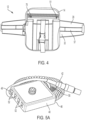
- the system 10 can comprise a clip 53 that couples the electrical connection box to the carrier 12.
- the clip 53 can couple the electrical connection box 40 to the belt 30 or other coupling apparatus 26.
- the clip 53 can comprise a member that is rotationally biased against a surface (e.g., of the electrical connection box 40) by a torsion spring 55.
- die coupling apparatus 26 can define a loop 57 ( FIG. 4 ) that can receive the clip 53.
- the electrical connection box 40 can be received within the carrier 12.
- the receiving space 16 can be a first receiving space
- the carrier 12 can define a second receiving space 51.
- the carrier 14 can comprise at least a first carrier body 14a and a second carrier body 14b, wherein the first carrier body defines the first receiving space 16, and the second carrier body defines the second receiving space 51.
- the carrier body 14 can define both the first and second receiving spaces 16, 5.1.
- the electrical connection box 40 can be received within the second receiving space 51.
- the carrier can define at least one pocket 70 ( FIG. 4 ).
- the pocket(s) 70 can be separate from the receiving space(s).
- the carrier body 14 can have an inner surface 60 and an outer surface 62.
- the inner surface 60 of the carrier body 14 can define the receiving space 16.
- the carrier body 14 can further define at least one opening 64 that extends between the inner surface 60 and the outer surface 62.
- the opening(s) 64 can be in communication with the receiving space of the carrier body and can be configured to permit dissipation of heat from the electric-signal generator 20.
- the carrier body can define a single opening 64.
- the carrier body can define 2, 3, 4, or more openings 64.
- the opening(s) 64 can be, for example, on the side(s) of the carrier body 14 and/or on the bottom of the carrier body.
- a penneable cover such as a grate, screen, or perforated material, can cover the one or more openings 64 while permitting air to pass therethrough.
- the carrier 12 can comprise a cover 66 that couples to the carrier body 14 and extends over at least a portion of the receiving space 16 of the carrier body.
- the cover 66 can inhibit liquid or other undesirable elements (e.g., food crumbs, dust, etc.) from entering the receiving space.
- the carrier body can define a top opening 68 to permit the electric-signal generator to be inserted into and removed from the carrier, and the cover 66 can extend across the top opening when in a closed position 84.
- the cover 66 can pivotably couple to the carrier body 14 (e.g., via a hinge or flexible coupling).
- the cover can couple to the carrier body via any suitable fastener(s) 80 (e.g., a zipper or one or more buttons, clips, etc.) to retain the cover 66 in the closed position 84.
- the cover 66 can be retained in an open position 86.
- the carrier 12 can comprise a fastener 82 (e.g., hook and loop material, a snap, or one or more magnets) that retains the cover 66 in the open position 86.
- the cover 66 can be spring biased toward the open position 86 or locked in the open position via a releasable mechanical catch.
- the cover 66 can comprise a lip 88 that extends below the top opening 68 relative to a vertical axis when the cover 66 is in the closed position 84.
- the carrier body 14 can define at least one coupling element that enables different coupling apparatuses to be attached thereto and removed therefrom.
- the coupling element can complise, for example, a loop through which the strap 30 or the belt 32 can be inserted.
- the coupling element can comprise a carabineer, a clip (e.g., a double side release buckle), and/or one of a hook or loop fastener that is configured to engage the other of the hook or loop fastener of the coupling apparatus 26.
- the carrier 12 disclosed herein is configured to remain on the person during daily activities such as sitting, standing, walking, exercising, etc.
- the length of the electrical cable(s) can be reduced to the length necessary to allow unrestricted movement of the subject, without having excess length that can serve as a tripping hazard or get caught on a snag.
- the length of the longest electrical cable of the electrical cable(s) 24 can be no more than 20 cm longer than the distance from the carrier to the farthest electrode array from the carrier as measured along a path against the body of the subject.
- the length of the electrical cable 24 can be the sum of the lengths of the first electrical cable 42, the (longest) second electrical cable(s), and the distance between the first and second ports 50, 52.
- the reduced length of the electrical cables as compared to conventional systems can further reduce the weight of the electrical cables.
- excess cable length can be received within the carrier 12.
- the excess length of the cables can be received within the first receiving space 16.
- the excess length of cables can be received within the second receiving space 51.
- the system can comprise at least one retention strap (or band or wire tie) that is configured to secure the excess cable length in a rolled, folded, or bunched configuration.
- the excess length of cable can be folded against itself one or more times to define a plurality of adjacent cable segments, and the retention strap can be wrapped around the plurality of adjacent cable segments.
- die retention strap can comprise a fastener (e.g., hook and loop material, a snap fastener, or a clip that retains the retention strap in a looped configuration.
- the retention strap can comprise a semi-rigid member (e.g., as in a twist tie) that enables the retention strap to stay wrapped around the excess length of cable.
- the retention strap can optionally be coupled to the carrier 12.
- the retention strap can be separate from, and not coupled to, the carrier 12.
- a kit can comprise a carrier body 14 as disclosed herein and a plurality of coupling apparatuses 26.
- each of the coupling apparatuses 26 can be selectively attached to, or decoupled from, the carrier body 14. In this way, the subject can select between the different coupling apparatuses depending on the coupling apparatus and desired position of the carrier body.
- the electric-signal generator 20 can comprise a portable power source, such as a battery.
- a spare battery 74 can be positioned within one pocket 70 of the carrier. The spare battery 74 can be used to replace a depleted battery of the electric-signal generator 20.
- Embodiments disclosed herein can enable subjects receiving TTF therapy to be mobile and active during treatment.
- the carrier 12 does not have to be picked up and held.
- the subject does not have to constantly pay attention to the location of the carrier.
- embodiments disclosed herein can be more discrete as compared to the conventional luggage-resembling carrier.
- the carrier 12 can have a much more subtle profile that draws less attention than the conventional carrier.
- the carrier 12 can be worn underneath clothes, and the electrical cables can similarly be run underneath the clothes so that little or none of the system 10 is visible to an onlooker.
- a carrier 12 as described herein can be fixedly coupled to the body of the subject 100 at a first location.
- a strap can be positioned across at least a portion of the torso of the body of the subject or at least an upper arm of the body of the subject or around a thigh of the body of the subject.
- a belt can be positioned around the torso of the body of the subject.
- a sleeve can be positioned around the upper arm or thigh of the subject.
- the electric-signal generator 20 can be positioned within the receiving space 16 of the carrier body 14 of the carrier 12.
- Each transducer array 22 can be securely placed at a respective second location on the body of the subject, wherein the first location is different from the second location.
- each transducer array of the plurality of transducer arrays can be positioned at the respective second location before the carrier is fixedly coupled to the first location of the body.
- the second location(s) can be determined by a computing device 1001.
- the computing device 1001 can instruct a subject or clinician as to the proper positioning for each transducer array.
- the computing device can receive (e.g., via clinician input) information regarding the region to be treated, such as, for example, a location of a tumor within the body. Based on the position and the anatomy of the patient, the computing device can determine the proper positioning for each transducer array and provide an output indicative of the proper positioning for each transducer array.
- the computing device 1001 can determine at least one placement location on the body of the subject where the carrier can be fixedly coupled to avoid overlapping any portion of the plurality of transducer arrays. In some aspects, based on placement locations of the transducer arrays, the computing device can provide locations for positioning the carrier body 14 in which the carrier body is spaced from the transducer arrays (e.g., so that the transducer array is not between the carrier body and the subject). In this way, excess heat in one location on the body of the subject can be minimized.
- the computing device can provide recommendations of the armpit, the upper arms, or the thighs of the body of the subject as locations for placement of the carrier body 14.
- the computing device can be in communication with a display, and the computing device can cause the display to provide an output indicative of the placement location(s) on the body where the carrier can be fixedly coupled to avoid overlapping any portion of the plurality of transducer arrays.
- the display can output a list of locations or a graphic.
- the computing device can further provide an output indicative of which coupling apparatus or coupling apparatuses can be used to fixedly couple die carrier to the body in said placement location(s).
- the computing device 1001 can user the determined proper positioning for each transducer array in order to determine the at least one placement location on the body of the subject where the carrier can be fixedly coupled to avoid overlapping any portion of the plurality of transducer arrays.
- the computing device can be configured to receive a user input of the location of each transducer array in order to determine the at least one placement location on the body of the subject where the carrier can be fixedly coupled to avoid overlapping any portion of the plurality of transducer arrays.
- die computing device can provide a prompt (e.g., on a display) for a user to input the location of each transducer array, and user (e.g., a clinician) can input, via an input device of the computing device, the location of each transducer array.
- a prompt e.g., on a display
- user e.g., a clinician
- the transducer arrays 22 can be coupled to the electric-signal transducer 20.
- the second electrical cables (e.g., electrical cables 44a, 44b, 44c) of the respective transducer arrays can be coupled to the electrical connection box, and the electric-signal generator 20 can be coupled to the electrical connection box 40 via the first electrical cable 42, thereby providing electrical communication between the electric-signal generator and the transducer array(s).
- the electrical connection box 40 can be clipped to the carrier (e.g., to the belt 32) or positioned within the carrier (e.g., within the receiving space 16).
- the electric-signal generator 20 can be used to deliver electrical signals to the transducer array(s) 22, and the transducer array(s) can generate TTFs.
- U.S. Patent No. 7,565,205, granted July 21, 2009 describes further details for generating and using TTFs to treat cancer.
- delivery of the electrical signals to the transducer array(s) 22 can be ceased.
- the carrier can be coupled to the subject with a different coupling apparatus.
- the coupling apparatus can be decoupled from the body of the subject.
- the coupling apparatus can initially be coupled to the body of the subject with a first coupling apparatus, and a second coupling apparatus that is different from the first coupling apparatus can also be used to couple the carrier to the body of the subject.
- the first coupling apparatus can be decoupled from the carrier body prior to coupling the second coupling apparatus to the carrier body (such that the first coupling apparatus and the second coupling apparatus sequentially couple to the carrier body).
- the carrier can be positioned in a third position that is different from the first position and the second position.
- the second coupling apparatus can differ from the first coupling apparatus in fastener type, coupling location, and/or size.
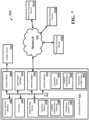
- FIG. 7 shows a system 1000 including an exemplary configuration of a computing device 1001 for use with the system 10 disclosed herein.
- the computing device 1001 can be integral to the system 10.
- the computing device 1001 can be a separate computing device, such as, for example, a tablet, smartphone, laptop, or desktop computer can communicate with the system 10 and can enable the subject to interface with the system 10.
- the computing device 1001 may comprise one or more processors 1003, a system memory 1012, and a bus 1013 that couples various components of the computing device 1001 including the one or more processors 1003 to the system memory 1012. In the case of multiple processors 1003, the computing device 1001 may utilize parallel computing.
- the bus 1013 may comprise one or more of several possible types of bus structures, such as a memory bus, memory controller, a peripheral bus, an accelerated graphics port, and a processor or local bus using any of a variety of bus architectures.
- the computing device 1001 may operate on and/or comprise a variety of computer readable media (e.g., non-transitory).
- Computer readable media may be any available media that is accessible by the computing device 1001 and comprises, non-transitory, volatile and/or non-volatile media, removable and non-removable media.
- the system memory 1012 has computer readable media in the form of volatile memory, such as random access memory (RAM), and/or non-volatile memory, such as read only memory (ROM).
- the system memory 1012 may store data such as transducer location data 1007 (i.e., data from signals received by the electrodes) and/or program modules such as operating system 1005 and location determination software 1006 that are accessible to and/or are operated on by the one or more processors 1003.
- the computing device 1001 may also comprise other removable/non-removable, volatile/non-volatile computer storage media.
- the mass storage device 1004 may provide non-volatile storage of computer code, computer readable instructions, data structures, program modules, and other data for the computing device 1001.
- the mass storage device 1004 may be a hard disk, a removable magnetic disk, a removable optical disk, magnetic cassettes or other magnetic storage devices, flash memory cards, CD-ROM, digital versatile disks (DVD) or other optical storage, random access memories (RAM), read only memories (ROM), electrically erasable programmable read-only memory (EEPROM), and the like.
- Transducer location data 1007 may also be stored on the mass storage device 1004.
- Transducer location data 1007 may be stored in any of one or more databases known in the art. The databases may be centralized or distributed across multiple locations within the network 1015.
- a user may enter commands and information into the computing device 1001 using an input device (not shown).
- input devices comprise, but are not limited to, a keyboard, touchscreen display, pointing device (e.g., a computer mouse, remote control), a microphone, a joystick, a scanner, tactile input devices such as gloves, and other body coverings, motion sensor, speech recognition, and the like.
- a human machine interface 1002 that is coupled to the bus 1013, but may be connected by other interface and bus structures, such as a parallel port, game port, an IEEE 1394 Port (also known as a Firewire port), a serial port, network adapter 1008, and/or a universal serial bus (USB).
- a display device 1011 may also be connected to the bus 1013 using an interface, such as a display adapter 1009. It is contemplated that the computing device 1001 may have more than one display adapter 1009 and the computing device 1001 may have more than one display device 1011.
- a display device 1011 may be a monitor, an LCD (Liquid Crystal Display), light emitting diode (LED) display, television, smart lens, smart glass, and/ or a projector.
- other output peripheral devices may comprise components such as speakers (not shown) and a printer (not shown) which may be connected to the computing device 1001 using Input/Output Interface 1010. Any step and/or result of the methods may be output (or caused to be output) in any form to an output device.
- Such output may be any form of visual representation, including, but not limited to, textual, graphical, animation, audio, tactile, and the like.
- the display 1011 and computing device 1001 may be part of one device, or separate devices.
- the computing device 1001 may operate in a networked environment using logical connections to one or more remote computing devices 1014a,b,c.
- a remote computing device 1014a,b,c may be a personal computer, computing station (e.g., workstation), portable computer (e.g., laptop, mobile phone, tablet device), smart device (e.g., smartphone, smart watch, activity tracker, smart apparel, smart accessory), security and/or monitoring device, a server, a router, a network computer, a peer device, edge device or other common network node, and so on.
- Logical connections between the computing device 1001 and a remote computing device 1014a,b,c may be made using a network 1015, such as a local area network (LAN) and/or a general wide area network (WAN) , or a Cloud-based network. Such network connections may be through a network adapter 1008.
- a network adapter 1008 may be implemented in both wired and wireless environments. Such networking environments arc conventional and commonplace in dwellings, offices, enterprise-wide computer networks, intranets, and the Internet.
- the remote computing devices 1014a,b,c can optionally have some or all of the components disclosed as being part of computing device 1001.
- it is contemplated that some or all aspects of data processing described herein can be performed via cloud computing on one or more servers or other remote computing devices. Accordingly, at least a portion of the system 1000 can be configured with internet connectivity.
Landscapes
- Health & Medical Sciences (AREA)
- Radiology & Medical Imaging (AREA)
- Animal Behavior & Ethology (AREA)
- Engineering & Computer Science (AREA)
- Biomedical Technology (AREA)
- Nuclear Medicine, Radiotherapy & Molecular Imaging (AREA)
- Veterinary Medicine (AREA)
- Life Sciences & Earth Sciences (AREA)
- Public Health (AREA)
- General Health & Medical Sciences (AREA)
- Oncology (AREA)
- Hospice & Palliative Care (AREA)
- Percussion Or Vibration Massage (AREA)
- Surgical Instruments (AREA)
- Electrotherapy Devices (AREA)
Claims (15)
- System zum Anlegen von Tumorbehandlungsfeldern an einen Abschnitt eines Körpers eines Subjekts, wobei das System umfasst:einen Träger (12), umfassend einen Trägerkörper (14), der einen Aufnahmeraum (16) definiert, und eine Kupplungseinrichtung (26), die konfiguriert ist, um den Trägerkörper (14) an einer ersten Stelle an dem Körper des Subjekts fest zu koppeln;einen elektrischen Signalgenerator (20), der mindestens teilweise in dem Aufnahmeraum (16) des Trägerkörpers (14) aufgenommen ist; undmindestens eine Wandleranordnung (22) in elektrischer Kommunikation mit dem elektrischen Signalgenerator (20);dadurch gekennzeichnet, dass die erste Stelle eine von einem Oberschenkel, einer Brust, einem Oberarm oder einer Achselhöhle des Körpers des Subjekts ist, und jede Wandleranordnung (22) zur sicheren Platzierung an einer jeweiligen zweiten Stelle auf dem Körper des Subjekts, die sich von der ersten Stelle unterscheidet, konfiguriert ist.
- System nach Anspruch 1, wobei die Kopplungseinrichtung (26) einen Riemen (32) umfasst, der zum Positionieren über mindestens einen Abschnitt eines Oberkörpers des Körpers des Subjekts oder um den Oberarm des Körpers des Subjekts konfiguriert ist.
- System nach Anspruch 1, wobei die Kopplungseinrichtung (26) einen Gurt (30) umfasst.
- System nach Anspruch 1, wobei die Kopplungseinrichtung (26) eine Hülse (34) umfasst, die zum Positionieren um den Oberarm des Körpers des Subjekts oder um den Oberschenkel des Körpers des Subjekts konfiguriert ist.
- System nach Anspruch 1, wobei die Kopplungseinrichtung (26) einen Gurt (30) und einen Riemen (32), der an den Trägerkörper (14) und den Gurt (30) gekoppelt ist und sich zwischen diesen erstreckt, umfasst.
- System nach Anspruch 1, weiter umfassend:
ein elektrisches Kabel (24), das elektrische Kommunikation zwischen dem elektrischen Signalgenerator (20) und der mindestens einen Wandleranordnung (22) bereitstellt. - System nach Anspruch 1, weiter umfassend:einen elektrischen Anschlusskasten (40);ein erstes elektrisches Kabel (42), das elektrische Kommunikation zwischen dem elektrischen Signalgenerator (20) und dem elektrischen Anschlusskasten (40) bereitstellt; undmindestens ein zweites elektrisches Kabel (44a-c), das elektrische Kommunikation zwischen dem elektrischen Anschlusskasten (40) und der mindestens einen Wandleranordnung (22) bereitstellt.
- System nach Anspruch 7, wobei die Kopplungseinrichtung (26) einen Gurt (30), einen Riemen (32), der an den Trägerkörper (14) und den Gurt (30) gekoppelt ist und sich zwischen diesen erstreckt, und einen Clip (53) umfasst, der den elektrischen Anschlusskasten (40) an den Gurt (30) koppelt.
- System nach Anspruch 8, wobei der elektrische Anschlusskasten (40) mindestens teilweise in dem Aufnahmeraum (16) des Trägerkörpers (14) aufgenommen ist.
- System nach Anspruch 7, wobei der Träger (12) weiter einen zweiten Aufnahmeraum (51) umfasst, der mindestens teilweise den elektrischen Anschlusskasten (40) aufnimmt.
- System nach Anspruch 7, wobei der elektrische Anschlusskasten (40) gegenüberliegende erste und zweite Seiten (46, 48) aufweist, wobei die erste Seite (46) einen ersten und einen zweiten elektrischen Anschluss (50, 52) definiert und das erste elektrische Kabel (42) an den ersten elektrischen Anschluss (50) gekoppelt ist und das zweite elektrische Kabel (44a-c) an den zweiten elektrischen Anschluss (52) gekoppelt ist.
- System nach Anspruch 3, wobei der Gurt (30) zum Positionieren um einen Abschnitt eines Oberkörpers des Körpers des Subjekts konfiguriert ist.
- System nach Anspruch 1, wobei der Trägerkörper (14) eine innere und eine äußere Oberfläche (60, 62) aufweist, wobei die innere Oberfläche (60) den Aufnahmeraum (16) des Trägerkörpers (14) definiert und der Trägerkörper (14) weiter eine Öffnung (64) definiert, die sich zwischen der inneren und der äußeren Oberfläche (60, 62) erstreckt, wobei die Öffnung (64) in Kommunikation mit dem Aufnahmeraum (16) steht und konfiguriert ist, um die Ableitung von Wärme aus dem elektrischen Signalgenerator (20) zu ermöglichen.
- System nach Anspruch 1, wobei die zweite Stelle auf einem Kopf des Körpers des Subjekts ist.
- Kit, umfassend ein System nach einem der Ansprüche 1 bis 14, wobei der Träger (12) weiter mindestens eine zweite Kopplungseinrichtung (26) umfasst, die zum selektiven entfernbaren Koppeln an den Trägerkörper (14) konfiguriert ist, wobei jede der ersten und der zweiten Kopplungseinrichtung (26) konfiguriert ist, um Koppeln des Trägerkörpers (14) an eine unterschiedliche Stelle des Körpers des Subjekts zu ermöglichen.
Applications Claiming Priority (2)
| Application Number | Priority Date | Filing Date | Title |
|---|---|---|---|
| US202163168416P | 2021-03-31 | 2021-03-31 | |
| PCT/IB2022/052951 WO2022208390A1 (en) | 2021-03-31 | 2022-03-30 | Carrier for elements of tumor-treating field provision system and systems and methods of using same |
Publications (3)
| Publication Number | Publication Date |
|---|---|
| EP4284493A1 EP4284493A1 (de) | 2023-12-06 |
| EP4284493C0 EP4284493C0 (de) | 2024-12-04 |
| EP4284493B1 true EP4284493B1 (de) | 2024-12-04 |
Family
ID=81327695
Family Applications (1)
| Application Number | Title | Priority Date | Filing Date |
|---|---|---|---|
| EP22715385.5A Active EP4284493B1 (de) | 2021-03-31 | 2022-03-30 | Träger für elemente eines tumorbehandlungsfeldbereitstellungssystems sowie systeme und verfahren zur verwendung davon |
Country Status (6)
| Country | Link |
|---|---|
| US (2) | US20220314014A1 (de) |
| EP (1) | EP4284493B1 (de) |
| JP (1) | JP2024511868A (de) |
| CN (1) | CN117157123A (de) |
| TW (1) | TW202241545A (de) |
| WO (1) | WO2022208390A1 (de) |
Families Citing this family (2)
| Publication number | Priority date | Publication date | Assignee | Title |
|---|---|---|---|---|
| US20240216706A1 (en) * | 2022-12-28 | 2024-07-04 | Novocure Gmbh | Wearable garment with integrated tumor treating fields voltage generator |
| SE2350148A1 (en) * | 2023-02-15 | 2024-08-16 | Force Oncology Ab | Wearable electrical apparatus with replaceable combined power source and heat sink module |
Family Cites Families (11)
| Publication number | Priority date | Publication date | Assignee | Title |
|---|---|---|---|---|
| US5078134A (en) * | 1988-04-25 | 1992-01-07 | Lifecor, Inc. | Portable device for sensing cardiac function and automatically delivering electrical therapy |
| US6065154A (en) * | 1998-04-07 | 2000-05-23 | Lifecor, Inc. | Support garments for patient-worn energy delivery apparatus |
| US8447395B2 (en) * | 2000-02-17 | 2013-05-21 | Novocure Ltd | Treating bacteria with electric fields |
| US6868289B2 (en) * | 2002-10-02 | 2005-03-15 | Standen Ltd. | Apparatus for treating a tumor or the like and articles incorporating the apparatus for treatment of the tumor |
| US7599745B2 (en) | 2000-02-17 | 2009-10-06 | Standen Ltd | Treating a tumor or the like with an electric field |
| US7146210B2 (en) * | 2000-02-17 | 2006-12-05 | Standen Ltd. | Apparatus and method for optimizing tumor treatment efficiency by electric fields |
| US20050043655A1 (en) * | 2003-08-18 | 2005-02-24 | David Schenck | Back support device |
| US12420083B2 (en) * | 2012-06-26 | 2025-09-23 | Exoneural Network Ab | Medical therapy arrangement for applying an electrical stimulation to a human or animal subject |
| US11071875B2 (en) * | 2018-02-20 | 2021-07-27 | University Of Iowa Research Foundation | Therapeutic systems using magnetic and electric fields |
| WO2020069308A1 (en) * | 2018-09-28 | 2020-04-02 | Zoll Medical Corporation | Adhesively coupled wearable medical device |
| CN120393288A (zh) * | 2020-08-28 | 2025-08-01 | 江苏海莱新创医疗科技有限公司 | 可穿戴电场施加装置 |
-
2022
- 2022-03-30 JP JP2023560684A patent/JP2024511868A/ja active Pending
- 2022-03-30 CN CN202280026164.4A patent/CN117157123A/zh active Pending
- 2022-03-30 US US17/708,482 patent/US20220314014A1/en not_active Abandoned
- 2022-03-30 EP EP22715385.5A patent/EP4284493B1/de active Active
- 2022-03-30 TW TW111112277A patent/TW202241545A/zh unknown
- 2022-03-30 WO PCT/IB2022/052951 patent/WO2022208390A1/en not_active Ceased
-
2025
- 2025-11-24 US US19/398,946 patent/US20260077206A1/en active Pending
Also Published As
| Publication number | Publication date |
|---|---|
| TW202241545A (zh) | 2022-11-01 |
| US20220314014A1 (en) | 2022-10-06 |
| EP4284493C0 (de) | 2024-12-04 |
| EP4284493A1 (de) | 2023-12-06 |
| JP2024511868A (ja) | 2024-03-15 |
| CN117157123A (zh) | 2023-12-01 |
| WO2022208390A1 (en) | 2022-10-06 |
| US20260077206A1 (en) | 2026-03-19 |
Similar Documents
| Publication | Publication Date | Title |
|---|---|---|
| US20260077206A1 (en) | Carrier For Elements Of Tumor-Treating Field Provision System And Systems And Methods Of Using Same | |
| US11484710B2 (en) | Device and system for real-time gait modulation and methods of operation thereof | |
| CN111407249B (zh) | 可穿戴医疗装置 | |
| US20220338782A1 (en) | Modular garment for a wearable medical device | |
| US20220331194A1 (en) | Therapeutic undergarments for the treatment of functional gastrointestinal disorders including irritable bowel syndrome | |
| US11896545B2 (en) | Vibrating garment assembly | |
| EP0948972A3 (de) | Stützbekleidung für eine von einem Patienten tragbare Energieabgabevorrichtung | |
| US12383458B2 (en) | Medical vest and using method thereof | |
| HK40095948B (en) | Carrier for elements of tumor-treating field provision system and systems and methods of using same | |
| HK40095948A (en) | Carrier for elements of tumor-treating field provision system and systems and methods of using same | |
| US12420052B2 (en) | Vibration suppression apparatus | |
| KR102710189B1 (ko) | 센서가 구비된 ems 운동기기 시스템 | |
| US12629516B2 (en) | Device and system for real-time gait modulation and methods of operation thereof | |
| CN109938426A (zh) | 一种具有电磁转换结构的防摔服 | |
| KR20260006659A (ko) | 사용자의 신경학적 질환의 증상을 완화하기 위한 웨어러블 장치 및 그 사용 방법 | |
| GB2630564A (en) | Wearable device for mitigating symptoms of neurological conditions of users and methods for using same | |
| GB2630141A (en) | Wearable device for mitigating symptoms of neurological conditions of users and method for using same |
Legal Events
| Date | Code | Title | Description |
|---|---|---|---|
| STAA | Information on the status of an ep patent application or granted ep patent |
Free format text: STATUS: UNKNOWN |
|
| STAA | Information on the status of an ep patent application or granted ep patent |
Free format text: STATUS: THE INTERNATIONAL PUBLICATION HAS BEEN MADE |
|
| PUAI | Public reference made under article 153(3) epc to a published international application that has entered the european phase |
Free format text: ORIGINAL CODE: 0009012 |
|
| STAA | Information on the status of an ep patent application or granted ep patent |
Free format text: STATUS: REQUEST FOR EXAMINATION WAS MADE |
|
| 17P | Request for examination filed |
Effective date: 20230830 |
|
| AK | Designated contracting states |
Kind code of ref document: A1 Designated state(s): AL AT BE BG CH CY CZ DE DK EE ES FI FR GB GR HR HU IE IS IT LI LT LU LV MC MK MT NL NO PL PT RO RS SE SI SK SM TR |
|
| REG | Reference to a national code |
Ref country code: HK Ref legal event code: DE Ref document number: 40095948 Country of ref document: HK |
|
| GRAP | Despatch of communication of intention to grant a patent |
Free format text: ORIGINAL CODE: EPIDOSNIGR1 |
|
| STAA | Information on the status of an ep patent application or granted ep patent |
Free format text: STATUS: GRANT OF PATENT IS INTENDED |
|
| DAV | Request for validation of the european patent (deleted) | ||
| DAX | Request for extension of the european patent (deleted) | ||
| GRAS | Grant fee paid |
Free format text: ORIGINAL CODE: EPIDOSNIGR3 |
|
| INTG | Intention to grant announced |
Effective date: 20240710 |
|
| RIN1 | Information on inventor provided before grant (corrected) |
Inventor name: LEONARD II, FRANCIS X. |
|
| GRAA | (expected) grant |
Free format text: ORIGINAL CODE: 0009210 |
|
| STAA | Information on the status of an ep patent application or granted ep patent |
Free format text: STATUS: THE PATENT HAS BEEN GRANTED |
|
| AK | Designated contracting states |
Kind code of ref document: B1 Designated state(s): AL AT BE BG CH CY CZ DE DK EE ES FI FR GB GR HR HU IE IS IT LI LT LU LV MC MK MT NL NO PL PT RO RS SE SI SK SM TR |
|
| REG | Reference to a national code |
Ref country code: CH Ref legal event code: EP |
|
| REG | Reference to a national code |
Ref country code: DE Ref legal event code: R096 Ref document number: 602022008438 Country of ref document: DE |
|
| REG | Reference to a national code |
Ref country code: IE Ref legal event code: FG4D |
|
| U01 | Request for unitary effect filed |
Effective date: 20250102 |
|
| U07 | Unitary effect registered |
Designated state(s): AT BE BG DE DK EE FI FR IT LT LU LV MT NL PT RO SE SI Effective date: 20250114 |
|
| PG25 | Lapsed in a contracting state [announced via postgrant information from national office to epo] |
Ref country code: HR Free format text: LAPSE BECAUSE OF FAILURE TO SUBMIT A TRANSLATION OF THE DESCRIPTION OR TO PAY THE FEE WITHIN THE PRESCRIBED TIME-LIMIT Effective date: 20241204 |
|
| PG25 | Lapsed in a contracting state [announced via postgrant information from national office to epo] |
Ref country code: ES Free format text: LAPSE BECAUSE OF FAILURE TO SUBMIT A TRANSLATION OF THE DESCRIPTION OR TO PAY THE FEE WITHIN THE PRESCRIBED TIME-LIMIT Effective date: 20241204 |
|
| PG25 | Lapsed in a contracting state [announced via postgrant information from national office to epo] |
Ref country code: NO Free format text: LAPSE BECAUSE OF FAILURE TO SUBMIT A TRANSLATION OF THE DESCRIPTION OR TO PAY THE FEE WITHIN THE PRESCRIBED TIME-LIMIT Effective date: 20250304 |
|
| PG25 | Lapsed in a contracting state [announced via postgrant information from national office to epo] |
Ref country code: GR Free format text: LAPSE BECAUSE OF FAILURE TO SUBMIT A TRANSLATION OF THE DESCRIPTION OR TO PAY THE FEE WITHIN THE PRESCRIBED TIME-LIMIT Effective date: 20250305 |
|
| PG25 | Lapsed in a contracting state [announced via postgrant information from national office to epo] |
Ref country code: RS Free format text: LAPSE BECAUSE OF FAILURE TO SUBMIT A TRANSLATION OF THE DESCRIPTION OR TO PAY THE FEE WITHIN THE PRESCRIBED TIME-LIMIT Effective date: 20250304 |
|
| U20 | Renewal fee for the european patent with unitary effect paid |
Year of fee payment: 4 Effective date: 20250325 |
|
| RAP4 | Party data changed (patent owner data changed or rights of a patent transferred) |
Owner name: NOVOCURE GMBH |
|
| U1H | Name or address of the proprietor changed after the registration of the unitary effect |
Owner name: NOVOCURE GMBH; CH |
|
| PG25 | Lapsed in a contracting state [announced via postgrant information from national office to epo] |
Ref country code: SM Free format text: LAPSE BECAUSE OF FAILURE TO SUBMIT A TRANSLATION OF THE DESCRIPTION OR TO PAY THE FEE WITHIN THE PRESCRIBED TIME-LIMIT Effective date: 20241204 |
|
| PG25 | Lapsed in a contracting state [announced via postgrant information from national office to epo] |
Ref country code: PL Free format text: LAPSE BECAUSE OF FAILURE TO SUBMIT A TRANSLATION OF THE DESCRIPTION OR TO PAY THE FEE WITHIN THE PRESCRIBED TIME-LIMIT Effective date: 20241204 |
|
| PG25 | Lapsed in a contracting state [announced via postgrant information from national office to epo] |
Ref country code: IS Free format text: LAPSE BECAUSE OF FAILURE TO SUBMIT A TRANSLATION OF THE DESCRIPTION OR TO PAY THE FEE WITHIN THE PRESCRIBED TIME-LIMIT Effective date: 20250404 |
|
| PG25 | Lapsed in a contracting state [announced via postgrant information from national office to epo] |
Ref country code: SK Free format text: LAPSE BECAUSE OF FAILURE TO SUBMIT A TRANSLATION OF THE DESCRIPTION OR TO PAY THE FEE WITHIN THE PRESCRIBED TIME-LIMIT Effective date: 20241204 |
|
| PG25 | Lapsed in a contracting state [announced via postgrant information from national office to epo] |
Ref country code: CZ Free format text: LAPSE BECAUSE OF FAILURE TO SUBMIT A TRANSLATION OF THE DESCRIPTION OR TO PAY THE FEE WITHIN THE PRESCRIBED TIME-LIMIT Effective date: 20241204 |
|
| PLBE | No opposition filed within time limit |
Free format text: ORIGINAL CODE: 0009261 |
|
| STAA | Information on the status of an ep patent application or granted ep patent |
Free format text: STATUS: NO OPPOSITION FILED WITHIN TIME LIMIT |
|
| PG25 | Lapsed in a contracting state [announced via postgrant information from national office to epo] |
Ref country code: MC Free format text: LAPSE BECAUSE OF FAILURE TO SUBMIT A TRANSLATION OF THE DESCRIPTION OR TO PAY THE FEE WITHIN THE PRESCRIBED TIME-LIMIT Effective date: 20241204 |
|
| REG | Reference to a national code |
Ref country code: CH Ref legal event code: L10 Free format text: ST27 STATUS EVENT CODE: U-0-0-L10-L00 (AS PROVIDED BY THE NATIONAL OFFICE) Effective date: 20251015 |
|
| REG | Reference to a national code |
Ref country code: CH Ref legal event code: H13 Free format text: ST27 STATUS EVENT CODE: U-0-0-H10-H13 (AS PROVIDED BY THE NATIONAL OFFICE) Effective date: 20251024 |
|
| 26N | No opposition filed |
Effective date: 20250905 |
|
| PG25 | Lapsed in a contracting state [announced via postgrant information from national office to epo] |
Ref country code: CH Free format text: LAPSE BECAUSE OF NON-PAYMENT OF DUE FEES Effective date: 20250331 |
|
| PG25 | Lapsed in a contracting state [announced via postgrant information from national office to epo] |
Ref country code: IE Free format text: LAPSE BECAUSE OF NON-PAYMENT OF DUE FEES Effective date: 20250330 |
|
| PGFP | Annual fee paid to national office [announced via postgrant information from national office to epo] |
Ref country code: GB Payment date: 20260319 Year of fee payment: 5 |
|
| U20 | Renewal fee for the european patent with unitary effect paid |
Year of fee payment: 5 Effective date: 20260323 |