EP4284486B1 - Ventildichtung und hämostaseventile und kanüleneinheiten damit - Google Patents
Ventildichtung und hämostaseventile und kanüleneinheiten damit Download PDFInfo
- Publication number
- EP4284486B1 EP4284486B1 EP22729861.9A EP22729861A EP4284486B1 EP 4284486 B1 EP4284486 B1 EP 4284486B1 EP 22729861 A EP22729861 A EP 22729861A EP 4284486 B1 EP4284486 B1 EP 4284486B1
- Authority
- EP
- European Patent Office
- Prior art keywords
- valve gasket
- valve
- membrane
- annular wall
- gasket
- Prior art date
- Legal status (The legal status is an assumption and is not a legal conclusion. Google has not performed a legal analysis and makes no representation as to the accuracy of the status listed.)
- Active
Links
Images


Classifications
-
- A—HUMAN NECESSITIES
- A61—MEDICAL OR VETERINARY SCIENCE; HYGIENE
- A61M—DEVICES FOR INTRODUCING MEDIA INTO, OR ONTO, THE BODY; DEVICES FOR TRANSDUCING BODY MEDIA OR FOR TAKING MEDIA FROM THE BODY; DEVICES FOR PRODUCING OR ENDING SLEEP OR STUPOR
- A61M39/00—Tubes, tube connectors, tube couplings, valves, access sites or the like, specially adapted for medical use
- A61M39/02—Access sites
- A61M39/06—Haemostasis valves, i.e. gaskets sealing around a needle, catheter or the like, closing on removal thereof
- A61M39/0606—Haemostasis valves, i.e. gaskets sealing around a needle, catheter or the like, closing on removal thereof without means for adjusting the seal opening or pressure
-
- A—HUMAN NECESSITIES
- A61—MEDICAL OR VETERINARY SCIENCE; HYGIENE
- A61M—DEVICES FOR INTRODUCING MEDIA INTO, OR ONTO, THE BODY; DEVICES FOR TRANSDUCING BODY MEDIA OR FOR TAKING MEDIA FROM THE BODY; DEVICES FOR PRODUCING OR ENDING SLEEP OR STUPOR
- A61M39/00—Tubes, tube connectors, tube couplings, valves, access sites or the like, specially adapted for medical use
- A61M39/02—Access sites
- A61M39/0247—Semi-permanent or permanent transcutaneous or percutaneous access sites to the inside of the body
- A61M2039/027—Semi-permanent or permanent transcutaneous or percutaneous access sites to the inside of the body having a particular valve, seal or septum
-
- A—HUMAN NECESSITIES
- A61—MEDICAL OR VETERINARY SCIENCE; HYGIENE
- A61M—DEVICES FOR INTRODUCING MEDIA INTO, OR ONTO, THE BODY; DEVICES FOR TRANSDUCING BODY MEDIA OR FOR TAKING MEDIA FROM THE BODY; DEVICES FOR PRODUCING OR ENDING SLEEP OR STUPOR
- A61M39/00—Tubes, tube connectors, tube couplings, valves, access sites or the like, specially adapted for medical use
- A61M39/02—Access sites
- A61M39/06—Haemostasis valves, i.e. gaskets sealing around a needle, catheter or the like, closing on removal thereof
- A61M2039/0626—Haemostasis valves, i.e. gaskets sealing around a needle, catheter or the like, closing on removal thereof used with other surgical instruments, e.g. endoscope, trocar
-
- A—HUMAN NECESSITIES
- A61—MEDICAL OR VETERINARY SCIENCE; HYGIENE
- A61M—DEVICES FOR INTRODUCING MEDIA INTO, OR ONTO, THE BODY; DEVICES FOR TRANSDUCING BODY MEDIA OR FOR TAKING MEDIA FROM THE BODY; DEVICES FOR PRODUCING OR ENDING SLEEP OR STUPOR
- A61M39/00—Tubes, tube connectors, tube couplings, valves, access sites or the like, specially adapted for medical use
- A61M39/02—Access sites
- A61M39/06—Haemostasis valves, i.e. gaskets sealing around a needle, catheter or the like, closing on removal thereof
- A61M2039/0633—Haemostasis valves, i.e. gaskets sealing around a needle, catheter or the like, closing on removal thereof the seal being a passive seal made of a resilient material with or without an opening
- A61M2039/064—Slit-valve
-
- A—HUMAN NECESSITIES
- A61—MEDICAL OR VETERINARY SCIENCE; HYGIENE
- A61M—DEVICES FOR INTRODUCING MEDIA INTO, OR ONTO, THE BODY; DEVICES FOR TRANSDUCING BODY MEDIA OR FOR TAKING MEDIA FROM THE BODY; DEVICES FOR PRODUCING OR ENDING SLEEP OR STUPOR
- A61M39/00—Tubes, tube connectors, tube couplings, valves, access sites or the like, specially adapted for medical use
- A61M39/02—Access sites
- A61M39/06—Haemostasis valves, i.e. gaskets sealing around a needle, catheter or the like, closing on removal thereof
- A61M2039/0633—Haemostasis valves, i.e. gaskets sealing around a needle, catheter or the like, closing on removal thereof the seal being a passive seal made of a resilient material with or without an opening
- A61M2039/0666—Flap-valve
-
- A—HUMAN NECESSITIES
- A61—MEDICAL OR VETERINARY SCIENCE; HYGIENE
- A61M—DEVICES FOR INTRODUCING MEDIA INTO, OR ONTO, THE BODY; DEVICES FOR TRANSDUCING BODY MEDIA OR FOR TAKING MEDIA FROM THE BODY; DEVICES FOR PRODUCING OR ENDING SLEEP OR STUPOR
- A61M39/00—Tubes, tube connectors, tube couplings, valves, access sites or the like, specially adapted for medical use
- A61M39/02—Access sites
- A61M39/06—Haemostasis valves, i.e. gaskets sealing around a needle, catheter or the like, closing on removal thereof
- A61M2039/0673—Haemostasis valves, i.e. gaskets sealing around a needle, catheter or the like, closing on removal thereof comprising means actively pressing on the device passing through the seal, e.g. inflatable seals, diaphragms, clamps
-
- A—HUMAN NECESSITIES
- A61—MEDICAL OR VETERINARY SCIENCE; HYGIENE
- A61M—DEVICES FOR INTRODUCING MEDIA INTO, OR ONTO, THE BODY; DEVICES FOR TRANSDUCING BODY MEDIA OR FOR TAKING MEDIA FROM THE BODY; DEVICES FOR PRODUCING OR ENDING SLEEP OR STUPOR
- A61M39/00—Tubes, tube connectors, tube couplings, valves, access sites or the like, specially adapted for medical use
- A61M39/02—Access sites
- A61M39/06—Haemostasis valves, i.e. gaskets sealing around a needle, catheter or the like, closing on removal thereof
- A61M2039/0686—Haemostasis valves, i.e. gaskets sealing around a needle, catheter or the like, closing on removal thereof comprising more than one seal
Definitions
- the present disclosure relates generally to medical devices and instruments. More particularly, the instant disclosure relates to valve gaskets, hemostasis valves and hemostasis cannula units containing such gaskets.
- a variety of cardiovascular procedures such as electrophysiology (EP) mapping and ablation, delivery and implantation of implantable cardioverter defibrillator (ICD) leads, percutaneous transluminal coronary angiography (PTCA), angioplasty, and the like, require vascular access for corresponding interventional medical devices (e.g ., EP catheters, ICD leads, PTCA balloon catheters, etc.).
- interventional medical devices e.g ., EP catheters, ICD leads, PTCA balloon catheters, etc.
- Several techniques for introducing such devices into a patient's vasculature such as the cut-down method and the Seldinger technique, are known.
- the Seldinger technique involves surgically opening a vasculature of a patient with a relatively small incision and a needle, followed by inserting a guidewire into the vein or artery through the lumen of the needle. After removing the needle, a cylindrical dilator associated with a cylindrical introducer is inserted over the directing guidewire, followed by the advancement of the introducer along the directing dilator or guidewire into the vasculature until the distal end of the introducer sheath reaches the targeted location of the vasculature or anatomical structure (e.g., the heart) for an intended medical procedure.
- anatomical structure e.g., the heart
- the central lumen of the introducer sheath will establish a safe cardiovascular passageway of access to the blood vessel or anatomical structure, thus allowing for repetitive insertion and withdrawal of various interventional medical devices into and from the patient's vasculature, respectively.
- an introducer sheath can be fit with a hemostasis valve system at the front of the proximal opening of the introducer sheath.
- the hemostasis valve system typically includes one or more valve gaskets contained within an introducer housing, also referred to as a cannula.
- valve gaskets are disclosed in CN 112 717 269 A , US 2021 /113824 A1 , US 2017/326341 A1 and CA 2 327 657 A1 .
- CN 112 717 269 A describes a vascular sheath device and a matching structure of the vascular sheath and a pre-expander
- the blood vessel sheath device comprises a shell, a hemostatic valve and an expansion tube
- the expansion tube comprises at least one deformation part
- the deformation part is distributed in an S-shaped bending mode from the first end to the second end in the circumferential direction of the expansion tube, so that deformation part does not deform when not subjected to radial expansion force of the expansion tube.
- US 2021 /113824 A1 describes valves for intravenous (IV) catheter assemblies for controlling fluidic flow. A thinner area of the valve around a slit is provided.
- US 2017/326341 A1 describes a self-sealing catheter valve that includes a flexible tubular part having a distal opening and an opposite proximal opening, and a proximal valve part.
- the proximal valve part has a curved self-sealing flexible diaphragm disposed inside the flexible tubular part and has a base perimeter united with a circumferential wall of the flexible tubular part.
- the curved self-sealing flexible diaphragm has a concave surface facing towards the proximal opening, and a convex surface facing towards the distal opening, and a flexible diaphragm wall of the curved self-sealing flexible diaphragm has a traverse slit.
- CA 2 327 657 A1 describes a hemostasis valve assembly adapted for use within a catheter introducer.
- the valve assembly includes first, second and third sealing members wherein the second sealing member comprises a guide wire seal.
- the guide wire seal includes a plurality of lip members defining a pair of perpendicularly disposed slits and an aperture intersecting at least one of the slits. Two pairs of diametrically opposed pre-load ribs extend radially towards the aperture for pressing the lip members together in sealing engagement.
- a valve gasket including: an annular wall; a plurality of ligaments attached to and extending radially inward from the annular wall, wherein each ligament of the plurality of ligaments includes a ligament slit that divides the ligament into two ligament segments; and a membrane surrounded by the annular wall and attached to the plurality of ligaments and to the annular wall, wherein the membrane includes at least one membrane slit that divides the membrane into a plurality of flaps, wherein the plurality of ligaments are positioned with the plurality of ligament slits aligned with the at least one membrane slit, such that each flap is bounded along a circumferential edge by the annular wall, along a first radial edge by a first ligament segment, and along a second radial edge by a second ligament segment.
- the valve gasket may also include a central protrusion positioned on the membrane, wherein the plurality of ligaments connect to the central protrusion.
- the central protrusion also includes a plurality of central protrusion slits that are aligned with the plurality of ligament slits, and thus the at least one membrane slit.
- the central protrusion includes a guiding recess to facilitate insertion of an interventional medical device through the membrane.
- the annular wall includes: a cylindrical portion; a beveled portion; a plurality of positioning protrusions extending axially from an exit surface of the cylindrical portion; and a plurality of positioning recesses extending radially into a circumferential surface of the beveled portion.
- the plurality of positioning recesses prefferably be complementary to the plurality of positioning protrusions.
- the plurality of positioning recesses prefferably aligned with the at least one membrane slit.
- the plurality of positioning protrusions to be alternately disposed with the plurality of positioning recesses around a circumference of the annular wall.
- the at least one membrane slit may include any number of slits that divide the membrane into any number of flaps.
- the at least one membrane slit is a single membrane slit that divides the membrane into two symmetrical flaps, while in an alternative embodiment of the disclosure, the at least one membrane slit includes three membrane slits that divide the membrane into three congruent flaps.
- Each ligament slit can form an angle between 80 degrees and 90 degrees with the membrane.
- a hemostasis valve including a first valve gasket and a second valve gasket.
- the first valve gasket includes: an annular wall; a plurality of ligaments attached to and extending radially inward from the annular wall, wherein each ligament of the plurality of ligaments includes a ligament slit that divides the ligament into two ligament segments; and a membrane surrounded by the annular wall and attached to the plurality of ligaments and to the annular wall, wherein the membrane includes at least one membrane slit that divides the membrane into a plurality of flaps, wherein the plurality of ligaments are positioned with the plurality of ligament slits aligned with the at least one membrane slit, such that each flap is bounded along a circumferential edge by the annular wall, along a first radial edge by a first ligament segment, and along a second radial edge by a second ligament segment.
- the second valve gasket likewise includes: an annular wall; a plurality of ligaments attached to and extending radially inward from the annular wall, wherein each ligament of the plurality of ligaments includes a ligament slit that divides the ligament into two ligament segments; and a membrane surrounded by the annular wall and attached to the plurality of ligaments and to the annular wall, wherein the membrane includes at least one membrane slit that divides the membrane into a plurality of flaps, wherein the plurality of ligaments are positioned with the plurality of ligament slits aligned with the at least one membrane slit, such that each flap is bounded along a circumferential edge by the annular wall, along a first radial edge by a first ligament segment, and along a second radial edge by a second ligament segment.
- a rear surface of the first valve gasket is placed against a rear surface of the second valve gasket with the membrane of the first valve gasket pressed against the membrane of the second valve gasket.
- the first valve gasket of the hemostasis valve may further include a central protrusion positioned on the membrane of the first valve gasket, wherein the plurality of ligaments of the first valve gasket connect to the central protrusion of the first valve gasket.
- the second valve gasket of the hemostasis valve may similarly include a central protrusion positioned on the membrane of the second valve gasket, wherein the plurality of ligaments of the second valve gasket connect to the central protrusion of the second valve gasket.
- At least one of the central protrusion of the first valve gasket and the central protrusion of the second valve gasket can include a guiding recess.
- the annular wall of the first valve gasket includes: a cylindrical portion; a beveled portion; a plurality of positioning protrusions extending from an exit surface of the cylindrical portion; and a plurality of positioning recesses extending radially into the beveled portion.
- the annular wall of the second valve gasket can likewise include: a cylindrical portion; a beveled portion; a plurality of positioning protrusions extending from an exit surface of the cylindrical portion; and a plurality of positioning recesses extending radially into the beveled portion.
- the first valve gasket is placed against the second valve gasket such that the positioning protrusions of the annular wall of the first valve gasket fit within the positioning recesses of the annular wall of the second valve gasket and the positioning protrusions of the annular wall of the second valve gasket fit within the positioning recesses of the annular wall of the first valve gasket.
- the positioning protrusions of the annular wall of the first valve gasket can be complementary to the positioning recesses of the annular wall of the second valve gasket
- the positioning protrusions of the annular wall of the second valve gasket can be complementary to the positioning recesses of the annular wall of the first valve gasket.
- the positioning recesses of the first valve gasket can be aligned with the at least one membrane slit of the first valve gasket
- the positioning recesses of the second valve gasket can be aligned with the at least one membrane slit of the second valve gasket, such that, when the rear surface of the first valve gasket is placed against the rear surface of the second valve gasket, the at least one membrane slit of the first valve gasket is rotationally offset from the at least one membrane slit of the second valve gasket.
- the first and second valve gaskets may be disposed within a rigid valve housing.
- the first valve gasket can be structurally identical to the second valve gasket.
- the instant disclosure also provides a valve gasket, including an annular wall and a sealing assembly disposed within the annular wall, wherein the sealing assembly includes: a central protrusion; a plurality of ligaments connected to the central protrusion, wherein each ligament of the plurality of ligaments extends radially away from the central protrusion towards the annular wall and is connected to the annular wall; a membrane connected to the central protrusion, to the plurality of ligaments, and to the annular wall; and at least one slit through the membrane, the central protrusion, and the plurality of ligaments, wherein the at least one slit separates the sealing assembly into a plurality of flaps, wherein each flap of the plurality of flaps is bounded on an outer circumferential edge by the annular wall, on an inner circumferential edge by the central protrusion, on a first radial edge by a first ligament of the plurality of ligaments, and on a second radial edge by a second ligament of the plurality of ligaments.
- the central protrusion can include a guiding recess.
- the valve gasket can also include a plurality of spaced-apart positioning protrusions extending axially from a first (e.g ., cylindrical) portion of the annular wall and a plurality of positioning recesses set into a circumferential surface of a second ( e.g ., beveled) portion of the annular wall, wherein the plurality of positioning protrusions are alternately disposed with the plurality of positioning recesses around a circumference of the annular wall.
- the instant disclosure provides various valve gaskets as well as hemostasis valve systems and cardiovascular introducers with cannula units incorporating the same.
- aspects of the disclosure will be described with reference to the introduction of an interventional medical device into a patient's vasculature. Those of ordinary skill in the art, however, will appreciate that the instant teachings may be applied to good advantage in other contexts.
- Figure 1 depicts the introduction of various medical devices, including guidewire 10, cardiovascular introducer 18, and dilator 14, into a blood vessel 16 using the Seldinger technique.
- guidewire 10 including guidewire 10, cardiovascular introducer 18, and dilator 14, into a blood vessel 16 using the Seldinger technique.
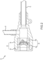
- cardiovascular introducer 18 includes an introducer sheath 12, a cannula unit 20, a hemostasis valve system 30, and a side-port fluid tubing 22 with an associated stopcock assembly 24.
- cannula unit 20 is comprised of a cap 28 and a housing 26 circumferentially sealed together, within which integral hemostasis valve system 30 (e.g., a fully assembled unit of two valve gaskets 30a and 30b as described herein), is disposed at its proximal end.
- Side-port fluid tubing 22 and associated stopcock assembly 24 are also coupled to cannula unit 20 or housing 26 to enable the introduction of medical fluids (e.g., saline) through introducer 18 or introducer sheath 12 for an intended clinical procedure.
- medical fluids e.g., saline
- FIG. 2 is a cross-sectional view of cardiovascular introducer 18 incorporating an integral hemostasis valve system 30 within a circumferentially sealed cannula unit 20.
- cannula unit 20 including housing 26 and cap 28, will be familiar to those of ordinary skill in the art; thus, cannula unit 20 will only be described herein to the extent necessary to understand the instant disclosure.
- first and second valve gaskets 30a, 30b collectively constitute a hemostasis valve system 30.
- first and second valve gaskets 30a, 30b are structurally identical to each other and are oriented back-to-back within housing 26. Accordingly, it should be understood that the descriptions of various valve gasket embodiments herein are equally applicable to either, or both, of valve gaskets 30a, 30b.
- valve gaskets 30a, 30b has two axial faces, one facing proximally and one facing distally.
- the first (e.g ., proximally-facing) axial face of a valve gasket will be referred to herein as the "entry face”
- the second (e.g., distally-facing) axial face of a valve gasket will be referred to herein as the "exit face.”
- This same naming convention will be utilized to refer to the various surfaces of the valve gasket embodiments described herein (that is, proximally-facing surfaces will be referred to as “entry faces,” while distally-facing surfaces will be referred to as “exit faces”).
- Figures 3A-3E are various views of a valve gasket 40 according to a first embodiment disclosed herein.
- the embodiment of Figures 3A-3E can be referred to as a "biomimetic bicuspid valve gasket” (or simply a "bicuspid valve gasket”).
- Figures 3A and 3B are perspective views of bicuspid valve gasket 40, with Figure 3A emphasizing the entry face of bicuspid valve gasket 40 and Figure 3B emphasizing the exit face of bicuspid valve gasket 40.
- Figure 3C is a planar view looking towards the entry face of bicuspid valve gasket 40.
- Figure 3D is a planar view looking towards the exit face of bicuspid valve gasket 40.
- Figure 3E is a cross-sectional view taken along line E-E in Figure 3C .
- Bicuspid valve gasket 40 includes an annular wall 42, a central protrusion 46, a plurality of ligaments 48, and a disc-shaped valve membrane 50.
- Ligaments 48 extend radially from central protrusion 46 to annular wall 42, and are attached to both.
- valve membrane 50 is attached to annular wall 42, central protrusion 46, and ligaments 48.
- bicuspid valve gasket 40 may be formed as a unitary assembly, such as by reactive injection molding, or reactive compression molding, with use of a liquid or gum-like silicone rubber material. And, although all elements may be integrally formed, the term "sealing assembly" will be used herein as a shorthand to refer collectively to valve membrane 50, central protrusion 46, and ligaments 48.
- Central protrusion 46 is centrally located within annular wall 42 and protrudes from the entry face of valve membrane 50. That is, central protrusion 46 is positioned on valve membrane 50 and has an axial centerline that is substantially coincident with the axial centerline of the annulus defined by annular wall 42. Central protrusion 46 may be cylindrical, hemispherical, or any other shape suitable to the interconnection of ligaments 48 as described below (e.g., a square-shaped central protrusion could be used in a four-ligament configuration).
- central protrusion 46 can include a guiding recess 52, which can be formed in the nature of a depression into the entry face of central protrusion 46.
- Guiding recess 52 may be conical, cylindrical, or any other suitable shape to help guide an interventional medical device towards the center of bicuspid valve gasket 40 during insertion.
- guiding recess 52 may have walls that slope conically inward, such that they are highest along the perimeter of guiding recess 52 and lowest near the center point of the annulus defined by annular wall 42.
- each ligament 48 is geometrically connected to both central protrusion 46 and annular wall 42 and extends generally along a radius of the annulus defined by annular wall 42 on the entry face of valve membrane 50 ( e.g., in the nature of a wheel spoke).
- Each ligament 48 extends above the entry face of membrane 50 to an upper surface 54.
- Upper surface 54 may be parallel or inclined to the entry face of valve membrane 50; where upper surface 54 is inclined relative to the entry face of valve membrane 50, it is contemplated that the highest point of upper surface 54 will be where it meets annular wall 42 and that the lowest point of upper surface 54 will be where it meets central protrusion 46 ( e.g., upper surface 54 of ligament 48 slopes downward towards central protrusion 46). This latter configuration is shown to good advantage in Figure 4E .
- valve membrane 50 is geometrically attached to annular wall 42, to central protrusion 46, and to each ligament 48. As explained in further detail below, these attachments support valve membrane 50, bias valve membrane 50 into a closed position ( e.g., to prevent fluid leakage through bicuspid valve gasket 40), permit resilient, radial compression, or opening, under insertion forces imposed on the entry face ( e.g., as an interventional medical device is inserted), and resist axial distension of valve membrane 50 under pressure (e.g ., blood pressure) imposed on the exit face.
- pressure e.g ., blood pressure
- At least one slit 56 is formed through valve membrane 50.
- slit 56 divides valve membrane 50, as well as central protrusion 46, into two substantially symmetrical flaps (also referred to as “segments,” “valve flaps,” or “leaflets”).
- Each ligament 48 likewise includes a slit therethrough.
- each ligament 48 includes a ligament slit 58 that divides the respective ligament into two relatively symmetrical ligament segments.
- each ligament slit 58 can be perpendicular to valve membrane 50.
- ligament slits 58 may be non-normal to valve membrane 50.
- any given ligament slit 58 can form an angle of between about 70 degrees and about 90 degrees, and, more desirably, an angle of between about 80 degrees and about 90 degrees, with valve membrane 50.
- ligament slits 58 are non-normal to valve membrane 50, it is contemplated that they will be generally centered on the entry face of ligaments 48.
- Ligaments 48 are arranged on valve membrane 50 such that their respective ligament slits 58 are planarly aligned with membrane slit(s) 56 (best illustrated in Figure 3E ). Indeed, ligament slits 58 can be formed at the same time as membrane slit(s) 56 by cutting through both valve membrane 50 and ligaments 48 at once.
- bicuspid valve gasket 40 includes two ligaments 48 positioned about 180 degrees from each other ( e.g., along slit 56).
- each of the two flaps of bicuspid valve gasket 40 is bounded along its outer circumferential edge by annular wall 42, along its inner circumferential edge by central protrusion 46, and on its radial edges by segments of ligaments 48.
- annular wall 42 includes a first, more proximal, generally cylindrical portion 42a and a second, more distal, beveled (or frustoconical) portion 42b.
- a plurality of positioning protrusions 60 extend in an axial direction from the exit face of generally cylindrical portion 42a.
- a plurality of positioning recesses 62 are set radially into a circumferential surface of beveled portion 42b, in between respective positioning protrusions 60 and beveled surfaces 64.
- positioning protrusions 60 alternate with positioning recesses 62 around the circumference of annular wall 42.
- each positioning recess 62 are geometrically complementary to the plurality of positioning protrusions 60.
- each positioning recess 62 can include a convex surface that is configured to mate with a corresponding concave surface on a respective positioning protrusion 60.
- the plurality of positioning recesses 62 are substantially aligned with membrane slit(s) 56.
- bicuspid valve gasket 40 includes two positioning protrusions 60 and two positioning recesses 62, alternately disposed around annular wall 42 at about 90-degree intervals. As described further below, this configuration helps ensure that a hemostasis valve system 20 including two bicuspid valve gaskets 40 arranged back-to-back will achieve a good seal.
- the same result could be achieved equally well with the plurality of positioning protrusions 60 aligned with the membrane slit(s) 56.
- Figures 4A-4E are various views of a valve gasket 70 according to a second embodiment disclosed herein.
- the embodiment of Figures 4A-4E can be referred to as a "biomimetic tricuspid valve gasket” (or simply a "tricuspid valve gasket”).
- Figures 4A and 4B are perspective views of tricuspid valve gasket 70, with Figure 4A emphasizing the entry face of tricuspid valve gasket 70 and Figure 4B emphasizing the exit face of tricuspid valve gasket 70.
- Figure 4C is a planar view looking towards the entry face of tricuspid valve gasket 70.
- Figure 4D is a planar view looking towards the exit face of tricuspid valve gasket 70.
- Figure 4E is a cross-sectional view taken along line E-E in Figure 4C .
- Tricuspid valve gasket 70 shares many structural features in common with bicuspid valve gasket 40.
- tricuspid valve gasket 70 includes an annular wall 42 (having both a generally cylindrical portion 42a and a beveled or frustoconical portion 42b), a central protrusion 46 with guiding recess 52, a plurality of ligaments 48, and a valve membrane 50.
- central protrusion 46 and valve membrane 50 include slits 56 therethrough, with ligaments 48 similarly including ligament slits 58.
- Tricuspid valve gasket 70 differs, however, in the number of ligaments 48, membrane slits 56, and ligament slits 58.
- tricuspid valve gasket 70 includes three ligaments 48 with corresponding ligament slits 58 and three slits 56 through membrane 50 and central protrusion 46.
- Ligaments 48 and slits 56 are disposed at about 120 degree intervals, thus dividing sealing assembly 44 of tricuspid valve gasket 70 into three substantially congruent flaps.
- each flap is bounded along its outer circumferential edge by annular wall 42, along its inner circumferential edge by central protrusion 46, and along its radial edges by segments of ligaments 48.
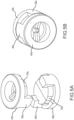
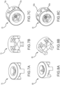
- Figures 5A and 5B illustrate a hemostasis valve system 20 as an assembly of two bicuspid valve gaskets 40a, 40b.
- Figures 6A and 6B illustrate a hemostasis valve system 20 as another assembly of two tricuspid valve gaskets 70a, 70b.
- the two valve gaskets 40a, 40b or 70a, 70b are positioned back-to-back (that is, exit face-to-exit face) such that the positioning protrusions 60a of the first gasket 40a, 70a mate into the positioning recesses 62b of the second gasket 40b, 70b, and vice versa, with tight interfacial contact between the respective valve membranes 50.
- valve membrane and ligament slits 56, 58 on each gasket 40a, 40b or 70a, 70b are aligned with the positioning recesses 62a, 62b, the slits 56, 58 on one valve gasket 40a, 70a will be rotationally offset from the slits 56, 58 on other valve gasket 40b, 70b when assembled together as shown and described.
- slits 56, 58 on one valve gasket 40a will be rotationally offset by about 90 degrees from slits 56, 58 on the other valve gasket 40b when the two are assembled together with tight interfacial contact between the exit faces of their respective valve membranes.
- slits 56, 58 on one valve gasket 70a will be rotationally offset by about 60 degrees from slits 56, 58 on the other valve gasket 70b when the two are assembled together with tight interfacial contact between the exit faces of their respective membranes.
- any gap that forms between a flap of one valve gasket 40a or 70a and an interventional medical device inserted therethrough will be misaligned with any gap that forms between a flap of the other valve gasket 40b or 70b and the same interventional medical device. This ensures that a hemostasis valve system 20 achieves a good seal and prevents fluid passage through both valve gaskets 40a, 40b or 70a, 70b.
- ligaments 48 will result in valve membranes 50 exhibiting a greater resistance to axial stretching than to radial or transverse compression when an interventional medical device is inserted or withdrawn through hemostasis valve system 20. This, in turn, will minimize axial deformation of the valve gaskets, and desirably reduce the potential for air embolism during the insertion and withdrawal of an interventional medical device.
- ligaments 48 will permit axial distension of the flaps. If, on the other hand, the interventional medical device is inserted through the exit face of the valve gasket, ligaments 48 will resist axial distension. Instead, both valve gaskets, as an integral hemostasis valve system 20, will be compressed radially, resulting in improved conformance to the outer profile of the interventional medical device and, in turn, a tighter seal against the interventional medical device.
- Suitable materials for valve gaskets as disclosed herein include various compliant and highly elastic polymeric materials, as well as polymeric foams with high resiliency. These include, without limitation, silicone rubber, urethane rubber, natural rubber (isoprene), and other synthetic hydrocarbon rubber materials (e.g ., ethylene-propylene-diene elastomer, styrenebutadiene rubber, neoprene rubber, nitrile or Buna-N rubber, butyl rubber, fluoroelastomers and the like).
- silicone rubber urethane rubber
- natural rubber isoprene
- other synthetic hydrocarbon rubber materials e.g ethylene-propylene-diene elastomer, styrenebutadiene rubber, neoprene rubber, nitrile or Buna-N rubber, butyl rubber, fluoroelastomers and the like.
- thermoplastic elastomers e.g ., styrenic, olefinic, polyester-based, and polyamide-based block copolymers and the like
- thermoplastic vulcanizates e.g ., thermoplastic polypropylene with vulcanized silicone rubber, thermoplastic polyurethane with vulcanized silicone rubber, and the like
- valve gasket with any number of flaps (or segments), including configurations that may not be biomimetic.
- Figures 7A-7C depict a valve gasket 75 that includes four substantially congruent flaps, and a hemostasis valve assembly 20 utilizing two such gaskets 75a, 75b
- Figures 8A-8C depict a valve gasket 80 that includes five substantially congruent flaps, and a hemostasis valve assembly 20 utilizing two such gaskets 80a, 80b.
- valve gaskets 75 and 80 share many structural features in common with bicuspid valve gasket 40 and tricuspid valve gasket 70, and differ primarily in the number of flaps and the number and placement of ligaments, slits, positioning protrusions, and positioning recesses.
- the flaps (or segments) need not be substantially equal in size, as results from regular spacing of the ligaments and slits around the central protrusion. Instead, the ligaments and slits can be positioned at irregular intervals around the central protrusion, yielding some flaps (or segments) that are larger than others.
- All directional references e.g ., upper, lower, upward, downward, left, right, leftward, rightward, top, bottom, above, below, vertical, horizontal, clockwise, and counterclockwise
- Joinder references e.g ., attached, coupled, connected, and the like
- Joinder references are to be construed broadly and may include intermediate members between a connection of elements and relative movement between elements. As such, joinder references do not necessarily infer that two elements are directly connected and in fixed relation to each other.
Landscapes
- Health & Medical Sciences (AREA)
- Heart & Thoracic Surgery (AREA)
- Pulmonology (AREA)
- Engineering & Computer Science (AREA)
- Anesthesiology (AREA)
- Biomedical Technology (AREA)
- Hematology (AREA)
- Life Sciences & Earth Sciences (AREA)
- Animal Behavior & Ethology (AREA)
- General Health & Medical Sciences (AREA)
- Public Health (AREA)
- Veterinary Medicine (AREA)
- Infusion, Injection, And Reservoir Apparatuses (AREA)
Claims (15)
- Eine Ventildichtung (30a, 30b, 40, 40a, 40b, 70, 70a, 70b, 80, 80a, 80b), die Folgendes umfasst:eine ringförmige Wand (42);eine Vielzahl von Bändern (48), die an der ringförmigen Wand (42) befestigt sind und sich radial einwärts von ihr erstrecken, wobei jedes Band (48) der Vielzahl von Bändern (48) einen Bandschlitz (58) einschließt, der das Band in zwei Bandsegmente aufteilt; undeine Membran (50), die von der ringförmigen Wand (42) umgeben ist und an der Vielzahl von Bändern (48) und an der ringförmigen Wand (42) befestigt ist, wobei die Membran (50) mindestens einen Membranschlitz (56) einschließt, der die Membran (50) in eine Vielzahl von Laschen aufteilt,wobei die Vielzahl von Bändern (48) so positioniert sind, dass die Vielzahl von Bandschlitzen (48) mit dem mindestens einen Membranschlitz (56) ausgerichtet ist, sodass jede Lasche an einem Umfangsrand entlang durch die ringförmige Wand (42), an einem ersten radialen Rand entlang durch ein erstes Bandsegment und an einem zweiten radialen Rand entlang durch ein zweites Bandsegment begrenzt wird.
- Ventildichtung (30a, 30b, 40, 40a, 40b, 70, 70a, 70b, 80, 80a, 80b) nach Anspruch 1, die ferner einen auf der Membran (50) positionierten zentralen Vorsprung (46) umfasst, wobei die Vielzahl von Bändern (48) mit dem zentralen Vorsprung (46) verbunden sind, wobei der zentrale Vorsprung bevorzugt eine Führungskerbe umfasst.
- Ventildichtung (30a, 30b, 40, 40a, 40b, 70, 70a, 70b, 80, 80a, 80b) nach Anspruch 1 oder 2, wobei die ringförmige Wand (42) Folgendes umfasst:einen zylinderförmigen Abschnitt (42a);einen abgeschrägten Abschnitt (42b);eine Vielzahl von Positionierungsvorsprüngen (60), die sich axial aus einer Austrittsfläche des zylinderförmigen Abschnitts (42a) erstrecken; undeine Vielzahl von Positionierungsaussparungen (62), die radial in einer Umfangsfläche des abgeschrägten Abschnitts (42b) eingesetzt sind.
- Ventildichtung (30a, 30b, 40, 40a, 40b, 70, 70a, 70b, 80, 80a, 80b) nach Anspruch 3, wobei die Vielzahl von Positionierungsaussparungen (62) komplementär zu der Vielzahl von Positionierungsvorsprüngen (60) sind.
- Ventildichtung (30a, 30b, 40, 40a, 40b, 70, 70a, 70b, 80, 80a, 80b) nach Anspruch 3, wobei die Vielzahl von Positionierungsaussparungen (62) mit dem mindestens einen Membranschlitz (56) ausgerichtet sind.
- Ventildichtung (30a, 30b, 40, 40a, 40b, 70, 70a, 70b, 80, 80a, 80b) nach Anspruch 3, wobei die Vielzahl von Positionierungsvorsprüngen (60) abwechselnd mit der Vielzahl von Positionierungsaussparungen (62) um einen Kreisumfang der ringförmigen Wand (42) angeordnet sind.
- Ventildichtung (30a, 30b, 40, 40a, 40b, 70, 70a, 70b, 80, 80a, 80b) nach einem der Ansprüche 1 bis 6, wobei der mindestens eine Membranschlitz (56) einen einzelnen Membranschlitz (56) umfasst, der die Membran (50) in zwei symmetrische Laschen aufteilt, oderwobei der mindestens eine Membranschlitz (56) drei Membranschlitze (56) umfasst, die die Membran (50) in drei deckungsgleiche Laschen aufteilen, oderwobei der Bandschlitz (58) jedes Bands einen Winkel zwischen 80 Grad und 90 Grad mit der Membran (50) bildet.
- Ein Hämostaseventil, das Folgendes umfasst:eine erste Ventildichtung (30a, 30b, 40, 40a, 40b, 70, 70a, 70b, 80, 80a, 80b) nach Anspruch 1 undeine zweite Ventildichtung (30a, 30b, 40, 40a, 40b, 70, 70a, 70b, 80, 80a, 80b) nach Anspruch 1,wobei eine Rückfläche der ersten Ventildichtung (30a, 30b, 40, 40a, 40b, 70, 70a, 70b, 80, 80a, 80b) gegen eine Rückfläche der zweiten Ventildichtung (30a, 30b, 40, 40a, 40b, 70, 70a, 70b, 80, 80a, 80b) platziert wird, wobei die Membran (50) der ersten Ventildichtung (30a, 30b, 40, 40a, 40b, 70, 70a, 70b, 80, 80a, 80b) gegen die Membran (50) der zweiten Ventildichtung (30a, 30b, 40, 40a, 40b, 70, 70a, 70b, 80, 80a, 80b) gedrückt wird.
- Hämostaseventil nach Anspruch 8, wobei:die erste Ventildichtung (30a, 30b, 40, 40a, 40b, 70, 70a, 70b, 80, 80a, 80b) ferner einen zentralen Vorsprung (46) umfasst, der auf der Membran (50) der ersten Ventildichtung positioniert ist, wobei die Vielzahl von Bändern (48) der ersten Ventildichtung mit dem zentralen Vorsprung (46) der ersten Ventildichtung verbunden sind; unddie zweite Ventildichtung (30a, 30b, 40, 40a, 40b, 70, 70a, 70b, 80, 80a, 80b) ferner einen zentralen Vorsprung (46) umfasst, der auf der Membran (50) der zweiten Ventildichtung positioniert ist, wobei die Vielzahl von Bändern (48) der zweiten Ventildichtung mit dem zentralen Vorsprung (46) der zweiten Ventildichtung verbunden sind, bevorzugtwobei mindestens einer von dem zentralen Vorsprung (46) der ersten Ventildichtung und dem zentralen Vorsprung (46) der zweiten Ventildichtung ferner eine Führungskerbe (52) umfasst.
- Hämostaseventil nach Anspruch 8, wobei:
die ringförmige Wand (42) der ersten Ventildichtung (30a, 30b, 40, 40a, 40b, 70, 70a, 70b, 80, 80a, 80b) Folgendes umfasst:einen zylinderförmigen Abschnitt (42a);einen abgeschrägten Abschnitt (42b);eine Vielzahl von Positionierungsvorsprüngen (60), die sich axial aus einer Austrittsfläche des zylinderförmigen Abschnitts (42a) erstrecken; undeine Vielzahl von Positionierungsaussparungen (62), die radial in eine Umfangsfläche des abgeschrägten Abschnitts (42b) eingesetzt sind;die ringförmige Wand (42) der zweiten Ventildichtung (30a, 30b, 40, 40a, 40b, 70, 70a, 70b, 80, 80a, 80b) Folgendes umfasst:einen zylinderförmigen Abschnitt (42a);einen abgeschrägten Abschnitt;eine Vielzahl von Positionierungsvorsprüngen (60), die sich axial aus einer Austrittsfläche des zylinderförmigen Abschnitts (42a) erstrecken; undeine Vielzahl von Positionierungsaussparungen (62), die radial in eine Umfangsfläche des abgeschrägten Abschnitts (42b) eingesetzt sind; unddie erste Ventildichtung gegen die zweite Ventildichtung platziert wird, sodass die Positionierungsvorsprünge (60) der ringförmigen Wand der ersten Ventildichtung in die Positionierungsaussparungen (62) der ringförmigen Wand der zweiten Ventildichtung hineinpassen und die Positionierungsvorsprünge (60) der ringförmigen Wand der zweiten Ventildichtung in die Positionierungsaussparungen (62) der ringförmigen Wand der ersten Ventildichtung hineinpassen. - Hämostaseventil nach Anspruch 10, wobei:a) die Positionierungsvorsprünge (60) der ringförmigen Wand (42) der ersten Ventildichtung komplementär zu den Positionierungsaussparungen (62) der ringförmigen Wand (42) der zweiten Ventildichtung sind, und
die Positionierungsvorsprünge (60) der ringförmigen Wand (42) der zweiten Ventildichtung komplementär zu den Positionierungsaussparungen (62) der ringförmigen Wand (42) der ersten Ventildichtung sind, oderb) die Positionierungsaussparungen (62) der ersten Ventildichtung mit dem mindestens einen Membranschlitz (56) der ersten Ventildichtung ausgerichtet sind, unddie Positionierungsaussparungen (62) der zweiten Ventildichtung mit dem mindestens einen Membranschlitz (56) der zweiten Ventildichtung ausgerichtet sind,sodass, wenn die Rückfläche der ersten Ventildichtung gegen die Rückfläche der zweiten Ventildichtung platziert wird, der mindestens eine Membranschlitz (56) der ersten Ventildichtung rotationsversetzt von dem mindestens einen Membranschlitz (56) der zweiten Ventildichtung ist. - Hämostaseventil nach einem der Ansprüche 8 bis 11, das ferner ein starres Ventilgehäuse umfasst und wobei die erste Ventildichtung und zweite Ventildichtung innerhalb des starren Ventilgehäuses angeordnet sind.
- Hämostaseventil nach einem der Ansprüche 8 bis 12, wobei die erste Ventildichtung strukturell identisch mit der zweiten Ventildichtung ist.
- Ventildichtung nach Anspruch 2, die Folgendes umfasst:
eine Dichtungsbaugruppe, die innerhalb der ringförmigen Wand angeordnet ist, wobei die Dichtungsbaugruppe Folgendes umfasst:den zentralen Vorsprung (46);die Vielzahl von Bändern (48), wobei sich jedes Band der Vielzahl von Bändern radial weg von dem zentralen Vorsprung zu der ringförmigen Wand hin erstreckt;die Membran (50); undmindestens einen Schlitz (56, 58) durch die Membran, den zentralen Vorsprung und die Vielzahl von Bändern, wobei der mindestens eine Schlitz die Dichtungsbaugruppe in eine Vielzahl von Ventillaschen trennt, wobei jede Ventillasche der Vielzahl von Ventillaschen an einem äußeren Umfangsrang durch die ringförmige Wand (42), an einem inneren Umfangsrand durch den zentralen Vorsprung (46), an einem ersten radialen Rand durch ein erstes Band (48) der Vielzahl von Bändern und an einem zweiten radialen Rand durch ein zweites Band (48) der Vielzahl von Bändern begrenzt wird. - Ventildichtung nach Anspruch 14, die ferner eine Vielzahl von beabstandeten Positionierungsvorsprüngen (60), die sich axial aus einem ersten Abschnitt der ringförmigen Wand erstrecken, und eine Vielzahl von Positionierungsaussparungen (62), die in eine Umfangsfläche eines zweiten Abschnitts der ringförmigen Wand eingesetzt sind, umfasst, wobei die Vielzahl von Positionierungsvorsprüngen (60) abwechselnd mit der Vielzahl von Positionierungsaussparungen (62) um einen Kreisumfang der ringförmigen Wand angeordnet sind.
Applications Claiming Priority (2)
| Application Number | Priority Date | Filing Date | Title |
|---|---|---|---|
| US202163191703P | 2021-05-21 | 2021-05-21 | |
| PCT/US2022/028566 WO2022245598A1 (en) | 2021-05-21 | 2022-05-10 | Valve gasket and hemostasis valves and cannula units incorporating the same |
Publications (2)
| Publication Number | Publication Date |
|---|---|
| EP4284486A1 EP4284486A1 (de) | 2023-12-06 |
| EP4284486B1 true EP4284486B1 (de) | 2025-04-30 |
Family
ID=82020236
Family Applications (1)
| Application Number | Title | Priority Date | Filing Date |
|---|---|---|---|
| EP22729861.9A Active EP4284486B1 (de) | 2021-05-21 | 2022-05-10 | Ventildichtung und hämostaseventile und kanüleneinheiten damit |
Country Status (3)
| Country | Link |
|---|---|
| US (1) | US20240252802A1 (de) |
| EP (1) | EP4284486B1 (de) |
| WO (1) | WO2022245598A1 (de) |
Families Citing this family (3)
| Publication number | Priority date | Publication date | Assignee | Title |
|---|---|---|---|---|
| WO2025128826A1 (en) | 2023-12-13 | 2025-06-19 | St. Jude Medical, Cardiology Division, Inc. | Flexible electrical components and medical devices incorporating the same |
| WO2025128753A1 (en) | 2023-12-15 | 2025-06-19 | St. Jude Medical, Cardiology Division, Inc. | Regulation of pressure differentials in interventional medical devices |
| WO2026043614A1 (en) | 2024-08-21 | 2026-02-26 | St. Jude Medical, Cardiology Division, Inc. | Vented medical device |
Family Cites Families (21)
| Publication number | Priority date | Publication date | Assignee | Title |
|---|---|---|---|---|
| US5269763A (en) * | 1991-07-18 | 1993-12-14 | Vernay Laboratories, Inc. | Self-sealing cannula cap |
| US5456284A (en) * | 1993-05-10 | 1995-10-10 | Applied Medical Resources Corporation | Elastomeric valve assembly |
| US5968068A (en) * | 1996-09-12 | 1999-10-19 | Baxter International Inc. | Endovascular delivery system |
| CA2327657A1 (en) * | 1998-03-10 | 1999-09-16 | Vernay Laboratories, Inc. | Hemostasis valve assembly including guide wire seal |
| US6024729A (en) * | 1998-03-10 | 2000-02-15 | Vernay Laboratories, Inc. | Hemostasis valve assembly including guide wire seal |
| US6551283B1 (en) * | 2000-01-25 | 2003-04-22 | St. Jude Medical, Daig Division | Hemostasis valve |
| US6632200B2 (en) * | 2000-01-25 | 2003-10-14 | St. Jude Medical, Daig Division | Hemostasis valve |
| US6699221B2 (en) * | 2000-06-15 | 2004-03-02 | Vincent L. Vaillancourt | Bloodless catheter |
| US7985232B2 (en) * | 2003-07-08 | 2011-07-26 | St. Jude Medical, Atrial Fibrillation Division, Inc. | Detachable hemostasis valve and splittable sheath assembly |
| US20090012476A1 (en) * | 2007-07-05 | 2009-01-08 | Galt Medical Corporation | Hemostasis valve for a catheter introducer |
| US8137321B2 (en) * | 2010-05-12 | 2012-03-20 | Medtronic Vascular, Inc. | Introducer sheath |
| EP2675722B1 (de) * | 2011-02-14 | 2017-05-17 | Becton, Dickinson and Company | Durchstechkappe |
| US9913972B2 (en) * | 2012-09-07 | 2018-03-13 | Intuitive Surgical Operations, Inc. | Cannula seal |
| US9114231B2 (en) * | 2013-03-15 | 2015-08-25 | B. Braun Melsungen Ag | Valved catheter assemblies and related methods |
| SG10201500101RA (en) * | 2014-01-08 | 2015-08-28 | Braun Melsungen Ag | Catheter assemblies with valves and related methods |
| SG10201503314VA (en) * | 2014-04-29 | 2015-11-27 | Braun Melsungen Ag | Valved catheter assemblies and related methods |
| EP3028737A1 (de) * | 2014-12-03 | 2016-06-08 | Tradinco AB | Selbstschließendes Katheterventil |
| CN108136160B (zh) * | 2015-08-18 | 2021-10-29 | B.布劳恩梅尔松根股份公司 | 带有阀的导管装置及相关方法 |
| WO2018132758A1 (en) * | 2017-01-12 | 2018-07-19 | I-V Access Technology, Inc. | Catheter valves |
| WO2020127328A1 (en) * | 2018-12-17 | 2020-06-25 | B. Braun Melsungen Ag | Over-the-needle catheter assemblies and related manufacturing method |
| CN112717269B (zh) * | 2021-01-07 | 2021-11-12 | 上海翰凌医疗器械有限公司 | 血管鞘装置、血管鞘装置与预扩张器的配合结构 |
-
2022
- 2022-05-10 WO PCT/US2022/028566 patent/WO2022245598A1/en not_active Ceased
- 2022-05-10 EP EP22729861.9A patent/EP4284486B1/de active Active
- 2022-05-10 US US18/560,978 patent/US20240252802A1/en active Pending
Also Published As
| Publication number | Publication date |
|---|---|
| WO2022245598A1 (en) | 2022-11-24 |
| US20240252802A1 (en) | 2024-08-01 |
| EP4284486A1 (de) | 2023-12-06 |
Similar Documents
| Publication | Publication Date | Title |
|---|---|---|
| US7081106B1 (en) | Hemostasis valve | |
| EP4284486B1 (de) | Ventildichtung und hämostaseventile und kanüleneinheiten damit | |
| CA2397432C (en) | Hemostasis valve | |
| AU2019201867B2 (en) | Transfer device valve | |
| EP0900105B1 (de) | Hämostatisches ventil | |
| US7101353B2 (en) | Splittable medical valve | |
| US7985232B2 (en) | Detachable hemostasis valve and splittable sheath assembly | |
| EP3207955B1 (de) | Austausch der kammer einer gefässzugangsvorrichtung | |
| RU2742869C2 (ru) | Внутривенный катетер с функцией безопасности и клапанным элементом, управляемым давлением | |
| US9168359B2 (en) | Modular introducer and exchange sheath | |
| CN107913444B (zh) | 导管组件 | |
| JPH0815495B2 (ja) | 止血套管ユニツト | |
| EP0442194A2 (de) | Zylindrischer Stopfen zum Abdichten eines Führungsdrahtes | |
| CN220110187U (zh) | 外周静脉内导管组件 |
Legal Events
| Date | Code | Title | Description |
|---|---|---|---|
| STAA | Information on the status of an ep patent application or granted ep patent |
Free format text: STATUS: UNKNOWN |
|
| STAA | Information on the status of an ep patent application or granted ep patent |
Free format text: STATUS: THE INTERNATIONAL PUBLICATION HAS BEEN MADE |
|
| PUAI | Public reference made under article 153(3) epc to a published international application that has entered the european phase |
Free format text: ORIGINAL CODE: 0009012 |
|
| STAA | Information on the status of an ep patent application or granted ep patent |
Free format text: STATUS: REQUEST FOR EXAMINATION WAS MADE |
|
| 17P | Request for examination filed |
Effective date: 20230831 |
|
| AK | Designated contracting states |
Kind code of ref document: A1 Designated state(s): AL AT BE BG CH CY CZ DE DK EE ES FI FR GB GR HR HU IE IS IT LI LT LU LV MC MK MT NL NO PL PT RO RS SE SI SK SM TR |
|
| GRAP | Despatch of communication of intention to grant a patent |
Free format text: ORIGINAL CODE: EPIDOSNIGR1 |
|
| STAA | Information on the status of an ep patent application or granted ep patent |
Free format text: STATUS: GRANT OF PATENT IS INTENDED |
|
| DAV | Request for validation of the european patent (deleted) | ||
| DAX | Request for extension of the european patent (deleted) | ||
| INTG | Intention to grant announced |
Effective date: 20240718 |
|
| GRAJ | Information related to disapproval of communication of intention to grant by the applicant or resumption of examination proceedings by the epo deleted |
Free format text: ORIGINAL CODE: EPIDOSDIGR1 |
|
| STAA | Information on the status of an ep patent application or granted ep patent |
Free format text: STATUS: REQUEST FOR EXAMINATION WAS MADE |
|
| GRAP | Despatch of communication of intention to grant a patent |
Free format text: ORIGINAL CODE: EPIDOSNIGR1 |
|
| STAA | Information on the status of an ep patent application or granted ep patent |
Free format text: STATUS: GRANT OF PATENT IS INTENDED |
|
| INTC | Intention to grant announced (deleted) | ||
| INTG | Intention to grant announced |
Effective date: 20241125 |
|
| GRAS | Grant fee paid |
Free format text: ORIGINAL CODE: EPIDOSNIGR3 |
|
| GRAA | (expected) grant |
Free format text: ORIGINAL CODE: 0009210 |
|
| STAA | Information on the status of an ep patent application or granted ep patent |
Free format text: STATUS: THE PATENT HAS BEEN GRANTED |
|
| AK | Designated contracting states |
Kind code of ref document: B1 Designated state(s): AL AT BE BG CH CY CZ DE DK EE ES FI FR GB GR HR HU IE IS IT LI LT LU LV MC MK MT NL NO PL PT RO RS SE SI SK SM TR |
|
| P01 | Opt-out of the competence of the unified patent court (upc) registered |
Free format text: CASE NUMBER: APP_14024/2025 Effective date: 20250321 |
|
| REG | Reference to a national code |
Ref country code: CH Ref legal event code: EP Ref country code: GB Ref legal event code: FG4D |
|
| REG | Reference to a national code |
Ref country code: IE Ref legal event code: FG4D |
|
| REG | Reference to a national code |
Ref country code: DE Ref legal event code: R096 Ref document number: 602022013937 Country of ref document: DE |
|
| PGFP | Annual fee paid to national office [announced via postgrant information from national office to epo] |
Ref country code: DE Payment date: 20250527 Year of fee payment: 4 |
|
| PGFP | Annual fee paid to national office [announced via postgrant information from national office to epo] |
Ref country code: IT Payment date: 20250531 Year of fee payment: 4 |
|
| PGFP | Annual fee paid to national office [announced via postgrant information from national office to epo] |
Ref country code: FR Payment date: 20250521 Year of fee payment: 4 |
|
| PGFP | Annual fee paid to national office [announced via postgrant information from national office to epo] |
Ref country code: AT Payment date: 20250721 Year of fee payment: 4 |
|
| REG | Reference to a national code |
Ref country code: NL Ref legal event code: MP Effective date: 20250430 |
|
| REG | Reference to a national code |
Ref country code: AT Ref legal event code: MK05 Ref document number: 1789488 Country of ref document: AT Kind code of ref document: T Effective date: 20250430 |
|
| PG25 | Lapsed in a contracting state [announced via postgrant information from national office to epo] |
Ref country code: PT Free format text: LAPSE BECAUSE OF FAILURE TO SUBMIT A TRANSLATION OF THE DESCRIPTION OR TO PAY THE FEE WITHIN THE PRESCRIBED TIME-LIMIT Effective date: 20250901 Ref country code: ES Free format text: LAPSE BECAUSE OF FAILURE TO SUBMIT A TRANSLATION OF THE DESCRIPTION OR TO PAY THE FEE WITHIN THE PRESCRIBED TIME-LIMIT Effective date: 20250430 Ref country code: FI Free format text: LAPSE BECAUSE OF FAILURE TO SUBMIT A TRANSLATION OF THE DESCRIPTION OR TO PAY THE FEE WITHIN THE PRESCRIBED TIME-LIMIT Effective date: 20250430 |
|
| REG | Reference to a national code |
Ref country code: LT Ref legal event code: MG9D |
|
| PG25 | Lapsed in a contracting state [announced via postgrant information from national office to epo] |
Ref country code: NO Free format text: LAPSE BECAUSE OF FAILURE TO SUBMIT A TRANSLATION OF THE DESCRIPTION OR TO PAY THE FEE WITHIN THE PRESCRIBED TIME-LIMIT Effective date: 20250730 Ref country code: GR Free format text: LAPSE BECAUSE OF FAILURE TO SUBMIT A TRANSLATION OF THE DESCRIPTION OR TO PAY THE FEE WITHIN THE PRESCRIBED TIME-LIMIT Effective date: 20250731 |
|
| PG25 | Lapsed in a contracting state [announced via postgrant information from national office to epo] |
Ref country code: NL Free format text: LAPSE BECAUSE OF FAILURE TO SUBMIT A TRANSLATION OF THE DESCRIPTION OR TO PAY THE FEE WITHIN THE PRESCRIBED TIME-LIMIT Effective date: 20250430 Ref country code: PL Free format text: LAPSE BECAUSE OF FAILURE TO SUBMIT A TRANSLATION OF THE DESCRIPTION OR TO PAY THE FEE WITHIN THE PRESCRIBED TIME-LIMIT Effective date: 20250430 |
|
| PG25 | Lapsed in a contracting state [announced via postgrant information from national office to epo] |
Ref country code: BG Free format text: LAPSE BECAUSE OF FAILURE TO SUBMIT A TRANSLATION OF THE DESCRIPTION OR TO PAY THE FEE WITHIN THE PRESCRIBED TIME-LIMIT Effective date: 20250430 |
|
| PG25 | Lapsed in a contracting state [announced via postgrant information from national office to epo] |
Ref country code: HR Free format text: LAPSE BECAUSE OF FAILURE TO SUBMIT A TRANSLATION OF THE DESCRIPTION OR TO PAY THE FEE WITHIN THE PRESCRIBED TIME-LIMIT Effective date: 20250430 Ref country code: AT Free format text: LAPSE BECAUSE OF FAILURE TO SUBMIT A TRANSLATION OF THE DESCRIPTION OR TO PAY THE FEE WITHIN THE PRESCRIBED TIME-LIMIT Effective date: 20250430 |
|
| PG25 | Lapsed in a contracting state [announced via postgrant information from national office to epo] |
Ref country code: RS Free format text: LAPSE BECAUSE OF FAILURE TO SUBMIT A TRANSLATION OF THE DESCRIPTION OR TO PAY THE FEE WITHIN THE PRESCRIBED TIME-LIMIT Effective date: 20250731 |
|
| PG25 | Lapsed in a contracting state [announced via postgrant information from national office to epo] |
Ref country code: IS Free format text: LAPSE BECAUSE OF FAILURE TO SUBMIT A TRANSLATION OF THE DESCRIPTION OR TO PAY THE FEE WITHIN THE PRESCRIBED TIME-LIMIT Effective date: 20250830 |
|
| PG25 | Lapsed in a contracting state [announced via postgrant information from national office to epo] |
Ref country code: LV Free format text: LAPSE BECAUSE OF FAILURE TO SUBMIT A TRANSLATION OF THE DESCRIPTION OR TO PAY THE FEE WITHIN THE PRESCRIBED TIME-LIMIT Effective date: 20250430 |
|
| REG | Reference to a national code |
Ref country code: CH Ref legal event code: H13 Free format text: ST27 STATUS EVENT CODE: U-0-0-H10-H13 (AS PROVIDED BY THE NATIONAL OFFICE) Effective date: 20251223 |
|
| PG25 | Lapsed in a contracting state [announced via postgrant information from national office to epo] |
Ref country code: SM Free format text: LAPSE BECAUSE OF FAILURE TO SUBMIT A TRANSLATION OF THE DESCRIPTION OR TO PAY THE FEE WITHIN THE PRESCRIBED TIME-LIMIT Effective date: 20250430 Ref country code: DK Free format text: LAPSE BECAUSE OF FAILURE TO SUBMIT A TRANSLATION OF THE DESCRIPTION OR TO PAY THE FEE WITHIN THE PRESCRIBED TIME-LIMIT Effective date: 20250430 |
|
| PG25 | Lapsed in a contracting state [announced via postgrant information from national office to epo] |
Ref country code: LU Free format text: LAPSE BECAUSE OF NON-PAYMENT OF DUE FEES Effective date: 20250510 |
|
| PG25 | Lapsed in a contracting state [announced via postgrant information from national office to epo] |
Ref country code: CH Free format text: LAPSE BECAUSE OF NON-PAYMENT OF DUE FEES Effective date: 20250531 |
|
| PG25 | Lapsed in a contracting state [announced via postgrant information from national office to epo] |
Ref country code: CZ Free format text: LAPSE BECAUSE OF FAILURE TO SUBMIT A TRANSLATION OF THE DESCRIPTION OR TO PAY THE FEE WITHIN THE PRESCRIBED TIME-LIMIT Effective date: 20250430 |
|
| PG25 | Lapsed in a contracting state [announced via postgrant information from national office to epo] |
Ref country code: EE Free format text: LAPSE BECAUSE OF FAILURE TO SUBMIT A TRANSLATION OF THE DESCRIPTION OR TO PAY THE FEE WITHIN THE PRESCRIBED TIME-LIMIT Effective date: 20250430 |
|
| PG25 | Lapsed in a contracting state [announced via postgrant information from national office to epo] |
Ref country code: SK Free format text: LAPSE BECAUSE OF FAILURE TO SUBMIT A TRANSLATION OF THE DESCRIPTION OR TO PAY THE FEE WITHIN THE PRESCRIBED TIME-LIMIT Effective date: 20250430 |
|
| REG | Reference to a national code |
Ref country code: BE Ref legal event code: MM Effective date: 20250531 |
|
| PG25 | Lapsed in a contracting state [announced via postgrant information from national office to epo] |
Ref country code: MC Free format text: LAPSE BECAUSE OF FAILURE TO SUBMIT A TRANSLATION OF THE DESCRIPTION OR TO PAY THE FEE WITHIN THE PRESCRIBED TIME-LIMIT Effective date: 20250430 |
|
| REG | Reference to a national code |
Ref country code: DE Ref legal event code: R097 Ref document number: 602022013937 Country of ref document: DE |
|
| PG25 | Lapsed in a contracting state [announced via postgrant information from national office to epo] |
Ref country code: RO Free format text: LAPSE BECAUSE OF FAILURE TO SUBMIT A TRANSLATION OF THE DESCRIPTION OR TO PAY THE FEE WITHIN THE PRESCRIBED TIME-LIMIT Effective date: 20250430 |
|
| PLBE | No opposition filed within time limit |
Free format text: ORIGINAL CODE: 0009261 |
|
| STAA | Information on the status of an ep patent application or granted ep patent |
Free format text: STATUS: NO OPPOSITION FILED WITHIN TIME LIMIT |
|
| REG | Reference to a national code |
Ref country code: CH Ref legal event code: L10 Free format text: ST27 STATUS EVENT CODE: U-0-0-L10-L00 (AS PROVIDED BY THE NATIONAL OFFICE) Effective date: 20260311 |