EP4283637A1 - Fader device - Google Patents
Fader device Download PDFInfo
- Publication number
- EP4283637A1 EP4283637A1 EP21921146.3A EP21921146A EP4283637A1 EP 4283637 A1 EP4283637 A1 EP 4283637A1 EP 21921146 A EP21921146 A EP 21921146A EP 4283637 A1 EP4283637 A1 EP 4283637A1
- Authority
- EP
- European Patent Office
- Prior art keywords
- screw shaft
- moving body
- cover member
- shafts
- fader device
- Prior art date
- Legal status (The legal status is an assumption and is not a legal conclusion. Google has not performed a legal analysis and makes no representation as to the accuracy of the status listed.)
- Withdrawn
Links
Images



Classifications
-
- H—ELECTRICITY
- H01—ELECTRIC ELEMENTS
- H01C—RESISTORS
- H01C10/00—Adjustable resistors
- H01C10/30—Adjustable resistors the contact sliding along resistive element
- H01C10/38—Adjustable resistors the contact sliding along resistive element the contact moving along a straight path
-
- H—ELECTRICITY
- H01—ELECTRIC ELEMENTS
- H01C—RESISTORS
- H01C10/00—Adjustable resistors
- H01C10/30—Adjustable resistors the contact sliding along resistive element
- H01C10/38—Adjustable resistors the contact sliding along resistive element the contact moving along a straight path
- H01C10/40—Adjustable resistors the contact sliding along resistive element the contact moving along a straight path screw operated
-
- F—MECHANICAL ENGINEERING; LIGHTING; HEATING; WEAPONS; BLASTING
- F16—ENGINEERING ELEMENTS AND UNITS; GENERAL MEASURES FOR PRODUCING AND MAINTAINING EFFECTIVE FUNCTIONING OF MACHINES OR INSTALLATIONS; THERMAL INSULATION IN GENERAL
- F16H—GEARING
- F16H25/00—Gearings comprising primarily only cams, cam-followers and screw-and-nut mechanisms
- F16H25/18—Gearings comprising primarily only cams, cam-followers and screw-and-nut mechanisms for conveying or interconverting oscillating or reciprocating motions
- F16H25/20—Screw mechanisms
-
- H—ELECTRICITY
- H01—ELECTRIC ELEMENTS
- H01C—RESISTORS
- H01C10/00—Adjustable resistors
- H01C10/30—Adjustable resistors the contact sliding along resistive element
- H01C10/38—Adjustable resistors the contact sliding along resistive element the contact moving along a straight path
- H01C10/40—Adjustable resistors the contact sliding along resistive element the contact moving along a straight path screw operated
- H01C10/42—Adjustable resistors the contact sliding along resistive element the contact moving along a straight path screw operated the contact bridging and sliding along resistive element and parallel conducting bar or collector
-
- F—MECHANICAL ENGINEERING; LIGHTING; HEATING; WEAPONS; BLASTING
- F16—ENGINEERING ELEMENTS AND UNITS; GENERAL MEASURES FOR PRODUCING AND MAINTAINING EFFECTIVE FUNCTIONING OF MACHINES OR INSTALLATIONS; THERMAL INSULATION IN GENERAL
- F16H—GEARING
- F16H25/00—Gearings comprising primarily only cams, cam-followers and screw-and-nut mechanisms
- F16H25/18—Gearings comprising primarily only cams, cam-followers and screw-and-nut mechanisms for conveying or interconverting oscillating or reciprocating motions
- F16H25/20—Screw mechanisms
- F16H2025/2031—Actuator casings
-
- F—MECHANICAL ENGINEERING; LIGHTING; HEATING; WEAPONS; BLASTING
- F16—ENGINEERING ELEMENTS AND UNITS; GENERAL MEASURES FOR PRODUCING AND MAINTAINING EFFECTIVE FUNCTIONING OF MACHINES OR INSTALLATIONS; THERMAL INSULATION IN GENERAL
- F16H—GEARING
- F16H25/00—Gearings comprising primarily only cams, cam-followers and screw-and-nut mechanisms
- F16H25/18—Gearings comprising primarily only cams, cam-followers and screw-and-nut mechanisms for conveying or interconverting oscillating or reciprocating motions
- F16H25/20—Screw mechanisms
- F16H2025/204—Axial sliding means, i.e. for rotary support and axial guiding of nut or screw shaft
Definitions
- the present invention relates to a fader device.
- Patent Document 1 discloses a fader device having a moving body that can move in a linear direction.
- a fader device adjusts various parameter values (for example, volume of sound collected by a microphone, illuminance of lighting, and the like) by moving a moving body.
- a moving body is attached to a portion of an endless belt wound around a plurality of pulleys in the circumferential direction.
- Patent Document 1 Japanese Unexamined Patent Application, First Publication No. H09-171910
- the moving body in this type of fader device, it is conceivable for the moving body to be moved by the driving force of a motor in response to a control signal input from the outside.
- a single pulley may be rotationally driven by the driving force of a motor.
- the moving body can be moved by transmitting the driving force of the motor to the moving body via the pulley and the endless belt.
- the tension (tensile force) applied to the endless belt should be large.
- the tension acting on the endless belt is large, the resistance when manually moving the moving body increases, making it difficult to move the moving body finely and thus impairing the operational feeling of the moving body.
- the tension applied to the endless belt is reduced in order to facilitate manual movement of the moving body, the pulley rotationally driven by the motor tends to slip relative to the endless belt, or the teeth tend to skip. For this reason, it becomes difficult to move the moving body with high precision by the motor.
- the present invention has been achieved in view of the above circumstances and an object thereof is to provide a fader device capable of accurately moving a moving body by means of a motor while improving the operational feeling of the moving body.
- a first aspect of the present invention is a fader device including: a plurality of shafts that are parallel to each other; and a moving body that is attached to the plurality of shafts so as to be capable of moving in a longitudinal direction of the plurality of shafts, wherein at least one of the plurality of shafts is a screw shaft having a male thread on an outer periphery thereof and being configured to be rotatable about an axis extending along the longitudinal direction, the other shaft that is the plurality of shafts other than the screw shaft is a guide shaft that guides the moving body in the longitudinal direction, and the moving body, by meshing with the male thread, moves in the longitudinal direction as the screw shaft rotates.
- a second aspect of the present invention is a fader device including: a screw shaft extending in a linear direction, having a thread, and being rotatable about an axis extending in the linear direction; a guide member extending in the linear direction so as to be parallel to the screw shaft; and a moving body attached to the screw shaft and the guide member so to be movable in the linear direction; wherein the moving body, by meshing with the thread, moves in the linear direction as the screw shaft rotates.
- a third aspect of the present invention is a fader device including: a screw shaft extending in a linear direction, having a male thread on an outer periphery thereof, and being rotatable about an axis extending in the linear direction; a moving body that is attached to the screw shaft and, by meshing with the male thread, moves in the linear direction as the screw shaft rotates; a partition member that separates a first region where the screw shaft is located from a second region that is different from the first region, the partition member having an insertion hole that extends in the linear direction and through which the moving body is inserted from a side of the first region to a side of the second region; and a cover member positioned between the screw shaft and the insertion hole of the partition member in the first region and extending in the linear direction.
- a moving body can be precisely moved by a motor or other means while improving the operational feeling of the moving body.
- FIGS. 1 to 3 A first embodiment of the present invention will be described below with reference to FIGS. 1 to 3 .
- a fader device 1 As shown in FIG. 1 , a fader device 1 according to the first embodiment includes a plurality of shafts 2 and a moving body3. The fader device 1 also includes a base 4.
- the plurality of shafts 2 are each formed in a rod shape extending in a straight line direction.
- the plurality of shafts 2 are arranged parallel to each other. Further, the plurality of shafts 2 are spaced apart from each other when viewed in the longitudinal direction of the shafts 2 (see FIG. 2 ). In the present embodiment, the plurality of shafts 2 are arranged spaced apart in a row in a direction perpendicular to the longitudinal direction of the shafts 2.
- the base 4 has a pair of support portions 41 spaced apart in the longitudinal direction of the shafts 2. Both end portions of the shafts 2 in the longitudinal direction are inserted or passed through the pair of support portions 41. The plurality of shafts 2 are thereby supported by the base 4.
- the base 4 including the pair of support portions 41 may be configured by, for example, a housing (case) that accommodates the plurality of shafts 2 and a main body portion 31 of the moving body 3 to be described later.
- the number of shafts 2 in the present embodiment is two.
- the screw shaft 21 has a male thread 211 on the outer circumference thereof.
- the male thread 211 may be a single thread or a multi-threaded thread.
- the screw shaft 21 is rotatable around an axis A 1 extending in the longitudinal direction of the shafts 2.
- the pair of support portions 41 that support both end portions in the longitudinal direction of the screw shaft 21 function as bearings that rotatably support the screw shaft 21,
- the other one of the two shafts 2 is a guide shaft 22 (guide member).
- the guide shaft 22 is configured to guide the moving body 3, to be described later, in the longitudinal direction of the shafts 2.
- the guide shaft 22 also serves to prevent the moving body3 from rattling with respect to the screw shaft 21 and the base 4 in the direction orthogonal to the longitudinal direction of the shafts 2.
- the guide shaft 22 is formed in a rod-like shape with no irregularities such as the male thread 211 on the outer circumference thereof.
- the guide shaft 22 may be formed in, for example, a polygonal prismatic shape, but is formed in a columnar shape in this embodiment.
- the diameter D2 of the guide shaft 22 is larger than the diameter D1 of the screw shaft 21.
- the diameter D2 of the guide shaft 22 may be substantially equal to the diameter D1 of the screw shaft 21, for example.
- the moving body3 is attached to the plurality of shafts 2 so as to be movable in the longitudinal direction of the shafts 2 with respect to the plurality of shafts 2.
- the moving body 3 of the present embodiment has a main body portion 31 and an operation portion 32 extending from the main body portion 31.
- the main body portion 31 is formed with a plurality of through holes 33 and 34 through which the plurality of shafts 2 are individually inserted.
- the number of through holes 33, 34 corresponds to the number of shafts 2.
- the plurality of through holes 33, 34 are parallel to each other. As a result, the moving body3 can move in the longitudinal direction with respect to the plurality of shafts 2.
- the plurality of through holes 33 and 34 include a first through hole 33 through which the screw shaft 21 is inserted and a second through hole 34 through which the guide shaft 22 is inserted.
- the moving body 3 is configured to mesh with the male thread 211 of the screw shaft 21 so as to move in the longitudinal direction of the shafts 2 as the screw shaft 21 rotates, by meshing with the male thread 211 of the screw shaft 21.
- the moving body 3 has an engaging portion 35 that engages the male thread 211 of the screw shaft 21.
- the engaging portion 35 is provided on the inner periphery of the first through hole 33 of the moving body 3 through which the screw shaft 21 is inserted.
- the engaging portion 35 of this embodiment is a female thread 351 formed on the inner circumference of the first through hole 33 of the moving body 3.
- Female thread 351 may be a single thread or a multiple-threaded thread corresponding to male thread 211.
- the female thread 351 of the main body 31 meshes with the male thread 211 of the screw shaft 21, so that the moving body 3 can move in the longitudinal direction of the shafts 2 (horizontal direction in FIG. 3 ) as the screw shaft 21 rotates.
- the moving body 3 is also supported by the guide shaft 22 separate from the screw shaft 21, so that even if the screw shaft 21 rotates, the moving body 3 is prevented from rotating with the screw shaft 21 around the axis A1.
- the operation portion 32 of the moving body 3 is a part that the operator touches with fingers to move the moving body 3 manually.
- the operating portion 32 extends in a direction perpendicular to the longitudinal direction of the shafts 2 with respect to the main body portion 31.
- the operating portion 32, the screw shaft 21, and the guide shaft 22 are arranged in a row in a direction orthogonal to the longitudinal direction of the shafts 2 (vertical direction in FIG. 2 ).
- the fader device I of the present embodiment further includes a position measuring unit 5 that measures the position of the moving body 3 in the longitudinal direction of the shaft 2.
- the position measuring unit 5 of the present embodiment includes an encoder 51.
- a shaft (not shown) of the encoder 51 is coupled to the screw shaft 21.
- the encoder 51 measures the rotation angle of the screw shaft 21.
- the position measuring unit 5 further includes a position calculation unit 52.
- the position calculation unit 52 calculates the position of the moving body 3 in the longitudinal direction of the shafts 2 based on the rotation angle of the screw shaft 21 measured by the encoder 51. Thereby, the position of the moving body 3 in the longitudinal direction of the shafts 2 can be measured.
- the fader device 1 of the present embodiment further includes a motor 6 that rotationally drives the screw shaft 21.
- a drive shaft (not shown) of the motor 6 is coupled to the screw shaft 21.
- the motor 6 may be, for example, a stepping motor capable of positioning the moving body 3 with high accuracy.
- the motor 6 is arranged between the screw shaft 21 and the encoder 51. For this reason, the shaft of the encoder 51 is coupled to the screw shaft 21 via the drive shaft of the motor 6.
- the moving body 3 can be moved in the longitudinal direction of the shafts 2 by rotationally driving the screw shaft 21 with the driving force of the motor 6.
- the screw shaft 21 rotates.
- the structure in which the screw shaft 21 rotates with the movement of the moving body 3 can reduce the resistance when the operator moves the moving body 3 manually (resistance to the movement of the moving body 3), compared to the conventional structure in which an endless belt wound around a plurality of pulleys moves as the moving body 3 moves. Thereby, the operational feeling of the moving body 3 can be improved.
- the moving body 3 meshes with the male thread 211 of the screw shaft 21. For that reason, the moving body 3 does not slip on the screw shaft 21 and there is no skipping of teeth. That is, it becomes possible to move the moving body 3 with high accuracy by the motor 6.
- the fader device 1 of the present embodiment eliminates the need for strict adjustment of tension in the conventional structure that utilizes an endless belt. Therefore, it is possible to reduce the number of man-hours for manufacturing the fader device 1 and to keep manufacturing costs low.
- the diameter D1 of the screw shaft 21 is smaller than the diameter D2 of the guide shaft 22. Since the screw shaft 21 is thin, the friction generated between the screw shaft 21 and the moving body 3 can be kept small. As a result, the resistance when the operator manually moves the moving body 3 can be further reduced, and the operational feeling of the moving body 3 can be further improved.
- the fader device 1 of the present embodiment also has only two shafts 2 attached to the moving body 3. By attaching the moving body 3 to these two shafts 2, the orientation of the moving body 3 can be maintained so that the moving body 3 does not rotate around the shafts 2.
- One of the two shafts 2 is a screw shaft 21 for moving the moving body in the longitudinal direction of the shafts 2. Therefore, compared with the conventional structure using an endless belt, there is no need to separately provide a component for moving the moving body 3 by the motor 6, and so the number of constituent parts of the fader device 1 can be reduced.
- the position measuring unit 5 that measures the position of the moving body 3 in the longitudinal direction of the shaft 2 has an encoder 51 that measures the rotation angle of the screw shaft 21. Therefore, the length of travel of the moving body 3 in the longitudinal direction of the shafts 2 can be calculated based on the rotation angle of the screw shaft 21 measured by the encoder 51. Therefore, the position of the moving body 3 can be measured.
- the position of the moving body 3 can be measured by the position measuring unit 5 with high accuracy.
- the encoder 51 used as the position measuring unit 5 can reduce the number of parts constituting the position measuring unit 5 and achieve space savings of the position measuring unit 5 compared to a structure that directly measures the position of the moving body 3 that linearly moves. As a result, the size of the fader device 1 can be easily reduced.
- the operation portion 32, the screw shaft 21, and the guide shaft 22 are arranged in a row in a direction perpendicular to the longitudinal direction of the shafts 2 (vertical direction in FIG. 2 ), but it is not limited thereto.
- the direction in which the screw shaft 21 and the guide shaft 22 are aligned may be orthogonal (left-right direction in FIG. 2 ) to the direction in which the operation portion 32 and the shaft 2 (screw shaft 21 or guide shaft 22) are aligned (vertical in FIG. 2 ).
- the operation portion 32, screw shaft 21, and guide shaft 22 arranged in a row in the vertical direction, as illustrated in FIG. 2 .
- FIGS. 4 and 5 a second embodiment of the present invention will be described with reference to FIGS. 4 and 5 .
- the same reference numerals are given to the same configurations as those already described, and redundant descriptions will be omitted.
- a fader device 1E includes a plurality of shafts 2, a moving body3, and a base 4, as in the first embodiment.
- the plurality of shafts 2 include a screw shaft 21 and guide shafts 22 similar to those in the first embodiment.
- the fader device 1E of the second embodiment has a plurality of guide shafts 22.
- the plurality of guide shafts 22 are arranged so as to surround the screw shaft 21 when viewed from the longitudinal direction of the shafts 2.
- the plurality of guide shafts 22 may be arranged at regular intervals in the circumferential direction around the screw shaft 21 when viewed from the longitudinal direction of the shafts 2.
- the number of guide shafts 22 in the second embodiment is two.
- the two guide shafts 22 are equally spaced (180 degrees apart) in the circumferential direction around the screw shaft 21 when viewed from the longitudinal direction of the shafts 2. Therefore, the screw shaft 21 is positioned between the two guide shafts 22 when viewed in the longitudinal direction of the shafts 2. That is, the screw shaft 21 and the two guide shafts 22 are arranged in a row in a direction orthogonal to the longitudinal direction of the shafts 2.
- the operation portion 32, the screw shaft 21, and the two guide shafts 22 are arranged in a row in the direction perpendicular to the longitudinal direction of the shafts 2 (vertical direction in FIG. 5 ). As a result, the width dimension of the fader device 1E in the left-right direction in FIG. 5 can be kept small.
- the plurality of guide shafts 22 are arranged so as to surround the screw shaft 21 when viewed from the longitudinal direction of the shafts 2. Therefore, the load when the operator manually moves the moving body 3 is more likely to act on the multiple guide shafts 22. As a result, the load acting on the screw shaft 21 can be reduced. Therefore, it is possible to form the screw shaft 21 thinner. Thereby, the friction generated between the screw shaft 21 and the moving body 3 can be further suppressed. Accordingly, the resistance when moving the moving body 3 manually can be further reduced, and the operational feeling of the moving body 3 can be further improved.
- the number of the guide shafts 22 may be three or more.
- three or more guide shafts 22 may be arranged at regular intervals in the circumferential direction around the screw shaft 21 when viewed from the longitudinal direction of the shafts 2, as illustrated in FIG. 6 .
- the width dimension of the fader device 1 in the horizontal direction tends to increase.
- three or more guide shafts 22 may be arranged at uneven intervals in the circumferential direction around the screw shaft 21 so that the width dimension of the fader device 1 is reduced, for example.
- the guide shaft 22 is not limited to being inserted through the second through hole 34 of the moving body 3, and for example may be provided to support the moving body 3 (main body portion 31) from the outside thereof.
- the position measuring unit 5 that measures the position of the moving body 3 is not limited to the configuration that measures the position of the moving body 3 based on the rotational position of the screw shaft 21, but may also be configured to directly measure the position of the moving body 3, for example.
- FIGS. 7 to 12 a third embodiment of the present invention will be described with reference to FIGS. 7 to 12 .
- the same reference numerals are given to the same configurations as those already described, and redundant descriptions will be omitted.
- a fader device 1F includes a screw shaft 21, a moving body 3F, a partition member 7F, and a cover member 8F. Further, the fader device 1F further includes a pair of support portions 41F and a motor 6.
- the screw shaft 21 shown in FIGS. 8 to 10 is formed in a rod shape extending in a straight line and has a male thread 211 on the outer circumference thereof, as in the first and second embodiments. Both end portions of the screw shaft 21 in the longitudinal direction are supported by the pair of support portions 41F so that the screw shaft 21 can rotate about the axis A1.
- the motor 6 rotationally drives the screw shaft 21 as in the first and second embodiments.
- the motor 6 is attached to one support portion 41F.
- the moving body 3F is attached to the screw shaft 21 as in the first and second embodiments. Further, the moving body 3F is configured to mesh with the male thread 211 of the screw shaft 21 so as to move in the longitudinal direction (linear direction) of the screw shaft 21 as the screw shaft 21 rotates. Although not shown, the aspect of the moving body 3F that engages with the male thread 211 of the screw shaft 21 may be the same as that of the first embodiment (for example, the engaging portion 35 illustrated in FIG. 3 ).
- the partition member 7F forms a partition into a first region R1 where the screw shaft 21 is arranged and a second region R2 different from the first region R1.
- the partition member 7F has an insertion hole 71F through which a portion of the moving body 3F attached to the screw shaft 21 is inserted from the first region R1 side to the second region R2 side.
- the insertion hole 71F extends in the longitudinal direction of the screw shaft 21 (that is, the moving direction of the moving body 3F).
- the partition member 7F of the present embodiment is a panel member formed in a flat plate shape, it is not limited thereto.
- the direction perpendicular to the longitudinal direction of the screw shaft 21 and in which the first region R1 and the second region R2 partitioned by the partition member 7F are aligned is sometimes called the vertical direction.
- the side of the first region R1 may be called the lower side or below, and the side of the second region R2 is sometimes called the upper side or above.
- the direction perpendicular to the vertical direction when viewed from the longitudinal direction of the screw shaft 21 is sometimes called the left-right direction.
- the insertion hole 71F of the partition member 7F is positioned so as to overlap the screw shaft 21 when viewed from the vertical direction. That is, the insertion hole 71F is positioned so as not to shift in the left-right direction with respect to the screw shaft 21. Note that the insertion hole 71F may be shifted in the left-right direction with respect to the screw shaft 21, for example.
- the cover member 8F is positioned in the first region R1 between the screw shaft 21 and the insertion hole 71F of the partition member 7F. As shown in FIGS. 7 and 8 , the cover member 8F extends in the longitudinal direction of the screw shaft 21 and the insertion hole 71F of the partition member 7F between the screw shaft 21 and the insertion hole 71F. The extending direction of the cover member 8F is parallel to the longitudinal direction of the screw shaft 21.
- the cover member 8F is formed in a tubular shape extending in the longitudinal direction of the screw shaft 21.
- the tubular cover member 8F surrounds the screw shaft 21.
- Both longitudinal end portions of the cover member 8F are fixed to the pair of support portions 41F. Thereby, the relative positions of the cover member 8F and the screw shaft 21 are fixed.
- the cover member 8F may have a cylindrical shape, but in the present embodiment has a polygonal tubular shape. Specifically, the cover member 8F is formed in a rectangular tubular shape having vertical sides extending in the vertical direction and horizontal sides extending in the horizontal direction.
- the cover member 8F has a long hole 81F (coupling hole) extending in the longitudinal direction thereof.
- the long hole 81F of the cover member 8F connects the inner side and the outer side of the cylindrical cover member 8F.
- the long hole 81F is not located between the screw shaft 21 and the insertion hole 71F of the partition member 7F when viewed from the longitudinal direction of the screw shaft 21 as shown in FIG. 11 . That is, the long hole 81F is located outside the region between the screw shaft 21 and the insertion hole 71F of the partition member 7F. Since the long hole 81F is positioned in this way, the screw shaft 21 cannot be seen from the second region R2 side through the insertion hole 71F of the partition member 7F and the long hole 81F of the cover member 8F.
- the long hole 81F faces the opposite side (downward) to the partition member 7F.
- the long hole 81F of the cover member 8F may face, for example, in the left-right direction, or may face towards the partition member 7F side (upper side).
- the moving body 3F includes an insertion portion 31F, a mounting portion 32F, and a coupling portion 33F.
- the mounting portion 32F and the coupling portion 33F are positioned on the side of the first region R1 side partitioned by the partition member 7F, and the insertion portion 31F is inserted through the insertion hole 71F of the partition member 7F.
- part of the insertion portion 31F is positioned on the second region R2 side.
- the portion of the insertion portion 31F positioned on the second region R2 side functions as the operation portion that is touched by the fingers of the operator of the fader device 1F in order to manually move the moving body 3F.
- the mounting portion 32F of the moving body 3F is a portion that meshes with the male thread 211 of the screw shaft 21, and has an engaging portion that engages with the male thread 211, similar to the main body portion 31 of the moving body 3 of the first embodiment.
- the mounting portion 32F of the moving body 3F has a through hole 321F through which the screw shaft 21 is inserted.
- the engaging portion of the mounting portion 32F is a female thread formed on the inner periphery of the through hole 321F of the mounting portion 32F.
- the cover member 8F is interposed between the mounting portion 32F and the insertion portion 31F.
- the mounting portion 32F is positioned below the insertion portion 31F with a space therebetween, and the cover member 8F is interposed between the insertion portion 31F and the mounting portion 32F which are vertically aligned.
- the mounting portion 32F is arranged inside the tubular cover member 8F together with the screw shaft 21.
- the mounting portion 32F is exposed to the outside of the cover member 8F through the long hole 81F of the cover member 8F that opens downward.
- the external shape of the mounting portion 32F viewed from the longitudinal direction of the screw shaft 21 corresponds to the shape of the inner periphery of the cylindrical cover member 8F. That is, the external shape of the mounting portion 32F when viewed from the longitudinal direction of the screw shaft 21 is formed in a rectangular shape (polygonal shape) generally corresponding to the shape of the inner periphery of the cover member 8F.
- the size of the mounting portion 32F when viewed from the longitudinal direction of the screw shaft 21 is slightly smaller than the size of the inner circumference of the cover member 8F. Accordingly, the mounting portion 32F is locked to the cover member 8F in the rotation direction of the screw shaft 21. That is, the cover member 8F prevents the mounting portion 32F from rotating together with the screw shaft 21.
- the coupling portion 33F couples the above-mentioned insertion portion 31F and the mounting portion 32F.
- the cover member 8F is interposed between the insertion portion 31F and the mounting portion 32F. Therefore, the coupling portion 33F is formed so as to bypass the cover member 8F when viewed from the longitudinal direction of the screw shaft 21, as shown in FIG. 11 . That is, the coupling portion 33F is formed to extend in the left-right direction with respect to the insertion portion 31F and the mounting portion 32F so as not to be positioned between the insertion hole 71F of the partition member 7F and the cover member 8F when viewed from the longitudinal direction of the screw shaft 21.
- the coupling portion 33F couples the insertion portion 31F and the mounting portion 32F by being inserted through the long hole 81F of the cover member 8F. That is, the long hole 81F of the cover member 8F functions as a coupling hole that couples the insertion portion 31F and the mounting portion 32F.
- the coupling portion 33F has an annular portion 331F that surrounds the outer side of the mounting portion 32F when viewed from the longitudinal direction of the screw shaft 21.
- the insertion portion 31F is connected to the upper end of the annular portion 331F. Further, the lower end of the annular portion 331F is connected to the insertion portion of the coupling portion 33F that passes through the long hole 81F of the cover member 8F and that is connected to the mounting portion 32F.
- the insertion portion 31F extends above the annular portion 331F in the middle in the left-right direction of the annular portion 331F.
- the insertion portion of the coupling portion 33F extends upward from the inner surface of the annular portion 331F facing upward in the middle of the annular portion 331F in the left-right direction.
- the shape of the annular portion 331F viewed from the longitudinal direction of the screw shaft 21 corresponds to the shape of the outer periphery of the cover member 8F. That is, the shape of the annular portion 331F viewed from the longitudinal direction of the screw shaft 21 is formed in a rectangular shape (polygonal shape) corresponding to the shape of the outer periphery of the cover member 8F. Also, the size of the annular portion 331F when viewed from the longitudinal direction of the screw shaft 21 is slightly larger than the size of the outer periphery of the cover member 8F. Thereby, the annular portion 331F is locked to the cover member 8F in the rotation direction of the screw shaft 21. That is, the cover member 8F prevents the annular portion 331F from rotating together with the screw shaft 21.
- the moving body 3F configured as described above is attached to both the screw shaft 21 and the cover member 8F so as to be movable in the longitudinal direction of the screw shaft 21,
- the insertion portion 31F and the mounting portion 32F are electrically connected via the coupling portion 33F. This point will be described below.
- the insertion portion 31F and the annular portion 331F of the coupling portion 33F are integrally formed of an electrically conductive member such as metal.
- a part of the mounting portion 32F and the insertion portion of the coupling portion 33F passing through the long hole 81F of the cover member 8F are formed by a conductive member 322F having electrical conductivity such as metal.
- the conductive member 322F is connected to the conductive annular portion 331F.
- the insertion portion 31F and the mounting portion 32F are electrically connected.
- the mounting portion 32F also has a connection terminal 323F that is connected to the conductive member 322F and extends to a substrate 82F, which will be described later.
- the specific aspect of the conductive member 322F may be arbitrary.
- the conductive member 322F of the present embodiment is formed by bending a plate material. Also, the conductive member 322F is sealed in a resin molded portion 324F that forms the outer shape of the mounting portion 32F.
- the structure electrically connecting the insertion portion 31F and the mounting portion 32F is used for a touch sensor to detect whether the operator of the fader device 1F touches the moving body 3F (insertion portion 31F). This point will be described below.
- the substrate 82F extending in the longitudinal direction of the screw shaft 21 is provided on the surface of the cover member 8F facing the mounting portion 32F.
- the substrate 82F is formed with connection wiring extending in the longitudinal direction of the screw shaft 21 and electrically connected to the connection terminal 323F of the mounting portion 32F.
- This connection wiring is connected to an electric circuit (contact detection circuit; not shown) for detecting contact of the operator's fingers with the insertion portion 31F of the moving body 3F.
- the contact detection circuit detects whether or not there is contact with the insertion portion 31F based on an electrical change (for example, a change in capacitance).
- the fader device 1F of the present embodiment further includes a position detection unit 9F that detects the position of the moving body 3F in the longitudinal direction of the screw shaft 21.
- the position detection unit 9F has a resistor (not shown) and a resistive element 91F made of conductors.
- the resistor is provided on the cover member 8F.
- the resistor is electrical wiring, not shown, formed on the substrate 82F described above.
- the resistive element 91F is provided on the moving body 3F and contacts the resistor provided on the cover member 8F.
- the resistive element 91F is provided on the mounting portion 32F of the moving body 3F.
- the resistive element 91F is electrically insulated from the conductive member 322F and the connection terminal 323F described above. As the resistive element 91F moves in the longitudinal direction of the screw shaft 21 together with the moving body 3F, the resistor can detect the position of the resistive element 91F in the longitudinal direction of the screw shaft 21.
- the substrate 82F including the connection wiring for the touch sensor and the resistor for the position detection unit 9F is provided on a surface of the cover member 8F facing the screw shaft 21.
- the substrate 82F is provided on the inner surface of the cylindrical cover member 8F. Further, the substrate 82F is arranged on the surface of the cover member 8F facing the opposite side (downward) of the partition member 7F.
- the substrate 82F is fixed to the cover member 8F.
- the method for fixing the substrate 82F to the cover member 8F may be any method such as caulking, screwing, or adhesion.
- the moving body 3F can be moved in the longitudinal direction of the screw shaft 21 by rotationally driving the screw shaft 21 with the motor 6.
- the operator grabs the moving body 3F (operation portion) and manually moves it in the longitudinal direction of the screw shaft 21, the screw shaft 21 rotates.
- the cover member 8F is interposed between the screw shaft 21 and the insertion hole 71F of the partition member 7F in the first region R1 where the screw shaft 21 is arranged. Therefore, even if dust enters the first region R1 through the insertion hole 71F of the partition member 7F from the second region R2, the dust can be prevented from reaching the screw shaft 21 by the cover member 8F. That is, it becomes difficult for dust to adhere to the male thread 211 of the screw shaft 21. As a result, the operation of the screw shaft 21 and the moving body 3F (for example, the movement of the moving body 3F accompanying the rotation of the screw shaft 21) can be effectively prevented from being hindered by dust.
- the moving body 3F includes the insertion portion 31F inserted through the insertion hole 71F of the partition member 7F, the mounting portion 32F that meshes with the male thread 211 of the screw shaft 21, and the coupling portion 33F that couples the insertion portion 31F and the mounting portion 32F.
- the coupling portion 33F is formed so as to bypass the cover member 8F interposed between the insertion portion 31F and the mounting portion 32F. As a result, even if the cover member 8F is interposed between the screw shaft 21 and the insertion hole 71F of the partition member 7F, the moving body 3F attached to the screw shaft 21 on the first region R1 side can be passed through the insertion hole 71F of the partition member 7F.
- the coupling portion 33F is formed so as to bypass the cover member 8F when viewed from the longitudinal direction of the screw shaft 21. Therefore, the coupling portion 33F does not hinder the movement of the moving body 3F in the longitudinal direction of the screw shaft 21.
- the long hole 81F (coupling hole) of the cover member 8F which extends in the longitudinal direction of the screw shaft 21 and through which the coupling portion 33F is inserted, is located outside the region between the screw shaft 21 and the insertion hole 71F of the partition member 7F, viewed from the longitudinal direction of the screw shaft 21. That is, the long hole 81F of the cover member 8F is not positioned between the screw shaft 21 and the insertion hole 71F of the partition member 7F. For this reason, even if dust enters the first region R1 through the insertion hole 71F of the partition member 7F from the second region R2, the dust can effectively be prevented from reaching the screw shaft 21 through the coupling hole of the cover member 8F.
- the annular portion 331F of the coupling portion 33F through which the cover member 8F is inserted is locked to the cover member 8F in the rotational direction of the screw shaft 21. Therefore, it is possible to prevent the moving body 3F from rotating around the axis A1 of the screw shaft 21. That is, the position of the moving body 3F in the rotation direction of the screw shaft 21 can be maintained.
- the cover member 8F functions as a guide member that guides the moving body 3F in the longitudinal direction of the screw shaft 21 while maintaining the orientation of the moving body 3F.
- the mounting portion 32F of the moving body 3F is also locked to the cover member 8F in the rotational direction of the screw shaft 21, as with the annular portion 331F. That is, the mounting portion 32F that is locked to the cover member 8F can also prevent the moving body 3F from rotating about the axis A1 of the screw shaft 21.
- the insertion portion 31F of the moving body 3F and the mounting portion 32F are electrically connected via the coupling portion 33F. Accordingly, the moving body 3F can be used for a touch sensor that detects whether or not the operator touches the moving body 3F (operation portion).
- connection wiring for the touch sensor and the resistor for the position detection unit 9F provided on the substrate 82F are arranged on the surface of the cover member 8F facing the screw shaft 21. For this reason, even if dust enters the first region R1 from the second region R2 through the insertion hole 71F of the partition member 7F, the cover member 8F can prevent the dust from reaching the connection wiring and the resistor (substrate 82F). That is, it becomes difficult for dust to adhere to the connection wiring and the resistor. As a result, it is possible to prevent the touch sensor and the position detection unit 9 from malfunctioning due to dust.
- the structure of the coupling portion 33F for bypassing the cover member 8F is not limited to the annular portion 331F (a structure formed in an O shape when viewed from the longitudinal direction of the screw shaft 21).
- the structure of the coupling portion 33F for bypassing the cover member 8F may be, for example, a C-shaped or L-shaped structure when viewed from the longitudinal direction of the screw shaft 21.
- the coupling portion 33F can be locked to the long hole 81F of the cover member 8F in the rotational direction of the screw shaft 21 if the coupling portion 33F bypasses the cover member 8F and passes through the long hole 81F of the cover member 8F facing away from the partition member 7F. That is, it is possible to prevent the moving body 3F from rotating around the axis A 1 of the screw shaft 21.
- the cover member 8F is not limited to a tubular shape, and may be formed in a plate shape, for example.
- the plate-shaped cover member 8F may be arranged, for example, such that the thickness direction of the cover member 8F coincides with the direction (vertical direction) in which the partition member 7F and the screw shaft 21 are arranged.
- a long hole 81F (coupling hole) through which the coupling portion 33F of the moving body 3F passes may be formed in the plate-shaped cover member 8F, as in the above-described third embodiment.
- the long hole 81F formed in the plate-shaped cover member 8F may be positioned outside the region between the screw shaft 21 and the insertion hole 71F of the partition member 7F when viewed from the longitudinal direction of the screw shaft 21.
- the long hole 81F of the cover member 8F may be positioned laterally offset from the screw shaft 21.
- the engaging portion 35 of the moving body 3, 3F is not limited to the female thread 351, but may be an engaging projection that enters and engages with the groove of the male thread 211. Also, the engaging portion 35 of the moving body 3 and 3F may be a component that constitutes a ball screw together with the screw shaft 21, for example.
- the screw shaft 21 is not limited to being inserted through the through hole 33, 321F of the moving body 3, 3F, and may for example be provided so as to mesh with the outer surface of the moving body 3, 3F (the main body 31 in the first and second embodiments, and the mounting portion 32F in the third embodiment).
- the engaging portion 35 of the moving body 3 and 3F may be an engaging protrusion that protrudes from the outer surface of the main body portion 31 and the mounting portion 32F to engage with the male thread 211, for example.
- the fader device of the present invention may include a plurality of screw shafts 21, for example. That is, by rotating a plurality of the screw shafts 21, one moving body 3, 3F may move in the longitudinal direction of the shafts 2 or the screw shafts 21.
- the screw of the screw shaft 21 that meshes with the moving body 3 and 3F is not limited to the male thread, and may be, for example, a female thread.
Landscapes
- Engineering & Computer Science (AREA)
- Microelectronics & Electronic Packaging (AREA)
- General Engineering & Computer Science (AREA)
- Mechanical Engineering (AREA)
- Adjustable Resistors (AREA)
- Transmission Devices (AREA)
Abstract
Description
- The present invention relates to a fader device.
- Priority is claimed on
Japanese Patent Application No. 2021-009488, filed January 25, 2021 -
Patent Document 1 discloses a fader device having a moving body that can move in a linear direction. A fader device adjusts various parameter values (for example, volume of sound collected by a microphone, illuminance of lighting, and the like) by moving a moving body. In the fader device ofPatent Document 1, a moving body is attached to a portion of an endless belt wound around a plurality of pulleys in the circumferential direction. - Patent Document 1:
Japanese Unexamined Patent Application, First Publication No. H09-171910 - In this type of fader device, it is conceivable for the moving body to be moved by the driving force of a motor in response to a control signal input from the outside. For example, in the fader device of
Patent Document 1, a single pulley may be rotationally driven by the driving force of a motor. Thereby, the moving body can be moved by transmitting the driving force of the motor to the moving body via the pulley and the endless belt. - In order to transmit the driving force of the motor to the moving body, the tension (tensile force) applied to the endless belt should be large. However, if the tension acting on the endless belt is large, the resistance when manually moving the moving body increases, making it difficult to move the moving body finely and thus impairing the operational feeling of the moving body. On the other hand, if the tension applied to the endless belt is reduced in order to facilitate manual movement of the moving body, the pulley rotationally driven by the motor tends to slip relative to the endless belt, or the teeth tend to skip. For this reason, it becomes difficult to move the moving body with high precision by the motor.
- In addition, it is difficult to precisely adjust the tension applied to the endless belt so as not to impair the operational feeling of the moving body and to prevent the pulley from slipping on the endless belt or tooth jumping. Moreover, since the properties of an endless belt (for example, hardness and length) are easily affected by temperature and humidity, the tension acting on the endless belt is likely to change.
- The present invention has been achieved in view of the above circumstances and an object thereof is to provide a fader device capable of accurately moving a moving body by means of a motor while improving the operational feeling of the moving body.
- A first aspect of the present invention is a fader device including: a plurality of shafts that are parallel to each other; and a moving body that is attached to the plurality of shafts so as to be capable of moving in a longitudinal direction of the plurality of shafts, wherein at least one of the plurality of shafts is a screw shaft having a male thread on an outer periphery thereof and being configured to be rotatable about an axis extending along the longitudinal direction, the other shaft that is the plurality of shafts other than the screw shaft is a guide shaft that guides the moving body in the longitudinal direction, and the moving body, by meshing with the male thread, moves in the longitudinal direction as the screw shaft rotates.
- A second aspect of the present invention is a fader device including: a screw shaft extending in a linear direction, having a thread, and being rotatable about an axis extending in the linear direction; a guide member extending in the linear direction so as to be parallel to the screw shaft; and a moving body attached to the screw shaft and the guide member so to be movable in the linear direction; wherein the moving body, by meshing with the thread, moves in the linear direction as the screw shaft rotates.
- A third aspect of the present invention is a fader device including: a screw shaft extending in a linear direction, having a male thread on an outer periphery thereof, and being rotatable about an axis extending in the linear direction; a moving body that is attached to the screw shaft and, by meshing with the male thread, moves in the linear direction as the screw shaft rotates; a partition member that separates a first region where the screw shaft is located from a second region that is different from the first region, the partition member having an insertion hole that extends in the linear direction and through which the moving body is inserted from a side of the first region to a side of the second region; and a cover member positioned between the screw shaft and the insertion hole of the partition member in the first region and extending in the linear direction.
- According to this invention, a moving body can be precisely moved by a motor or other means while improving the operational feeling of the moving body.
-
-
FIG. 1 is a perspective view showing a fader device according to the first embodiment of the present invention. -
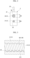
FIG. 2 is a sectional view showing the relationship between the screw shaft, the guide shaft and the moving body in the fader device ofFIG. 1 . -
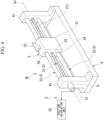
FIG. 3 is a diagram schematically showing the relationship between the male thread of the screw shaft and the female thread of the moving body in the fader device ofFIG. 1 . -
FIG. 4 is a perspective view showing a fader device according to the second embodiment of the present invention. -
FIG. 5 is a sectional view showing the relationship between the screw shaft, the guide shaft and the moving body in the fader device ofFIG. 4 . -
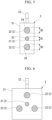
FIG. 6 is a sectional view showing a modification of the fader device ofFIGS. 4 and5 . -
FIG. 7 is a perspective view showing a fader device according to the third embodiment of the present invention. -
FIG. 8 is a perspective view showing a state in which the partition member is removed in the fader device ofFIG. 7 . -
FIG. 9 is a perspective view showing a state in which a cover member is removed from the fader device ofFIG. 8 . -
FIG. 10 is a perspective view of the fader device ofFIG. 8 viewed from a different angle. -
FIG. 11 is a cross-sectional view taken along line XI-XI inFIG. 7 . -
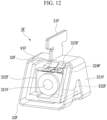
FIG. 12 is a perspective view showing the moving body in the fader device ofFIGS. 7 to 11 . - A first embodiment of the present invention will be described below with reference to
FIGS. 1 to 3 . - As shown in
FIG. 1 , afader device 1 according to the first embodiment includes a plurality ofshafts 2 and a moving body3. Thefader device 1 also includes a base 4. - The plurality of
shafts 2 are each formed in a rod shape extending in a straight line direction. The plurality ofshafts 2 are arranged parallel to each other. Further, the plurality ofshafts 2 are spaced apart from each other when viewed in the longitudinal direction of the shafts 2 (seeFIG. 2 ). In the present embodiment, the plurality ofshafts 2 are arranged spaced apart in a row in a direction perpendicular to the longitudinal direction of theshafts 2. - Both end portions of the plurality of
shafts 2 in the longitudinal direction are supported by the base 4. The base 4 has a pair ofsupport portions 41 spaced apart in the longitudinal direction of theshafts 2. Both end portions of theshafts 2 in the longitudinal direction are inserted or passed through the pair ofsupport portions 41. The plurality ofshafts 2 are thereby supported by the base 4. The base 4 including the pair ofsupport portions 41 may be configured by, for example, a housing (case) that accommodates the plurality ofshafts 2 and amain body portion 31 of the movingbody 3 to be described later. - The number of
shafts 2 in the present embodiment is two. - One of the two
shafts 2 is ascrew shaft 21. Thescrew shaft 21 has amale thread 211 on the outer circumference thereof. Themale thread 211 may be a single thread or a multi-threaded thread. Thescrew shaft 21 is rotatable around anaxis A 1 extending in the longitudinal direction of theshafts 2. In the present embodiment, the pair ofsupport portions 41 that support both end portions in the longitudinal direction of thescrew shaft 21 function as bearings that rotatably support thescrew shaft 21, - The other one of the two
shafts 2 is a guide shaft 22 (guide member). Theguide shaft 22 is configured to guide the movingbody 3, to be described later, in the longitudinal direction of theshafts 2. Theguide shaft 22 also serves to prevent the moving body3 from rattling with respect to thescrew shaft 21 and the base 4 in the direction orthogonal to the longitudinal direction of theshafts 2. Theguide shaft 22 is formed in a rod-like shape with no irregularities such as themale thread 211 on the outer circumference thereof. Theguide shaft 22 may be formed in, for example, a polygonal prismatic shape, but is formed in a columnar shape in this embodiment. - As shown in
FIG. 2 , the diameter D2 of theguide shaft 22 is larger than the diameter D1 of thescrew shaft 21. Note that the diameter D2 of theguide shaft 22 may be substantially equal to the diameter D1 of thescrew shaft 21, for example. - As shown in
FIG. 1 , the moving body3 is attached to the plurality ofshafts 2 so as to be movable in the longitudinal direction of theshafts 2 with respect to the plurality ofshafts 2. The movingbody 3 of the present embodiment has amain body portion 31 and anoperation portion 32 extending from themain body portion 31. Themain body portion 31 is formed with a plurality of throughholes shafts 2 are individually inserted. The number of throughholes shafts 2. The plurality of throughholes shafts 2. The plurality of throughholes hole 33 through which thescrew shaft 21 is inserted and a second throughhole 34 through which theguide shaft 22 is inserted. - The moving
body 3 is configured to mesh with themale thread 211 of thescrew shaft 21 so as to move in the longitudinal direction of theshafts 2 as thescrew shaft 21 rotates, by meshing with themale thread 211 of thescrew shaft 21. - As shown in
FIG. 3 , the movingbody 3 has an engagingportion 35 that engages themale thread 211 of thescrew shaft 21. The engagingportion 35 is provided on the inner periphery of the first throughhole 33 of the movingbody 3 through which thescrew shaft 21 is inserted. The engagingportion 35 of this embodiment is afemale thread 351 formed on the inner circumference of the first throughhole 33 of the movingbody 3.Female thread 351 may be a single thread or a multiple-threaded thread corresponding tomale thread 211. - The
female thread 351 of themain body 31 meshes with themale thread 211 of thescrew shaft 21, so that the movingbody 3 can move in the longitudinal direction of the shafts 2 (horizontal direction inFIG. 3 ) as thescrew shaft 21 rotates. As shown inFIGS. 1 and2 , since the movingbody 3 is also supported by theguide shaft 22 separate from thescrew shaft 21, so that even if thescrew shaft 21 rotates, the movingbody 3 is prevented from rotating with thescrew shaft 21 around the axis A1. - The
operation portion 32 of the movingbody 3 is a part that the operator touches with fingers to move the movingbody 3 manually. The operatingportion 32 extends in a direction perpendicular to the longitudinal direction of theshafts 2 with respect to themain body portion 31. In the present embodiment, the operatingportion 32, thescrew shaft 21, and theguide shaft 22 are arranged in a row in a direction orthogonal to the longitudinal direction of the shafts 2 (vertical direction inFIG. 2 ). - As shown in
FIG. 1 , the fader device I of the present embodiment further includes aposition measuring unit 5 that measures the position of the movingbody 3 in the longitudinal direction of theshaft 2. Theposition measuring unit 5 of the present embodiment includes anencoder 51. A shaft (not shown) of theencoder 51 is coupled to thescrew shaft 21. Theencoder 51 measures the rotation angle of thescrew shaft 21. - The
position measuring unit 5 further includes aposition calculation unit 52. Theposition calculation unit 52 calculates the position of the movingbody 3 in the longitudinal direction of theshafts 2 based on the rotation angle of thescrew shaft 21 measured by theencoder 51. Thereby, the position of the movingbody 3 in the longitudinal direction of theshafts 2 can be measured. - The
fader device 1 of the present embodiment further includes amotor 6 that rotationally drives thescrew shaft 21. A drive shaft (not shown) of themotor 6 is coupled to thescrew shaft 21. Themotor 6 may be, for example, a stepping motor capable of positioning the movingbody 3 with high accuracy. InFIG. 1 , themotor 6 is arranged between thescrew shaft 21 and theencoder 51. For this reason, the shaft of theencoder 51 is coupled to thescrew shaft 21 via the drive shaft of themotor 6. - As described above, in the
fader device 1 of the present embodiment, the movingbody 3 can be moved in the longitudinal direction of theshafts 2 by rotationally driving thescrew shaft 21 with the driving force of themotor 6. On the other hand, when the operator grasps theoperation portion 32 and manually moves the movingbody 3 in the longitudinal direction of theshafts 2, thescrew shaft 21 rotates. - Thus, the structure in which the
screw shaft 21 rotates with the movement of the movingbody 3 can reduce the resistance when the operator moves the movingbody 3 manually (resistance to the movement of the moving body 3), compared to the conventional structure in which an endless belt wound around a plurality of pulleys moves as the movingbody 3 moves. Thereby, the operational feeling of the movingbody 3 can be improved. - Further, in the
fader device 1 of the present embodiment, the movingbody 3 meshes with themale thread 211 of thescrew shaft 21. For that reason, the movingbody 3 does not slip on thescrew shaft 21 and there is no skipping of teeth. That is, it becomes possible to move the movingbody 3 with high accuracy by themotor 6. - Further, the
fader device 1 of the present embodiment eliminates the need for strict adjustment of tension in the conventional structure that utilizes an endless belt. Therefore, it is possible to reduce the number of man-hours for manufacturing thefader device 1 and to keep manufacturing costs low. - Further, in the
fader device 1 of the present embodiment, the diameter D1 of thescrew shaft 21 is smaller than the diameter D2 of theguide shaft 22. Since thescrew shaft 21 is thin, the friction generated between thescrew shaft 21 and the movingbody 3 can be kept small. As a result, the resistance when the operator manually moves the movingbody 3 can be further reduced, and the operational feeling of the movingbody 3 can be further improved. - The
fader device 1 of the present embodiment also has only twoshafts 2 attached to the movingbody 3. By attaching the movingbody 3 to these twoshafts 2, the orientation of the movingbody 3 can be maintained so that the movingbody 3 does not rotate around theshafts 2. One of the twoshafts 2 is ascrew shaft 21 for moving the moving body in the longitudinal direction of theshafts 2. Therefore, compared with the conventional structure using an endless belt, there is no need to separately provide a component for moving the movingbody 3 by themotor 6, and so the number of constituent parts of thefader device 1 can be reduced. - Further, in the
fader device 1 of the present embodiment, theposition measuring unit 5 that measures the position of the movingbody 3 in the longitudinal direction of theshaft 2 has anencoder 51 that measures the rotation angle of thescrew shaft 21. Thereby, the length of travel of the movingbody 3 in the longitudinal direction of theshafts 2 can be calculated based on the rotation angle of thescrew shaft 21 measured by theencoder 51. Therefore, the position of the movingbody 3 can be measured. - Further, as described above, since the moving
body 3 does not slip on thescrew shaft 21 and there is no skipping of teeth, the position of the movingbody 3 can be measured by theposition measuring unit 5 with high accuracy. - In addition, the
encoder 51 used as theposition measuring unit 5 can reduce the number of parts constituting theposition measuring unit 5 and achieve space savings of theposition measuring unit 5 compared to a structure that directly measures the position of the movingbody 3 that linearly moves. As a result, the size of thefader device 1 can be easily reduced. - In the first embodiment, the
operation portion 32, thescrew shaft 21, and theguide shaft 22 are arranged in a row in a direction perpendicular to the longitudinal direction of the shafts 2 (vertical direction inFIG. 2 ), but it is not limited thereto. For example, the direction in which thescrew shaft 21 and theguide shaft 22 are aligned may be orthogonal (left-right direction inFIG. 2 ) to the direction in which theoperation portion 32 and the shaft 2 (screwshaft 21 or guide shaft 22) are aligned (vertical inFIG. 2 ). However, in this case, since the dimensions (width dimension) of thefader device 1 in the left-right direction are larger, it is more preferable to have theoperation portion 32,screw shaft 21, and guideshaft 22 arranged in a row in the vertical direction, as illustrated inFIG. 2 . - Next, a second embodiment of the present invention will be described with reference to
FIGS. 4 and5 . In the following description, the same reference numerals are given to the same configurations as those already described, and redundant descriptions will be omitted. - As shown in
FIG. 4 , afader device 1E according to the second embodiment includes a plurality ofshafts 2, a moving body3, and a base 4, as in the first embodiment. The plurality ofshafts 2 include ascrew shaft 21 and guideshafts 22 similar to those in the first embodiment. - However, the
fader device 1E of the second embodiment has a plurality ofguide shafts 22. As shown inFIG. 5 , the plurality ofguide shafts 22 are arranged so as to surround thescrew shaft 21 when viewed from the longitudinal direction of theshafts 2. For example, the plurality ofguide shafts 22 may be arranged at regular intervals in the circumferential direction around thescrew shaft 21 when viewed from the longitudinal direction of theshafts 2. - The number of
guide shafts 22 in the second embodiment is two. The twoguide shafts 22 are equally spaced (180 degrees apart) in the circumferential direction around thescrew shaft 21 when viewed from the longitudinal direction of theshafts 2. Therefore, thescrew shaft 21 is positioned between the twoguide shafts 22 when viewed in the longitudinal direction of theshafts 2. That is, thescrew shaft 21 and the twoguide shafts 22 are arranged in a row in a direction orthogonal to the longitudinal direction of theshafts 2. In particular, in the present embodiment, theoperation portion 32, thescrew shaft 21, and the twoguide shafts 22 are arranged in a row in the direction perpendicular to the longitudinal direction of the shafts 2 (vertical direction inFIG. 5 ). As a result, the width dimension of thefader device 1E in the left-right direction inFIG. 5 can be kept small. - According to the
fader device 1E of the second embodiment, the same effects as those of the first embodiment are achieved. - Further, in the
fader device 1E of the second embodiment, the plurality ofguide shafts 22 are arranged so as to surround thescrew shaft 21 when viewed from the longitudinal direction of theshafts 2. Therefore, the load when the operator manually moves the movingbody 3 is more likely to act on themultiple guide shafts 22. As a result, the load acting on thescrew shaft 21 can be reduced. Therefore, it is possible to form thescrew shaft 21 thinner. Thereby, the friction generated between thescrew shaft 21 and the movingbody 3 can be further suppressed. Accordingly, the resistance when moving the movingbody 3 manually can be further reduced, and the operational feeling of the movingbody 3 can be further improved. - In the
fader device 1E of the second embodiment, the number of theguide shafts 22 may be three or more. In this case, three ormore guide shafts 22 may be arranged at regular intervals in the circumferential direction around thescrew shaft 21 when viewed from the longitudinal direction of theshafts 2, as illustrated inFIG. 6 . However, in this case, the width dimension of thefader device 1 in the horizontal direction tends to increase. For this reason, three ormore guide shafts 22 may be arranged at uneven intervals in the circumferential direction around thescrew shaft 21 so that the width dimension of thefader device 1 is reduced, for example. - In the fader devices of the first and second embodiments, the
guide shaft 22 is not limited to being inserted through the second throughhole 34 of the movingbody 3, and for example may be provided to support the moving body 3 (main body portion 31) from the outside thereof. - In the fader devices of the first and second embodiments, the
position measuring unit 5 that measures the position of the movingbody 3 is not limited to the configuration that measures the position of the movingbody 3 based on the rotational position of thescrew shaft 21, but may also be configured to directly measure the position of the movingbody 3, for example. - Next, a third embodiment of the present invention will be described with reference to
FIGS. 7 to 12 . In the following description, the same reference numerals are given to the same configurations as those already described, and redundant descriptions will be omitted. - As shown in
FIGS. 7 and8 , afader device 1F according to the third embodiment includes ascrew shaft 21, a movingbody 3F, apartition member 7F, and acover member 8F. Further, thefader device 1F further includes a pair ofsupport portions 41F and amotor 6. - The
screw shaft 21 shown inFIGS. 8 to 10 is formed in a rod shape extending in a straight line and has amale thread 211 on the outer circumference thereof, as in the first and second embodiments. Both end portions of thescrew shaft 21 in the longitudinal direction are supported by the pair ofsupport portions 41F so that thescrew shaft 21 can rotate about the axis A1. - The
motor 6 rotationally drives thescrew shaft 21 as in the first and second embodiments. Themotor 6 is attached to onesupport portion 41F. - The moving
body 3F is attached to thescrew shaft 21 as in the first and second embodiments. Further, the movingbody 3F is configured to mesh with themale thread 211 of thescrew shaft 21 so as to move in the longitudinal direction (linear direction) of thescrew shaft 21 as thescrew shaft 21 rotates. Although not shown, the aspect of the movingbody 3F that engages with themale thread 211 of thescrew shaft 21 may be the same as that of the first embodiment (for example, the engagingportion 35 illustrated inFIG. 3 ). - A specific configuration of the moving
body 3F will be described later. - As shown in
FIGS. 7 ,8 and11 , thepartition member 7F forms a partition into a first region R1 where thescrew shaft 21 is arranged and a second region R2 different from the first region R1. Thepartition member 7F has aninsertion hole 71F through which a portion of the movingbody 3F attached to thescrew shaft 21 is inserted from the first region R1 side to the second region R2 side. Theinsertion hole 71F extends in the longitudinal direction of the screw shaft 21 (that is, the moving direction of the movingbody 3F). Although thepartition member 7F of the present embodiment is a panel member formed in a flat plate shape, it is not limited thereto. - In the following description, the direction perpendicular to the longitudinal direction of the
screw shaft 21 and in which the first region R1 and the second region R2 partitioned by thepartition member 7F are aligned is sometimes called the vertical direction. In addition, in the vertical direction, the side of the first region R1 may be called the lower side or below, and the side of the second region R2 is sometimes called the upper side or above. Also, as shown inFIG. 11 , the direction perpendicular to the vertical direction when viewed from the longitudinal direction of thescrew shaft 21 is sometimes called the left-right direction. - As shown in
FIG. 11 , theinsertion hole 71F of thepartition member 7F is positioned so as to overlap thescrew shaft 21 when viewed from the vertical direction. That is, theinsertion hole 71F is positioned so as not to shift in the left-right direction with respect to thescrew shaft 21. Note that theinsertion hole 71F may be shifted in the left-right direction with respect to thescrew shaft 21, for example. - The
cover member 8F is positioned in the first region R1 between thescrew shaft 21 and theinsertion hole 71F of thepartition member 7F. As shown inFIGS. 7 and8 , thecover member 8F extends in the longitudinal direction of thescrew shaft 21 and theinsertion hole 71F of thepartition member 7F between thescrew shaft 21 and theinsertion hole 71F. The extending direction of thecover member 8F is parallel to the longitudinal direction of thescrew shaft 21. - As shown in
FIGS. 8 to 11 , thecover member 8F is formed in a tubular shape extending in the longitudinal direction of thescrew shaft 21. Thetubular cover member 8F surrounds thescrew shaft 21. Both longitudinal end portions of thecover member 8F are fixed to the pair ofsupport portions 41F. Thereby, the relative positions of thecover member 8F and thescrew shaft 21 are fixed. - The
cover member 8F may have a cylindrical shape, but in the present embodiment has a polygonal tubular shape. Specifically, thecover member 8F is formed in a rectangular tubular shape having vertical sides extending in the vertical direction and horizontal sides extending in the horizontal direction. - As shown in
FIGS. 10 and11 , thecover member 8F has along hole 81F (coupling hole) extending in the longitudinal direction thereof. Thelong hole 81F of thecover member 8F connects the inner side and the outer side of thecylindrical cover member 8F. Thelong hole 81F is not located between thescrew shaft 21 and theinsertion hole 71F of thepartition member 7F when viewed from the longitudinal direction of thescrew shaft 21 as shown inFIG. 11 . That is, thelong hole 81F is located outside the region between thescrew shaft 21 and theinsertion hole 71F of thepartition member 7F. Since thelong hole 81F is positioned in this way, thescrew shaft 21 cannot be seen from the second region R2 side through theinsertion hole 71F of thepartition member 7F and thelong hole 81F of thecover member 8F. - Specifically, the
long hole 81F faces the opposite side (downward) to thepartition member 7F. Note that thelong hole 81F of thecover member 8F may face, for example, in the left-right direction, or may face towards thepartition member 7F side (upper side). - A specific configuration of the moving
body 3F will be described below. - As shown in
FIGS. 9 to 12 , the movingbody 3F includes aninsertion portion 31F, a mountingportion 32F, and acoupling portion 33F. The mountingportion 32F and thecoupling portion 33F are positioned on the side of the first region R1 side partitioned by thepartition member 7F, and theinsertion portion 31F is inserted through theinsertion hole 71F of thepartition member 7F. As a result, part of theinsertion portion 31F is positioned on the second region R2 side. The portion of theinsertion portion 31F positioned on the second region R2 side functions as the operation portion that is touched by the fingers of the operator of thefader device 1F in order to manually move the movingbody 3F. - The mounting
portion 32F of the movingbody 3F is a portion that meshes with themale thread 211 of thescrew shaft 21, and has an engaging portion that engages with themale thread 211, similar to themain body portion 31 of the movingbody 3 of the first embodiment. Specifically, the mountingportion 32F of the movingbody 3F has a throughhole 321F through which thescrew shaft 21 is inserted. Although not shown, the engaging portion of the mountingportion 32F is a female thread formed on the inner periphery of the throughhole 321F of the mountingportion 32F. - As shown in
FIG. 11 , thecover member 8F is interposed between the mountingportion 32F and theinsertion portion 31F. In the present embodiment, the mountingportion 32F is positioned below theinsertion portion 31F with a space therebetween, and thecover member 8F is interposed between theinsertion portion 31F and the mountingportion 32F which are vertically aligned. - In addition, the mounting
portion 32F is arranged inside thetubular cover member 8F together with thescrew shaft 21. The mountingportion 32F is exposed to the outside of thecover member 8F through thelong hole 81F of thecover member 8F that opens downward. - The external shape of the mounting
portion 32F viewed from the longitudinal direction of thescrew shaft 21 corresponds to the shape of the inner periphery of thecylindrical cover member 8F. That is, the external shape of the mountingportion 32F when viewed from the longitudinal direction of thescrew shaft 21 is formed in a rectangular shape (polygonal shape) generally corresponding to the shape of the inner periphery of thecover member 8F. In addition, the size of the mountingportion 32F when viewed from the longitudinal direction of thescrew shaft 21 is slightly smaller than the size of the inner circumference of thecover member 8F. Accordingly, the mountingportion 32F is locked to thecover member 8F in the rotation direction of thescrew shaft 21. That is, thecover member 8F prevents the mountingportion 32F from rotating together with thescrew shaft 21. - As shown in
FIGS. 9 to 12 , thecoupling portion 33F couples the above-mentionedinsertion portion 31F and the mountingportion 32F. As described above, thecover member 8F is interposed between theinsertion portion 31F and the mountingportion 32F. Therefore, thecoupling portion 33F is formed so as to bypass thecover member 8F when viewed from the longitudinal direction of thescrew shaft 21, as shown inFIG. 11 . That is, thecoupling portion 33F is formed to extend in the left-right direction with respect to theinsertion portion 31F and the mountingportion 32F so as not to be positioned between theinsertion hole 71F of thepartition member 7F and thecover member 8F when viewed from the longitudinal direction of thescrew shaft 21. - The
coupling portion 33F couples theinsertion portion 31F and the mountingportion 32F by being inserted through thelong hole 81F of thecover member 8F. That is, thelong hole 81F of thecover member 8F functions as a coupling hole that couples theinsertion portion 31F and the mountingportion 32F. - As shown in
FIGS. 11 and12 , thecoupling portion 33F has anannular portion 331F that surrounds the outer side of the mountingportion 32F when viewed from the longitudinal direction of thescrew shaft 21. Theinsertion portion 31F is connected to the upper end of theannular portion 331F. Further, the lower end of theannular portion 331F is connected to the insertion portion of thecoupling portion 33F that passes through thelong hole 81F of thecover member 8F and that is connected to the mountingportion 32F. Theinsertion portion 31F extends above theannular portion 331F in the middle in the left-right direction of theannular portion 331F. The insertion portion of thecoupling portion 33F extends upward from the inner surface of theannular portion 331F facing upward in the middle of theannular portion 331F in the left-right direction. - As shown in
FIGS. 8 to 11 , thescrew shaft 21 and thecover member 8F are inserted through theannular portion 331F. Theannular portion 331F is locked to thecover member 8F in the rotation direction of thescrew shaft 21. This point will be described below. - As shown in
FIG. 11 , the shape of theannular portion 331F viewed from the longitudinal direction of thescrew shaft 21 corresponds to the shape of the outer periphery of thecover member 8F. That is, the shape of theannular portion 331F viewed from the longitudinal direction of thescrew shaft 21 is formed in a rectangular shape (polygonal shape) corresponding to the shape of the outer periphery of thecover member 8F. Also, the size of theannular portion 331F when viewed from the longitudinal direction of thescrew shaft 21 is slightly larger than the size of the outer periphery of thecover member 8F. Thereby, theannular portion 331F is locked to thecover member 8F in the rotation direction of thescrew shaft 21. That is, thecover member 8F prevents theannular portion 331F from rotating together with thescrew shaft 21. - The moving
body 3F configured as described above is attached to both thescrew shaft 21 and thecover member 8F so as to be movable in the longitudinal direction of thescrew shaft 21, - In the moving
body 3F of the present embodiment, theinsertion portion 31F and the mountingportion 32F are electrically connected via thecoupling portion 33F. This point will be described below. - In the moving
body 3F of this embodiment shown inFIGS. 11 and12 , theinsertion portion 31F and theannular portion 331F of thecoupling portion 33F are integrally formed of an electrically conductive member such as metal. A part of the mountingportion 32F and the insertion portion of thecoupling portion 33F passing through thelong hole 81F of thecover member 8F are formed by aconductive member 322F having electrical conductivity such as metal. Theconductive member 322F is connected to the conductiveannular portion 331F. Thereby, theinsertion portion 31F and the mountingportion 32F are electrically connected. Note that the mountingportion 32F also has aconnection terminal 323F that is connected to theconductive member 322F and extends to asubstrate 82F, which will be described later. - The specific aspect of the
conductive member 322F may be arbitrary. Theconductive member 322F of the present embodiment is formed by bending a plate material. Also, theconductive member 322F is sealed in a resin moldedportion 324F that forms the outer shape of the mountingportion 32F. - In the
fader device 1F of the present embodiment, the structure electrically connecting theinsertion portion 31F and the mountingportion 32F is used for a touch sensor to detect whether the operator of thefader device 1F touches the movingbody 3F (insertion portion 31F). This point will be described below. - As shown in
FIGS. 9 and11 , thesubstrate 82F extending in the longitudinal direction of thescrew shaft 21 is provided on the surface of thecover member 8F facing the mountingportion 32F. Although not shown, thesubstrate 82F is formed with connection wiring extending in the longitudinal direction of thescrew shaft 21 and electrically connected to theconnection terminal 323F of the mountingportion 32F. This connection wiring is connected to an electric circuit (contact detection circuit; not shown) for detecting contact of the operator's fingers with theinsertion portion 31F of the movingbody 3F. The contact detection circuit detects whether or not there is contact with theinsertion portion 31F based on an electrical change (for example, a change in capacitance). - The
fader device 1F of the present embodiment further includes aposition detection unit 9F that detects the position of the movingbody 3F in the longitudinal direction of thescrew shaft 21. Theposition detection unit 9F has a resistor (not shown) and aresistive element 91F made of conductors. The resistor is provided on thecover member 8F. In the present embodiment, the resistor is electrical wiring, not shown, formed on thesubstrate 82F described above. Theresistive element 91F is provided on the movingbody 3F and contacts the resistor provided on thecover member 8F. In the present embodiment, theresistive element 91F is provided on the mountingportion 32F of the movingbody 3F. Theresistive element 91F is electrically insulated from theconductive member 322F and theconnection terminal 323F described above. As theresistive element 91F moves in the longitudinal direction of thescrew shaft 21 together with the movingbody 3F, the resistor can detect the position of theresistive element 91F in the longitudinal direction of thescrew shaft 21. - As shown in
FIG. 11 , thesubstrate 82F including the connection wiring for the touch sensor and the resistor for theposition detection unit 9F is provided on a surface of thecover member 8F facing thescrew shaft 21. In the present embodiment, thesubstrate 82F is provided on the inner surface of thecylindrical cover member 8F. Further, thesubstrate 82F is arranged on the surface of thecover member 8F facing the opposite side (downward) of thepartition member 7F. - The
substrate 82F is fixed to thecover member 8F. The method for fixing thesubstrate 82F to thecover member 8F may be any method such as caulking, screwing, or adhesion. - In the
fader device 1F of the third embodiment, similarly to the first and second embodiments, the movingbody 3F can be moved in the longitudinal direction of thescrew shaft 21 by rotationally driving thescrew shaft 21 with themotor 6. On the other hand, when the operator grabs the movingbody 3F (operation portion) and manually moves it in the longitudinal direction of thescrew shaft 21, thescrew shaft 21 rotates. - According to the
fader device 1F of the third embodiment, the same effects as those of the first and second embodiments are obtained. - Further, in the
fader device 1F of the third embodiment, thecover member 8F is interposed between thescrew shaft 21 and theinsertion hole 71F of thepartition member 7F in the first region R1 where thescrew shaft 21 is arranged. Therefore, even if dust enters the first region R1 through theinsertion hole 71F of thepartition member 7F from the second region R2, the dust can be prevented from reaching thescrew shaft 21 by thecover member 8F. That is, it becomes difficult for dust to adhere to themale thread 211 of thescrew shaft 21. As a result, the operation of thescrew shaft 21 and the movingbody 3F (for example, the movement of the movingbody 3F accompanying the rotation of the screw shaft 21) can be effectively prevented from being hindered by dust. - Further, in the
fader device 1F of the third embodiment, the movingbody 3F includes theinsertion portion 31F inserted through theinsertion hole 71F of thepartition member 7F, the mountingportion 32F that meshes with themale thread 211 of thescrew shaft 21, and thecoupling portion 33F that couples theinsertion portion 31F and the mountingportion 32F. Thecoupling portion 33F is formed so as to bypass thecover member 8F interposed between theinsertion portion 31F and the mountingportion 32F. As a result, even if thecover member 8F is interposed between thescrew shaft 21 and theinsertion hole 71F of thepartition member 7F, the movingbody 3F attached to thescrew shaft 21 on the first region R1 side can be passed through theinsertion hole 71F of thepartition member 7F. - Further, the
coupling portion 33F is formed so as to bypass thecover member 8F when viewed from the longitudinal direction of thescrew shaft 21. Therefore, thecoupling portion 33F does not hinder the movement of the movingbody 3F in the longitudinal direction of thescrew shaft 21. - Further, in the
fader device 1F of the third embodiment, thelong hole 81F (coupling hole) of thecover member 8F, which extends in the longitudinal direction of thescrew shaft 21 and through which thecoupling portion 33F is inserted, is located outside the region between thescrew shaft 21 and theinsertion hole 71F of thepartition member 7F, viewed from the longitudinal direction of thescrew shaft 21. That is, thelong hole 81F of thecover member 8F is not positioned between thescrew shaft 21 and theinsertion hole 71F of thepartition member 7F. For this reason, even if dust enters the first region R1 through theinsertion hole 71F of thepartition member 7F from the second region R2, the dust can effectively be prevented from reaching thescrew shaft 21 through the coupling hole of thecover member 8F. In addition, since thelong hole 81F of thecover member 8F faces the side opposite to thepartition member 7F, it is possible to further prevent the dust from reaching thescrew shaft 21. As a result, it is possible to more effectively prevent dust from adhering to themale thread 211 of thescrew shaft 21. - In addition, in the
fader device 1F of the third embodiment, theannular portion 331F of thecoupling portion 33F through which thecover member 8F is inserted is locked to thecover member 8F in the rotational direction of thescrew shaft 21. Therefore, it is possible to prevent the movingbody 3F from rotating around the axis A1 of thescrew shaft 21. That is, the position of the movingbody 3F in the rotation direction of thescrew shaft 21 can be maintained. In other words, thecover member 8F functions as a guide member that guides the movingbody 3F in the longitudinal direction of thescrew shaft 21 while maintaining the orientation of the movingbody 3F. - Here, in the
fader device 1F of the third embodiment, the mountingportion 32F of the movingbody 3F is also locked to thecover member 8F in the rotational direction of thescrew shaft 21, as with theannular portion 331F. That is, the mountingportion 32F that is locked to thecover member 8F can also prevent the movingbody 3F from rotating about the axis A1 of thescrew shaft 21. - Further, in the
fader device 1F of the third embodiment, theinsertion portion 31F of the movingbody 3F and the mountingportion 32F are electrically connected via thecoupling portion 33F. Accordingly, the movingbody 3F can be used for a touch sensor that detects whether or not the operator touches the movingbody 3F (operation portion). - Further, in the
fader device 1F of the third embodiment, the connection wiring for the touch sensor and the resistor for theposition detection unit 9F provided on thesubstrate 82F are arranged on the surface of thecover member 8F facing thescrew shaft 21. For this reason, even if dust enters the first region R1 from the second region R2 through theinsertion hole 71F of thepartition member 7F, thecover member 8F can prevent the dust from reaching the connection wiring and the resistor (substrate 82F). That is, it becomes difficult for dust to adhere to the connection wiring and the resistor. As a result, it is possible to prevent the touch sensor and the position detection unit 9 from malfunctioning due to dust. - In the third embodiment, the structure of the
coupling portion 33F for bypassing thecover member 8F is not limited to theannular portion 331F (a structure formed in an O shape when viewed from the longitudinal direction of the screw shaft 21). The structure of thecoupling portion 33F for bypassing thecover member 8F may be, for example, a C-shaped or L-shaped structure when viewed from the longitudinal direction of thescrew shaft 21. - Even if the structure of the
coupling portion 33F that bypasses thecover member 8F has a C-shaped or L-shaped structure, thecoupling portion 33F can be locked to thelong hole 81F of thecover member 8F in the rotational direction of thescrew shaft 21 if thecoupling portion 33F bypasses thecover member 8F and passes through thelong hole 81F of thecover member 8F facing away from thepartition member 7F. That is, it is possible to prevent the movingbody 3F from rotating around theaxis A 1 of thescrew shaft 21. - In the third embodiment, the
cover member 8F is not limited to a tubular shape, and may be formed in a plate shape, for example. The plate-shapedcover member 8F may be arranged, for example, such that the thickness direction of thecover member 8F coincides with the direction (vertical direction) in which thepartition member 7F and thescrew shaft 21 are arranged. Further, along hole 81F (coupling hole) through which thecoupling portion 33F of the movingbody 3F passes may be formed in the plate-shapedcover member 8F, as in the above-described third embodiment. Thelong hole 81F formed in the plate-shapedcover member 8F may be positioned outside the region between thescrew shaft 21 and theinsertion hole 71F of thepartition member 7F when viewed from the longitudinal direction of thescrew shaft 21. For example, thelong hole 81F of thecover member 8F may be positioned laterally offset from thescrew shaft 21. Thereby, even if dust enters the first region R1 through theinsertion hole 71F of thepartition member 7F from the second region R2, the dust can be prevented from reaching thescrew shaft 21 through thelong hole 81F of thecover member 8F. - Although the present invention has been described in detail above, the present invention is not limited to the above embodiments, and various modifications can be made without departing from the scope of the present invention.
- In the fader device of the present invention, the engaging
portion 35 of the movingbody female thread 351, but may be an engaging projection that enters and engages with the groove of themale thread 211. Also, the engagingportion 35 of the movingbody screw shaft 21, for example. - In the fader device of the present invention, the
screw shaft 21 is not limited to being inserted through the throughhole body body main body 31 in the first and second embodiments, and the mountingportion 32F in the third embodiment). In this case, the engagingportion 35 of the movingbody main body portion 31 and the mountingportion 32F to engage with themale thread 211, for example. - The fader device of the present invention may include a plurality of
screw shafts 21, for example. That is, by rotating a plurality of thescrew shafts 21, one movingbody shafts 2 or thescrew shafts 21. - In the fader device of the present invention, the screw of the
screw shaft 21 that meshes with the movingbody -
- 1, 1E, 1F
- Fader device
- 2
- Shaft
- 3, 3F
- Moving body
- 5
- Position measuring unit
- 6
- Motor
- 7F
- Partition member
- 8F
- Cover member (guide member)
- 9F
- Position detection unit
- 21
- Screw shaft
- 22
- Guide shaft
- 31F
- Insertion portion
- 32F
- Mounting portion
- 33F
- Coupling portion
- 51
- Encoder
- 71F
- Insertion hole
- 81F
- Long hole (coupling hole)
- 82F
- Substrate
- 91F
- Resistance element
- 211
- Male thread
- 331F
- Annular portion
- A1
- Axis of
screw shaft 21 - D1
- Diameter of
screw shaft 21 - D2
- Diameter of
guide shaft 22 - R1
- First region
- R2
- Second region
Claims (15)
- A fader device comprising:a plurality of shafts that are parallel to each other; anda moving body that is attached to the plurality of shafts so as to be capable of moving in a longitudinal direction of the plurality of shafts,wherein at least one of the plurality of shafts is a screw shaft having a male thread on an outer periphery thereof and being configured to be rotatable about an axis extending along the longitudinal direction,the other shaft that is the plurality of shafts other than the screw shaft is a guide shaft that guides the moving body in the longitudinal direction, andthe moving body, by meshing with the male thread, moves in the longitudinal direction as the screw shaft rotates.
- The fader device according to claim 1, wherein a diameter of the screw shaft is smaller than a diameter of the guide shaft.
- The fader device according to claim 1 or 2,wherein one each of the guide shaft and the screw shaft are provided, andthe guide shaft and the screw shaft are spaced apart from each other when viewed from the longitudinal direction.
- The fader device according to claim 1 or 2,wherein the fader device comprises a plurality of the guide shafts, andthe plurality of guide shafts are arranged so as to surround the screw shaft when viewed from the longitudinal direction.
- The fader device according to any one of claims 1 to 4, further comprising
a position measuring unit that measures a position of the moving body in the longitudinal direction. - The fader device according to claim 5, wherein the position measuring unit comprises an encoder that measures a rotation angle of the screw shaft.
- The fader device according to any one of claims 1 to 6, further comprising a motor that rotationally drives the screw shaft.
- A fader device comprising:a screw shaft extending in a linear direction, having a thread, and being rotatable about an axis extending in the linear direction;a guide member extending in the linear direction so as to be parallel to the screw shaft; anda moving body attached to the screw shaft and the guide member so to be movable in the linear direction;wherein the moving body, by meshing with the thread, moves in the linear direction as the screw shaft rotates.
- A fader device comprising:a screw shaft extending in a linear direction, having a male thread on an outer periphery thereof, and being rotatable about an axis extending in the linear direction;a moving body that is attached to the screw shaft and, by meshing with the male thread, moves in the linear direction as the screw shaft rotates;a partition member that separates a first region where the screw shaft is located from a second region that is different from the first region, the partition member having an insertion hole that extends in the linear direction and through which the moving body is inserted from a side of the first region to a side of the second region; anda cover member positioned between the screw shaft and the insertion hole of the partition member in the first region and extending in the linear direction.
- The fader device according to claim 9,wherein the moving body comprises an insertion portion that is inserted through the insertion hole, a mounting portion that meshes with the male thread, and a coupling portion that couples the insertion portion and the mounting portion,the cover member is interposed between the insertion portion and the mounting portion, andthe coupling portion is formed so as to bypass the cover member when viewed from the linear direction.
- The fader device according to claim 10,wherein the cover member has a coupling hole that extends in the linear direction and couples the insertion portion and the mounting portion by the coupling portion passing through the coupling hole, andthe coupling hole is positioned outside a region between the screw shaft and the insertion hole when viewed from the linear direction.
- The fader device according to claim 10,wherein the cover member is formed in a tubular shape surrounding the screw shaft and the mounting portion,the cover member has a long hole extending in the linear direction and connecting an inside and an outside of the cover member,the coupling portion is inserted in the long hole, andthe long hole faces an opposite side of the partition member.
- The fader device according to any one of claims 10 to 12,wherein the coupling portion has an annular portion surrounding an outer side of the mounting portion when viewed from the linear direction,the screw shaft and the cover member are inserted inside the annular portion, andthe annular portion is locked to the cover member in a rotational direction of the screw shaft.
- The fader device according to any one of claims 10 to 13, wherein the insertion portion and the mounting portion are electrically connected via the coupling portion.
- The fader device according to any one of claims 9 to 14, comprisinga position detection unit that detects a position of the moving body in the linear direction,the position detection unit comprises: a resistor comprising a conductor, provided on the cover member, and extends in the linear direction; and a resistance element comprising a conductor, provided on the moving body, and in contact with the resistor, andthe resistor is provided on a surface of the cover member facing the screw shaft.
Applications Claiming Priority (2)
| Application Number | Priority Date | Filing Date | Title |
|---|---|---|---|
| JP2021009488 | 2021-01-25 | ||
| PCT/JP2021/034344 WO2022158041A1 (en) | 2021-01-25 | 2021-09-17 | Fader device |
Publications (2)
| Publication Number | Publication Date |
|---|---|
| EP4283637A1 true EP4283637A1 (en) | 2023-11-29 |
| EP4283637A4 EP4283637A4 (en) | 2025-03-12 |
Family
ID=81206833
Family Applications (1)
| Application Number | Title | Priority Date | Filing Date |
|---|---|---|---|
| EP21921146.3A Withdrawn EP4283637A4 (en) | 2021-01-25 | 2021-09-17 | CROSS-FADER DEVICE |
Country Status (4)
| Country | Link |
|---|---|
| US (1) | US20230360826A1 (en) |
| EP (1) | EP4283637A4 (en) |
| JP (2) | JP7028380B1 (en) |
| CN (1) | CN116711035A (en) |
Families Citing this family (1)
| Publication number | Priority date | Publication date | Assignee | Title |
|---|---|---|---|---|
| CN115616131B (en) * | 2022-11-04 | 2025-12-19 | 帕斯卡尔(北京)流体科技有限公司 | High-precision injection pump |
Family Cites Families (17)
| Publication number | Priority date | Publication date | Assignee | Title |
|---|---|---|---|---|
| US2780776A (en) * | 1953-03-06 | 1957-02-05 | Bourns Inc | Linearity tester |
| JPS4018534B1 (en) * | 1963-12-30 | 1965-08-20 | ||
| JPS5587402A (en) * | 1978-12-25 | 1980-07-02 | Fuaasuto Denshi Yuugengaishiya | Sliding resistor |
| JPS6011407U (en) * | 1983-07-05 | 1985-01-25 | アルプス電気株式会社 | sliding variable resistor |
| US4489248A (en) * | 1983-07-25 | 1984-12-18 | Victory Enterprises Technology, Inc. | Linear actuator |
| US4583032A (en) * | 1984-08-17 | 1986-04-15 | Vernitron Corporation | Linear motion encoder |
| JPS6179063A (en) * | 1984-09-27 | 1986-04-22 | Fuji Xerox Co Ltd | Straight movement device |
| DE69211472T2 (en) * | 1991-08-01 | 1997-01-16 | Smc Kk | Linear guide unit and mount therefor |
| JPH0679105U (en) * | 1993-04-21 | 1994-11-04 | 東京光音電波株式会社 | Fader |
| JP4470194B2 (en) * | 2000-02-18 | 2010-06-02 | Smc株式会社 | Linear actuator |
| US6365642B1 (en) | 2000-10-10 | 2002-04-02 | The Procter & Gamble Company | Rapid preparation of foam materials from high internal phase emulsions |
| JP3488686B2 (en) * | 2000-12-05 | 2004-01-19 | Smc株式会社 | Actuator |
| JP4420046B2 (en) * | 2007-03-12 | 2010-02-24 | ヤマハ株式会社 | Slide operation device |
| JP2012207751A (en) * | 2011-03-30 | 2012-10-25 | Tsubaki Emerson Co | Linear drive device |
| EP2697525A1 (en) * | 2011-04-15 | 2014-02-19 | Ball Screws & Actuators Co. | Linear motion guided screw assembly |
| JP2016100371A (en) * | 2014-11-18 | 2016-05-30 | ヤマハ株式会社 | Operation device |
| JP7147365B2 (en) * | 2018-08-23 | 2022-10-05 | ヤマハ株式会社 | Fader device |
-
2021
- 2021-09-17 EP EP21921146.3A patent/EP4283637A4/en not_active Withdrawn
- 2021-09-17 CN CN202180090499.8A patent/CN116711035A/en active Pending
- 2021-09-17 JP JP2021558594A patent/JP7028380B1/en active Active
- 2021-11-29 JP JP2021193068A patent/JP7028360B1/en active Active
-
2023
- 2023-07-17 US US18/353,475 patent/US20230360826A1/en active Pending
Also Published As
| Publication number | Publication date |
|---|---|
| JP7028360B1 (en) | 2022-03-02 |
| JP7028380B1 (en) | 2022-03-02 |
| CN116711035A (en) | 2023-09-05 |
| JPWO2022158041A1 (en) | 2022-07-28 |
| US20230360826A1 (en) | 2023-11-09 |
| JP2022113639A (en) | 2022-08-04 |
| EP4283637A4 (en) | 2025-03-12 |
Similar Documents
| Publication | Publication Date | Title |
|---|---|---|
| US6720762B2 (en) | Rotation-angle detecting device capable of detecting absolute angle with simple configuration | |
| US20180373351A1 (en) | Input device, and input system employing same | |
| US12438417B2 (en) | Rotating device | |
| US20230360826A1 (en) | Fader device | |
| KR850001608B1 (en) | Sewing machine speed setting device | |
| CN1106699C (en) | Ribbon Cable Connectors for Bicycles | |
| US4646042A (en) | Speed and distance sensor | |
| JP2004020370A (en) | Torque detector | |
| KR101377383B1 (en) | Angle sensor arrangement | |
| JP4753545B2 (en) | Torque detection device and manufacturing method thereof | |
| EP1486753B1 (en) | Digital micrometer | |
| JP2002071302A (en) | Device for measuring length of linear movement | |
| WO2022158041A1 (en) | Fader device | |
| US5149273A (en) | Clock spring | |
| TW202138243A (en) | Electronic cable puller | |
| US20260088236A1 (en) | Operation device | |
| JP2019124577A (en) | Sensor and method for measuring turning force | |
| JP3485912B2 (en) | Electric motor | |
| CN103489552B (en) | Rotary actuator and electronic equipment | |
| US12630258B2 (en) | Bicycle rear derailleur and transmission assembly of bicycle device | |
| CN224204901U (en) | Linear type servo electric cylinder | |
| KR101062745B1 (en) | Multi-contact switch | |
| US20240174325A1 (en) | Bicycle rear derailleur and transmission assembly of bicycle device | |
| CN108394511B (en) | Electronic speed-changing angle sensing structure | |
| WO2016123834A1 (en) | High precision wound electric potential device |
Legal Events
| Date | Code | Title | Description |
|---|---|---|---|
| STAA | Information on the status of an ep patent application or granted ep patent |
Free format text: STATUS: THE INTERNATIONAL PUBLICATION HAS BEEN MADE |
|
| PUAI | Public reference made under article 153(3) epc to a published international application that has entered the european phase |
Free format text: ORIGINAL CODE: 0009012 |
|
| STAA | Information on the status of an ep patent application or granted ep patent |
Free format text: STATUS: REQUEST FOR EXAMINATION WAS MADE |
|
| 17P | Request for examination filed |
Effective date: 20230718 |
|
| AK | Designated contracting states |
Kind code of ref document: A1 Designated state(s): AL AT BE BG CH CY CZ DE DK EE ES FI FR GB GR HR HU IE IS IT LI LT LU LV MC MK MT NL NO PL PT RO RS SE SI SK SM TR |
|
| DAV | Request for validation of the european patent (deleted) | ||
| DAX | Request for extension of the european patent (deleted) | ||
| RIC1 | Information provided on ipc code assigned before grant |
Ipc: F16H 25/20 20060101ALI20241118BHEP Ipc: H01C 10/42 20060101AFI20241118BHEP |
|
| A4 | Supplementary search report drawn up and despatched |
Effective date: 20250212 |
|
| RIC1 | Information provided on ipc code assigned before grant |
Ipc: F16H 25/20 20060101ALI20250206BHEP Ipc: H01C 10/42 20060101AFI20250206BHEP |
|
| STAA | Information on the status of an ep patent application or granted ep patent |
Free format text: STATUS: THE APPLICATION IS DEEMED TO BE WITHDRAWN |
|
| 18D | Application deemed to be withdrawn |
Effective date: 20250905 |