EP4283417A1 - System configuration proposal device and system configuration proposal method - Google Patents
System configuration proposal device and system configuration proposal method Download PDFInfo
- Publication number
- EP4283417A1 EP4283417A1 EP21921096.0A EP21921096A EP4283417A1 EP 4283417 A1 EP4283417 A1 EP 4283417A1 EP 21921096 A EP21921096 A EP 21921096A EP 4283417 A1 EP4283417 A1 EP 4283417A1
- Authority
- EP
- European Patent Office
- Prior art keywords
- system configuration
- case
- user
- display
- realizing
- Prior art date
- Legal status (The legal status is an assumption and is not a legal conclusion. Google has not performed a legal analysis and makes no representation as to the accuracy of the status listed.)
- Pending
Links
Images


Classifications
-
- G—PHYSICS
- G05—CONTROLLING; REGULATING
- G05B—CONTROL OR REGULATING SYSTEMS IN GENERAL; FUNCTIONAL ELEMENTS OF SUCH SYSTEMS; MONITORING OR TESTING ARRANGEMENTS FOR SUCH SYSTEMS OR ELEMENTS
- G05B19/00—Program-control systems
- G05B19/02—Program-control systems electric
- G05B19/04—Program control other than numerical control, i.e. in sequence controllers or logic controllers
- G05B19/05—Programmable logic controllers, e.g. simulating logic interconnections of signals according to ladder diagrams or function charts
- G05B19/058—Safety, monitoring
-
- G—PHYSICS
- G06—COMPUTING OR CALCULATING; COUNTING
- G06Q—INFORMATION AND COMMUNICATION TECHNOLOGY [ICT] SPECIALLY ADAPTED FOR ADMINISTRATIVE, COMMERCIAL, FINANCIAL, MANAGERIAL OR SUPERVISORY PURPOSES; SYSTEMS OR METHODS SPECIALLY ADAPTED FOR ADMINISTRATIVE, COMMERCIAL, FINANCIAL, MANAGERIAL OR SUPERVISORY PURPOSES, NOT OTHERWISE PROVIDED FOR
- G06Q50/00—Information and communication technology [ICT] specially adapted for implementation of business processes of specific business sectors, e.g. utilities or tourism
- G06Q50/04—Manufacturing
-
- G—PHYSICS
- G05—CONTROLLING; REGULATING
- G05B—CONTROL OR REGULATING SYSTEMS IN GENERAL; FUNCTIONAL ELEMENTS OF SUCH SYSTEMS; MONITORING OR TESTING ARRANGEMENTS FOR SUCH SYSTEMS OR ELEMENTS
- G05B19/00—Program-control systems
- G05B19/02—Program-control systems electric
- G05B19/04—Program control other than numerical control, i.e. in sequence controllers or logic controllers
- G05B19/05—Programmable logic controllers, e.g. simulating logic interconnections of signals according to ladder diagrams or function charts
- G05B19/056—Programming the PLC
-
- G—PHYSICS
- G06—COMPUTING OR CALCULATING; COUNTING
- G06Q—INFORMATION AND COMMUNICATION TECHNOLOGY [ICT] SPECIALLY ADAPTED FOR ADMINISTRATIVE, COMMERCIAL, FINANCIAL, MANAGERIAL OR SUPERVISORY PURPOSES; SYSTEMS OR METHODS SPECIALLY ADAPTED FOR ADMINISTRATIVE, COMMERCIAL, FINANCIAL, MANAGERIAL OR SUPERVISORY PURPOSES, NOT OTHERWISE PROVIDED FOR
- G06Q10/00—Administration; Management
- G06Q10/06—Resources, workflows, human or project management; Enterprise or organisation planning; Enterprise or organisation modelling
- G06Q10/063—Operations research, analysis or management
- G06Q10/0631—Resource planning, allocation, distributing or scheduling for enterprises or organisations
-
- G—PHYSICS
- G06—COMPUTING OR CALCULATING; COUNTING
- G06Q—INFORMATION AND COMMUNICATION TECHNOLOGY [ICT] SPECIALLY ADAPTED FOR ADMINISTRATIVE, COMMERCIAL, FINANCIAL, MANAGERIAL OR SUPERVISORY PURPOSES; SYSTEMS OR METHODS SPECIALLY ADAPTED FOR ADMINISTRATIVE, COMMERCIAL, FINANCIAL, MANAGERIAL OR SUPERVISORY PURPOSES, NOT OTHERWISE PROVIDED FOR
- G06Q10/00—Administration; Management
- G06Q10/10—Office automation; Time management
- G06Q10/101—Collaborative creation, e.g. joint development of products or services
-
- G—PHYSICS
- G06—COMPUTING OR CALCULATING; COUNTING
- G06F—ELECTRIC DIGITAL DATA PROCESSING
- G06F2115/00—Details relating to the type of the circuit
- G06F2115/02—System on chip [SoC] design
-
- G—PHYSICS
- G06—COMPUTING OR CALCULATING; COUNTING
- G06F—ELECTRIC DIGITAL DATA PROCESSING
- G06F2117/00—Details relating to the type or aim of the circuit design
- G06F2117/08—HW-SW co-design, e.g. HW-SW partitioning
Definitions
- the present invention relates to a system configuration proposal device and a system configuration proposal method.
- a general industrial network system uses a master-slave network composed of various slave devices and a master device.
- the slave device is a device that controls equipment installed in a factory or collects data.
- the master device is a device called (PLC: Programmable Logic Controller), for example, that centrally manages these slaves.
- Patent Literature 1 discloses a design support device for a network system composed of a master device and a plurality of slave devices.
- the design support device is characterized in including a design information storage means for storing design information including at least slave device information and topology information in a designed network system created by a user; an actual configuration information generation means for generating actual configuration information including at least slave device information and topology information in an actual network system based on the information collected by the master device from each slave device in the actual network system; a comparison means for comparing the design information and the actual configuration information; and an output means for generating a comparison screen showing the configuration of the designed network system and the configuration of the actual network system together with their similarities and differences based on a comparison result of the comparison means, and outputting the comparison screen to a display device.
- Patent Literature 2 discloses a control system including a PLC and an information processing device.
- the PLC includes an interface unit that functions as an interface with an external device, and a CPU unit that controls the interface unit.
- the interface unit includes a relay element having a contact point between an internal circuit and the external device, and a third storage part that stores unit identification information for identifying the interface unit.
- the CPU unit includes a first storage part; a processor that counts the number of times the contact point of the relay element is opened and closed, and stores opening/closing count information representing the number of times of opening and closing in the first storage part; and a transmission part that transmits the opening/closing count information stored in the first storage part to the information processing device, acquires the unit identification information from the interface unit, and transmits the unit identification information to the information processing device.
- the information processing device includes a second storage part that stores PLC identification information that identifies the PLC, a program to be executed by the PLC, and a generation rule of proposal information representing a proposal for arranging the interface unit; a receiving part that receives the opening/closing count information and the unit identification information; a display part; and a control part that stores the opening/closing count information and the unit identification information received by the receiving part in the second storage part in association with the PLC identification information, analyzes the program to calculate a predicted value of the number of times of opening and closing, generates the proposal information according to the generation rule based on the calculated predicted value, and causes the display part to display the generated proposal information.
- the present invention has been made in order to solve the above problem, and an object of the present invention is to reduce the burden on the user when constructing a new system configuration for realizing the desires of the user.
- a system configuration proposal device includes: an input part accepting selection of a user for a case; a comparison part comparing an existing system configuration of the user including a PLC (Programmable Logic Controller) with a system configuration corresponding to the case selected; and a proposal part proposing to the user a new system configuration including a device required for realizing the case based on a comparison result.
- PLC Programmable Logic Controller
- One aspect of the present invention achieves an effect that it is possible to reduce the burden on the user when constructing a new system configuration for realizing the desires of the user.
- this embodiment according to one aspect of the present invention will be described based on the drawings.
- a system configuration proposal device 1 shown in FIG. 1 is used by a user to propose a system configuration including a PLC (Programmable Logic Controller) to the user.
- the user already has an existing PLC system and desires to do something new with use of some PLC system.
- the system configuration proposal device 1 presents to the user cases corresponding to such desires of the user.
- the system configuration proposal device 1 When accepting selection of the user for a case, the system configuration proposal device 1 compares the existing system configuration of the user with the system configuration corresponding to the accepted case. Then, based on the comparison result, the system configuration proposal device 1 proposes to the user a new system configuration including the devices required for realizing the case. For example, the devices that can obtain a new system configuration which is capable of realizing the case, if added to the existing system configuration of the user, are identified, and addition of such devices to the existing system configuration of the user is proposed to the user. In this way, a new system configuration that takes advantage of the existing system configuration of the user is proposed to the user, so it is possible to reduce the user's time and effort when constructing a new system configuration for realizing the desires of the user.
- FIG. 1 is a block diagram showing a configuration of the system configuration proposal device 1 according to an embodiment of the present invention.
- the system configuration proposal device 1 is a device that proposes to the user a PLC system for realizing the desires of the user.
- the system configuration proposal device 1 includes a control part 10, a display 12, an input device 11, and a recording device 13.
- the control part 10 includes a display part 22 (proposal part), an input part 21, and a comparison part 23.
- the control part 10 comprehensively controls various processes in the system configuration proposal device 1.
- the input device 11 is a device such as a mouse, a keyboard, and a touch panel, through which an operation of the user is input to the system configuration proposal device 1.
- the display 12 is a device that displays information on a screen, such as a liquid crystal display and an organic EL display.
- the recording device 13 is a device that stores various types of data (information) required for the system configuration proposal device 1 to execute processes. In this embodiment, a user database (user DB) 31 and a case database (case DB) 32 are formed in the recording device 13.
- the input part 21 accepts an operation of the user input to the input device 11.
- the display part 22 controls display of information on the display 12. Details of the comparison part 23 will be described later.
- the user DB 31 stores a project file of the user.
- the project file is a file that defines the configuration (system configuration) of the PLC system owned by the user.
- the project file includes information of each device included in the system configuration of the user and a user program for operating each device.
- the devices include, for example, a master (controller) and slaves of the PLC.
- the project file includes information of the master and information of at least one slave controlled by the master.
- FIG. 2 is a diagram showing an example of the information stored in the case DB 32.
- the case DB 32 stores information related to various cases in the PLC system.
- the case refers to an example of the desires of the user with use of some PLC system.
- the cases include, for example, the following:
- the case DB 32 stores information related to case A, information related to case B, and information related to case C.
- Case A is actually "reducing the frequency of sudden line stoppages due to dirt adhering to the sensor detection surface and the number of times of cleaning."
- Case B is another case different from case A.
- Case C is another case different from cases A and B.
- the case DB 32 stores a plurality of case IDs individually representing a plurality of cases.
- case IDs individually representing case A, case B, and case C are stored in the case DB 32.
- Case A, case B, and case C shown in FIG. 2 respectively correspond to the case ID representing case A, the case ID representing case B, and the case ID representing case C.
- the case DB 32 further stores, for each case, the system configuration information required for realizing the corresponding case in association with the case ID.
- information of the system configuration A1 and information of the system configuration A2 are stored in the case DB 32 in association with the case ID of case A.
- information of the system configuration B1 and information of the system configuration B2 are stored in the case DB 32 in association with the case ID of case B.
- information of the system configuration C1 is stored in the case DB 32 in association with the case ID of case C.
- the system configurations A 1 and A2 are both system configurations required for realizing case A.
- the system configuration A1 includes the master A and the input unit X
- the system configuration A2 includes the master B and the input unit X.
- the masters A and B are both masters required for realizing case A.
- the masters A and B are masters different from each other in terms of performance, specifications, cost, etc., but there is no difference for use to realize case A.
- the input unit X is a slave required for realizing case A.
- Each system configuration is the minimum configuration required for realizing the corresponding case.
- the system configuration A1 corresponding to case A includes the minimum master A and input unit X required for realizing case A. This means that case A can be realized with the minimum system configuration A1 including the master A and the input unit X.
- Case A that is, a case of "reducing the frequency of sudden line stoppages due to dirt adhering to the sensor detection surface and the number of times of cleaning," is solved by using a certain photoelectric sensor in the PLC system.
- This photoelectric sensor is called a photoelectric sensor X hereinafter.
- the photoelectric sensor X has a connector of a specific shape. Further, since the photoelectric sensor X is a device having a sensing function, the photoelectric sensor X needs to be connected to a slave having an input terminal. Thus, in order to use the photoelectric sensor X in some PLC system, a slave having a connector of a specific shape for inserting the photoelectric sensor X and an input terminal is required. Since the input unit X is a slave that satisfies this condition, the input unit X is a kind of slave required for realizing case A.
- the system configurations B1 and B2 are both system configurations required for realizing case B.
- the system configuration B1 includes the master X and the slave X
- the system configuration B2 includes the master Y, the slave Y, and the slave Z.
- the masters X and Y are both masters required for realizing case B.
- the masters X and Y are masters different from each other in terms of performance, specifications, cost, etc., but there is no difference in that the masters X and Y are masters required for realizing case B.
- the slaves X, Y, and Z are all slaves required for realizing case B.
- the slaves X, Y, and Z are slaves different from one another in terms of performance, specifications, cost, etc., but there is no difference in that the slaves X, Y, and Z are slaves required for realizing case B.
- the slaves Y and Z are slaves that are capable of realizing case B only when both are present.
- the system configuration C1 is a system configuration required for realizing case C.
- the system configuration C1 includes the master Z and the slave Z.
- the master Z is a slave required for realizing case C.
- the slave Z is a slave required for realizing case C.
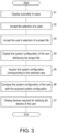
- FIG. 3 is a flowchart showing the flow of a series of processes executed by the system configuration proposal device 1.
- the display part 22 displays a plurality of cases on the display 12 (step S1). Specifically, the display part 22 reads a plurality of case IDs stored in the case DB 32 and case information associated with these case IDs. Then, each read case information is listed and displayed.
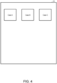
- FIG. 4 is a diagram showing the display 12 on which three cases A to C are displayed.
- the display part 22 displays three cases A to C side by side on the screen of the display 12 as shown in FIG. 4 , for example.
- case A, case B, and case C displayed in FIG. 4 are any of the cases listed above.
- case A is a case of "reducing the frequency of sudden line stoppages due to dirt adhering to the sensor detection surface and the number of times of cleaning."
- Cases B and C are other cases.
- case A, case B, and case C are illustrated in a simplified manner for convenience of explanation, but on the actual screen, text explaining the actual case is displayed as case information.
- case A For example, at the display position of case A, the text of "reducing the frequency of sudden line stoppages due to dirt adhering to the sensor detection surface and the number of times of cleaning" explaining case A, and an image or icon representing case A are displayed. The user views these text and image and selects any case corresponding to the desires of the user.
- step S2 the user operates the input device 11 to select case A displayed on the display 12.
- the input part 21 accepts the selection of case A performed by the user by detecting this operation (step S2).
- step S3 the user operates the input device 11 to select the project file corresponding to the configuration of the PLC system currently owned by the user.
- step S3 accepts the user's selection of the project file by detecting this operation.
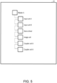
- FIG. 5 is a diagram showing the display 12 on which the existing system configuration of the user defined by the project file is displayed.
- the input part 21 notifies the display part 22 that the project file has been selected.
- the display part 22 reads the selected project file from the user DB 31.
- the display part 22 displays the existing system configuration of the user defined by the read project file on the display 12 as shown in FIG. 5 .
- a plurality of devices included in the system configuration of the user are defined in the project file.
- the master A, the input unit A, the input unit B, the servo driver, the image unit, the coupler unit A, and the coupler unit B are defined in the selected project file. These are all devices included in the system configuration defined by the project file.
- the master A is a controller (control device) of the PLC.
- the input unit A, the input unit B, the servo driver, the image unit, the coupler unit A, and the coupler unit B are all slaves of the PLC controlled by the master A.
- the display part 22 displays the master A and each slave on the display 12 in association with each other as shown in FIG. 5 . In FIG.
- the master A is displayed at the relatively uppermost position, and the input unit A, the input unit B, the servo driver, the image unit, the coupler unit A, and the coupler unit B are respectively displayed below the master A in this order.
- the user grasps the details of the system configuration defined by the selected project file.
- the comparison part 23 acquires the system configuration corresponding to the selected case A from the case DB 32 (step S5).
- the acquisition procedure is as follows.
- the display part 22 notifies the comparison part 23 of the case ID representing the selected case A.
- the comparison part 23 acquires an arbitrary system configuration stored in the case DB 32 in association with the notified case ID.
- the system configurations A1 and A2 corresponding to case A only the system configuration A1 is acquired.
- the comparison part 23 compares the existing system configuration with the acquired system configuration A1 (step S6). Specifically, the comparison part 23 sequentially compares whether the master A and the input unit X included in the system configuration A1 match each device such as the input unit A included in the existing system configuration.
- the existing system configuration includes the master A as shown in FIG. 5 . Thus, the comparison part 23 identifies that the master A required for realizing case A is already included in the existing system configuration of the user. In addition, all the slaves included in the existing system configuration are slaves different from the input unit X. Thus, the comparison part 23 identifies that the input unit X required for realizing case A is not included in the existing system configuration of the user. The comparison part 23 notifies the display part 22 of these identification results.
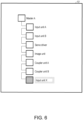
- FIG. 6 is a diagram showing the display 12 on which the devices required for realizing the desires of the user are displayed.
- the display part 22 displays on the display 12 the input unit X that is newly required for realizing the desires of the user (case A) (step S7).
- the display part 22 associates the input unit X with the system configuration of the user and displays these at once.
- the display part 22 displays the input unit X in a state of being connected to the terminal slave in the system configuration of the user.
- the terminal slave is the coupler unit B as shown in FIG. 5 .
- the display part 22 displays the input unit X on the display 12 so as to be connected to the coupler unit B and arranged downstream of the coupler unit B as shown in FIG. 6 . Since the master A included in the system configuration A1 is already included in the existing system configuration, the display part 22 directly displays the existing master A without proposing addition of the master A to the user.
- the user By viewing the new system configuration in which the input unit X is additionally displayed as shown in FIG. 6 , the user is able to grasp the overall image of the new system configuration capable of realizing case A that the user desires. Furthermore, the user is able to grasp that it is possible to realize case A by adding the input unit X to the existing system configuration of the user.
- the display part 22 displays by visually distinguishing the input unit X to be added to the existing system configuration of the user from the devices already included in the system configuration.
- the display part 22 makes the display color of the input unit X different from the display color of the input unit A, etc.
- the user is able to easily grasp that the device to be added for realizing case A is the input unit X.
- the user can select the displayed input unit X by operating the input device 11.
- the input part 21 incorporates the selected input unit X into the existing system configuration of the user.
- the input unit X is additionally saved in the project file in the user DB 31.
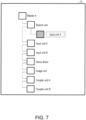
- FIG. 7 is a diagram showing the display 12 on which the devices required for realizing the desires of the user are displayed.
- the display part 22 may display the input unit X required for realizing the desires of the user on the display 12 as shown in FIG. 6 .
- the display part 22 displays the input unit X in a state of being added to another system different from the existing slave system in the system configuration of the user.
- the display part 22 displays on the display 12 a branch unit connected directly under the master A and the input unit X connected to the branch unit.
- the display of the connection destination of the input unit X is changed so that the connection destination of the input unit A is changed from the master A to the branch unit.
- the display part 22 displays by visually distinguishing the input unit X to be added to the existing system configuration of the user from each device already included in the system configuration.
- the display part 22 makes the display color of the input unit X different from the display color of the input unit A, etc.
- the display color of the branch unit is the same as the display color of the input unit A, etc.
- the display part 22 may also make the display color of the branch unit different from the display color of the input unit A, etc., as for the input unit X.
- the system configuration proposal device 1 proposes to the user a new system configuration for devices realizing the desires of the user (that is, case A) based on the existing system configuration of the user.
- the system configuration proposal device 1 proposes to the user a new system configuration for devices realizing the desires of the user (that is, case A) based on the existing system configuration of the user.
- the user who accepts such a proposal does not need to design a new system configuration for realizing case A by himself/herself. There is no need for the user to consider by himself/herself what devices should be added to the existing system configuration of the user to construct a new system configuration that realizes case A.
- the system configuration proposal device 1 is capable of reducing the burden on the user when constructing a new system configuration for realizing the desires of the user.
- the display part 22 may display the performance and specifications of the input unit X to be added together with the input unit X on the display 12 when proposing a system including the additional input unit X to the user.
- the display part 22 may further display on the display 12 the cost of the additional input unit X included in the system proposed to the user together with the input unit X.
- the display part 22 may display on the display 12 the sum of the costs of the plurality of slaves to be added together with the plurality of slaves to be added.
- the comparison part 23 may acquire the system configuration A2 corresponding to case A from the case DB 32. In this case, the comparison part 23 compares the master A included in the system configuration of the user with the master B included in the system configuration A1 corresponding to case A. At this time, it is assumed that the performance of the master B is higher than the performance of the master A. Thus, the comparison part 23 identifies that the performance of the master B is higher than the performance of the master A. The comparison part 23 further identifies that the input unit Y required for realizing case A is not included in the existing system configuration of the user. The comparison part 23 notifies the display part 22 of these identification results.
- the display part 22 receives this notification and displays both the master B and the input unit Y on the display 12, thereby proposing both the master B and the input unit Y to the user.
- the user receives this proposal and grasps that it is possible to construct a PLC system that realizes case A by replacing the existing master A with the new master B and adding the input unit Y.
- the display part 22 may display on the display 12 the sum of the cost of the master B and the cost of the input unit Y together with the master B and the input unit Y.
- case A corresponds to both the system configuration A1 and the system configuration A2. That is, case A is realized by both the system configuration A1 and the system configuration A2.
- the display part 22 may display the input unit X included in the system configuration A1 and the master B and the input unit Y included in the system configuration A2 on the display 12 at once. This can give the user an opportunity to consider whether to select the input unit X or the master B and the unit Y.
- the user is allowed to consider various conditions such as the cost and performance of each unit or the performance and cost of the master B, and select more preferable devices as appropriate.
- the display part 22 may propose a system configuration including minimum devices among a plurality of system configurations corresponding to the selected case. For example, it is assumed that the user selects case B.
- the comparison part 23 can acquire the system configuration B1 or B2 corresponding to case B from the case DB 32. The comparison part 23 first acquires the system configuration B1, and compares each device included in the system configuration B1 with each device included in the existing system configuration of the user. Thereby, the comparison part 23 identifies that neither the master X nor the slave X included in the system configuration B1 is included in the existing system configuration.
- the comparison part 23 acquires the system configuration B2 from the case DB 32 and compares each device included in the system configuration B2 with each device included in the existing system configuration of the user. Thereby, the comparison part 23 identifies that none of the master X, the slave Y, and the slave Z included in the system configuration B2 is included in the existing system configuration.
- the comparison part 23 identifies that the devices required for realizing the selected case B are not included in the existing system configuration of the user. Thus, the comparison part 23 notifies the display part 22 of the system configuration B1, which has the smallest number of devices included in the system configuration, among the system configurations B1 and B2 corresponding to case B.
- the display part 22 receives this notification and proposes the master X and the slave X included in the system configuration B1 to the user. Thereby, the user is able to select the minimum devices required for realizing case B, and therefore is able to construct a new system that realizes case B at the minimum cost.
- the user may input a control cycle required for the master included in the new system configuration that realizes case A. For example, 125 ⁇ s, 500 ⁇ s, or 2 ms is input.
- the input part 21 accepts this input operation and notifies the comparison part 23 of the same.
- the comparison part 23 acquires from the case DB 32 a system configuration corresponding to case A and including a master that is operable with a control cycle equal to or less than the selected control cycle.
- the display part 22 proposes the acquired system configuration to the user. For example, it is assumed that the master B is capable of operating with a control cycle of 200 ⁇ s or less. Also, it is assumed that the user has selected case A and input 500 ⁇ s.
- the comparison part 23 acquires from the case DB 32 the system configuration A2 including the master B that is capable of operating with 500 ⁇ s or less and corresponding to case A.
- the display part 22 displays on the display 12 the master B and the input unit Y included in the system configuration A2.
- the system configuration proposal device 1 is capable of proposing to the user the master B that satisfies the control cycle desired by the user.
- the display part 22 can further propose to the user to add function blocks in the master A included in the system configuration.
- the candidate function blocks to be added may be displayed together with the input unit X on the display 12.
- the user is able to operate the input device 11 to select a device (servo, inverter, robot, etc.) that the user wishes to use in the proposed system configuration.
- a device servo, inverter, robot, etc.
- the display part 22 appropriately changes the system configuration proposed to the user according to the selection result of the user. For example, when servo is selected, the system configuration corresponding to servo may be displayed on the display 12.
- the system configuration proposal device 1 may further include a communication part (not shown) that communicates with an external server.
- the communication part may acquire a web page including cases A to C from the server.
- the display part 22 displays cases A to C on the display 12 by displaying the acquired web page on the display 12.
- the communication part notifies the server that case A has been selected.
- the server receives this notification and transmits the case ID representing case A to the system configuration proposal device 1.
- the communication part receives the transmitted case ID and outputs the same to the comparison part 23.
- the comparison part 23 acquires the system configuration A1 or the system configuration A2 corresponding to the case ID of the input case A from the case DB 32.
- Each functional block of the system configuration proposal device 1 may be implemented by a logic circuit (hardware) formed in an integrated circuit (IC chip) or the like, or may be implemented by software.
- control device includes a computer that executes instructions of a program, which is software that implements each function.
- This computer includes, for example, one or more processors, and includes a computer-readable recording medium storing the program. Then, in the computer, the processor reads the program from the recording medium and executes the program, thereby achieving the object of the present invention.
- a CPU Central Processing Unit
- a recording medium a "non-transitory tangible medium” such as a ROM (Read Only Memory), a tape, a disk, a card, a semiconductor memory, and a programmable logic circuit can be used.
- a RAM Random Access Memory
- the program may be supplied to the computer via any transmission medium (communication network, broadcast wave, etc.) capable of transmitting the program.
- One aspect of the present invention can also be implemented in the form of a data signal embedded in a carrier wave in which the program is embodied by electronic transmission.
- a system configuration proposal device includes: an input part accepting selection of a user for a case; a comparison part comparing an existing system configuration of the user including a PLC (Programmable Logic Controller) with a system configuration corresponding to the case selected; and a proposal part proposing to the user a new system configuration including a device required for realizing the case based on a comparison result.
- PLC Programmable Logic Controller
- a new system configuration including the device for realizing the case is proposed to the user based on the comparison result between the existing system configuration of the user including the PLC and the system configuration corresponding to the case selected by the user. That is, a new system configuration that takes advantage of the existing system of the user is proposed to the user as a system configuration that is capable of realizing the case.
- the user who receives such a proposal does not need to design a new system configuration for realizing the case by himself/herself. There is no need for the user to consider by himself/herself what device should be added to the existing system configuration of the user to construct a new system configuration that realizes the case.
- the system configuration proposal device is capable of reducing the burden on the user when constructing a new system configuration for realizing the desires of the user.
- the proposal part proposes to the user the device that is included in the system configuration corresponding to the case and not included in the existing system configuration.
- the proposal part displays the existing system configuration and the device required for realizing the case in association with each other on a screen.
- the user is allowed to grasp the overall image of the new system configuration capable of realizing the case that the user desires.
- the proposal part displays by visually distinguishing each device included in the existing system configuration for realizing the case from the device required for realizing the case.
- the user is able to easily grasp which device should be added to realize the case.
- a system configuration proposal method includes: an inputting step of accepting selection of a user for a case; a comparing step of comparing an existing system configuration of the user including a PLC (Programmable Logic Controller) with a system configuration corresponding to the case selected; and a proposing step of proposing to the user a new system configuration including a device required for realizing the case based on a comparison result.
- PLC Programmable Logic Controller
Landscapes
- Business, Economics & Management (AREA)
- Engineering & Computer Science (AREA)
- Human Resources & Organizations (AREA)
- General Physics & Mathematics (AREA)
- Physics & Mathematics (AREA)
- Strategic Management (AREA)
- Entrepreneurship & Innovation (AREA)
- Economics (AREA)
- General Business, Economics & Management (AREA)
- Tourism & Hospitality (AREA)
- Marketing (AREA)
- Theoretical Computer Science (AREA)
- Automation & Control Theory (AREA)
- Operations Research (AREA)
- Quality & Reliability (AREA)
- Health & Medical Sciences (AREA)
- Data Mining & Analysis (AREA)
- Manufacturing & Machinery (AREA)
- Primary Health Care (AREA)
- Development Economics (AREA)
- Educational Administration (AREA)
- Game Theory and Decision Science (AREA)
- General Health & Medical Sciences (AREA)
- Programmable Controllers (AREA)
- Management, Administration, Business Operations System, And Electronic Commerce (AREA)
Abstract
Description
- The present invention relates to a system configuration proposal device and a system configuration proposal method.
- In the field of factory automation (FA), various types of devices are controlled to share work processes. In order to operate various controllers, remote I/O, and manufacturing devices used for work in certain areas such as factory facilities in cooperation, industrial network systems, also called field networks, have been constructed to connect these devices.
- A general industrial network system uses a master-slave network composed of various slave devices and a master device. The slave device is a device that controls equipment installed in a factory or collects data. The master device is a device called (PLC: Programmable Logic Controller), for example, that centrally manages these slaves.
- Conventionally, techniques have been proposed for supporting users of industrial network systems. For example,
Patent Literature 1 discloses a design support device for a network system composed of a master device and a plurality of slave devices. The design support device is characterized in including a design information storage means for storing design information including at least slave device information and topology information in a designed network system created by a user; an actual configuration information generation means for generating actual configuration information including at least slave device information and topology information in an actual network system based on the information collected by the master device from each slave device in the actual network system; a comparison means for comparing the design information and the actual configuration information; and an output means for generating a comparison screen showing the configuration of the designed network system and the configuration of the actual network system together with their similarities and differences based on a comparison result of the comparison means, and outputting the comparison screen to a display device. - Furthermore,
Patent Literature 2 discloses a control system including a PLC and an information processing device. The PLC includes an interface unit that functions as an interface with an external device, and a CPU unit that controls the interface unit. The interface unit includes a relay element having a contact point between an internal circuit and the external device, and a third storage part that stores unit identification information for identifying the interface unit. The CPU unit includes a first storage part; a processor that counts the number of times the contact point of the relay element is opened and closed, and stores opening/closing count information representing the number of times of opening and closing in the first storage part; and a transmission part that transmits the opening/closing count information stored in the first storage part to the information processing device, acquires the unit identification information from the interface unit, and transmits the unit identification information to the information processing device. The information processing device includes a second storage part that stores PLC identification information that identifies the PLC, a program to be executed by the PLC, and a generation rule of proposal information representing a proposal for arranging the interface unit; a receiving part that receives the opening/closing count information and the unit identification information; a display part; and a control part that stores the opening/closing count information and the unit identification information received by the receiving part in the second storage part in association with the PLC identification information, analyzes the program to calculate a predicted value of the number of times of opening and closing, generates the proposal information according to the generation rule based on the calculated predicted value, and causes the display part to display the generated proposal information. -
- [Patent Literature 1]
Japanese Patent Laid-Open No. 2012-194631 - [Patent Literature 2]
Japanese Patent No. 6732146 - However, even if the user uses these conventional techniques, it is not possible to support the design of a new system configuration that is able to realize the desires of the user. Thus, it is not possible to reduce the burden on the user when constructing a new system configuration for realizing the desires of the user.
- The present invention has been made in order to solve the above problem, and an object of the present invention is to reduce the burden on the user when constructing a new system configuration for realizing the desires of the user.
- In order to solve the above problem, a system configuration proposal device according to one aspect of the present invention includes: an input part accepting selection of a user for a case; a comparison part comparing an existing system configuration of the user including a PLC (Programmable Logic Controller) with a system configuration corresponding to the case selected; and a proposal part proposing to the user a new system configuration including a device required for realizing the case based on a comparison result.
- One aspect of the present invention achieves an effect that it is possible to reduce the burden on the user when constructing a new system configuration for realizing the desires of the user.
-
-
FIG. 1 is a block diagram showing a configuration of the system configuration proposal device according to an embodiment of the present invention. -
FIG. 2 is a diagram showing an example of the information stored in the case DB. -
FIG. 3 is a flowchart showing the flow of a series of processes executed by the system configuration proposal device. -
FIG. 4 is a diagram showing the display on which three cases are displayed. -
FIG. 5 is a diagram showing the display on which the system configuration of the user defined by the project file is displayed. -
FIG. 6 is a diagram showing the display on which the devices required for realizing the desires of the user are displayed. -
FIG. 7 is a diagram showing the display on which the devices required for realizing the desires of the user are displayed. - Hereinafter, an embodiment (hereinafter also referred to as "this embodiment") according to one aspect of the present invention will be described based on the drawings.
- First, an example of a scene to which the present invention is applied will be described. A system
configuration proposal device 1 shown inFIG. 1 is used by a user to propose a system configuration including a PLC (Programmable Logic Controller) to the user. The user already has an existing PLC system and desires to do something new with use of some PLC system. The systemconfiguration proposal device 1 presents to the user cases corresponding to such desires of the user. - When accepting selection of the user for a case, the system
configuration proposal device 1 compares the existing system configuration of the user with the system configuration corresponding to the accepted case. Then, based on the comparison result, the systemconfiguration proposal device 1 proposes to the user a new system configuration including the devices required for realizing the case. For example, the devices that can obtain a new system configuration which is capable of realizing the case, if added to the existing system configuration of the user, are identified, and addition of such devices to the existing system configuration of the user is proposed to the user. In this way, a new system configuration that takes advantage of the existing system configuration of the user is proposed to the user, so it is possible to reduce the user's time and effort when constructing a new system configuration for realizing the desires of the user. - The system
configuration proposal device 1 according to the embodiment will be described in further detail usingFIG. 1. FIG. 1 is a block diagram showing a configuration of the systemconfiguration proposal device 1 according to an embodiment of the present invention. The systemconfiguration proposal device 1 is a device that proposes to the user a PLC system for realizing the desires of the user. As shown inFIG. 1 , the systemconfiguration proposal device 1 includes acontrol part 10, adisplay 12, aninput device 11, and arecording device 13. Thecontrol part 10 includes a display part 22 (proposal part), aninput part 21, and acomparison part 23. - The
control part 10 comprehensively controls various processes in the systemconfiguration proposal device 1. Theinput device 11 is a device such as a mouse, a keyboard, and a touch panel, through which an operation of the user is input to the systemconfiguration proposal device 1. Thedisplay 12 is a device that displays information on a screen, such as a liquid crystal display and an organic EL display. Therecording device 13 is a device that stores various types of data (information) required for the systemconfiguration proposal device 1 to execute processes. In this embodiment, a user database (user DB) 31 and a case database (case DB) 32 are formed in therecording device 13. - The
input part 21 accepts an operation of the user input to theinput device 11. Thedisplay part 22 controls display of information on thedisplay 12. Details of thecomparison part 23 will be described later. - The
user DB 31 stores a project file of the user. The project file is a file that defines the configuration (system configuration) of the PLC system owned by the user. The project file includes information of each device included in the system configuration of the user and a user program for operating each device. The devices include, for example, a master (controller) and slaves of the PLC. The project file includes information of the master and information of at least one slave controlled by the master. -
FIG. 2 is a diagram showing an example of the information stored in thecase DB 32. Thecase DB 32 stores information related to various cases in the PLC system. The case refers to an example of the desires of the user with use of some PLC system. The cases include, for example, the following: - monitoring the power consumption of the devices and equipment,
- reducing the frequency of sudden line stoppages due to dirt adhering to the sensor detection surface and the number of times of cleaning,
- avoiding the screw troubles and space issues in the low-voltage switch of the three-connection induction motor,
- detecting the existence of a workpiece in the index table,
- reducing the man-hours for wiring due to push-in plus terminal block type terminal relay,
- constantly monitoring the deodorizing fan motor of the scrubber (steam gas processing equipment),
- constantly monitoring the bearing of the cooling water circulation pump,
- constantly monitoring packing deterioration of the homogenizer sliding part,
- reducing the man-hours for fiber unit selection,
- reducing false detection of electronic components in a narrow space in the device,
- preventing foreign matter contamination when detecting the passage of coffee stick (food and beverage products), and
- stably detecting background (base) and color marks (registration marks) with subtle color differences.
- In the example of
FIG. 2 , thecase DB 32 stores information related to case A, information related to case B, and information related to case C. Case A is actually "reducing the frequency of sudden line stoppages due to dirt adhering to the sensor detection surface and the number of times of cleaning." Case B is another case different from case A. Case C is another case different from cases A and B. - The
case DB 32 stores a plurality of case IDs individually representing a plurality of cases. In the example ofFIG. 2 , three case IDs respectively representing case A, case B, and case C are stored in thecase DB 32. Case A, case B, and case C shown inFIG. 2 respectively correspond to the case ID representing case A, the case ID representing case B, and the case ID representing case C. - The
case DB 32 further stores, for each case, the system configuration information required for realizing the corresponding case in association with the case ID. In the example ofFIG. 2 , information of the system configuration A1 and information of the system configuration A2 are stored in thecase DB 32 in association with the case ID of case A. Furthermore, information of the system configuration B1 and information of the system configuration B2 are stored in thecase DB 32 in association with the case ID of case B. Furthermore, information of the system configuration C1 is stored in thecase DB 32 in association with the case ID of case C. - The
system configurations A 1 and A2 are both system configurations required for realizing case A. The system configuration A1 includes the master A and the input unit X, and the system configuration A2 includes the master B and the input unit X. The masters A and B are both masters required for realizing case A. The masters A and B are masters different from each other in terms of performance, specifications, cost, etc., but there is no difference for use to realize case A. The input unit X is a slave required for realizing case A. - Each system configuration is the minimum configuration required for realizing the corresponding case. For example, the system configuration A1 corresponding to case A includes the minimum master A and input unit X required for realizing case A. This means that case A can be realized with the minimum system configuration A1 including the master A and the input unit X.
- Case A, that is, a case of "reducing the frequency of sudden line stoppages due to dirt adhering to the sensor detection surface and the number of times of cleaning," is solved by using a certain photoelectric sensor in the PLC system. This photoelectric sensor is called a photoelectric sensor X hereinafter. The photoelectric sensor X has a connector of a specific shape. Further, since the photoelectric sensor X is a device having a sensing function, the photoelectric sensor X needs to be connected to a slave having an input terminal. Thus, in order to use the photoelectric sensor X in some PLC system, a slave having a connector of a specific shape for inserting the photoelectric sensor X and an input terminal is required. Since the input unit X is a slave that satisfies this condition, the input unit X is a kind of slave required for realizing case A.
- The system configurations B1 and B2 are both system configurations required for realizing case B. The system configuration B1 includes the master X and the slave X, and the system configuration B2 includes the master Y, the slave Y, and the slave Z. The masters X and Y are both masters required for realizing case B. The masters X and Y are masters different from each other in terms of performance, specifications, cost, etc., but there is no difference in that the masters X and Y are masters required for realizing case B. The slaves X, Y, and Z are all slaves required for realizing case B. The slaves X, Y, and Z are slaves different from one another in terms of performance, specifications, cost, etc., but there is no difference in that the slaves X, Y, and Z are slaves required for realizing case B. The slaves Y and Z are slaves that are capable of realizing case B only when both are present.
- The system configuration C1 is a system configuration required for realizing case C. The system configuration C1 includes the master Z and the slave Z. The master Z is a slave required for realizing case C. The slave Z is a slave required for realizing case C.
-
FIG. 3 is a flowchart showing the flow of a series of processes executed by the systemconfiguration proposal device 1. In the systemconfiguration proposal device 1, thedisplay part 22 displays a plurality of cases on the display 12 (step S1). Specifically, thedisplay part 22 reads a plurality of case IDs stored in thecase DB 32 and case information associated with these case IDs. Then, each read case information is listed and displayed. -
FIG. 4 is a diagram showing thedisplay 12 on which three cases A to C are displayed. Thedisplay part 22 displays three cases A to C side by side on the screen of thedisplay 12 as shown inFIG. 4 , for example. It is assumed that case A, case B, and case C displayed inFIG. 4 are any of the cases listed above. For example, case A is a case of "reducing the frequency of sudden line stoppages due to dirt adhering to the sensor detection surface and the number of times of cleaning." Cases B and C are other cases. InFIG. 4 , case A, case B, and case C are illustrated in a simplified manner for convenience of explanation, but on the actual screen, text explaining the actual case is displayed as case information. For example, at the display position of case A, the text of "reducing the frequency of sudden line stoppages due to dirt adhering to the sensor detection surface and the number of times of cleaning" explaining case A, and an image or icon representing case A are displayed. The user views these text and image and selects any case corresponding to the desires of the user. - Here, it is assumed that what the user desires is case A. The user operates the
input device 11 to select case A displayed on thedisplay 12. Theinput part 21 accepts the selection of case A performed by the user by detecting this operation (step S2). Next, the user operates theinput device 11 to select the project file corresponding to the configuration of the PLC system currently owned by the user. Theinput part 21 accepts the user's selection of the project file by detecting this operation (step S3). -
FIG. 5 is a diagram showing thedisplay 12 on which the existing system configuration of the user defined by the project file is displayed. Theinput part 21 notifies thedisplay part 22 that the project file has been selected. Thedisplay part 22 reads the selected project file from theuser DB 31. Thedisplay part 22 displays the existing system configuration of the user defined by the read project file on thedisplay 12 as shown inFIG. 5 . - A plurality of devices included in the system configuration of the user are defined in the project file. Here, the master A, the input unit A, the input unit B, the servo driver, the image unit, the coupler unit A, and the coupler unit B are defined in the selected project file. These are all devices included in the system configuration defined by the project file. The master A is a controller (control device) of the PLC. The input unit A, the input unit B, the servo driver, the image unit, the coupler unit A, and the coupler unit B are all slaves of the PLC controlled by the master A. The
display part 22 displays the master A and each slave on thedisplay 12 in association with each other as shown inFIG. 5 . InFIG. 5 , the master A is displayed at the relatively uppermost position, and the input unit A, the input unit B, the servo driver, the image unit, the coupler unit A, and the coupler unit B are respectively displayed below the master A in this order. By viewing the screen shown inFIG. 5 , the user grasps the details of the system configuration defined by the selected project file. - Next, the
comparison part 23 acquires the system configuration corresponding to the selected case A from the case DB 32 (step S5). The acquisition procedure is as follows. Thedisplay part 22 notifies thecomparison part 23 of the case ID representing the selected case A. Thecomparison part 23 acquires an arbitrary system configuration stored in thecase DB 32 in association with the notified case ID. Here, among the system configurations A1 and A2 corresponding to case A, only the system configuration A1 is acquired. - The
comparison part 23 compares the existing system configuration with the acquired system configuration A1 (step S6). Specifically, thecomparison part 23 sequentially compares whether the master A and the input unit X included in the system configuration A1 match each device such as the input unit A included in the existing system configuration. The existing system configuration includes the master A as shown inFIG. 5 . Thus, thecomparison part 23 identifies that the master A required for realizing case A is already included in the existing system configuration of the user. In addition, all the slaves included in the existing system configuration are slaves different from the input unit X. Thus, thecomparison part 23 identifies that the input unit X required for realizing case A is not included in the existing system configuration of the user. Thecomparison part 23 notifies thedisplay part 22 of these identification results. -
FIG. 6 is a diagram showing thedisplay 12 on which the devices required for realizing the desires of the user are displayed. As shown inFIG. 6 , thedisplay part 22 displays on thedisplay 12 the input unit X that is newly required for realizing the desires of the user (case A) (step S7). This proposes a new system configuration including the input unit X to the user. At this time, thedisplay part 22 associates the input unit X with the system configuration of the user and displays these at once. In the example ofFIG. 6 , thedisplay part 22 displays the input unit X in a state of being connected to the terminal slave in the system configuration of the user. The terminal slave is the coupler unit B as shown inFIG. 5 . Therefore, thedisplay part 22 displays the input unit X on thedisplay 12 so as to be connected to the coupler unit B and arranged downstream of the coupler unit B as shown inFIG. 6 . Since the master A included in the system configuration A1 is already included in the existing system configuration, thedisplay part 22 directly displays the existing master A without proposing addition of the master A to the user. - By viewing the new system configuration in which the input unit X is additionally displayed as shown in
FIG. 6 , the user is able to grasp the overall image of the new system configuration capable of realizing case A that the user desires. Furthermore, the user is able to grasp that it is possible to realize case A by adding the input unit X to the existing system configuration of the user. - The
display part 22 displays by visually distinguishing the input unit X to be added to the existing system configuration of the user from the devices already included in the system configuration. InFIG. 6 , thedisplay part 22 makes the display color of the input unit X different from the display color of the input unit A, etc. By viewing the screen of thedisplay 12 shown inFIG. 6 , the user is able to easily grasp that the device to be added for realizing case A is the input unit X. - The user can select the displayed input unit X by operating the
input device 11. When detecting this operation, theinput part 21 incorporates the selected input unit X into the existing system configuration of the user. Specifically, the input unit X is additionally saved in the project file in theuser DB 31. -
FIG. 7 is a diagram showing thedisplay 12 on which the devices required for realizing the desires of the user are displayed. Thedisplay part 22 may display the input unit X required for realizing the desires of the user on thedisplay 12 as shown inFIG. 6 . In the example ofFIG. 7 , thedisplay part 22 displays the input unit X in a state of being added to another system different from the existing slave system in the system configuration of the user. Specifically, thedisplay part 22 displays on the display 12 a branch unit connected directly under the master A and the input unit X connected to the branch unit. Furthermore, the display of the connection destination of the input unit X is changed so that the connection destination of the input unit A is changed from the master A to the branch unit. By viewing the new system configuration in which the input unit X is additionally displayed as shown inFIG. 7 , the user is able to grasp that it is possible to realize case A by adding the branch unit and the input unit X to the existing system configuration of the user. - In the example of
FIG. 7 , thedisplay part 22 displays by visually distinguishing the input unit X to be added to the existing system configuration of the user from each device already included in the system configuration. InFIG. 7 , thedisplay part 22 makes the display color of the input unit X different from the display color of the input unit A, etc. The display color of the branch unit is the same as the display color of the input unit A, etc. However, thedisplay part 22 may also make the display color of the branch unit different from the display color of the input unit A, etc., as for the input unit X. By viewing the screen of thedisplay 12 shown inFIG. 7 , the user is able to easily grasp that the device to be added for realizing case A is the input unit X. - According to this embodiment, the system
configuration proposal device 1 proposes to the user a new system configuration for devices realizing the desires of the user (that is, case A) based on the existing system configuration of the user. Thus, it is possible to make a proposal that takes advantage of the existing system configuration of the user. The user who accepts such a proposal does not need to design a new system configuration for realizing case A by himself/herself. There is no need for the user to consider by himself/herself what devices should be added to the existing system configuration of the user to construct a new system configuration that realizes case A. In this way, the systemconfiguration proposal device 1 is capable of reducing the burden on the user when constructing a new system configuration for realizing the desires of the user. - The
display part 22 may display the performance and specifications of the input unit X to be added together with the input unit X on thedisplay 12 when proposing a system including the additional input unit X to the user. - The
display part 22 may further display on thedisplay 12 the cost of the additional input unit X included in the system proposed to the user together with the input unit X. When proposing a system including a plurality of additional slaves to the user, thedisplay part 22 may display on thedisplay 12 the sum of the costs of the plurality of slaves to be added together with the plurality of slaves to be added. - When case A is selected, the
comparison part 23 may acquire the system configuration A2 corresponding to case A from thecase DB 32. In this case, thecomparison part 23 compares the master A included in the system configuration of the user with the master B included in the system configuration A1 corresponding to case A. At this time, it is assumed that the performance of the master B is higher than the performance of the master A. Thus, thecomparison part 23 identifies that the performance of the master B is higher than the performance of the master A. Thecomparison part 23 further identifies that the input unit Y required for realizing case A is not included in the existing system configuration of the user. Thecomparison part 23 notifies thedisplay part 22 of these identification results. - The
display part 22 receives this notification and displays both the master B and the input unit Y on thedisplay 12, thereby proposing both the master B and the input unit Y to the user. The user receives this proposal and grasps that it is possible to construct a PLC system that realizes case A by replacing the existing master A with the new master B and adding the input unit Y. - When proposing both the master B and the input unit Y to the user, the
display part 22 may display on thedisplay 12 the sum of the cost of the master B and the cost of the input unit Y together with the master B and the input unit Y. - When a plurality of different system configurations correspond to the case selected by the user, the
display part 22 may display these system configurations at once. For example, in the example ofFIG. 3 , case A corresponds to both the system configuration A1 and the system configuration A2. That is, case A is realized by both the system configuration A1 and the system configuration A2. Thus, when the user selects case A, thedisplay part 22 may display the input unit X included in the system configuration A1 and the master B and the input unit Y included in the system configuration A2 on thedisplay 12 at once. This can give the user an opportunity to consider whether to select the input unit X or the master B and the unit Y. The user is allowed to consider various conditions such as the cost and performance of each unit or the performance and cost of the master B, and select more preferable devices as appropriate. - If the device required for realizing the selected case is not included in the existing system configuration of the user, the
display part 22 may propose a system configuration including minimum devices among a plurality of system configurations corresponding to the selected case. For example, it is assumed that the user selects case B. In this case, thecomparison part 23 can acquire the system configuration B1 or B2 corresponding to case B from thecase DB 32. Thecomparison part 23 first acquires the system configuration B1, and compares each device included in the system configuration B1 with each device included in the existing system configuration of the user. Thereby, thecomparison part 23 identifies that neither the master X nor the slave X included in the system configuration B1 is included in the existing system configuration. - Thus, the
comparison part 23 then acquires the system configuration B2 from thecase DB 32 and compares each device included in the system configuration B2 with each device included in the existing system configuration of the user. Thereby, thecomparison part 23 identifies that none of the master X, the slave Y, and the slave Z included in the system configuration B2 is included in the existing system configuration. - Based on these identification results, the
comparison part 23 identifies that the devices required for realizing the selected case B are not included in the existing system configuration of the user. Thus, thecomparison part 23 notifies thedisplay part 22 of the system configuration B1, which has the smallest number of devices included in the system configuration, among the system configurations B1 and B2 corresponding to case B. Thedisplay part 22 receives this notification and proposes the master X and the slave X included in the system configuration B1 to the user. Thereby, the user is able to select the minimum devices required for realizing case B, and therefore is able to construct a new system that realizes case B at the minimum cost. - After selecting case A, the user may input a control cycle required for the master included in the new system configuration that realizes case A. For example, 125 µs, 500 µs, or 2 ms is input. The
input part 21 accepts this input operation and notifies thecomparison part 23 of the same. Thecomparison part 23 acquires from the case DB 32 a system configuration corresponding to case A and including a master that is operable with a control cycle equal to or less than the selected control cycle. Thedisplay part 22 proposes the acquired system configuration to the user. For example, it is assumed that the master B is capable of operating with a control cycle of 200 µs or less. Also, it is assumed that the user has selected case A and input 500 µs. In this case, thecomparison part 23 acquires from thecase DB 32 the system configuration A2 including the master B that is capable of operating with 500 µs or less and corresponding to case A. Thedisplay part 22 displays on thedisplay 12 the master B and the input unit Y included in the system configuration A2. Thereby, the systemconfiguration proposal device 1 is capable of proposing to the user the master B that satisfies the control cycle desired by the user. - When proposing a new system configuration including the additional input unit X to the user, the
display part 22 can further propose to the user to add function blocks in the master A included in the system configuration. For example, the candidate function blocks to be added may be displayed together with the input unit X on thedisplay 12. - The user is able to operate the
input device 11 to select a device (servo, inverter, robot, etc.) that the user wishes to use in the proposed system configuration. When theinput part 21 accepts this operation, thedisplay part 22 appropriately changes the system configuration proposed to the user according to the selection result of the user. For example, when servo is selected, the system configuration corresponding to servo may be displayed on thedisplay 12. - The system
configuration proposal device 1 may further include a communication part (not shown) that communicates with an external server. The communication part may acquire a web page including cases A to C from the server. In this case, thedisplay part 22 displays cases A to C on thedisplay 12 by displaying the acquired web page on thedisplay 12. For example, when case A is selected by the user through the displayed web page, the communication part notifies the server that case A has been selected. The server receives this notification and transmits the case ID representing case A to the systemconfiguration proposal device 1. The communication part receives the transmitted case ID and outputs the same to thecomparison part 23. Thecomparison part 23 acquires the system configuration A1 or the system configuration A2 corresponding to the case ID of the input case A from thecase DB 32. - Each functional block of the system configuration proposal device 1 (in particular, the
input part 21, thedisplay part 22, and the comparison part 23) may be implemented by a logic circuit (hardware) formed in an integrated circuit (IC chip) or the like, or may be implemented by software. - In the latter case, the control device includes a computer that executes instructions of a program, which is software that implements each function. This computer includes, for example, one or more processors, and includes a computer-readable recording medium storing the program. Then, in the computer, the processor reads the program from the recording medium and executes the program, thereby achieving the object of the present invention.
- As the processor, for example, a CPU (Central Processing Unit) can be used. As the recording medium, a "non-transitory tangible medium" such as a ROM (Read Only Memory), a tape, a disk, a card, a semiconductor memory, and a programmable logic circuit can be used.
- In addition, a RAM (Random Access Memory) for expanding the program may be further provided. Furthermore, the program may be supplied to the computer via any transmission medium (communication network, broadcast wave, etc.) capable of transmitting the program. One aspect of the present invention can also be implemented in the form of a data signal embedded in a carrier wave in which the program is embodied by electronic transmission.
- A system configuration proposal device according to one aspect of the present invention includes: an input part accepting selection of a user for a case; a comparison part comparing an existing system configuration of the user including a PLC (Programmable Logic Controller) with a system configuration corresponding to the case selected; and a proposal part proposing to the user a new system configuration including a device required for realizing the case based on a comparison result.
- According to the above configuration, a new system configuration including the device for realizing the case is proposed to the user based on the comparison result between the existing system configuration of the user including the PLC and the system configuration corresponding to the case selected by the user. That is, a new system configuration that takes advantage of the existing system of the user is proposed to the user as a system configuration that is capable of realizing the case. The user who receives such a proposal does not need to design a new system configuration for realizing the case by himself/herself. There is no need for the user to consider by himself/herself what device should be added to the existing system configuration of the user to construct a new system configuration that realizes the case. In this way, the system configuration proposal device is capable of reducing the burden on the user when constructing a new system configuration for realizing the desires of the user.
- In an embodiment, the proposal part proposes to the user the device that is included in the system configuration corresponding to the case and not included in the existing system configuration.
- According to the above configuration, it is possible to appropriately propose to the user the device required for realizing the case that the user desires.
- In an embodiment, the proposal part displays the existing system configuration and the device required for realizing the case in association with each other on a screen.
- According to the above configuration, the user is allowed to grasp the overall image of the new system configuration capable of realizing the case that the user desires.
- In an embodiment, the proposal part displays by visually distinguishing each device included in the existing system configuration for realizing the case from the device required for realizing the case.
- According to the above configuration, the user is able to easily grasp which device should be added to realize the case.
- A system configuration proposal method according to one aspect of the present invention includes: an inputting step of accepting selection of a user for a case; a comparing step of comparing an existing system configuration of the user including a PLC (Programmable Logic Controller) with a system configuration corresponding to the case selected; and a proposing step of proposing to the user a new system configuration including a device required for realizing the case based on a comparison result.
- According to the above configuration, it is possible to reduce the burden on the user when constructing a new system configuration for realizing the desires of the user.
- The present invention is not limited to the embodiments described above, and various modifications are possible within the scope defined by the claims. Embodiments obtained by appropriately combining the technical means disclosed in different embodiments are also included in the technical scope of the present invention. New technical features can also be formed by combining the technical means disclosed in the embodiments.
-
- 1 system configuration proposal device
- 10 control part
- 11 input device
- 12 display
- 13 recording device
- 21 input part
- 22 display part
- 23 comparison part
- 31 user DB
- 32 case DB
Claims (5)
- A system configuration proposal device, comprising:an input part accepting selection of a user for a case;a comparison part comparing an existing system configuration of the user including a PLC (Programmable Logic Controller) with a system configuration corresponding to the case selected; anda proposal part proposing to the user a new system configuration including a device required for realizing the case based on a comparison result.
- The system configuration proposal device according to claim 1, wherein the proposal part proposes to the user the device that is included in the system configuration corresponding to the case and not included in the existing system configuration.
- The system configuration proposal device according to claim 1 or 2, wherein the proposal part displays the existing system configuration and the device required for realizing the case in association with each other on a screen.
- The system configuration proposal device according to claim 3, wherein the proposal part displays by visually distinguishing each device included in the existing system configuration from the device required for realizing the case.
- A system configuration proposal method, comprising:an inputting step of accepting selection of a user for a case;a comparing step of comparing an existing system configuration of the user including a PLC (Programmable Logic Controller) with a system configuration corresponding to the case selected; anda proposing step of proposing to the user a new system configuration including a device required for realizing the case based on a comparison result.
Applications Claiming Priority (2)
| Application Number | Priority Date | Filing Date | Title |
|---|---|---|---|
| JP2021008292A JP7600705B2 (en) | 2021-01-21 | 2021-01-21 | System configuration proposal device and system configuration proposal method |
| PCT/JP2021/007925 WO2022157989A1 (en) | 2021-01-21 | 2021-03-02 | System configuration proposal device and system configuration proposal method |
Publications (2)
| Publication Number | Publication Date |
|---|---|
| EP4283417A1 true EP4283417A1 (en) | 2023-11-29 |
| EP4283417A4 EP4283417A4 (en) | 2025-01-01 |
Family
ID=82548627
Family Applications (1)
| Application Number | Title | Priority Date | Filing Date |
|---|---|---|---|
| EP21921096.0A Pending EP4283417A4 (en) | 2021-01-21 | 2021-03-02 | SYSTEM CONFIGURATION PROPOSAL DEVICE AND SYSTEM CONFIGURATION PROPOSAL METHOD |
Country Status (5)
| Country | Link |
|---|---|
| US (1) | US20240019835A1 (en) |
| EP (1) | EP4283417A4 (en) |
| JP (1) | JP7600705B2 (en) |
| CN (1) | CN116547687A (en) |
| WO (1) | WO2022157989A1 (en) |
Families Citing this family (1)
| Publication number | Priority date | Publication date | Assignee | Title |
|---|---|---|---|---|
| CN118625819B (en) * | 2024-08-14 | 2024-10-18 | 泰山学院 | Mobile robot mixed obstacle avoidance control method based on switch signals |
Family Cites Families (11)
| Publication number | Priority date | Publication date | Assignee | Title |
|---|---|---|---|---|
| JPS5983752A (en) | 1982-11-02 | 1984-05-15 | Furukawa Electric Co Ltd:The | Preparation of heat resistant aluminum alloy conductor |
| JPH11231927A (en) * | 1998-02-17 | 1999-08-27 | Toshiba Corp | Monitoring and control system |
| JP2003005978A (en) * | 2001-05-02 | 2003-01-10 | Ge Fanuc Automation North America Inc | Power managing and controlling system, method for adding device to the same system and computer for generating screen for the same device |
| JP2003114937A (en) * | 2001-10-03 | 2003-04-18 | Fujitsu Ltd | Sales commission adjustment method and computer program |
| JP3709984B2 (en) * | 2001-10-16 | 2005-10-26 | 横河電機株式会社 | Fieldbus system construction equipment |
| JP3827092B2 (en) * | 2003-10-22 | 2006-09-27 | オムロン株式会社 | Control system setting device, control system setting method, and setting program |
| CN101303584B (en) * | 2008-06-26 | 2010-08-25 | 上海交通大学 | Method for reconfiguring control module of reconfigurable digital controller |
| JP5120473B2 (en) * | 2011-03-15 | 2013-01-16 | オムロン株式会社 | Network system design support device |
| JP6058238B2 (en) * | 2015-01-22 | 2017-01-11 | 三菱電機株式会社 | Programmable logic controller setting file generation support device |
| CN109254842B (en) * | 2017-07-12 | 2023-06-16 | 腾讯科技(深圳)有限公司 | Resource management method and device for distributed stream system and readable storage medium |
| CN108388495A (en) * | 2018-01-10 | 2018-08-10 | 链家网(北京)科技有限公司 | A kind of data monitoring method and system |
-
2021
- 2021-01-21 JP JP2021008292A patent/JP7600705B2/en active Active
- 2021-03-02 US US18/268,306 patent/US20240019835A1/en active Pending
- 2021-03-02 CN CN202180081679.XA patent/CN116547687A/en active Pending
- 2021-03-02 EP EP21921096.0A patent/EP4283417A4/en active Pending
- 2021-03-02 WO PCT/JP2021/007925 patent/WO2022157989A1/en not_active Ceased
Also Published As
| Publication number | Publication date |
|---|---|
| WO2022157989A1 (en) | 2022-07-28 |
| JP7600705B2 (en) | 2024-12-17 |
| EP4283417A4 (en) | 2025-01-01 |
| US20240019835A1 (en) | 2024-01-18 |
| CN116547687A (en) | 2023-08-04 |
| JP2022112427A (en) | 2022-08-02 |
Similar Documents
| Publication | Publication Date | Title |
|---|---|---|
| CN102405448B (en) | Operator terminal in Process Control System | |
| US9043716B2 (en) | Methods and apparatus to create process control graphics based on process control information | |
| CN102404138A (en) | Method for computer-aided analysis of automation equipment | |
| US10375152B2 (en) | Data capture on a serial device | |
| CN106843193A (en) | Method and device for showing process control equipment information | |
| JP6852519B2 (en) | Program creation support device, control method of program creation support device, and control program of program creation support device | |
| CN101620508A (en) | Graphical user interface | |
| CN113811823A (en) | Dependencies between process objects | |
| RU178497U1 (en) | CONTROLLER FOR MANAGING THE INDUSTRIAL OBJECTS MONITORING SYSTEM | |
| EP4283417A1 (en) | System configuration proposal device and system configuration proposal method | |
| US20040059440A1 (en) | System for automating, monitoring and controlling technical processes and acquiring measurements thereof | |
| US10606239B2 (en) | Shaping plant and safety program | |
| US20030200004A1 (en) | System for automation of technical processes | |
| JP2014035687A (en) | Engineering system and monitoring control method thereof | |
| WO2021145138A1 (en) | Display device, display method, and display program | |
| CN118076930A (en) | Control system for a technical facility with a zoomed-out view of the facility image | |
| GB2564250A (en) | Interlock chain visualization | |
| Kotikangas | Utilization of digital twin for customer tailored variable speed drive | |
| CN117321524A (en) | Control system of technical installations with trend curve diagram | |
| US7103444B1 (en) | Method and apparatus for supervising manufacturing tools | |
| EP3859220A1 (en) | Heat source system management apparatus, management system, and method for displaying heat source system management information | |
| EP3779615A1 (en) | Abnormality detection device, abnormality detection method, and abnormality detection program | |
| EP3579071A1 (en) | Information processing device, control method for information processing device, and control program | |
| KR101578557B1 (en) | Relay monitoring device | |
| JP2012079203A (en) | Monitoring control system |
Legal Events
| Date | Code | Title | Description |
|---|---|---|---|
| STAA | Information on the status of an ep patent application or granted ep patent |
Free format text: STATUS: THE INTERNATIONAL PUBLICATION HAS BEEN MADE |
|
| PUAI | Public reference made under article 153(3) epc to a published international application that has entered the european phase |
Free format text: ORIGINAL CODE: 0009012 |
|
| STAA | Information on the status of an ep patent application or granted ep patent |
Free format text: STATUS: REQUEST FOR EXAMINATION WAS MADE |
|
| 17P | Request for examination filed |
Effective date: 20230607 |
|
| AK | Designated contracting states |
Kind code of ref document: A1 Designated state(s): AL AT BE BG CH CY CZ DE DK EE ES FI FR GB GR HR HU IE IS IT LI LT LU LV MC MK MT NL NO PL PT RO RS SE SI SK SM TR |
|
| DAV | Request for validation of the european patent (deleted) | ||
| DAX | Request for extension of the european patent (deleted) | ||
| A4 | Supplementary search report drawn up and despatched |
Effective date: 20241129 |
|
| RIC1 | Information provided on ipc code assigned before grant |
Ipc: G06F 30/10 20200101ALI20241125BHEP Ipc: G06Q 50/04 20120101ALI20241125BHEP Ipc: G05B 19/05 20060101AFI20241125BHEP |