EP4283384A1 - A backlight unit for a motor vehicle display apparatus integrated with a heat transfer device and method thereof - Google Patents
A backlight unit for a motor vehicle display apparatus integrated with a heat transfer device and method thereof Download PDFInfo
- Publication number
- EP4283384A1 EP4283384A1 EP23158119.0A EP23158119A EP4283384A1 EP 4283384 A1 EP4283384 A1 EP 4283384A1 EP 23158119 A EP23158119 A EP 23158119A EP 4283384 A1 EP4283384 A1 EP 4283384A1
- Authority
- EP
- European Patent Office
- Prior art keywords
- capillary tube
- heat transfer
- motor vehicle
- vehicle display
- display apparatus
- Prior art date
- Legal status (The legal status is an assumption and is not a legal conclusion. Google has not performed a legal analysis and makes no representation as to the accuracy of the status listed.)
- Granted
Links
Images




Classifications
-
- G—PHYSICS
- G02—OPTICS
- G02B—OPTICAL ELEMENTS, SYSTEMS OR APPARATUS
- G02B6/00—Light guides; Structural details of arrangements comprising light guides and other optical elements, e.g. couplings
- G02B6/0001—Light guides; Structural details of arrangements comprising light guides and other optical elements, e.g. couplings specially adapted for lighting devices or systems
- G02B6/0011—Light guides; Structural details of arrangements comprising light guides and other optical elements, e.g. couplings specially adapted for lighting devices or systems the light guides being planar or of plate-like form
- G02B6/0081—Mechanical or electrical aspects of the light guide and light source in the lighting device peculiar to the adaptation to planar light guides, e.g. concerning packaging
- G02B6/0085—Means for removing heat created by the light source from the package
-
- B—PERFORMING OPERATIONS; TRANSPORTING
- B60—VEHICLES IN GENERAL
- B60K—ARRANGEMENT OR MOUNTING OF PROPULSION UNITS OR OF TRANSMISSIONS IN VEHICLES; ARRANGEMENT OR MOUNTING OF PLURAL DIVERSE PRIME-MOVERS IN VEHICLES; AUXILIARY DRIVES FOR VEHICLES; INSTRUMENTATION OR DASHBOARDS FOR VEHICLES; ARRANGEMENTS IN CONNECTION WITH COOLING, AIR INTAKE, GAS EXHAUST OR FUEL SUPPLY OF PROPULSION UNITS IN VEHICLES
- B60K35/00—Instruments specially adapted for vehicles; Arrangement of instruments in or on vehicles
-
- G—PHYSICS
- G02—OPTICS
- G02F—OPTICAL DEVICES OR ARRANGEMENTS FOR THE CONTROL OF LIGHT BY MODIFICATION OF THE OPTICAL PROPERTIES OF THE MEDIA OF THE ELEMENTS INVOLVED THEREIN; NON-LINEAR OPTICS; FREQUENCY-CHANGING OF LIGHT; OPTICAL LOGIC ELEMENTS; OPTICAL ANALOGUE/DIGITAL CONVERTERS
- G02F1/00—Devices or arrangements for the control of the intensity, colour, phase, polarisation or direction of light arriving from an independent light source, e.g. switching, gating or modulating; Non-linear optics
- G02F1/01—Devices or arrangements for the control of the intensity, colour, phase, polarisation or direction of light arriving from an independent light source, e.g. switching, gating or modulating; Non-linear optics for the control of the intensity, phase, polarisation or colour
- G02F1/13—Devices or arrangements for the control of the intensity, colour, phase, polarisation or direction of light arriving from an independent light source, e.g. switching, gating or modulating; Non-linear optics for the control of the intensity, phase, polarisation or colour based on liquid crystals, e.g. single liquid crystal display cells
- G02F1/133—Constructional arrangements; Operation of liquid crystal cells; Circuit arrangements
- G02F1/1333—Constructional arrangements; Manufacturing methods
- G02F1/1335—Structural association of cells with optical devices, e.g. polarisers or reflectors
- G02F1/1336—Illuminating devices
- G02F1/133628—Illuminating devices with cooling means
-
- B—PERFORMING OPERATIONS; TRANSPORTING
- B60—VEHICLES IN GENERAL
- B60K—ARRANGEMENT OR MOUNTING OF PROPULSION UNITS OR OF TRANSMISSIONS IN VEHICLES; ARRANGEMENT OR MOUNTING OF PLURAL DIVERSE PRIME-MOVERS IN VEHICLES; AUXILIARY DRIVES FOR VEHICLES; INSTRUMENTATION OR DASHBOARDS FOR VEHICLES; ARRANGEMENTS IN CONNECTION WITH COOLING, AIR INTAKE, GAS EXHAUST OR FUEL SUPPLY OF PROPULSION UNITS IN VEHICLES
- B60K35/00—Instruments specially adapted for vehicles; Arrangement of instruments in or on vehicles
- B60K35/20—Output arrangements, i.e. from vehicle to user, associated with vehicle functions or specially adapted therefor
- B60K35/21—Output arrangements, i.e. from vehicle to user, associated with vehicle functions or specially adapted therefor using visual output, e.g. blinking lights or matrix displays
- B60K35/22—Display screens
-
- B—PERFORMING OPERATIONS; TRANSPORTING
- B60—VEHICLES IN GENERAL
- B60K—ARRANGEMENT OR MOUNTING OF PROPULSION UNITS OR OF TRANSMISSIONS IN VEHICLES; ARRANGEMENT OR MOUNTING OF PLURAL DIVERSE PRIME-MOVERS IN VEHICLES; AUXILIARY DRIVES FOR VEHICLES; INSTRUMENTATION OR DASHBOARDS FOR VEHICLES; ARRANGEMENTS IN CONNECTION WITH COOLING, AIR INTAKE, GAS EXHAUST OR FUEL SUPPLY OF PROPULSION UNITS IN VEHICLES
- B60K35/00—Instruments specially adapted for vehicles; Arrangement of instruments in or on vehicles
- B60K35/60—Instruments characterised by their location or relative disposition in or on vehicles
-
- B—PERFORMING OPERATIONS; TRANSPORTING
- B60—VEHICLES IN GENERAL
- B60K—ARRANGEMENT OR MOUNTING OF PROPULSION UNITS OR OF TRANSMISSIONS IN VEHICLES; ARRANGEMENT OR MOUNTING OF PLURAL DIVERSE PRIME-MOVERS IN VEHICLES; AUXILIARY DRIVES FOR VEHICLES; INSTRUMENTATION OR DASHBOARDS FOR VEHICLES; ARRANGEMENTS IN CONNECTION WITH COOLING, AIR INTAKE, GAS EXHAUST OR FUEL SUPPLY OF PROPULSION UNITS IN VEHICLES
- B60K37/00—Dashboards
-
- G—PHYSICS
- G02—OPTICS
- G02B—OPTICAL ELEMENTS, SYSTEMS OR APPARATUS
- G02B6/00—Light guides; Structural details of arrangements comprising light guides and other optical elements, e.g. couplings
- G02B6/0001—Light guides; Structural details of arrangements comprising light guides and other optical elements, e.g. couplings specially adapted for lighting devices or systems
- G02B6/0011—Light guides; Structural details of arrangements comprising light guides and other optical elements, e.g. couplings specially adapted for lighting devices or systems the light guides being planar or of plate-like form
- G02B6/0081—Mechanical or electrical aspects of the light guide and light source in the lighting device peculiar to the adaptation to planar light guides, e.g. concerning packaging
- G02B6/0086—Positioning aspects
- G02B6/0088—Positioning aspects of the light guide or other optical sheets in the package
-
- H—ELECTRICITY
- H05—ELECTRIC TECHNIQUES NOT OTHERWISE PROVIDED FOR
- H05K—PRINTED CIRCUITS; CASINGS OR CONSTRUCTIONAL DETAILS OF ELECTRIC APPARATUS; MANUFACTURE OF ASSEMBLAGES OF ELECTRICAL COMPONENTS
- H05K7/00—Constructional details common to different types of electric apparatus
- H05K7/20—Modifications to facilitate cooling, ventilating, or heating
- H05K7/20954—Modifications to facilitate cooling, ventilating, or heating for display panels
- H05K7/2099—Liquid coolant with phase change
-
- B—PERFORMING OPERATIONS; TRANSPORTING
- B60—VEHICLES IN GENERAL
- B60K—ARRANGEMENT OR MOUNTING OF PROPULSION UNITS OR OF TRANSMISSIONS IN VEHICLES; ARRANGEMENT OR MOUNTING OF PLURAL DIVERSE PRIME-MOVERS IN VEHICLES; AUXILIARY DRIVES FOR VEHICLES; INSTRUMENTATION OR DASHBOARDS FOR VEHICLES; ARRANGEMENTS IN CONNECTION WITH COOLING, AIR INTAKE, GAS EXHAUST OR FUEL SUPPLY OF PROPULSION UNITS IN VEHICLES
- B60K2360/00—Indexing scheme associated with groups B60K35/00 or B60K37/00 relating to details of instruments or dashboards
- B60K2360/20—Optical features of instruments
- B60K2360/33—Illumination features
-
- G—PHYSICS
- G02—OPTICS
- G02F—OPTICAL DEVICES OR ARRANGEMENTS FOR THE CONTROL OF LIGHT BY MODIFICATION OF THE OPTICAL PROPERTIES OF THE MEDIA OF THE ELEMENTS INVOLVED THEREIN; NON-LINEAR OPTICS; FREQUENCY-CHANGING OF LIGHT; OPTICAL LOGIC ELEMENTS; OPTICAL ANALOGUE/DIGITAL CONVERTERS
- G02F1/00—Devices or arrangements for the control of the intensity, colour, phase, polarisation or direction of light arriving from an independent light source, e.g. switching, gating or modulating; Non-linear optics
- G02F1/01—Devices or arrangements for the control of the intensity, colour, phase, polarisation or direction of light arriving from an independent light source, e.g. switching, gating or modulating; Non-linear optics for the control of the intensity, phase, polarisation or colour
- G02F1/13—Devices or arrangements for the control of the intensity, colour, phase, polarisation or direction of light arriving from an independent light source, e.g. switching, gating or modulating; Non-linear optics for the control of the intensity, phase, polarisation or colour based on liquid crystals, e.g. single liquid crystal display cells
- G02F1/133—Constructional arrangements; Operation of liquid crystal cells; Circuit arrangements
- G02F1/1333—Constructional arrangements; Manufacturing methods
- G02F1/1335—Structural association of cells with optical devices, e.g. polarisers or reflectors
- G02F1/1336—Illuminating devices
- G02F1/133615—Edge-illuminating devices, i.e. illuminating from the side
Definitions
- the backlight unit is a single piece of electronic component integrated with a heat transfer device, suitable for use in a motor vehicle display apparatus.
- Display apparatus is commonly used in automotive industry for displaying vehicular information.
- a display apparatus includes an illumination source to transmit light rays towards a viewer, such that information displayed can be viewed on the displays screen.
- the illumination source In operation, the illumination source generates heat and only 40% of electrical power is converted to light rays. The remaining 60% of electrical power is dissipated as heat.
- temperature of an operating display apparatus has an ambient temperature of 85°C. Therefore, efficient thermal management to avoid overheating of display systems is crucial.
- the illumination source is positioned directly behind a display layer and thermal management to dissipate heat spread out on a heated surface of the illumination source by radiation and convention through air.
- One commonly known method is to use a housing with good thermal conductivity properties.
- materials with good thermal conductivity properties such as aluminum or magnesium alloy makes the display apparatus heavy and expensive.
- a purpose of this disclosure is to ameliorate the problem of overheating of motor vehicle display apparatus by providing the subject-matter of the independent claims.
- an edge-lit motor vehicle display apparatus comprising a backlight unit (600) integrated with at least one heat transfer device (100), the at least one heat transfer device (100) comprising:
- An advantage of the above described aspect of this disclosure yields a heat transfer device for integrating with a backlight unit of a motor vehicle display apparatus, of which the heat transfer device contains a phase changing medium capable of fluidly transferring between two capillary tubes during a heat transfer process.
- the heat transfer device disclosed herein utilises two forms of heat transfer methods. Firstly, the walls of the heat transfer device transfer heat by conduction. Secondly, the phase changing medium transfer heat by convection. Consequently, heat dissipation efficiency is improved due to the amount of heat transfer and the rate of heat transfer achieved by the heat transfer device disclosed.
- the edge-lit motor vehicle display apparatus as described above or as described above as being preferred, in which: the anterior capillary tube and the posterior capillary tube are connected by a C-shape connector, thereby forming a U-shape heat transfer device having a gap between the anterior capillary tube and the posterior capillary tube.
- the advantage of the above aspect of this disclosure is to yield a single piece of U-shape heat transfer device with a first capillary tube, i.e. the anterior capillary tube functioning to dissipate heat from a heat source, such a hot surface of a display apparatus and a second capillary tube, i.e. the posterior capillary tube functioning to dissipate heat at a distance from the heat source.
- a first capillary tube i.e. the anterior capillary tube functioning to dissipate heat from a heat source, such a hot surface of a display apparatus
- a second capillary tube i.e. the posterior capillary tube functioning to dissipate heat at a distance from the heat source.
- the aforesaid configuration provides an environment to allow a temperature difference between the anterior capillary tube and the posterior capillary tube, such that the phase changing mediums is operable to evaporate in a first capillary tube and condenses in a second capillary tube during
- the edge-lit motor vehicle display apparatus as described above or as described above as being preferred, in which: the C-shape connector has a bending radius of at least three times a diameter of the heat transfer device.
- the advantage of the above aspect of this disclosure is to achieve connecting the anterior capillary tube and the posterior capillary tube without any sharp and abrupt edges such that a fluid transfer of the phase changing medium between the anterior capillary tube and the posterior capillary tube during heat transfer process is achieved.
- the edge-lit motor vehicle display apparatus as described above or as described above as being preferred, in which: the gap between the anterior capillary tube and the posterior capillary tube is at least 5mm.
- the advantage of the above aspect of this disclosure is to yield a difference between the anterior capillary tube and the posterior capillary tube, to provide an environment to allow a temperature difference between the anterior capillary tube and the posterior capillary tube, such that the phase changing mediums is operable to convert to a gaseous state in a first capillary tube and condenses in a second capillary tube during a heat transfer process.
- a 5mm gap allows a temperature difference desired.
- the edge-lit motor vehicle display apparatus as described above or as described above as being preferred, in which: the anterior capillary tube has a length of at least 150mm.
- the advantage of the above aspect of this disclosure is to yield a U-shape heat transfer device configuration which relatively short, such that the U-shape heat transfer device does not lose heat dissipation efficiency.
- the edge-lit motor vehicle display apparatus as described above or as described above as being preferred, in which: the posterior capillary tube is at least partially positioned within a heat sink.
- the advantage of the above aspect of this disclosure is to allow heat to be conducted by a heat sink from the posterior capillary tube and dissipated into the surrounding air in response to the phase changing medium being fluidly transferred to the posterior capillary tube.
- the advantage of the above aspect of this disclosure is to provide a heat dissipation by convection through the use of a phase changing medium, to remove heat from a hot surface of a motor vehicle display apparatus when in operation.
- the edge-lit motor vehicle display apparatus as described above or as described above as being preferred, in which: during the heat transfer process, in response to the phase changing medium being fluidly transferred to the posterior capillary tube, the phase changing medium condenses to the liquid state within the posterior capillary tube when latent heat is released from the phase changing medium.
- the advantage of the above aspect of this disclosure is to provide a heat dissipation by convection, such that latent heat is released when the phase changing medium condenses to a liquid state.
- the anterior capillary tube further comprises a T-shape bar.
- the advantage of the above aspect of this disclosure is to provide a means for integrating the heat transfer device with another electronic component.
- the edge-lit motor vehicle display apparatus as described above or as described above as being preferred, in which: the posterior capillary tube has a length shorter than the anterior capillary tube.
- the advantage of the above aspect of this disclosure is to accommodate changes in volume of the phase changing medium during convection to increase efficiency of heat dissipation.
- the objective of this disclosure is solved by a method to produce an edge-lit motor vehicle display apparatus according to of the aspects as disclosed herein, comprising integration of an anterior capillary tube and a posterior capillary tube on a rear side of a backlight unit of an edge-lit motor vehicle display apparatus.
- the advantage of the above aspect of this disclosure is to provide a backlight unit integrated with a heat transfer device, that is suitable for edge-lit display apparatus and more in particular, motor vehicle display apparatus.
- An advantage of the above described aspect of this disclosure yields an backlight unit integrated with a heat transfer device which addresses the challenges of heat dissipation efficiency and selection of material used for housing of a motor vehicle display as discussed above.
- the objective of this disclosure is solved by a method of assembling a heat transfer assembly for integrating with a backlight unit for a motor vehicle display, the method comprising:
- An advantage of the above described aspect of this disclosure yields a method of assembling a single piece of U-shape heat transfer device having a first capillary tube, i.e. the anterior capillary tube functioning to dissipate heat from a heat source, such a hot surface of a display apparatus and a second capillary tube, i.e. the posterior capillary tube functioning to dissipate heat at a distance from the heat source.
- the two capillary tubes are connected by a C-shape connector, which provides a smooth, curved channel to allow a phase changing medium to fluidly transfer between the first capillary tube and the second capillary tube.
- the aforesaid configuration provides an environment to allow a temperature difference between the anterior capillary tube and the posterior capillary tube, such that the phase changing mediums is operable to change into a gaseous state in a first capillary tube and condenses in a second capillary tube during a heat transfer process.
- the advantage of the above aspect of this disclosure is to provide a heat transfer device with a phase changing medium contained within the heat transfer device, for heat dissipation by convection.
- Preferred is the method of assembling a heat transfer assembly for integrating with a backlight unit as described above or as described above as being preferred, in which the method further comprises:
- the advantage of the above aspect of this disclosure is to provide a means to rapidly dissipate heat from the second capillary tube or the posterior capillary tube to the surrounding air when the heat transfer device is integrated in a backlight unit.
- the advantage of the above aspect of this disclosure is to include a step of attaching the first capillary tube to a T-shape bar, to provide a means to integrate the heat transfer device assembled with a backlight unit.
- the objective of this disclosure is solved by a method of assembling an edge-light motor vehicle display apparatus for use in a motor vehicle, the method comprising:
- An advantage of the above described aspect of this disclosure yields a method of assembling a motor vehicle display apparatus having a rear-side housing integrated with a heat transfer device as disclosed herein.
- Preferred is a method of assembling an edge-light motor vehicle display apparatus for use in a motor vehicle, as described above or as described above as being preferred, in which: the at least a portion of the at least one heat transfer device is a T-shape bar attached to the heat transfer device.
- the advantage of the above aspect of this disclosure is to provide a means for integrating the heat transfer device with the motor vehicle display apparatus.
- Preferred is a method of assembling an edge-light motor vehicle display apparatus for use in a motor vehicle as described above or as described above as being preferred, in which the method further comprises: adhering an array of light emitting diode (LED) along a length of the T-shape bar.
- LED light emitting diode
- the advantage of the above aspect of this disclosure is to include a step in the assembling process to produce an illumination source using a portion of the heat transfer device.
- the advantage of the above aspect of this disclosure is to include a step in the assembling process to include a light conductor, such that the light conductor is operable to receive light rays from the array of LED, to transmit light rays towards a viewing area of the motor vehicle display apparatus.
- LED light emitting diode
- the advantage of the above aspect of this disclosure is to include a step in the assembling process to yield a backlight unit integrated with a heat transfer device as disclosed herein, where the backlight unit is suitable for use as an illumination source of an edge-lit motor vehicle display.
- the heat transfer device comprising a phase changing medium to dissipate heat from a hot surface using convection.
- the heat transfer device may be assembled to integrate with a backlight unit of an edge-lit motor vehicle display apparatus.
- motor vehicle display apparatus shall refer to display apparatus capable of displaying vehicle information, which may include central display of dashboard, a hybrid cluster and digital cluster.
- phase change or “phase changing” used in the context of this disclosure may refer to aggregated phases of materials.
- first, second, third and the like used in the context of this disclosure may refer to modification of different elements in accordance with various exemplary embodiments, but not limited thereto. The expressions may be used to distinguish one element from another element, regardless of sequence of importance.
- a first capillary tube and “a second capillary tube” may indicate different capillary tubes regardless of order or importance.
- a first capillary tube may be referred to as the second capillary tube and vice versa without departing from the scope of this disclosure.
- a first capillary tube may refer to “an anterior capillary tube” and "a second capillary tube” may refer to "a posterior capillary tube” when describing various different exemplary embodiments in this disclosure.
- a first capillary tube or “anterior capillary tube” may refer to a capillary tube positioned nearer to a housing of a motor vehicle display apparatus, or a capillary tube positioned nearer to a backlight unit of a motor vehicle display apparatus as disclosed herein.
- second capillary tube or “posterior capillary tube” may refer to a capillary tube positioned further or at a distance away from a housing of a motor vehicle display apparatus, or a capillary tube positioned further or at a distance away from a backlight unit, for integrating with a motor vehicle display apparatus.
- the heat transfer device 100 comprises a first capillary tube 102 and a second capillary tube 104.
- An end of the first capillary tube 102 is connected to an end of the second capillary tube 104 using a C-shape connector, to yield a U-shape heat transfer device 100 with a gap X therebetween.
- the C-shape connecter is at least three times a diameter of the heat transfer device 100, to provide a smooth, curved channel to allow a phase changing medium (not shown in figures) to fluidly transfer between the first capillary tube 102 and the second capillary tube 104 during convection.
- the gap X between the first capillary tube 102 and the second capillary tube 104 is at least 5mm apart.
- This gap X allows a temperature difference between the first capillary tube or the anterior capillary tube 102 and the second capillary tube or the posterior capillary tube 104, such that the phase changing mediums is operable to change into a gaseous state in a first capillary tube and condenses to a liquid state in a second capillary tube during a heat transfer process.
- the phase changing medium is added to the heat transfer device 100 under almost vacuum condition.
- a suitable type of phase changing medium may be distilled water.
- the phase changing medium may changes into a gaseous state very quickly at an operational temperature of 30°C or higher.
- the phase changing medium evaporates and converts to a gaseous state within the first capillary tube or anterior capillary tube 102 to dissipate heat from a hot surface.
- the phase changing medium may be fluidly transferred from the first capillary tube or the anterior capillary tube 102 in the gaseous state to the second capillary tube or posterior capillary tube 104 through the C-shape connector 106.
- the aforesaid configuration yields a single heat transfer device 100 which provides two forms of heat transfer method, i.e. dissipation of heat by conduction through walls of the heat transfer device 100, and dissipation of heat by convection through phase changing between evaporation and condensation of the phase changing medium.
- the aforesaid configuration improves heat dissipation efficiency due to the amount of heat being transferred and the rate of heat dissipation for removal of heat from a hot surface by using two forms of heat dissipation methods.
- a main advantage of using a phase changing medium in heat transfer device 100 is to achieve higher thermal conductivity than a solid copper or solid aluminum rod of the same size and shape.
- a solid copper road conducts thermal conductivity at approximately 390 W/m-k while the heat transfer device 100 disclosed may be at least five times higher compared to the thermal conductivity of solid copper rod.
- integrating heat transfer device 100 to a motor vehicle display apparatus addresses eliminates the require of display housing made of heavy and expensive thermal conductive materials.
- FIG. 2 shows an exploded view of a heat transfer assembly 200 in accordance with a preferred embodiment.
- the heat transfer assembly 200 includes at least one heat transfer device 100 as disclosed above, with at least one heat sink 108 having a cavity to at least partially position the second capillary tube or the posterior capillary tube 104 within the heat sink 108.
- the heat sink 108 is to allow heat to be conducted by a heat sink from the posterior capillary tube 104 and dissipated into the surrounding air in response to the phase changing medium being fluidly transferred to the posterior capillary tube 104.
- the heat transfer assembly 200 may further include at least one T-shape bar 110.
- T-shape bar 110 it is possible to use at least two elongated bar of suitable material to form a T-shape bar 110 or simply use a T-shape bar 100 fabricated for such purposes, but not limited thereto.
- the T-shape bar 110, heat transfer device 100 and the heat sink 108 may be assembled or attached together as a single component by way of one or more fasteners, such as screws.
- An advantage of using a T-shape bar 110 is to provide a means to integrate the heat transfer assembly 200 with a motor vehicle display apparatus, which will be further discussed below.
- FIG. 3 is a perspective view of a heat transfer assembly 300 in accordance with a preferred embodiment, which shows the second capillary tube or posterior capillary tube 104 at least partially positioned within a heat sink 108.
- the heat sink 108 shall not cover gap X as shown in FIG. 3 .
- FIG. 4a which shows a rear view 400a of a heat transfer assembly 400a in accordance with a preferred embodiment
- the heat transfer assembly 200, 300 is integrate with a rear-side housing 402 of a motor vehicle display.
- the rear-side housing 402 includes at least one slot 404.
- the at least one slot 404, 404' is operable to receive a portion of the at least one heat transfer assembly 200, 300.
- Preferably a least a portion of the T-shape bar 110 is extended through the at least one slot 404, 404', to achieve integrating the heat transfer assembly with a motor vehicle display apparatus.
- FIG. 4b which illustrates a side view 400b of a heat transfer assembly in accordance with a preferred embodiment
- two heat transfer assembly 200, 300 are integrated with a rear-side housing 402 of a motor vehicle display apparatus, comprising at least two slots 400, 400' for extending the T-shape bar 110, 110' therethrough.
- the rear-side housing 402 may be made of non-thermal conductive material, such as plastic.
- non-thermal conductive material such as plastic.
- FIG. 5 shows a perspective view of an illumination source 500 in accordance with a preferred embodiment.
- a rear-side housing 402 integrated with a heat transfer assembly 200, 300 with at least a portion of the T-shape bar extending through at least one slot provided by the rear-side housing 402.
- An array of light emitting diode (LED) 502 is adhere onto a length of the T-shape bar 110 to yield an illumination source.
- the length is a surface of the T-shape bar 110 extending through the at least one slot provided by the rear-side housing 402.
- heat generated by the illumination source from the illumination source 500 is dissipated by the anterior capillary tube 102 of the heat transfer device 100, causing a phase changing medium in the anterior capillary tube 102 to evaporate and transfer into a gaseous state due to convection.
- the vapor is fluidly transferred to the posterior capillary tube 104, through the C-shape connector 106.
- the phase changing medium in a gaseous state condenses into a liquid state as the heat sink 108 rapidly dissipate heat from the posterior capillary tube 104 to the surrounding, thereby achieving heat dissipation efficiency.
- FIG. 6 shows a perspective view of an edge-lit motor vehicle display apparatus 600 in accordance with a preferred embodiment.
- the T-shape bar 110 from the heat transfer assembly 200, 300 extends through a slot of a rear-side housing 402 of a motor vehicle display, with an array of LED 502 adhered to a length of the T-shape bar 110 to form an illumination source 500.
- the T-shape bar 110 is attached to a U-shape heat transfer device 100 as disclosed herein, with an anterior capillary tube 102 in connect with the T-shape bar 110.
- a light conductor 602 is displaced adjacent to the array of LED 502, such that light rays emitting from the array of LED 502 may be transmitted through the light conductor 602.
- the light conductor 602 may include reflective surface, for example reflective foil adhere to a non-viewing side or rear side of the motor vehicle display apparatus, such that the light rays are reflected and transmitted through a display layer 604, as indicated by the arrows shown in FIG. 6 .
- the motor vehicle apparatus may include a cover 704.
- the light rays emitting from the array of LED 502 is transmitted through the light conductor 602 and reflected through the display layer 604, towards a viewing area 702.
- Suitable types of display layers include liquid crystal display (LCD) layer and thin film transistor (TFT) display layer.
- FIG. 8a shows a rear-view of an edge-lit motor vehicle display apparatus 800a in accordance with a preferred embodiment.
- the heat transfer assembly 200, 303 may be placed long a length of a rear-side housing 402, as disclosed in the exemplary embodiments above.
- the heat transfer assembly 200 may be mounted on a portion of a body of the rear side housing 402 of a motor vehicle display apparatus, where the position of the heat transfer assembly 200, 300 corresponds to a position of the light conductor 602.
- the heat transfer assembly 200, 300 is fastened to the rear side housing 402 using brackets, but not limited thereto. More advantageously, the heat transfer assembly 200, 300 is integrated with the backlight unit of the motor vehicle display apparatus and is operable to dissipate heat from the backlight unit when in operation
- FIG. 8b shows a rear-view of an edge-lit motor vehicle display apparatus 800b in accordance with a preferred embodiment.
- a third heat transfer assembly 200", 300" may be positioned corresponding to other electronic components which may require heat dissipation, with at least two heat sink 108 at least partially enclosing the posteriori capillary tube 104.
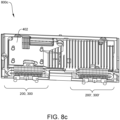
- FIG. 8c shows a rear-view of an edge-lit motor vehicle display apparatus 800c in accordance with a preferred embodiment
- at least two heat assemblies are integrated with a rear side housing 402
- each of the heat transfer assembly comprises at least two heat transfer devices 100.
- Each of the posterior capillary tube 104 is at least partially positioned within a heat sink 108.
- each heat transfer device covers half of a width of the backlight unit, to optimize heat dissipation efficiency.
- aspects of the above embodiments discloses a device, assembly, and method of assembling a heat transfer device 100, a heat transfer assembly 200, 300, method of integrating the heat transfer assembly 200, 300 with a rear-side housing of a motor vehicle display apparatus and utilizing at least a portion of the heat transfer assembly to provide an illumination source of a backlight unit for an edge-lit motor vehicle display apparatus.
- the edge-lit motor vehicle display apparatus comprising a backlight unit integrated with at least one heat transfer device 100 is suitable for mounting onto a compartment of a motor vehicle.
- the heat transfer device as disclosed may be assembled and integrated to a display apparatus, in particular a motor vehicle display apparatus. More specifically, because of the higher thermal conductivity of achievable by the heat transfer device disclosed, conventional motor vehicle display housing made of high thermal conductivity materials may be replaced with plastic housing, thus achieving cost efficiency.
- the heat transfer device may be assembled and integrated with a rear-side housing to produce an illumination source for a backlight unit, thereby yielding thinner or slimmer edge-lit motor vehicle display apparatus, with high heat dissipation rate. While exemplary embodiments have been presented in the foregoing detailed description of the disclosure, it should be appreciated that a vast number of variation exist.
- a heat transfer device 102 A first capillary tube / anterior capillary tube 104 A second capillary tube / posterior capillary tube 106 C-shape connector 200 Heat transfer assembly 108 Heat sink 110 T-shape bar 112, 112', 112" Fasteners 300 A second capillary tube / posterior capillary tube with heat sink 400a Exemplary Embodiment - at least one heat sink assembly 402 Rear-side housing of motor vehicle display apparatus 404, 404' At least one slot 400b Exemplary Embodiment - two heat sink assembly 500 Exemplary Embodiment - illumination source 502 Array of light emitting diode (LED) 600 Exemplary Embodiment - backlight unit integrated with heat sink assembly 602 Light conductor 604 Display layer 700 Exemplary Embodiment - edge-lit display apparatus with backlight 702 Viewing area 704 Cover of motor vehicle display apparatus 800a Exemplary Embodiment - rear-side of display with heat sink assembly 800b Exemplary Embodiment - rear
Landscapes
- Physics & Mathematics (AREA)
- Engineering & Computer Science (AREA)
- Chemical & Material Sciences (AREA)
- Nonlinear Science (AREA)
- Optics & Photonics (AREA)
- General Physics & Mathematics (AREA)
- Combustion & Propulsion (AREA)
- Transportation (AREA)
- Mechanical Engineering (AREA)
- Crystallography & Structural Chemistry (AREA)
- Mathematical Physics (AREA)
- Thermal Sciences (AREA)
- Microelectronics & Electronic Packaging (AREA)
- Devices For Indicating Variable Information By Combining Individual Elements (AREA)
- Instrument Panels (AREA)
- Arrangement Of Elements, Cooling, Sealing, Or The Like Of Lighting Devices (AREA)
Abstract
Description
- This disclosure relates to backlight unit for a motor vehicle display apparatus. In particular, the backlight unit is a single piece of electronic component integrated with a heat transfer device, suitable for use in a motor vehicle display apparatus.
- Display apparatus is commonly used in automotive industry for displaying vehicular information. A display apparatus includes an illumination source to transmit light rays towards a viewer, such that information displayed can be viewed on the displays screen. In operation, the illumination source generates heat and only 40% of electrical power is converted to light rays. The remaining 60% of electrical power is dissipated as heat. In automotive applications, temperature of an operating display apparatus has an ambient temperature of 85°C. Therefore, efficient thermal management to avoid overheating of display systems is crucial.
- Conventionally, the illumination source is positioned directly behind a display layer and thermal management to dissipate heat spread out on a heated surface of the illumination source by radiation and convention through air. One commonly known method is to use a housing with good thermal conductivity properties. However, the drawback of this solution is that materials with good thermal conductivity properties such as aluminum or magnesium alloy makes the display apparatus heavy and expensive.
- There is therefore a need to provide to provide a motor vehicle display apparatus that overcomes, or at least ameliorates, the problems described above. Furthermore, other desirable features and characteristics will become apparent from the subsequent detailed description and the appended claims, taking in conjunction with the accompanying drawings and this background of the disclosure.
- A purpose of this disclosure is to ameliorate the problem of overheating of motor vehicle display apparatus by providing the subject-matter of the independent claims.
- Further purposes of this disclosure are set out in the accompanying dependent claims.
- The objective of this disclosure is solved by an edge-lit motor vehicle display apparatus (700) comprising a backlight unit (600) integrated with at least one heat transfer device (100), the at least one heat transfer device (100) comprising:
- an anterior capillary tube operable to integrate with a rear side of a backlight unit, the anterior capillary tube further operable to dissipate heat from an anterior of a backlight unit of a motor vehicle display apparatus;
- a posterior capillary tube operable to be positioned away from the rear side of the backlight unit, the posterior capillary tube further operable to dissipate heat from a posterior of a backlight unit of a motor vehicle display; and
- a phase changing medium operable to fluidly transfer between the anterior capillary tube and the posterior capillary tube during a heat transfer process,
- An advantage of the above described aspect of this disclosure yields a heat transfer device for integrating with a backlight unit of a motor vehicle display apparatus, of which the heat transfer device contains a phase changing medium capable of fluidly transferring between two capillary tubes during a heat transfer process. More advantageously, the heat transfer device disclosed herein utilises two forms of heat transfer methods. Firstly, the walls of the heat transfer device transfer heat by conduction. Secondly, the phase changing medium transfer heat by convection. Consequently, heat dissipation efficiency is improved due to the amount of heat transfer and the rate of heat transfer achieved by the heat transfer device disclosed.
- Preferred is the edge-lit motor vehicle display apparatus as described above or as described above as being preferred, in which:
the anterior capillary tube and the posterior capillary tube are connected by a C-shape connector, thereby forming a U-shape heat transfer device having a gap between the anterior capillary tube and the posterior capillary tube. - The advantage of the above aspect of this disclosure is to yield a single piece of U-shape heat transfer device with a first capillary tube, i.e. the anterior capillary tube functioning to dissipate heat from a heat source, such a hot surface of a display apparatus and a second capillary tube, i.e. the posterior capillary tube functioning to dissipate heat at a distance from the heat source. Advantageously, the aforesaid configuration provides an environment to allow a temperature difference between the anterior capillary tube and the posterior capillary tube, such that the phase changing mediums is operable to evaporate in a first capillary tube and condenses in a second capillary tube during a heat transfer process.
- Preferred is the edge-lit motor vehicle display apparatus as described above or as described above as being preferred, in which:
the C-shape connector has a bending radius of at least three times a diameter of the heat transfer device. - The advantage of the above aspect of this disclosure is to achieve connecting the anterior capillary tube and the posterior capillary tube without any sharp and abrupt edges such that a fluid transfer of the phase changing medium between the anterior capillary tube and the posterior capillary tube during heat transfer process is achieved.
- Preferred is the edge-lit motor vehicle display apparatus as described above or as described above as being preferred, in which:
the gap between the anterior capillary tube and the posterior capillary tube is at least 5mm. - The advantage of the above aspect of this disclosure is to yield a difference between the anterior capillary tube and the posterior capillary tube, to provide an environment to allow a temperature difference between the anterior capillary tube and the posterior capillary tube, such that the phase changing mediums is operable to convert to a gaseous state in a first capillary tube and condenses in a second capillary tube during a heat transfer process. Preferably, a 5mm gap allows a temperature difference desired.
- Preferred is the edge-lit motor vehicle display apparatus as described above or as described above as being preferred, in which:
the anterior capillary tube has a length of at least 150mm. - The advantage of the above aspect of this disclosure is to yield a U-shape heat transfer device configuration which relatively short, such that the U-shape heat transfer device does not lose heat dissipation efficiency.
- Preferred is the edge-lit motor vehicle display apparatus as described above or as described above as being preferred, in which:
the posterior capillary tube is at least partially positioned within a heat sink. - The advantage of the above aspect of this disclosure is to allow heat to be conducted by a heat sink from the posterior capillary tube and dissipated into the surrounding air in response to the phase changing medium being fluidly transferred to the posterior capillary tube.
- Preferred is the edge-lit motor vehicle display apparatus as described above or as described above as being preferred, in which:
during the heat transfer process, - the phase changing medium evaporate to the gaseous state within the anterior capillary tube to dissipate heat from the anterior of the backlight unit; and
- the phase changing medium is fluidly transferred from the anterior capillary tube in the gaseous state to the posterior capillary tube.
- The advantage of the above aspect of this disclosure is to provide a heat dissipation by convection through the use of a phase changing medium, to remove heat from a hot surface of a motor vehicle display apparatus when in operation.
- Preferred is the edge-lit motor vehicle display apparatus as described above or as described above as being preferred, in which:
during the heat transfer process,
in response to the phase changing medium being fluidly transferred to the posterior capillary tube,
the phase changing medium condenses to the liquid state within the posterior capillary tube when latent heat is released from the phase changing medium. - The advantage of the above aspect of this disclosure is to provide a heat dissipation by convection, such that latent heat is released when the phase changing medium condenses to a liquid state.
- Preferred is the edge-lit motor vehicle display apparatus as described above or as described above as being preferred, in which:
the anterior capillary tube further comprises a T-shape bar. - The advantage of the above aspect of this disclosure is to provide a means for integrating the heat transfer device with another electronic component.
- Preferred is the edge-lit motor vehicle display apparatus as described above or as described above as being preferred, in which:
the posterior capillary tube has a length shorter than the anterior capillary tube. - The advantage of the above aspect of this disclosure is to accommodate changes in volume of the phase changing medium during convection to increase efficiency of heat dissipation.
- The objective of this disclosure is solved by a method to produce an edge-lit motor vehicle display apparatus according to of the aspects as disclosed herein, comprising integration of an anterior capillary tube and a posterior capillary tube on a rear side of a backlight unit of an edge-lit motor vehicle display apparatus.
- The advantage of the above aspect of this disclosure is to provide a backlight unit integrated with a heat transfer device, that is suitable for edge-lit display apparatus and more in particular, motor vehicle display apparatus.
- An advantage of the above described aspect of this disclosure yields an backlight unit integrated with a heat transfer device which addresses the challenges of heat dissipation efficiency and selection of material used for housing of a motor vehicle display as discussed above.
- The objective of this disclosure is solved by a method of assembling a heat transfer assembly for integrating with a backlight unit for a motor vehicle display, the method comprising:
- providing a first capillary tube for dissipating heat from an anterior of a backlight unit of a motor vehicle display;
- providing a second capillary tube for dissipating heat from a posterior of a backlight unit of a motor vehicle display;
- connecting, by way of a C-shape connector, an end of the first capillary tube to an end of the second capillary tube,
- An advantage of the above described aspect of this disclosure yields a method of assembling a single piece of U-shape heat transfer device having a first capillary tube, i.e. the anterior capillary tube functioning to dissipate heat from a heat source, such a hot surface of a display apparatus and a second capillary tube, i.e. the posterior capillary tube functioning to dissipate heat at a distance from the heat source. Advantageously, the two capillary tubes are connected by a C-shape connector, which provides a smooth, curved channel to allow a phase changing medium to fluidly transfer between the first capillary tube and the second capillary tube.
- More advantageously, the aforesaid configuration provides an environment to allow a temperature difference between the anterior capillary tube and the posterior capillary tube, such that the phase changing mediums is operable to change into a gaseous state in a first capillary tube and condenses in a second capillary tube during a heat transfer process.
- Preferred is the method of assembling a heat transfer assembly for integrating with a backlight unit as described above or as described above as being preferred, in which the method further comprises:
filling a phase changing medium within the U-shape heat transfer device under a vacuum condition. - The advantage of the above aspect of this disclosure is to provide a heat transfer device with a phase changing medium contained within the heat transfer device, for heat dissipation by convection.
- Preferred is the method of assembling a heat transfer assembly for integrating with a backlight unit as described above or as described above as being preferred, in which the method further comprises:
- providing a heat sink; and
- at least partially positioning the second capillary tube within the heat sink.
- The advantage of the above aspect of this disclosure is to provide a means to rapidly dissipate heat from the second capillary tube or the posterior capillary tube to the surrounding air when the heat transfer device is integrated in a backlight unit.
- Preferred is the method of assembling a heat transfer assembly for integrating with a backlight unit as described above or as described above as being preferred, in which the method further comprises:
attaching at least a portion of the first capillary tube to a T-shape bar by way of one or more fasteners. - The advantage of the above aspect of this disclosure is to include a step of attaching the first capillary tube to a T-shape bar, to provide a means to integrate the heat transfer device assembled with a backlight unit.
- The objective of this disclosure is solved by a method of assembling an edge-light motor vehicle display apparatus for use in a motor vehicle, the method comprising:
- providing at least one heat transfer device as described above or as described above as being preferred;
- providing a housing for a rear side of a motor vehicle display apparatus, the housing comprises at least one slot; and
- extending at least a portion of the at least one heat transfer device through the at least one slot of the housing, thereby yielding an edge-lit motor vehicle display apparatus integrated with at least one heat transfer device.
- An advantage of the above described aspect of this disclosure yields a method of assembling a motor vehicle display apparatus having a rear-side housing integrated with a heat transfer device as disclosed herein.
- Preferred is a method of assembling an edge-light motor vehicle display apparatus for use in a motor vehicle, as described above or as described above as being preferred, in which:
the at least a portion of the at least one heat transfer device is a T-shape bar attached to the heat transfer device. - The advantage of the above aspect of this disclosure is to provide a means for integrating the heat transfer device with the motor vehicle display apparatus.
- Preferred is a method of assembling an edge-light motor vehicle display apparatus for use in a motor vehicle as described above or as described above as being preferred, in which the method further comprises:
adhering an array of light emitting diode (LED) along a length of the T-shape bar. - The advantage of the above aspect of this disclosure is to include a step in the assembling process to produce an illumination source using a portion of the heat transfer device.
- Preferred is a method of assembling an edge-light motor vehicle display apparatus for use in a motor vehicle as described above or as described above as being preferred, in which the method further comprises:
fixing a light conductor adjacent to T-shape bar, the light conductor for transmitting light rays towards a viewing area of the motor vehicle display apparatus. - The advantage of the above aspect of this disclosure is to include a step in the assembling process to include a light conductor, such that the light conductor is operable to receive light rays from the array of LED, to transmit light rays towards a viewing area of the motor vehicle display apparatus.
- Preferred is a method of assembling an edge-light motor vehicle display apparatus for use in a motor vehicle as described above or as described above as being preferred, in which the method further comprises:
aligning the array of light emitting diode (LED) along the length of the T-shape bar to a length of the light conductor, thereby providing a backlight unit for an edge-lit motor vehicle display. - The advantage of the above aspect of this disclosure is to include a step in the assembling process to yield a backlight unit integrated with a heat transfer device as disclosed herein, where the backlight unit is suitable for use as an illumination source of an edge-lit motor vehicle display.
- Other objects and aspects of this disclosure will become apparent from the following description of embodiments with reference to the accompanying drawings in which:
-
FIG. 1 . shows a heat transfer device in accordance with a preferred embodiment. -
FIG. 2 shows an exploded view of a heat transfer assembly in accordance with a preferred embodiment. -
FIG. 3 shows a perspective view of a heat transfer assembly in accordance with a preferred embodiment. -
FIG. 4a shows a rear view of a heat transfer assembly in accordance with a preferred embodiment. -
FIG. 4b shows a side view of a heat transfer assembly in accordance with a preferred embodiment. -
FIG. 5 shows a perspective view of a backlight unit in accordance with a preferred embodiment. -
FIG. 6 shows a perspective view of an edge-lit motor vehicle display apparatus in accordance with a preferred embodiment. -
FIG. 7 shows a side view of an edge-lit motor vehicle display apparatus in accordance with a preferred embodiment. -
FIG. 8a shows a rear-view of an edge-lit motor vehicle display apparatus in accordance with a preferred embodiment. -
FIG. 8b shows a rear-view of an edge-lit motor vehicle display apparatus in accordance with a preferred embodiment. -
FIG. 8c shows a rear-view of an edge-lit motor vehicle display apparatus in accordance with a preferred embodiment. - In various embodiments described by reference to the above figures, like reference signs refer to like components in several perspective views and/or configurations.
- The following detailed description is merely exemplary in nature and is not intended to limit the disclosure or the application and uses of the disclosure. Furthermore, there is no intention to be bound by any theory presented in the preceding background of the disclosure or the following detailed description. It is the intent of this disclosure to present a heat transfer device comprising a phase changing medium to dissipate heat from a hot surface using convection. In particular, the heat transfer device may be assembled to integrate with a backlight unit of an edge-lit motor vehicle display apparatus.
- Hereinafter, the term "motor vehicle display apparatus" shall refer to display apparatus capable of displaying vehicle information, which may include central display of dashboard, a hybrid cluster and digital cluster.
- The term "phase change" or "phase changing" used in the context of this disclosure may refer to aggregated phases of materials.
- The term "first", "second", "third" and the like used in the context of this disclosure may refer to modification of different elements in accordance with various exemplary embodiments, but not limited thereto. The expressions may be used to distinguish one element from another element, regardless of sequence of importance. By way of an example, "a first capillary tube" and "a second capillary tube" may indicate different capillary tubes regardless of order or importance. On a similar note, a first capillary tube may be referred to as the second capillary tube and vice versa without departing from the scope of this disclosure. For clarity and brevity, "a first capillary tube" may refer to "an anterior capillary tube" and "a second capillary tube" may refer to "a posterior capillary tube" when describing various different exemplary embodiments in this disclosure.
- Henceforth, in the context herein, the term "a first capillary tube" or "anterior capillary tube" may refer to a capillary tube positioned nearer to a housing of a motor vehicle display apparatus, or a capillary tube positioned nearer to a backlight unit of a motor vehicle display apparatus as disclosed herein. On a similar note, the term "second capillary tube" or "posterior capillary tube" may refer to a capillary tube positioned further or at a distance away from a housing of a motor vehicle display apparatus, or a capillary tube positioned further or at a distance away from a backlight unit, for integrating with a motor vehicle display apparatus.
- Referring to
FIG. 1 of the accompanying drawings which shows aheat transfer device 100 in accordance with a preferred embodiment, theheat transfer device 100 comprises a firstcapillary tube 102 and a secondcapillary tube 104. An end of the firstcapillary tube 102 is connected to an end of the secondcapillary tube 104 using a C-shape connector, to yield a U-shapeheat transfer device 100 with a gap X therebetween. Preferably, the C-shape connecter is at least three times a diameter of theheat transfer device 100, to provide a smooth, curved channel to allow a phase changing medium (not shown in figures) to fluidly transfer between the firstcapillary tube 102 and the secondcapillary tube 104 during convection. Preferably, the gap X between the firstcapillary tube 102 and the secondcapillary tube 104 is at least 5mm apart. This gap X allows a temperature difference between the first capillary tube or the anteriorcapillary tube 102 and the second capillary tube or the posteriorcapillary tube 104, such that the phase changing mediums is operable to change into a gaseous state in a first capillary tube and condenses to a liquid state in a second capillary tube during a heat transfer process. - The phase changing medium is added to the
heat transfer device 100 under almost vacuum condition. A suitable type of phase changing medium may be distilled water. The phase changing medium may changes into a gaseous state very quickly at an operational temperature of 30°C or higher. During a heat transfer process, the phase changing medium evaporates and converts to a gaseous state within the first capillary tube or anteriorcapillary tube 102 to dissipate heat from a hot surface. The phase changing medium may be fluidly transferred from the first capillary tube or the anteriorcapillary tube 102 in the gaseous state to the second capillary tube or posteriorcapillary tube 104 through the C-shape connector 106. The aforesaid configuration yields a singleheat transfer device 100 which provides two forms of heat transfer method, i.e. dissipation of heat by conduction through walls of theheat transfer device 100, and dissipation of heat by convection through phase changing between evaporation and condensation of the phase changing medium. Advantageously, the aforesaid configuration improves heat dissipation efficiency due to the amount of heat being transferred and the rate of heat dissipation for removal of heat from a hot surface by using two forms of heat dissipation methods. - A main advantage of using a phase changing medium in
heat transfer device 100 is to achieve higher thermal conductivity than a solid copper or solid aluminum rod of the same size and shape. By comparison, a solid copper road conducts thermal conductivity at approximately 390 W/m-k while theheat transfer device 100 disclosed may be at least five times higher compared to the thermal conductivity of solid copper rod. More advantageously, integratingheat transfer device 100 to a motor vehicle display apparatus addresses eliminates the require of display housing made of heavy and expensive thermal conductive materials. -
FIG. 2 shows an exploded view of aheat transfer assembly 200 in accordance with a preferred embodiment. In this exemplary embodiment, two heat transfer assemblies are shown. Theheat transfer assembly 200 includes at least oneheat transfer device 100 as disclosed above, with at least oneheat sink 108 having a cavity to at least partially position the second capillary tube or the posteriorcapillary tube 104 within theheat sink 108. Theheat sink 108 is to allow heat to be conducted by a heat sink from the posteriorcapillary tube 104 and dissipated into the surrounding air in response to the phase changing medium being fluidly transferred to the posterior capillary tube 104.Theheat transfer assembly 200 may further include at least one T-shape bar 110. It shall be understood by a skilled practitioner, it is possible to use at least two elongated bar of suitable material to form a T-shape bar 110 or simply use a T-shape bar 100 fabricated for such purposes, but not limited thereto. The T-shape bar 110,heat transfer device 100 and theheat sink 108 may be assembled or attached together as a single component by way of one or more fasteners, such as screws. An advantage of using a T-shape bar 110 is to provide a means to integrate theheat transfer assembly 200 with a motor vehicle display apparatus, which will be further discussed below. - As shown in
FIG. 3 , is a perspective view of aheat transfer assembly 300 in accordance with a preferred embodiment, which shows the second capillary tube or posteriorcapillary tube 104 at least partially positioned within aheat sink 108. Preferably, theheat sink 108 shall not cover gap X as shown inFIG. 3 . - Referring to
FIG. 4a which shows arear view 400a of aheat transfer assembly 400a in accordance with a preferred embodiment, theheat transfer assembly side housing 402 of a motor vehicle display. The rear-side housing 402 includes at least oneslot 404. The at least oneslot 404, 404' is operable to receive a portion of the at least oneheat transfer assembly shape bar 110 is extended through the at least oneslot 404, 404', to achieve integrating the heat transfer assembly with a motor vehicle display apparatus. - In an exemplary embodiment as shown in
FIG. 4b which illustrates aside view 400b of a heat transfer assembly in accordance with a preferred embodiment, twoheat transfer assembly side housing 402 of a motor vehicle display apparatus, comprising at least two slots 400, 400' for extending the T-shape bar 110, 110' therethrough. - In both exemplary embodiments as shown in
FIG. 4a andFIG. 4b , the rear-side housing 402 may be made of non-thermal conductive material, such as plastic. As discussed above, one of the advantages of the inventive concept of this disclosure is to address the use of heavy, expensive materials with good thermal conductivity characteristics. By integratingheat transfer device 100 to a motor vehicle display apparatus, the housing may be replaced with non-thermal conductive materials without compromising the heat dissipation efficiency of theheat transfer device 100 for removing heat from a motor vehicle display apparatus. -
FIG. 5 shows a perspective view of anillumination source 500 in accordance with a preferred embodiment. As shown inFIG. 5 is a rear-side housing 402 integrated with aheat transfer assembly side housing 402. An array of light emitting diode (LED) 502 is adhere onto a length of the T-shape bar 110 to yield an illumination source. Preferably, the length is a surface of the T-shape bar 110 extending through the at least one slot provided by the rear-side housing 402. An advantage of the aforesaid configuration is to assemble an illumination source for an edge-lit motor vehicle display apparatus which is integrated with theheat transfer assembly 202 as disclosed. In this manner, heat generated by the illumination source from theillumination source 500 is dissipated by the anteriorcapillary tube 102 of theheat transfer device 100, causing a phase changing medium in the anteriorcapillary tube 102 to evaporate and transfer into a gaseous state due to convection. In response, the vapor is fluidly transferred to the posteriorcapillary tube 104, through the C-shape connector 106. The phase changing medium in a gaseous state condenses into a liquid state as theheat sink 108 rapidly dissipate heat from the posteriorcapillary tube 104 to the surrounding, thereby achieving heat dissipation efficiency. -
FIG. 6 shows a perspective view of an edge-lit motorvehicle display apparatus 600 in accordance with a preferred embodiment. As explained above, the T-shape bar 110 from theheat transfer assembly side housing 402 of a motor vehicle display, with an array ofLED 502 adhered to a length of the T-shape bar 110 to form anillumination source 500. The T-shape bar 110 is attached to a U-shapeheat transfer device 100 as disclosed herein, with an anteriorcapillary tube 102 in connect with the T-shape bar 110. Alight conductor 602 is displaced adjacent to the array ofLED 502, such that light rays emitting from the array ofLED 502 may be transmitted through thelight conductor 602. Thelight conductor 602 may include reflective surface, for example reflective foil adhere to a non-viewing side or rear side of the motor vehicle display apparatus, such that the light rays are reflected and transmitted through adisplay layer 604, as indicated by the arrows shown inFIG. 6 . As shown inFIG. 7 which illustrates a side view of an edge-lit motorvehicle display apparatus 700 in accordance with a preferred embodiment, the motor vehicle apparatus may include acover 704. The light rays emitting from the array ofLED 502 is transmitted through thelight conductor 602 and reflected through thedisplay layer 604, towards aviewing area 702. Suitable types of display layers include liquid crystal display (LCD) layer and thin film transistor (TFT) display layer. -
FIG. 8a shows a rear-view of an edge-lit motorvehicle display apparatus 800a in accordance with a preferred embodiment. As shown onFIG. 8a , theheat transfer assembly 200, 303 may be placed long a length of a rear-side housing 402, as disclosed in the exemplary embodiments above. Additionally, theheat transfer assembly 200 may be mounted on a portion of a body of therear side housing 402 of a motor vehicle display apparatus, where the position of theheat transfer assembly light conductor 602. In this embodiment, theheat transfer assembly rear side housing 402 using brackets, but not limited thereto. More advantageously, theheat transfer assembly -
FIG. 8b shows a rear-view of an edge-lit motorvehicle display apparatus 800b in accordance with a preferred embodiment. In addition to at least twoheat transfer assembly 200, 303 and 200', 300' placed long a length of a rear-side housing 402 and held onto using brackets, a thirdheat transfer assembly 200", 300" may be positioned corresponding to other electronic components which may require heat dissipation, with at least twoheat sink 108 at least partially enclosing the posterioricapillary tube 104. - Turning now to
FIG. 8c which shows a rear-view of an edge-lit motorvehicle display apparatus 800c in accordance with a preferred embodiment, at least two heat assemblies are integrated with arear side housing 402, each of the heat transfer assembly comprises at least twoheat transfer devices 100. Each of the posteriorcapillary tube 104 is at least partially positioned within aheat sink 108. - Preferably, each heat transfer device covers half of a width of the backlight unit, to optimize heat dissipation efficiency.
- Aspects of the above embodiments discloses a device, assembly, and method of assembling a
heat transfer device 100, aheat transfer assembly heat transfer assembly heat transfer device 100 is suitable for mounting onto a compartment of a motor vehicle. - Thus, it can be seen that a heat transfer device having the advantage of using a phase changing medium to achieve higher thermal conductivity over solid thermal conductivity rods for dissipation of heat from electronic components has been provided. Further, the heat transfer device as disclosed may be assembled and integrated to a display apparatus, in particular a motor vehicle display apparatus. More specifically, because of the higher thermal conductivity of achievable by the heat transfer device disclosed, conventional motor vehicle display housing made of high thermal conductivity materials may be replaced with plastic housing, thus achieving cost efficiency. In addition, the heat transfer device may be assembled and integrated with a rear-side housing to produce an illumination source for a backlight unit, thereby yielding thinner or slimmer edge-lit motor vehicle display apparatus, with high heat dissipation rate. While exemplary embodiments have been presented in the foregoing detailed description of the disclosure, it should be appreciated that a vast number of variation exist.
- It should further be appreciated that the exemplary embodiments are only examples, and are not intended to limit the scope, applicability, operation or configuration of the disclosure in any way. Rather, the foregoing detailed description will provide those skilled in the art with a convenient road map for implementing an exemplary embodiment of the disclosure, it being understood that various changes may be made in the function and arrangement of elements and method of operation described in the exemplary embodiment without departing from the scope of the disclosure as set forth in the appended claims.
List of Reference Signs 100 A heat transfer device 102 A first capillary tube / anterior capillary tube 104 A second capillary tube / posterior capillary tube 106 C- shape connector 200 Heat transfer assembly 108 Heat sink 110 T- shape bar 112, 112', 112" Fasteners 300 A second capillary tube / posterior capillary tube with heat sink 400a Exemplary Embodiment - at least one heat sink assembly 402 Rear-side housing of motor vehicle display apparatus 404, 404' At least one slot 400b Exemplary Embodiment - two heat sink assembly 500 Exemplary Embodiment - illumination source 502 Array of light emitting diode (LED) 600 Exemplary Embodiment - backlight unit integrated with heat sink assembly 602 Light conductor 604 Display layer 700 Exemplary Embodiment - edge-lit display apparatus with backlight 702 Viewing area 704 Cover of motor vehicle display apparatus 800a Exemplary Embodiment - rear-side of display with heat sink assembly 800b Exemplary Embodiment - rear-side of display with heat sink assembly 800c Exemplary Embodiment - rear-side of display with heat sink assembly
the phase changing medium is operable to phase change between a gaseous state and a liquid state during the heat transfer process, to release latent heat from the rear side of the backlight unit.
Claims (20)
- An edge-lit motor vehicle display apparatus (700) comprising a backlight unit (600) integrated with at least one heat transfer device (100), the at least one heat transfer device (100) comprising:an anterior capillary tube (102) operable to integrate with a rear side of a backlight unit (600), the anterior capillary tube (102) further operable to dissipate heat from an anterior of a backlight unit (600) of a motor vehicle display;a posterior capillary tube (104) operable to be positioned further away from the rear side of the backlight unit (600) than the anterior tube (102), the posterior capillary tube (104) further operable to dissipate heat from a posterior of a backlight unit (600) of a motor vehicle display apparatus; anda phase changing medium operable to fluidly transfer between the anterior capillary tube (102) and the posterior capillary pillar tube (104) during a heat transfer process,wherein
the phase changing medium is operable to phase change between a gaseous state and a liquid state during the heat transfer process, to release latent heat from the rear side of the backlight unit (600). - The edge-lit motor vehicle display apparatus (700) according to claim 1, wherein
the anterior capillary tube (102) and the posterior capillary tube (104) are connected by a C-shape connector (106), thereby forming a U-shape heat transfer device having a gap (X) between the anterior capillary tube (102) and the posterior capillary tube (104). - The edge-lit motor vehicle display apparatus (700) according to claim 2, wherein the C-shape connector (106) has a bending radius of at least three times a diameter of the heat transfer device (100).
- The edge-lit motor vehicle display apparatus (700) according to claims 1-3, wherein the gap (X) between the anterior capillary tube (102) and the posterior capillary tube (104) is at least 5mm.
- The edge-lit motor vehicle display apparatus (700) according to claims 1-4, wherein the anterior capillary tube (102) has a length of at least 150mm.
- The edge-lit motor vehicle display apparatus (700) of claims 1 - 5, wherein the posterior capillary tube (102) is at least partially positioned within a heat sink (108).
- The edge-lit motor vehicle display apparatus (700) according to claims 1 to 6, wherein during the heat transfer process,the phase changing medium vaporises to the gaseous state within the anterior capillary tube (102) to dissipate heat from the anterior of the backlight unit (600); andthe phase changing medium is fluidly transferred from the anterior capillary tube (102) in the gaseous state to the posterior capillary tube (104).
- The edge-lit motor vehicle display apparatus (700) according to claims 1 - 7, wherein during the heat transfer process,
in response to the phase changing medium being fluidly transferred to the posterior capillary tube (104),
the phase changing medium condenses to the liquid state within the posterior capillary tube (104) when latent heat is released from the phase changing medium. - The edge-lit motor vehicle display apparatus (700) according to claims 1 - 8, wherein the anterior capillary tube (102) further comprises a T-shape bar (110).
- The edge-lit motor vehicle display apparatus (700) according to any one of the preceding claims, wherein the posterior capillary tube (104) has a length shorter than the anterior capillary tube (102).
- A method to produce an edge-lit motor vehicle display apparatus according to any of the claims 16 to 20, comprising integration of an anterior capillary tube and a posterior capillary tube on a rear side of a backlight unit of an edge-lit motor vehicle display apparatus.
- A method of assembling a heat transfer assembly (200, 300) for integrating with a backlight unit (600) for a motor vehicle display apparatus (700), the method comprising:providing a first capillary tube (102) for dissipating heat from an anterior of a backlight unit (600) of a motor vehicle display (700);providing a second capillary tube (104) for dissipating heat from a posterior of a backlight unit (600) of a motor vehicle display (700);connecting, by way of a C-shape connector (106), an end of the first capillary tube (102) to an end of the second capillary tube (104),thereby yielding a U-shape heat transfer device (100) having a gap (X) between the first capillary tube (102) and the second capillary tube (104).
- The method according to claim 12, wherein the method of assembling a heat transfer assembly (200, 300) for integrating with a backlight unit (600) further comprises:
filling a phase changing medium within the U-shape heat transfer device (100) under a vacuum condition. - The method according to claims 11 - 13, wherein the method of assembling a heat transfer assembly (200, 300) for integrating with a backlight unit (600) further comprises:providing a heat sink (108); andat least partially positioning the second capillary tube (104) within the heat sink (108).
- The method according to claims 11-14, wherein the method of assembling a heat transfer assembly (200, 300) for integrating with a backlight unit (600) further comprises:
attaching at least a portion of the first capillary tube (102) to a T-shape bar (110) by way of one or more fasteners (112, 112', 112"). - A method of assembling an edge-light motor vehicle display apparatus (700) for use in a motor vehicle, the method comprising:providing at least one heat transfer device (100) as defined according to claims 1 - 10;providing a housing (402) for a rear side of a motor vehicle display apparatus (700), the housing (402) comprises at least one slot (404, 404'); andextending at least a portion of the at least one heat transfer device (100) with the at least one slot (404, 404') of the housing (402), thereby yielding an edge-lit motor vehicle display apparatus (700) integrated with at least one heat transfer device (100).
- The method according to claim 16, wherein
the at least a portion of the at least one heat transfer device (100) is a T-shape bar (110) attached to the heat transfer device (100). - The method according to claim 17, wherein the method further comprises:
adhering an array of light emitting diode (502) along a length of the T-shape bar (110). - The method according to claims 16 - 18, wherein the method further comprises:
fixing a light conductor (602) adjacent to T-shape bar (110), the light conductor (602) for transmitting light rays towards a viewing area (702) of the motor vehicle display apparatus (700). - The method according to claims 16 - 19, wherein the method further comprises:
aligning the array of light emitting diode (502) along the length of the T-shape bar (110) to a length of the light conductor (602), thereby providing a backlight unit (600) for an edge-lit motor vehicle display (700).
Applications Claiming Priority (1)
| Application Number | Priority Date | Filing Date | Title |
|---|---|---|---|
| GB2207631.9A GB2619037A (en) | 2022-05-25 | 2022-05-25 | A backlight unit for a motor vehicle display apparatus integrated with a heat transfer device and method thereof |
Publications (2)
| Publication Number | Publication Date |
|---|---|
| EP4283384A1 true EP4283384A1 (en) | 2023-11-29 |
| EP4283384B1 EP4283384B1 (en) | 2025-10-08 |
Family
ID=82220543
Family Applications (1)
| Application Number | Title | Priority Date | Filing Date |
|---|---|---|---|
| EP23158119.0A Active EP4283384B1 (en) | 2022-05-25 | 2023-02-23 | A backlight unit for a motor vehicle display apparatus integrated with a heat transfer device and method thereof |
Country Status (5)
| Country | Link |
|---|---|
| US (1) | US12181705B2 (en) |
| EP (1) | EP4283384B1 (en) |
| KR (1) | KR102810472B1 (en) |
| CN (1) | CN117130194A (en) |
| GB (1) | GB2619037A (en) |
Citations (3)
| Publication number | Priority date | Publication date | Assignee | Title |
|---|---|---|---|---|
| KR100649106B1 (en) * | 2005-08-22 | 2006-11-24 | 알티전자 주식회사 | Back light unit and liquid crystal display device using the same |
| US20120229726A1 (en) * | 2011-03-10 | 2012-09-13 | Samsung Electronics Co., Ltd. | Liquid crystal display apparatus |
| CN106163241A (en) * | 2016-08-31 | 2016-11-23 | 维沃移动通信有限公司 | A kind of display device and the heat dissipating method of display device |
Family Cites Families (11)
| Publication number | Priority date | Publication date | Assignee | Title |
|---|---|---|---|---|
| TW546491B (en) * | 2001-02-21 | 2003-08-11 | Au Optronics Corp | Light source set with a uniform temperature function and flat display |
| KR200401354Y1 (en) * | 2005-09-07 | 2005-11-15 | 티티엠주식회사 | Cooling Structure for Liquid Crystal Display |
| JP2009087620A (en) * | 2007-09-28 | 2009-04-23 | Toyoda Gosei Co Ltd | Vehicle headlight |
| US8274622B2 (en) * | 2008-03-03 | 2012-09-25 | Manufacturing Resources International, Inc. | System for using constricted convection with closed loop plenum as the convection plate |
| KR20110135553A (en) * | 2010-06-11 | 2011-12-19 | 엘지이노텍 주식회사 | Backlight unit and display device including same |
| US9366484B2 (en) * | 2013-11-19 | 2016-06-14 | Shenzhen China Star Optoelectronics Technology Co., Ltd | Heat dissipation pipe loop and backlight module using same |
| US10321615B2 (en) * | 2016-06-16 | 2019-06-11 | Microsoft Technology Licensing, Llc | Display module with integrated thermal management structure |
| DE102018000151B4 (en) * | 2018-01-11 | 2022-06-15 | Audi Ag | Display device arrangement for a vehicle |
| CN109298762A (en) * | 2018-10-24 | 2019-02-01 | Oppo广东移动通信有限公司 | Electronic device, display assembly, display panel, and heat source temperature detection method |
| US10750645B2 (en) * | 2018-12-12 | 2020-08-18 | Texas Instruments Incorported | Transparent display panel cooling |
| CN113487963A (en) * | 2021-08-04 | 2021-10-08 | 业成科技(成都)有限公司 | Display device and electronic apparatus |
-
2022
- 2022-05-25 GB GB2207631.9A patent/GB2619037A/en not_active Withdrawn
-
2023
- 2023-02-23 EP EP23158119.0A patent/EP4283384B1/en active Active
- 2023-04-14 CN CN202310402382.XA patent/CN117130194A/en active Pending
- 2023-05-23 KR KR1020230066515A patent/KR102810472B1/en active Active
- 2023-05-25 US US18/201,961 patent/US12181705B2/en active Active
Patent Citations (3)
| Publication number | Priority date | Publication date | Assignee | Title |
|---|---|---|---|---|
| KR100649106B1 (en) * | 2005-08-22 | 2006-11-24 | 알티전자 주식회사 | Back light unit and liquid crystal display device using the same |
| US20120229726A1 (en) * | 2011-03-10 | 2012-09-13 | Samsung Electronics Co., Ltd. | Liquid crystal display apparatus |
| CN106163241A (en) * | 2016-08-31 | 2016-11-23 | 维沃移动通信有限公司 | A kind of display device and the heat dissipating method of display device |
Also Published As
| Publication number | Publication date |
|---|---|
| KR20230164594A (en) | 2023-12-04 |
| US12181705B2 (en) | 2024-12-31 |
| GB202207631D0 (en) | 2022-07-06 |
| KR102810472B1 (en) | 2025-05-21 |
| EP4283384B1 (en) | 2025-10-08 |
| US20230384508A1 (en) | 2023-11-30 |
| CN117130194A (en) | 2023-11-28 |
| GB2619037A (en) | 2023-11-29 |
Similar Documents
| Publication | Publication Date | Title |
|---|---|---|
| US10444557B2 (en) | Display module and display device | |
| TWM361858U (en) | Flat panel display | |
| JPH10215094A (en) | Device for eliminating heat from pc card array | |
| US7249868B2 (en) | Lamp housing with interior cooling by a thermoelectric device | |
| CN107257936A (en) | Backlighting arrangement, it is particularly used for head-up display, and the head-up display for motor vehicles | |
| GB2393329A (en) | Heat sink with heat pipe in direct contact with component | |
| CN108535939A (en) | heating device for camera lens | |
| EP4283384A1 (en) | A backlight unit for a motor vehicle display apparatus integrated with a heat transfer device and method thereof | |
| US7064956B2 (en) | Cooling system for a display projector | |
| CN105451512A (en) | Heatsink | |
| US20080055854A1 (en) | Heat dissipation device | |
| CN206819010U (en) | A kind of backlight module, display device and UAS | |
| CN1855455A (en) | Dissipating apparatus for integrated circuit chip and display module including the same | |
| WO2012099001A1 (en) | Lighting apparatus and display apparatus | |
| JP4147588B2 (en) | LED cooling module | |
| US10907909B2 (en) | Mounting device with heat pipe disposed inside and display device having the same | |
| CN210429812U (en) | Array substrates, display panels and automotive display equipment | |
| TWM435618U (en) | Light-emitting module and display apparatus | |
| CN113453938B (en) | Vehicle display carrier with heat sink | |
| CN117136398B (en) | Display with evaporator | |
| US11821599B2 (en) | Vehicle lamp heat dissipation system | |
| CN224152763U (en) | Image generating unit for head-up display, head-up display and motor vehicle | |
| CN223051631U (en) | Projection equipment | |
| CN218959287U (en) | car display | |
| JP2005170169A (en) | Vehicle display device |
Legal Events
| Date | Code | Title | Description |
|---|---|---|---|
| PUAI | Public reference made under article 153(3) epc to a published international application that has entered the european phase |
Free format text: ORIGINAL CODE: 0009012 |
|
| STAA | Information on the status of an ep patent application or granted ep patent |
Free format text: STATUS: THE APPLICATION HAS BEEN PUBLISHED |
|
| AK | Designated contracting states |
Kind code of ref document: A1 Designated state(s): AL AT BE BG CH CY CZ DE DK EE ES FI FR GB GR HR HU IE IS IT LI LT LU LV MC ME MK MT NL NO PL PT RO RS SE SI SK SM TR |
|
| RAP3 | Party data changed (applicant data changed or rights of an application transferred) |
Owner name: CONTINENTAL AUTOMOTIVE TECHNOLOGIES GMBH |
|
| STAA | Information on the status of an ep patent application or granted ep patent |
Free format text: STATUS: REQUEST FOR EXAMINATION WAS MADE |
|
| 17P | Request for examination filed |
Effective date: 20240529 |
|
| RBV | Designated contracting states (corrected) |
Designated state(s): AL AT BE BG CH CY CZ DE DK EE ES FI FR GB GR HR HU IE IS IT LI LT LU LV MC ME MK MT NL NO PL PT RO RS SE SI SK SM TR |
|
| GRAP | Despatch of communication of intention to grant a patent |
Free format text: ORIGINAL CODE: EPIDOSNIGR1 |
|
| STAA | Information on the status of an ep patent application or granted ep patent |
Free format text: STATUS: GRANT OF PATENT IS INTENDED |
|
| INTG | Intention to grant announced |
Effective date: 20250522 |
|
| GRAS | Grant fee paid |
Free format text: ORIGINAL CODE: EPIDOSNIGR3 |
|
| GRAA | (expected) grant |
Free format text: ORIGINAL CODE: 0009210 |
|
| STAA | Information on the status of an ep patent application or granted ep patent |
Free format text: STATUS: THE PATENT HAS BEEN GRANTED |
|
| AK | Designated contracting states |
Kind code of ref document: B1 Designated state(s): AL AT BE BG CH CY CZ DE DK EE ES FI FR GB GR HR HU IE IS IT LI LT LU LV MC ME MK MT NL NO PL PT RO RS SE SI SK SM TR |
|
| REG | Reference to a national code |
Ref country code: GB Ref legal event code: FG4D Ref country code: CH Ref legal event code: F10 Free format text: ST27 STATUS EVENT CODE: U-0-0-F10-F00 (AS PROVIDED BY THE NATIONAL OFFICE) Effective date: 20251008 |
|
| REG | Reference to a national code |
Ref country code: CH Ref legal event code: W10 Free format text: ST27 STATUS EVENT CODE: U-0-0-W10-W00 (AS PROVIDED BY THE NATIONAL OFFICE) Effective date: 20251022 |
|
| REG | Reference to a national code |
Ref country code: DE Ref legal event code: R096 Ref document number: 602023007223 Country of ref document: DE |
|
| REG | Reference to a national code |
Ref country code: IE Ref legal event code: FG4D |
|
| RAP4 | Party data changed (patent owner data changed or rights of a patent transferred) |
Owner name: AUMOVIO GERMANY GMBH |
|
| REG | Reference to a national code |
Ref country code: DE Ref legal event code: R081 Ref document number: 602023007223 Country of ref document: DE Owner name: AUMOVIO GERMANY GMBH, DE Free format text: FORMER OWNER: CONTINENTAL AUTOMOTIVE TECHNOLOGIES GMBH, 30175 HANNOVER, DE |
|
| REG | Reference to a national code |
Ref country code: NL Ref legal event code: MP Effective date: 20251008 |
|
| REG | Reference to a national code |
Ref country code: AT Ref legal event code: MK05 Ref document number: 1845304 Country of ref document: AT Kind code of ref document: T Effective date: 20251008 |
|
| PG25 | Lapsed in a contracting state [announced via postgrant information from national office to epo] |
Ref country code: NL Free format text: LAPSE BECAUSE OF FAILURE TO SUBMIT A TRANSLATION OF THE DESCRIPTION OR TO PAY THE FEE WITHIN THE PRESCRIBED TIME-LIMIT Effective date: 20251008 |
|
| PG25 | Lapsed in a contracting state [announced via postgrant information from national office to epo] |
Ref country code: ES Free format text: LAPSE BECAUSE OF FAILURE TO SUBMIT A TRANSLATION OF THE DESCRIPTION OR TO PAY THE FEE WITHIN THE PRESCRIBED TIME-LIMIT Effective date: 20251008 |
|
| REG | Reference to a national code |
Ref country code: LT Ref legal event code: MG9D |
|
| PG25 | Lapsed in a contracting state [announced via postgrant information from national office to epo] |
Ref country code: NO Free format text: LAPSE BECAUSE OF FAILURE TO SUBMIT A TRANSLATION OF THE DESCRIPTION OR TO PAY THE FEE WITHIN THE PRESCRIBED TIME-LIMIT Effective date: 20260108 |
|
| PGFP | Annual fee paid to national office [announced via postgrant information from national office to epo] |
Ref country code: DE Payment date: 20260228 Year of fee payment: 4 |
|
| PG25 | Lapsed in a contracting state [announced via postgrant information from national office to epo] |
Ref country code: HR Free format text: LAPSE BECAUSE OF FAILURE TO SUBMIT A TRANSLATION OF THE DESCRIPTION OR TO PAY THE FEE WITHIN THE PRESCRIBED TIME-LIMIT Effective date: 20251008 Ref country code: FI Free format text: LAPSE BECAUSE OF FAILURE TO SUBMIT A TRANSLATION OF THE DESCRIPTION OR TO PAY THE FEE WITHIN THE PRESCRIBED TIME-LIMIT Effective date: 20251008 Ref country code: AT Free format text: LAPSE BECAUSE OF FAILURE TO SUBMIT A TRANSLATION OF THE DESCRIPTION OR TO PAY THE FEE WITHIN THE PRESCRIBED TIME-LIMIT Effective date: 20251008 |
|
| PG25 | Lapsed in a contracting state [announced via postgrant information from national office to epo] |
Ref country code: RS Free format text: LAPSE BECAUSE OF FAILURE TO SUBMIT A TRANSLATION OF THE DESCRIPTION OR TO PAY THE FEE WITHIN THE PRESCRIBED TIME-LIMIT Effective date: 20260108 |
|
| PG25 | Lapsed in a contracting state [announced via postgrant information from national office to epo] |
Ref country code: IS Free format text: LAPSE BECAUSE OF FAILURE TO SUBMIT A TRANSLATION OF THE DESCRIPTION OR TO PAY THE FEE WITHIN THE PRESCRIBED TIME-LIMIT Effective date: 20260208 |
|
| PGFP | Annual fee paid to national office [announced via postgrant information from national office to epo] |
Ref country code: FR Payment date: 20260227 Year of fee payment: 4 |
|
| PG25 | Lapsed in a contracting state [announced via postgrant information from national office to epo] |
Ref country code: PT Free format text: LAPSE BECAUSE OF FAILURE TO SUBMIT A TRANSLATION OF THE DESCRIPTION OR TO PAY THE FEE WITHIN THE PRESCRIBED TIME-LIMIT Effective date: 20260209 |
|
| PG25 | Lapsed in a contracting state [announced via postgrant information from national office to epo] |
Ref country code: PL Free format text: LAPSE BECAUSE OF FAILURE TO SUBMIT A TRANSLATION OF THE DESCRIPTION OR TO PAY THE FEE WITHIN THE PRESCRIBED TIME-LIMIT Effective date: 20251008 |
|
| PG25 | Lapsed in a contracting state [announced via postgrant information from national office to epo] |
Ref country code: LV Free format text: LAPSE BECAUSE OF FAILURE TO SUBMIT A TRANSLATION OF THE DESCRIPTION OR TO PAY THE FEE WITHIN THE PRESCRIBED TIME-LIMIT Effective date: 20251008 |