EP4283293A1 - Virtual sensor system for measuring voc inflow amount of rto and method for verifying voc measurement sensor by using same - Google Patents
Virtual sensor system for measuring voc inflow amount of rto and method for verifying voc measurement sensor by using same Download PDFInfo
- Publication number
- EP4283293A1 EP4283293A1 EP22926169.8A EP22926169A EP4283293A1 EP 4283293 A1 EP4283293 A1 EP 4283293A1 EP 22926169 A EP22926169 A EP 22926169A EP 4283293 A1 EP4283293 A1 EP 4283293A1
- Authority
- EP
- European Patent Office
- Prior art keywords
- voc
- sensor
- rto
- virtual sensor
- unit
- Prior art date
- Legal status (The legal status is an assumption and is not a legal conclusion. Google has not performed a legal analysis and makes no representation as to the accuracy of the status listed.)
- Pending
Links
Images



Classifications
-
- G—PHYSICS
- G01—MEASURING; TESTING
- G01N—INVESTIGATING OR ANALYSING MATERIALS BY DETERMINING THEIR CHEMICAL OR PHYSICAL PROPERTIES
- G01N33/00—Investigating or analysing materials by specific methods not covered by groups G01N1/00 - G01N31/00
- G01N33/0004—Gaseous mixtures, e.g. polluted air
- G01N33/0009—General constructional details of gas analysers, e.g. portable test equipment
- G01N33/007—Arrangements to check the analyser
-
- G—PHYSICS
- G01—MEASURING; TESTING
- G01N—INVESTIGATING OR ANALYSING MATERIALS BY DETERMINING THEIR CHEMICAL OR PHYSICAL PROPERTIES
- G01N30/00—Investigating or analysing materials by separation into components using adsorption, absorption or similar phenomena or using ion-exchange, e.g. chromatography or field flow fractionation
- G01N30/02—Column chromatography
- G01N30/86—Signal analysis
- G01N30/8675—Evaluation, i.e. decoding of the signal into analytical information
-
- F—MECHANICAL ENGINEERING; LIGHTING; HEATING; WEAPONS; BLASTING
- F23—COMBUSTION APPARATUS; COMBUSTION PROCESSES
- F23G—CREMATION FURNACES; CONSUMING WASTE PRODUCTS BY COMBUSTION
- F23G7/00—Incinerators or other apparatus for consuming industrial waste, e.g. chemicals
- F23G7/06—Incinerators or other apparatus for consuming industrial waste, e.g. chemicals of waste gases or noxious gases, e.g. exhaust gases
-
- F—MECHANICAL ENGINEERING; LIGHTING; HEATING; WEAPONS; BLASTING
- F23—COMBUSTION APPARATUS; COMBUSTION PROCESSES
- F23N—REGULATING OR CONTROLLING COMBUSTION
- F23N5/00—Systems for controlling combustion
- F23N5/02—Systems for controlling combustion using devices responsive to thermal changes or to thermal expansion of a medium
- F23N5/12—Systems for controlling combustion using devices responsive to thermal changes or to thermal expansion of a medium using ionisation-sensitive elements, i.e. flame rods
- F23N5/123—Systems for controlling combustion using devices responsive to thermal changes or to thermal expansion of a medium using ionisation-sensitive elements, i.e. flame rods using electronic means
-
- F—MECHANICAL ENGINEERING; LIGHTING; HEATING; WEAPONS; BLASTING
- F23—COMBUSTION APPARATUS; COMBUSTION PROCESSES
- F23N—REGULATING OR CONTROLLING COMBUSTION
- F23N5/00—Systems for controlling combustion
- F23N5/24—Preventing development of abnormal or undesired conditions, i.e. safety arrangements
- F23N5/242—Preventing development of abnormal or undesired conditions, i.e. safety arrangements using electronic means
-
- G—PHYSICS
- G01—MEASURING; TESTING
- G01N—INVESTIGATING OR ANALYSING MATERIALS BY DETERMINING THEIR CHEMICAL OR PHYSICAL PROPERTIES
- G01N30/00—Investigating or analysing materials by separation into components using adsorption, absorption or similar phenomena or using ion-exchange, e.g. chromatography or field flow fractionation
- G01N30/02—Column chromatography
- G01N30/62—Detectors specially adapted therefor
- G01N30/64—Electrical detectors
- G01N30/68—Flame ionisation detectors
-
- G—PHYSICS
- G01—MEASURING; TESTING
- G01N—INVESTIGATING OR ANALYSING MATERIALS BY DETERMINING THEIR CHEMICAL OR PHYSICAL PROPERTIES
- G01N30/00—Investigating or analysing materials by separation into components using adsorption, absorption or similar phenomena or using ion-exchange, e.g. chromatography or field flow fractionation
- G01N30/02—Column chromatography
- G01N30/86—Signal analysis
- G01N30/8693—Models, e.g. prediction of retention times, method development and validation
-
- G—PHYSICS
- G01—MEASURING; TESTING
- G01N—INVESTIGATING OR ANALYSING MATERIALS BY DETERMINING THEIR CHEMICAL OR PHYSICAL PROPERTIES
- G01N30/00—Investigating or analysing materials by separation into components using adsorption, absorption or similar phenomena or using ion-exchange, e.g. chromatography or field flow fractionation
- G01N30/02—Column chromatography
- G01N30/88—Integrated analysis systems specially adapted therefor, not covered by a single one of the groups G01N30/04 - G01N30/86
-
- F—MECHANICAL ENGINEERING; LIGHTING; HEATING; WEAPONS; BLASTING
- F23—COMBUSTION APPARATUS; COMBUSTION PROCESSES
- F23G—CREMATION FURNACES; CONSUMING WASTE PRODUCTS BY COMBUSTION
- F23G2209/00—Specific waste
- F23G2209/14—Gaseous waste or fumes
-
- G—PHYSICS
- G01—MEASURING; TESTING
- G01N—INVESTIGATING OR ANALYSING MATERIALS BY DETERMINING THEIR CHEMICAL OR PHYSICAL PROPERTIES
- G01N30/00—Investigating or analysing materials by separation into components using adsorption, absorption or similar phenomena or using ion-exchange, e.g. chromatography or field flow fractionation
- G01N30/02—Column chromatography
- G01N30/88—Integrated analysis systems specially adapted therefor, not covered by a single one of the groups G01N30/04 - G01N30/86
- G01N2030/8809—Integrated analysis systems specially adapted therefor, not covered by a single one of the groups G01N30/04 - G01N30/86 analysis specially adapted for the sample
- G01N2030/884—Integrated analysis systems specially adapted therefor, not covered by a single one of the groups G01N30/04 - G01N30/86 analysis specially adapted for the sample organic compounds
-
- G—PHYSICS
- G05—CONTROLLING; REGULATING
- G05B—CONTROL OR REGULATING SYSTEMS IN GENERAL; FUNCTIONAL ELEMENTS OF SUCH SYSTEMS; MONITORING OR TESTING ARRANGEMENTS FOR SUCH SYSTEMS OR ELEMENTS
- G05B19/00—Program-control systems
- G05B19/02—Program-control systems electric
- G05B19/04—Program control other than numerical control, i.e. in sequence controllers or logic controllers
- G05B19/042—Program control other than numerical control, i.e. in sequence controllers or logic controllers using digital processors
- G05B19/0428—Safety, monitoring
-
- G—PHYSICS
- G05—CONTROLLING; REGULATING
- G05B—CONTROL OR REGULATING SYSTEMS IN GENERAL; FUNCTIONAL ELEMENTS OF SUCH SYSTEMS; MONITORING OR TESTING ARRANGEMENTS FOR SUCH SYSTEMS OR ELEMENTS
- G05B23/00—Testing or monitoring of control systems or parts thereof
- G05B23/02—Electric testing or monitoring
- G05B23/0205—Electric testing or monitoring by means of a monitoring system capable of detecting and responding to faults
- G05B23/0259—Electric testing or monitoring by means of a monitoring system capable of detecting and responding to faults characterized by the response to fault detection
- G05B23/0297—Reconfiguration of monitoring system, e.g. use of virtual sensors; change monitoring method as a response to monitoring results
-
- G—PHYSICS
- G06—COMPUTING OR CALCULATING; COUNTING
- G06N—COMPUTING ARRANGEMENTS BASED ON SPECIFIC COMPUTATIONAL MODELS
- G06N3/00—Computing arrangements based on biological models
- G06N3/02—Neural networks
- G06N3/08—Learning methods
- G06N3/09—Supervised learning
Definitions
- the present invention relates to a virtual sensor system for measuring a VOC inflow amount of an RTO and a method for verifying a VOC measurement sensor using the same, more specifically, to a system and method for capable of verifying the reliability of the VOC measurement sensor using a two methods-based virtual sensor.
- a regenerative thermal oxidizer (hereinafter referred to as 'RTO') refers to a device that incinerates and removes volatile organic compounds (VOC) gas generated in a process.
- the RTO includes a combustion chamber and a predetermined number of beds made of a heat storage material to increase a heat recovery rate.
- the RTO uses the thermal storage material, there is a risk of a safety accident occurring upon a sudden temperature change. In particular, when a high concentration of VOC is introduced, a rapid temperature increase may occur within a few seconds. Continuous monitoring of an amount of VOC flowing into the RTO is necessary.
- a method of monitoring the VOC inflow amount using a sensor that measures the amount of VOC flowing into the RTO in real time is being used.
- a flame ionization detector (FID) sensor which is known to be the most reliable among VOC measuring sensors, may also cause a measurement error, which makes it difficult to accurately determine the VOC inflow amount.
- the present invention is to solve the problems described above, and to provide a virtual sensor system that can be used in parallel with the VOC measurement sensor to check a calibration time point and a method for diagnosing a VOC measurement sensor using the same.
- the present invention provides a virtual sensor system for measuring an VOC inflow amount of an RTO, the virtual sensor system including a plurality of RTOs and an RTO control device for controlling the RTOs, in which the RTO control device comprises a reliability verification unit that verifies the presence or absence or reliability of a FID sensor, a first virtual sensor unit equipped with a first VOC calculation model trained to estimate the VOC inflow amount by using RTO operation data, a second virtual sensor unit equipped with a second VOC calculation model for calculating the VOC inflow amount by using VOC combustion energy, and a control unit that controls operations of the first virtual sensor unit and the second virtual sensor unit according to the verification result of the reliability verification unit and the presence or absence of the FID sensor.
- the RTO control device comprises a reliability verification unit that verifies the presence or absence or reliability of a FID sensor, a first virtual sensor unit equipped with a first VOC calculation model trained to estimate the VOC inflow amount by using RTO operation data, a second virtual sensor unit equipped with a second VOC calculation
- each RTO is configured to include a flame ionization detector(FID) sensor unit that measures the VOC inflow amount at regular intervals, and an operation data measurement unit that measures the RTO operation data at regular intervals.
- the reliability verification unit determines that the FID sensor reliability is low if any one of a case in which a VOC inflow measurement value input from the FID sensor unit of each RTO does not change for a predetermined time or more and a case in which the VOC inflow measurement value exceeds a reference value even though there is no change beyond a reference range in the RTO operation data is satisfied.
- the control unit may be configured to include a virtual sensor selection unit that calculates the VOC inflow amount from the first virtual sensor unit when it is determined that the FID sensor exists and the FID sensor reliability is high, and calculates the VOC inflow amount from the second virtual sensor unit when it is determined that the FID sensor does not exist or the FID sensor reliability is low, as a result of the verification of the reliability verification unit.
- the control unit may further include a diagnostic alarm generation unit that mutually compares the VOC inflow amount from the first virtual sensor unit or the second virtual sensor unit acquired by the virtual sensor selection unit with the VOC inflow measurement value of the FID sensor at the same time point, and generates a diagnostic alarm for the VOC inflow measurement value according to the comparison result.
- the first VOC calculation model of the first virtual sensor unit may be an artificial intelligence neural network model trained by using the VOC inflow measurement values measured by the FID sensor unit and the RTO operation data corresponding to the VOC inflow measurement values.
- the second VOC calculation model of the second virtual sensor unit may calculate from combustion energy of the RTO, hot air temperature rise energy before/after combustion, and combustion energy of the VOC.
- the present invention provides a method for verifying a VOC measurement sensor of an RTO using a virtual sensor, the method including a data measurement and collection step of collecting operation data and a VOC sensor measurement value measured at regular intervals from each of a plurality of RTOs, a VOC sensor verification and virtual sensor selection step of verifying VOC sensor reliability of the RTO based on the collected VOC sensor measurement values for each RTO and selecting one of a training based virtual sensor and a theory-based virtual sensor based on the verification result, a virtual sensor prediction value acquisition step of acquiring a calculated value of VOC inflow amount from the virtual sensor selected for each RTO in the VOC sensor verification and virtual sensor selection step, a sensor data comparison step of mutually comparing the calculated value of VOC inflow amount acquired for each RTO through the virtual sensor prediction value acquisition step with the collected VOC sensor measurement value at the same time point, and a diagnostic alarm generation step of generating a diagnostic alarm for the VOC sensor measurement value when there is a difference between the calculated value of VOC inflow
- a training-based virtual sensor is selected if the VOC sensor exists and the VOC sensor reliability is greater than or equal to a predetermined reference and a theory-based virtual sensor is selected if the VOC sensor does not exist or the VOC sensor reliability is less than the predetermined reference.
- the training-based virtual sensor may calculate the VOC inflow amount using RTO operation data through an artificial intelligence neural network model trained by using the VOC sensor measurement values and the RTO operation data corresponding to the VOC sensor measurement values.
- a virtual sensor that can be used in parallel with the VOC measurement sensor to check the calibration time point and ultimately can replace the VOC measurement sensor is provided. Therefore, it is possible to reduce the risk of safety accidents by minimizing the measurement error of the existing VOC measurement sensor to accurately grasp the VOC inflow amount of the RTO.
- the RTO operation data refers to measurement values of various sensors disposed inside the RTO during RTO operation.
- the RTO operation data may include an RTO blower driving power amount, an LNG fuel input amount, a bed inlet temperature/pressure, a chamber temperature, a chamber outlet temperature, bed upper/lower temperature, etc.
- various sensors may be composed of sensors necessary for measuring operation data, such as a blower power amount sensor, a LNG fuel amount sensor, a bed inlet temperature/pressure sensor, a chamber temperature sensor, a chamber outlet temperature sensor, and a bed upper/lower temperature sensor.
- the derived factors are values acquired from the RTO operation data, and may include a chamber temperature change (dT), a bed upper/lower temperature difference (Tbed_diff), etc.
- the VOC sensor refers to a physical sensor that is disposed in each of a plurality of RTOs and measures the amount of VOC flowing into the corresponding RTO in real time.
- the VOC sensor may be implemented as a commonly known flame ionization detector (FID).
- the 'VOC sensor' may be used interchangeably with a 'FID sensor unit'.
- the virtual sensor is used in parallel with the VOC sensor to check a calibration time point, and is a sensor developed to ultimately replace the physical sensor.
- the virtual sensor is implemented based on the concept of inversely calculating a VOC inflow amount using the RTO operation data.
- This virtual sensor is composed of a training-based virtual sensor that estimates the VOC inflow amount using machine learning techniques using the RTO operation data and derived factors obtained therefrom and a theory-based virtual sensor that is based on the First Principle and predicts VOC inflow amount/concentration based on a difference between fuel combustion energy and hot air temperature rise energy generated inside the RTO.
- the virtual sensor system for measuring the VOC inflow amount of the RTO is a system for monitoring the VOC inflow amount of a each regenerative thermal oxidizer (RTO) of a plurality of regenerative thermal oxidizers RTO1, RT02,..., RTOn.
- RTO regenerative thermal oxidizer
- FIG. 1 is a diagram schematically illustrating the overall configuration of the virtual sensor system for measuring the VOC inflow amount of the RTO according to an embodiment of the present invention.
- the system of the present invention is largely configured with a plurality of RTOn 100_1, 100_2,..., 100_n and a RTO control device 200 for controlling the RTOns.
- FIG. 2(a) is a diagram schematically illustrating the internal configuration of the RTO according to an embodiment of the present invention.
- respective RTOn 100_1, 100_2,.., 100_n included in the system of the present invention may include the following configuration.
- the FID sensor unit 110 is composed of the flame ionization detector (FID) and is a VOC sensor that periodically measures the VOC inflow amount in real time. For example, as illustrated in FIG. 3 , it may be disposed near a blower to detect/measure the amount of VOC introduced. A value measured by the FID sensor unit 110 may be referred to as an FID sensor measurement value, a VOC sensor measurement value, or VOC1 hereinafter.
- the operation data measurement unit 120 is configured with various sensors necessary for measuring RTO operation data including the RTO blower driving power amount, the LNG fuel input amount, the bed inlet temperature/pressure, the chamber temperature, the chamber outlet temperature, the bed upper/lower temperature, etc., and is configured to measure the operation data in real time at regular intervals.
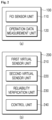
- FIG. 2(b) is a diagram schematically illustrating the internal configuration of the RTO control device according to an embodiment of the present invention.
- the RTO control device 200 of the present invention may include the following configuration.
- the first virtual sensor unit 210 is a training-based virtual sensor for estimating the VOC inflow amount by machine learning by utilizing the RTO operation data.
- the first virtual sensor unit 210 generates a first VOC calculation model using the RTO operation data and FID sensor measurement values acquired from each RTO, and estimates/predicts the VOC inflow amount from operation data of each RTO through the generated first VOC calculation model as an output value of the training-based sensor.
- the first virtual sensor unit 210 may be configured to include the following detailed configuration.
- the first operation data input unit is configured to receive operation data measured in real time from the operation data measurement unit 120 of each of the plurality of RTOns 100_1, 100_2,..., 100_n.
- the VOC inflow amount estimation ML training unit generates the first VOC calculation model, which is a VOC inflow amount estimation model, by performing machine learning in which operation data of each RTO received from the first operation data input unit and the derived factor generated from the operation data are used as an input and the FID sensor measurement value of the FID sensor unit 110 is used as an output.
- FIG. 3 is a diagram illustrating a first VOC calculation model training process according to an embodiment of the present invention.
- a process of training the first VOC calculation model is performed in a way of inputting the input variable composed of RTO operation data and the derived factor generated therefrom to two hidden layers and conducting supervised learning with the FID sensor measurement value VOC1 as a true value.
- the first VOC calculation model is an artificial intelligence neural network model trained by using the VOC inflow measurement values of the FID sensor unit 110 and the RTO operation data corresponding to the VOC inflow measurement values.
- the derived factor may include the chamber temperature change dT acquired from the chamber temperature of the RTO operation data, and the bed upper and lower temperature difference acquired from the bed upper/lower temperatures, as described above.
- Such a first virtual sensor unit 210 estimates/predicts the VOC inflow amount of the corresponding RTO from the RTO operation data acquired from the plurality of RTOns 100_1, 100_2,..., 100_n using the trained first VOC calculation model, and the output value thereof may be referred to as a training-based virtual sensor prediction value VOC2.
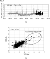
- FIG. 4 is a diagram illustrating an example of a result of applying the trained VOC inflow amount estimation model (first VOC calculation model) according to an embodiment of the present invention.
- the light gray graph is the VOC sensor measurement value over a period of time
- the dark grey graph is the VOC inflow amount predicted value in the supervised learning process using the VOC sensor measurement values and RTO operation data corresponding to the VOC sensor measurement values
- the black graph shows the VOC inflow amount estimated/calculated from actual RTO operation data by using the trained model.
- the VOC sensor which is a physical sensor
- the predicted value (black graph) from the trained model are mutually compared with each other, it is possible to check a time point at which a difference of a predetermined reference value or more occurs, and through this, the VOC sensor measurement error can be minimized by diagnosing/verifying the VOC sensor measurement value at the corresponding time point.
- FIG. 4(b) it is possible to check the calibration time point through the comparison between the actual measured value of the VOC sensor and the VOC inflow predicted value estimated by applying the trained model, and thus the diagnosis/verification of the VOC sensor measurement value can be performed to reduce the measurement error.
- the second virtual sensor unit 220 is a theory-based virtual sensor equipped with a second VOC calculation model for calculating the VOC inflow amount of RTO by using VOC combustion energy. More specifically, it is configured to predict the VOC inflow amount and/or concentration based on the difference between the combustion energy of fuel and the hot air temperature rise energy generated inside the RTO.
- the second virtual sensor unit 220 may be configured to include the following detailed configuration.
- the second operation data input unit is configured to receive RTO operation data measured in real time from the operation data measurement unit 120 of each of the plurality of RTOns 100_1, 100_2,..., 100_n.
- the combustion energy calculation unit calculates combustion energy Q 1 of the fuel LNG by the following.
- Q 1 LNG input ⁇ 43 ,950
- 43,950 refers to the specific heat capacity, which is the heat energy required to raise the temperature of a unit mass of matter by 1 degree.
- the energy generated by combustion per 1Nm 3 of LNG fuel is 43.95 MJ. This was converted into a unit kJ and calculated and a value of 43,950 is used use as the specific heat capacity.
- Each unit is LNG input amount [Nm 3 /hr] and 43,950 [kJ/Nm 3 ], and thus the unit of combustion energy of LNG fuel is [kJ/hr].
- the LNG input amount can be measured by using a conventional LNG inflow amount measuring instrument (sensor).
- the LNG inflow amount measurement sensor may be disposed in a pipe directly connected to the RTO to measure the flow rate of LNG.
- the flow sensor is typically preferably located near the RTO.
- the hot air temperature rise energy before/after combustion calculation unit calculates energy Q2 required for the temperature rise of the air flowing into the RTO by Equation 2 below.
- Q 2 m ⁇ Cp ⁇ T 1 ⁇ T 2
- m means the air flow rate. This is calculated from differential pressure data of the air flow sensor or a pressure sensor at an input end and a pressure sensor at an output end of the blower.
- Cp is computed from 101,325 286.9 ⁇ air temperature + 273.15 .
- pressure density ⁇ gas constant ⁇ temperature
- 101,325 (Pa) is the pressure
- 286.9 (kJ/kg) is the gas constant
- 273.15 is the absolute zero value.
- the above Equation 2 corresponds to the case where the unit of the air flow rate m is [kg/hr].
- the unit of the air flow rate m is [m 3 /hr]
- the above Equation 2 may be further multiplied by an air density value (e.g., 120).
- T1 is the temperature of the bed inlet temperature
- T2 is the temperature after combustion, which is the chamber outlet temperature. Since a structure in which the air introduced into the blower flows into the bed inlet and exits to the chamber outlet in the RTO chamber is adopted, temperature sensors are disposed at respective locations of the bed inlet and chamber outlet to measure the temperatures before/after combustion, respectively. More specifically, when the heat storage material is configured in two stages, the temperature sensor located inside the RTO is usually located before/after passing the first heat storage material, after passing the second heat storage material, in a combustion chamber, etc.
- the combustion chamber temperature, the temperature after combustion, the temperature after passing the second heat storage material, the temperature before combustion that is, the temperature value immediately after passing through all the heat storage materials may be used.
- the VOC inflow amount calculation unit calculates the VOC inflow amount by Equation 3 below by using the combustion energy Q1 calculated by the combustion energy calculation unit and the energy Q2 required for the temperature rise of the air flowing into the RTO calculated in the hot air temperature rise energy before/after combustion calculation unit.
- VOC inflow amount Q 3 VOC heat of combustion
- Q3 Q2 - Q1, which refers to the value acquired by subtracting the combustion energy from hot air temperature rise before/after combustion.
- VOC heat of combustion is different for each VOC material, and can be obtained in a known manner using standard enthalpy of formation.
- the second virtual sensor unit may further include an LEL concentration calculation unit for calculating the LEL concentration (%) of the VOC by Equation 4 below.
- (Q2 - Q1) is the difference between the hot air temperature rise energy before/after combustion Q2 calculated by Equation 2 and the combustion energy Q1 calculated by Equation 1 above, that is, energy generated by the combustion of VOC.
- 1.93 is a value indicating the density of the VOC substance Butene. Since the density of Butene is about 1.93 times that of air, the density of VOC (Butene) is obtained by multiplying the part 101,325 286.9 ⁇ air temperature + 273.15 , which is a part to obtain the density of air, by 1.93.
- LEL 100% is 1.6%.
- LEL 1% means that the ratio of air and Butene is 0.016%, that is, it means that 0.00016 m 3 /hr of Butene is contained when the air flow rate is 100 m 3 /hr.
- the LEL concentration (%) of VOC since it can be calculated through the ratio of the VOC inflow amount and the air flow rate calculated through Equations 1 to 3 above, it can be set to obtain the VOC inflow amount or LEL concentration (%) as an output value of the theory-based virtual sensor, which is the final output value of the second virtual sensor unit 220, if necessary.
- the reliability verification unit 230 has a configuration in which the VOC sensor measurement value is received from each of the plurality of RTOns 100_1, 100_2,..., 100_n, and based on this, the VOC sensor reliability of the RTO or the presence or absence of the VOC sensor (FID sensor unit 110) is verified.
- VOC sensor measurement value satisfies any one of the following two cases, it may be determined that the corresponding VOC sensor reliability is low.
- FIGS. 5 and 6 are diagrams illustrating an example of determining that the VOC sensor reliability is low according to an embodiment of the present invention.
- the VOC sensor measurement value when the VOC sensor measurement value does not change for a predetermined time or more, it may be determined that the reliability of the VOC sensor is low.
- the VOC sensor measurement value exceeds the reference value occurs by a predetermined number of times or more even though there is no change beyond the reference range in the RTO operation data, it may be determined that the reliability of the corresponding VOC sensor is low.
- the change in the chamber temperature value among the RTO operation data is displayed in thick line, and the VOC sensor measurement value is displayed in a thin line.
- the VOC sensor reliability of the corresponding RTO is low, and, for example, a low signal indicating the same may be output.
- both the first and second cases are not applicable, it is determined that the VOC sensor reliability of the corresponding RTO is high, and, for example, a high signal indicating the same may be output.
- the control unit 240 is configured to acquire the calculated value of VOC inflow amount from any one of the first virtual sensor unit 210 and the second virtual sensor unit 220 according to the verification result of the reliability verification unit 230 and the presence or absence of the FID sensor for each of RTOs 100_1, 100_2,..., 100_n, and generate a diagnostic alarm for the VOC sensor measurement value of the corresponding RTO through mutual comparison between the acquired VOC inflow amount from the virtual sensor with the VOC sensor measurement value of the FID sensor unit 110.
- the virtual sensor selection unit may select any one of the first virtual sensor unit 210 and the second virtual sensor unit 220 according to the verification result of the reliability verification unit 230 and the presence or absence of the FID sensor for each of RTOs 100_1, 100_2,..., 100_n, and calculate and acquire the VOC inflow amount therefrom.
- the virtual sensor prediction value of the corresponding RTO may be calculated/acquired from the VOC inflow amount from the first virtual sensor unit 210.
- the virtual sensor prediction value of the corresponding RTO may be calculated/acquired from the VOC inflow amount from the second virtual sensor unit 220.
- the diagnostic alarm generation unit mutually compares the VOC inflow amount from the first virtual sensor unit or the second virtual sensor unit acquired by the virtual sensor selection unit with the VOC inflow measurement value of the FID sensor of the corresponding RTO at the same time point, and generates a diagnostic alarm for the VOC sensor measurement value according to the comparison result.
- a diagnostic alarm may be generated to prompt the user to verify the corresponding VOC sensor measurement value.
- the system for verifying the VOC measurement sensor of the RTO using the virtual sensor is configured to include the plurality of RTOns 100_1, 100_2,..., 100_n and the RTO control device 200 for controlling the RTOns.
- the method for verifying the VOC measurement sensor of such a system may include the following steps
- the data measurement and collection step is a step of collecting operation data and VOC sensor measurement values measured in real time at regular intervals from each of the plurality of RTOns 100_1, 100_2,..., 100_n.
- real-time VOC sensor measurement values and RTO operation data are collected from the FID sensor unit 110 and the operation data measurement unit 120, which is composed of various sensors, provided for each of the RTOs 100_1, 100_2,..., 100_n.
- the VOC sensor verification and virtual sensor selection step is a step of verifying the reliability of the VOC sensor of the corresponding RTO based on the collected VOC sensor measurement values for each of the RTOs 100_1, 100_2,..., 100_n and selecting one of the training-based virtual sensor and the theory-based virtual sensor based on the verification result.
- VOC sensor reliability verification reference has been described in detail with reference to FIGS. 5 and 6 in the system configuration above, a detailed description thereof will be omitted.
- the training-based virtual sensor equipped with the first VOC calculation model trained to estimate the VOC inflow amount using the RTO operation data is selected.
- the theory-based virtual sensor equipped with the second VOC calculation model that calculates the VOC inflow amount using VOC combustion energy is selected.
- the training-based virtual sensor is selected, and when it is determined that the sensor reliability is high, the theory-based virtual sensor is selected.
- the virtual sensor selected in this way can be used to determine whether or not diagnosis of the VOC sensor value of the RTO is necessary by using the predicted value obtained from the corresponding virtual sensor in a step to be described later.
- the virtual sensor prediction value acquisition step is a step of acquiring the predicted value from the selected virtual sensor for each RTO in the VOC verification and virtual sensor selection step.
- the VOC inflow amount estimated using the operation data of the RTO through the first VOC calculation model from training-based virtual sensor can be acquired as a virtual sensor prediction value VOC2.
- the first VOC calculation model is an artificial intelligence neural network model generated by inputting input variables composed of RTO operation data and derived factors generated therefrom into two hidden layers, and conducting supervised learning by using the VOC sensor measurement value VOC1 as a true value.
- the VOC inflow amount calculated from the VOC combustion energy of the RTO through the second VOC calculation model using Equations 1 to 4 above can be acquired as a virtual sensor prediction value VOC3.
- the VOC inflow amount can be acquired from the selected virtual sensor according to the VOC sensor reliability level for each RTO.
- the sensor data comparison step is a step of mutually comparing the VOC inflow amount, which is the virtual sensor prediction value acquired for each RTO through the virtual sensor prediction value acquisition step, with the collected VOC sensor measurement values at the same time point.
- VOC sensor measurement value VOC1_2 and a training-based virtual sensor prediction value VOC2_2 or a theory-based virtual sensor prediction value VOC3_2 at time t of the second RTO 100_2 are mutually compared with each other.
- the diagnostic alarm generation step is a step of generating a diagnostic alarm for the VOC sensor value of the corresponding RTO when there is a difference between the virtual sensor prediction value and the VOC sensor measurement value by a predetermined reference value or more, as a result of the comparison.
- a diagnostic alarm is generated to prompt the user to verify the VOC sensor measurement value.
Landscapes
- Engineering & Computer Science (AREA)
- Chemical & Material Sciences (AREA)
- Health & Medical Sciences (AREA)
- Life Sciences & Earth Sciences (AREA)
- Physics & Mathematics (AREA)
- General Health & Medical Sciences (AREA)
- General Physics & Mathematics (AREA)
- Analytical Chemistry (AREA)
- Biochemistry (AREA)
- Immunology (AREA)
- Pathology (AREA)
- Combustion & Propulsion (AREA)
- General Engineering & Computer Science (AREA)
- Mechanical Engineering (AREA)
- Environmental & Geological Engineering (AREA)
- Food Science & Technology (AREA)
- Medicinal Chemistry (AREA)
- Library & Information Science (AREA)
- Other Investigation Or Analysis Of Materials By Electrical Means (AREA)
- Theoretical Computer Science (AREA)
- Molecular Biology (AREA)
- Incineration Of Waste (AREA)
- Biomedical Technology (AREA)
- Computational Linguistics (AREA)
- Data Mining & Analysis (AREA)
- Evolutionary Computation (AREA)
- Computing Systems (AREA)
- Mathematical Physics (AREA)
- Software Systems (AREA)
- Biophysics (AREA)
- Artificial Intelligence (AREA)
Abstract
Description
- The present invention relates to a virtual sensor system for measuring a VOC inflow amount of an RTO and a method for verifying a VOC measurement sensor using the same, more specifically, to a system and method for capable of verifying the reliability of the VOC measurement sensor using a two methods-based virtual sensor.
- A regenerative thermal oxidizer (hereinafter referred to as 'RTO') refers to a device that incinerates and removes volatile organic compounds (VOC) gas generated in a process. The RTO includes a combustion chamber and a predetermined number of beds made of a heat storage material to increase a heat recovery rate. On the other hand, since the RTO uses the thermal storage material, there is a risk of a safety accident occurring upon a sudden temperature change. In particular, when a high concentration of VOC is introduced, a rapid temperature increase may occur within a few seconds. Continuous monitoring of an amount of VOC flowing into the RTO is necessary. In order to solve this problem, in general, a method of monitoring the VOC inflow amount using a sensor that measures the amount of VOC flowing into the RTO in real time is being used. However, a flame ionization detector (FID) sensor, which is known to be the most reliable among VOC measuring sensors, may also cause a measurement error, which makes it difficult to accurately determine the VOC inflow amount.
- As a related prior art, there is
Korean Patent No. 10-1607878 - The present invention is to solve the problems described above, and to provide a virtual sensor system that can be used in parallel with the VOC measurement sensor to check a calibration time point and a method for diagnosing a VOC measurement sensor using the same.
- In order to solve the problems described above, the present invention provides a virtual sensor system for measuring an VOC inflow amount of an RTO, the virtual sensor system including a plurality of RTOs and an RTO control device for controlling the RTOs, in which the RTO control device comprises a reliability verification unit that verifies the presence or absence or reliability of a FID sensor, a first virtual sensor unit equipped with a first VOC calculation model trained to estimate the VOC inflow amount by using RTO operation data, a second virtual sensor unit equipped with a second VOC calculation model for calculating the VOC inflow amount by using VOC combustion energy, and a control unit that controls operations of the first virtual sensor unit and the second virtual sensor unit according to the verification result of the reliability verification unit and the presence or absence of the FID sensor.
- In this case, each RTO is configured to include a flame ionization detector(FID) sensor unit that measures the VOC inflow amount at regular intervals, and an operation data measurement unit that measures the RTO operation data at regular intervals. The reliability verification unit determines that the FID sensor reliability is low if any one of a case in which a VOC inflow measurement value input from the FID sensor unit of each RTO does not change for a predetermined time or more and a case in which the VOC inflow measurement value exceeds a reference value even though there is no change beyond a reference range in the RTO operation data is satisfied.
- The control unit may be configured to include a virtual sensor selection unit that calculates the VOC inflow amount from the first virtual sensor unit when it is determined that the FID sensor exists and the FID sensor reliability is high, and calculates the VOC inflow amount from the second virtual sensor unit when it is determined that the FID sensor does not exist or the FID sensor reliability is low, as a result of the verification of the reliability verification unit. The control unit may further include a diagnostic alarm generation unit that mutually compares the VOC inflow amount from the first virtual sensor unit or the second virtual sensor unit acquired by the virtual sensor selection unit with the VOC inflow measurement value of the FID sensor at the same time point, and generates a diagnostic alarm for the VOC inflow measurement value according to the comparison result.
- The first VOC calculation model of the first virtual sensor unit may be an artificial intelligence neural network model trained by using the VOC inflow measurement values measured by the FID sensor unit and the RTO operation data corresponding to the VOC inflow measurement values. The second VOC calculation model of the second virtual sensor unit may calculate from combustion energy of the RTO, hot air temperature rise energy before/after combustion, and combustion energy of the VOC.
- In addition, the present invention provides a method for verifying a VOC measurement sensor of an RTO using a virtual sensor, the method including a data measurement and collection step of collecting operation data and a VOC sensor measurement value measured at regular intervals from each of a plurality of RTOs, a VOC sensor verification and virtual sensor selection step of verifying VOC sensor reliability of the RTO based on the collected VOC sensor measurement values for each RTO and selecting one of a training based virtual sensor and a theory-based virtual sensor based on the verification result, a virtual sensor prediction value acquisition step of acquiring a calculated value of VOC inflow amount from the virtual sensor selected for each RTO in the VOC sensor verification and virtual sensor selection step, a sensor data comparison step of mutually comparing the calculated value of VOC inflow amount acquired for each RTO through the virtual sensor prediction value acquisition step with the collected VOC sensor measurement value at the same time point, and a diagnostic alarm generation step of generating a diagnostic alarm for the VOC sensor measurement value when there is a difference between the calculated value of VOC inflow amount and the VOC sensor measurement value by a predetermined reference value or more as a result of the comparison.
- In the VOC sensor verification and virtual sensor selection step, a training-based virtual sensor is selected if the VOC sensor exists and the VOC sensor reliability is greater than or equal to a predetermined reference and a theory-based virtual sensor is selected if the VOC sensor does not exist or the VOC sensor reliability is less than the predetermined reference. The training-based virtual sensor may calculate the VOC inflow amount using RTO operation data through an artificial intelligence neural network model trained by using the VOC sensor measurement values and the RTO operation data corresponding to the VOC sensor measurement values.
- According to an embodiment of the present invention, a virtual sensor that can be used in parallel with the VOC measurement sensor to check the calibration time point and ultimately can replace the VOC measurement sensor is provided. Therefore, it is possible to reduce the risk of safety accidents by minimizing the measurement error of the existing VOC measurement sensor to accurately grasp the VOC inflow amount of the RTO.
-
-
FIG. 1 is a diagram schematically illustrating the overall configuration of a virtual sensor system for measuring a VOC inflow amount of an RTO according to an embodiment of the present invention. -
FIG. 2 is a diagram schematically illustrating an internal configuration of the RTO and an RTO control device according to an embodiment of the present invention. -
FIG. 3 is a diagram illustrating a first VOC calculation model training process according to an embodiment of the present invention. -
FIG. 4 is a diagram illustrating an example of a result of applying the first VOC calculation model according to an embodiment of the present invention. -
FIGS. 5 and 6 are diagrams illustrating examples of VOC sensor reliability verification criteria according to an embodiment of the present invention. - Hereinafter, embodiments of the present invention will be described in detail with reference to the accompanying drawings so that those of ordinary skill in the art can easily embody the present invention. However, the present invention may be implemented in various different forms and is not limited to the embodiments described herein. In order to clearly describe the present invention in the drawings, parts irrelevant to the description are omitted, and similar reference numerals are attached to similar parts throughout the specification.
- Hereinafter, the present invention will be described in detail with reference to the drawings.
- The RTO operation data refers to measurement values of various sensors disposed inside the RTO during RTO operation.
- Specifically, the RTO operation data may include an RTO blower driving power amount, an LNG fuel input amount, a bed inlet temperature/pressure, a chamber temperature, a chamber outlet temperature, bed upper/lower temperature, etc. Accordingly, various sensors may be composed of sensors necessary for measuring operation data, such as a blower power amount sensor, a LNG fuel amount sensor, a bed inlet temperature/pressure sensor, a chamber temperature sensor, a chamber outlet temperature sensor, and a bed upper/lower temperature sensor.
- Meanwhile, the derived factors are values acquired from the RTO operation data, and may include a chamber temperature change (dT), a bed upper/lower temperature difference (Tbed_diff), etc.
- The VOC sensor refers to a physical sensor that is disposed in each of a plurality of RTOs and measures the amount of VOC flowing into the corresponding RTO in real time. In the present invention, the VOC sensor may be implemented as a commonly known flame ionization detector (FID).
- In the present invention, the 'VOC sensor' may be used interchangeably with a 'FID sensor unit'.
- The virtual sensor is used in parallel with the VOC sensor to check a calibration time point, and is a sensor developed to ultimately replace the physical sensor. The virtual sensor is implemented based on the concept of inversely calculating a VOC inflow amount using the RTO operation data.
- This virtual sensor is composed of a training-based virtual sensor that estimates the VOC inflow amount using machine learning techniques using the RTO operation data and derived factors obtained therefrom and a theory-based virtual sensor that is based on the First Principle and predicts VOC inflow amount/concentration based on a difference between fuel combustion energy and hot air temperature rise energy generated inside the RTO.
- The virtual sensor system for measuring the VOC inflow amount of the RTO according to the present invention is a system for monitoring the VOC inflow amount of a each regenerative thermal oxidizer (RTO) of a plurality of regenerative thermal oxidizers RTO1, RT02,..., RTOn.
-
FIG. 1 is a diagram schematically illustrating the overall configuration of the virtual sensor system for measuring the VOC inflow amount of the RTO according to an embodiment of the present invention. - Referring to
FIG. 1 , the system of the present invention is largely configured with a plurality of RTOn 100_1, 100_2,..., 100_n and aRTO control device 200 for controlling the RTOns. -
FIG. 2(a) is a diagram schematically illustrating the internal configuration of the RTO according to an embodiment of the present invention. - Referring to
FIG. 2(a) , respective RTOn 100_1, 100_2,.., 100_n included in the system of the present invention may include the following configuration. - The
FID sensor unit 110 is composed of the flame ionization detector (FID) and is a VOC sensor that periodically measures the VOC inflow amount in real time. For example, as illustrated inFIG. 3 , it may be disposed near a blower to detect/measure the amount of VOC introduced. A value measured by theFID sensor unit 110 may be referred to as an FID sensor measurement value, a VOC sensor measurement value, or VOC1 hereinafter. - The operation
data measurement unit 120 is configured with various sensors necessary for measuring RTO operation data including the RTO blower driving power amount, the LNG fuel input amount, the bed inlet temperature/pressure, the chamber temperature, the chamber outlet temperature, the bed upper/lower temperature, etc., and is configured to measure the operation data in real time at regular intervals. -
FIG. 2(b) is a diagram schematically illustrating the internal configuration of the RTO control device according to an embodiment of the present invention. - Referring to
FIG. 2(b) , theRTO control device 200 of the present invention may include the following configuration. - The first
virtual sensor unit 210 is a training-based virtual sensor for estimating the VOC inflow amount by machine learning by utilizing the RTO operation data. - More specifically, the first
virtual sensor unit 210 generates a first VOC calculation model using the RTO operation data and FID sensor measurement values acquired from each RTO, and estimates/predicts the VOC inflow amount from operation data of each RTO through the generated first VOC calculation model as an output value of the training-based sensor. - The first
virtual sensor unit 210 may be configured to include the following detailed configuration. - The first operation data input unit is configured to receive operation data measured in real time from the operation
data measurement unit 120 of each of the plurality of RTOns 100_1, 100_2,..., 100_n. - The VOC inflow amount estimation ML training unit generates the first VOC calculation model, which is a VOC inflow amount estimation model, by performing machine learning in which operation data of each RTO received from the first operation data input unit and the derived factor generated from the operation data are used as an input and the FID sensor measurement value of the
FID sensor unit 110 is used as an output. -
FIG. 3 is a diagram illustrating a first VOC calculation model training process according to an embodiment of the present invention. - Referring to
FIG. 3 , a process of training the first VOC calculation model is performed in a way of inputting the input variable composed of RTO operation data and the derived factor generated therefrom to two hidden layers and conducting supervised learning with the FID sensor measurement value VOC1 as a true value. - That is, the first VOC calculation model is an artificial intelligence neural network model trained by using the VOC inflow measurement values of the
FID sensor unit 110 and the RTO operation data corresponding to the VOC inflow measurement values. - Here, the derived factor may include the chamber temperature change dT acquired from the chamber temperature of the RTO operation data, and the bed upper and lower temperature difference acquired from the bed upper/lower temperatures, as described above.
- Such a first
virtual sensor unit 210 estimates/predicts the VOC inflow amount of the corresponding RTO from the RTO operation data acquired from the plurality of RTOns 100_1, 100_2,..., 100_n using the trained first VOC calculation model, and the output value thereof may be referred to as a training-based virtual sensor prediction value VOC2. -
FIG. 4 is a diagram illustrating an example of a result of applying the trained VOC inflow amount estimation model (first VOC calculation model) according to an embodiment of the present invention. - When looking at the graph shown in
FIG. 4 (a) , the light gray graph is the VOC sensor measurement value over a period of time, the dark grey graph is the VOC inflow amount predicted value in the supervised learning process using the VOC sensor measurement values and RTO operation data corresponding to the VOC sensor measurement values, and the black graph shows the VOC inflow amount estimated/calculated from actual RTO operation data by using the trained model. When the actual measured value (light gray graph) of the VOC sensor, which is a physical sensor, and the predicted value (black graph) from the trained model are mutually compared with each other, it is possible to check a time point at which a difference of a predetermined reference value or more occurs, and through this, the VOC sensor measurement error can be minimized by diagnosing/verifying the VOC sensor measurement value at the corresponding time point. In addition, as illustrated inFIG. 4(b) , it is possible to check the calibration time point through the comparison between the actual measured value of the VOC sensor and the VOC inflow predicted value estimated by applying the trained model, and thus the diagnosis/verification of the VOC sensor measurement value can be performed to reduce the measurement error. - The second
virtual sensor unit 220 is a theory-based virtual sensor equipped with a second VOC calculation model for calculating the VOC inflow amount of RTO by using VOC combustion energy. More specifically, it is configured to predict the VOC inflow amount and/or concentration based on the difference between the combustion energy of fuel and the hot air temperature rise energy generated inside the RTO. - The second
virtual sensor unit 220 may be configured to include the following detailed configuration. - The second operation data input unit is configured to receive RTO operation data measured in real time from the operation
data measurement unit 120 of each of the plurality of RTOns 100_1, 100_2,..., 100_n. - The combustion energy calculation unit calculates combustion energy Q1 of the fuel LNG by the following.

- Here, 43,950 refers to the specific heat capacity, which is the heat energy required to raise the temperature of a unit mass of matter by 1 degree. The energy generated by combustion per 1Nm3 of LNG fuel is 43.95 MJ. This was converted into a unit kJ and calculated and a value of 43,950 is used use as the specific heat capacity. Each unit is LNG input amount [Nm3/hr] and 43,950 [kJ/Nm3], and thus the unit of combustion energy of LNG fuel is [kJ/hr].
- On the other hand, the LNG input amount (flow rate) can be measured by using a conventional LNG inflow amount measuring instrument (sensor). Although not illustrated in the drawings, the LNG inflow amount measurement sensor may be disposed in a pipe directly connected to the RTO to measure the flow rate of LNG. For complete combustion, since it is necessary to adjust the amount of air input along with the amount of LNG input, the flow sensor is typically preferably located near the RTO.
- The hot air temperature rise energy before/after combustion calculation unit calculates energy Q2 required for the temperature rise of the air flowing into the RTO by
Equation 2 below.
- Here, m means the air flow rate. This is calculated from differential pressure data of the air flow sensor or a pressure sensor at an input end and a pressure sensor at an output end of the blower.
- Further, Cp is computed from

above Equation 2 corresponds to the case where the unit of the air flow rate m is [kg/hr]. When the unit of the air flow rate m is [m3/hr], theabove Equation 2 may be further multiplied by an air density value (e.g., 120). - Further, T1 is the temperature of the bed inlet temperature, and T2 is the the temperature after combustion, which is the chamber outlet temperature. Since a structure in which the air introduced into the blower flows into the bed inlet and exits to the chamber outlet in the RTO chamber is adopted, temperature sensors are disposed at respective locations of the bed inlet and chamber outlet to measure the temperatures before/after combustion, respectively. More specifically, when the heat storage material is configured in two stages, the temperature sensor located inside the RTO is usually located before/after passing the first heat storage material, after passing the second heat storage material, in a combustion chamber, etc. Thus, according to an embodiment of the present invention, the combustion chamber temperature, the temperature after combustion, the temperature after passing the second heat storage material, the temperature before combustion, that is, the temperature value immediately after passing through all the heat storage materials may be used.
- The VOC inflow amount calculation unit calculates the VOC inflow amount by
Equation 3 below by using the combustion energy Q1 calculated by the combustion energy calculation unit and the energy Q2 required for the temperature rise of the air flowing into the RTO calculated in the hot air temperature rise energy before/after combustion calculation unit.
- Here, Q3 = Q2 - Q1, which refers to the value acquired by subtracting the combustion energy from hot air temperature rise before/after combustion.
- On the other hand, the VOC heat of combustion is different for each VOC material, and can be obtained in a known manner using standard enthalpy of formation.
- The second virtual sensor unit may further include an LEL concentration calculation unit for calculating the LEL concentration (%) of the VOC by
Equation 4 below.
- Here, (Q2 - Q1) is the difference between the hot air temperature rise energy before/after combustion Q2 calculated by
Equation 2 and the combustion energy Q1 calculated byEquation 1 above, that is, energy generated by the combustion of VOC. - Further, 1.93 is a value indicating the density of the VOC substance Butene. Since the density of Butene is about 1.93 times that of air, the density of VOC (Butene) is obtained by multiplying the part

- Further, in the case of Butene,
LEL 100% is 1.6%.LEL 1% means that the ratio of air and Butene is 0.016%, that is, it means that 0.00016 m3/hr of Butene is contained when the air flow rate is 100 m3/hr. - Here, 1.93 and 0.016 correspond to the case where the VOC material is Butene, and they vary depending on the VOC material.
- In the case of the LEL concentration (%) of VOC, since it can be calculated through the ratio of the VOC inflow amount and the air flow rate calculated through
Equations 1 to 3 above, it can be set to obtain the VOC inflow amount or LEL concentration (%) as an output value of the theory-based virtual sensor, which is the final output value of the secondvirtual sensor unit 220, if necessary. - The
reliability verification unit 230 has a configuration in which the VOC sensor measurement value is received from each of the plurality of RTOns 100_1, 100_2,..., 100_n, and based on this, the VOC sensor reliability of the RTO or the presence or absence of the VOC sensor (FID sensor unit 110) is verified. - As a reference for verifying the VOC sensor reliability, if the VOC sensor measurement value satisfies any one of the following two cases, it may be determined that the corresponding VOC sensor reliability is low.
-
FIGS. 5 and 6 are diagrams illustrating an example of determining that the VOC sensor reliability is low according to an embodiment of the present invention. - As a first case, as illustrated in
FIG. 5 , when the VOC sensor measurement value does not change for a predetermined time or more, it may be determined that the reliability of the VOC sensor is low. - As a second case, as illustrated in
FIG. 6 , if a case where the VOC sensor measurement value exceeds the reference value occurs by a predetermined number of times or more even though there is no change beyond the reference range in the RTO operation data, it may be determined that the reliability of the corresponding VOC sensor is low. Here, in the case ofFIG. 6 , the change in the chamber temperature value among the RTO operation data is displayed in thick line, and the VOC sensor measurement value is displayed in a thin line. - When any one of the first and second cases is satisfied, it is determined that the VOC sensor reliability of the corresponding RTO is low, and, for example, a low signal indicating the same may be output. On the other hand, when both the first and second cases are not applicable, it is determined that the VOC sensor reliability of the corresponding RTO is high, and, for example, a high signal indicating the same may be output.
- The
control unit 240 is configured to acquire the calculated value of VOC inflow amount from any one of the firstvirtual sensor unit 210 and the secondvirtual sensor unit 220 according to the verification result of thereliability verification unit 230 and the presence or absence of the FID sensor for each of RTOs 100_1, 100_2,..., 100_n, and generate a diagnostic alarm for the VOC sensor measurement value of the corresponding RTO through mutual comparison between the acquired VOC inflow amount from the virtual sensor with the VOC sensor measurement value of theFID sensor unit 110. - The virtual sensor selection unit may select any one of the first
virtual sensor unit 210 and the secondvirtual sensor unit 220 according to the verification result of thereliability verification unit 230 and the presence or absence of the FID sensor for each of RTOs 100_1, 100_2,..., 100_n, and calculate and acquire the VOC inflow amount therefrom. - Specifically, when an FID sensor exists and it is determined that the reliability of the VOC sensor is high (when a high signal is output) as a result of the verification of the
reliability verification unit 230, the virtual sensor prediction value of the corresponding RTO may be calculated/acquired from the VOC inflow amount from the firstvirtual sensor unit 210. - On the other hand, when the FID sensor does not exist or it is determined that the reliability of the VOC sensor is low (when a low signal is output) as a result of the verification of the
reliability verification unit 230, the virtual sensor prediction value of the corresponding RTO may be calculated/acquired from the VOC inflow amount from the secondvirtual sensor unit 220. - The diagnostic alarm generation unit mutually compares the VOC inflow amount from the first virtual sensor unit or the second virtual sensor unit acquired by the virtual sensor selection unit with the VOC inflow measurement value of the FID sensor of the corresponding RTO at the same time point, and generates a diagnostic alarm for the VOC sensor measurement value according to the comparison result.
- As a result of the comparison, when there is a difference between the VOC inflow amount from the first
virtual sensor unit 210 or the secondvirtual sensor unit 220 and the VOC sensor measurement value by a predetermined reference value or more, a diagnostic alarm may be generated to prompt the user to verify the corresponding VOC sensor measurement value. - The system for verifying the VOC measurement sensor of the RTO using the virtual sensor according to an embodiment of the present invention, as described above, is configured to include the plurality of RTOns 100_1, 100_2,..., 100_n and the
RTO control device 200 for controlling the RTOns. The method for verifying the VOC measurement sensor of such a system may include the following steps - The data measurement and collection step is a step of collecting operation data and VOC sensor measurement values measured in real time at regular intervals from each of the plurality of RTOns 100_1, 100_2,..., 100_n.
- More specifically, real-time VOC sensor measurement values and RTO operation data are collected from the
FID sensor unit 110 and the operationdata measurement unit 120, which is composed of various sensors, provided for each of the RTOs 100_1, 100_2,..., 100_n. - The VOC sensor verification and virtual sensor selection step is a step of verifying the reliability of the VOC sensor of the corresponding RTO based on the collected VOC sensor measurement values for each of the RTOs 100_1, 100_2,..., 100_n and selecting one of the training-based virtual sensor and the theory-based virtual sensor based on the verification result.
- Specifically, when any one of a case where the VOC sensor measurement value does not change for a predetermined time or more and a case where the VOC sensor measurement value exceeds the reference value occurs by a predetermined number of times or more even though there is no change beyond the reference range in the RTO operation data is satisfied, it may be determined that the reliability of the VOC sensor of the corresponding RTO is low. Since such a VOC sensor reliability verification reference has been described in detail with reference to
FIGS. 5 and 6 in the system configuration above, a detailed description thereof will be omitted. - Meanwhile, when it is determined that the reliability of the VOC sensor measurement value is high as a result of the verification, the training-based virtual sensor equipped with the first VOC calculation model trained to estimate the VOC inflow amount using the RTO operation data is selected. On the other hand, when it is determined that the reliability of the VOC sensor measurement value is low, the theory-based virtual sensor equipped with the second VOC calculation model that calculates the VOC inflow amount using VOC combustion energy is selected. Here, it is set to select the theory-based virtual sensor even when the VOC sensor does not exist.
- For example, when it is determined that the sensor reliability of the second RTO 100_2 is high, the training-based virtual sensor is selected, and when it is determined that the sensor reliability is low, the theory-based virtual sensor is selected.
- The virtual sensor selected in this way can be used to determine whether or not diagnosis of the VOC sensor value of the RTO is necessary by using the predicted value obtained from the corresponding virtual sensor in a step to be described later.
- The virtual sensor prediction value acquisition step is a step of acquiring the predicted value from the selected virtual sensor for each RTO in the VOC verification and virtual sensor selection step.
- When the selected virtual sensor is the training-based virtual sensor, the VOC inflow amount estimated using the operation data of the RTO through the first VOC calculation model from training-based virtual sensor can be acquired as a virtual sensor prediction value VOC2.
- Here, the first VOC calculation model is an artificial intelligence neural network model generated by inputting input variables composed of RTO operation data and derived factors generated therefrom into two hidden layers, and conducting supervised learning by using the VOC sensor measurement value VOC1 as a true value.
- On the other hand, when the selected virtual sensor is the theory-based virtual sensor, the VOC inflow amount calculated from the VOC combustion energy of the RTO through the second VOC calculation
model using Equations 1 to 4 above can be acquired as a virtual sensor prediction value VOC3. - Through these steps, the VOC inflow amount can be acquired from the selected virtual sensor according to the VOC sensor reliability level for each RTO.
- The sensor data comparison step is a step of mutually comparing the VOC inflow amount, which is the virtual sensor prediction value acquired for each RTO through the virtual sensor prediction value acquisition step, with the collected VOC sensor measurement values at the same time point.
- For example, a VOC sensor measurement value VOC1_2 and a training-based virtual sensor prediction value VOC2_2 or a theory-based virtual sensor prediction value VOC3_2 at time t of the second RTO 100_2 are mutually compared with each other.
- The diagnostic alarm generation step is a step of generating a diagnostic alarm for the VOC sensor value of the corresponding RTO when there is a difference between the virtual sensor prediction value and the VOC sensor measurement value by a predetermined reference value or more, as a result of the comparison.
- When there is a difference between the VOC sensor measurement value and virtual sensor prediction value of the RTO by a predetermined reference value or more, a diagnostic alarm is generated to prompt the user to verify the VOC sensor measurement value.
- Meanwhile, although the technical idea of the present invention has been described in detail according to the above embodiment, it should be noted that the above embodiment is for the purpose of description and not for limitation. Further, those skilled in the art will understand that various embodiments are possible within the scope of the technical idea of the present invention.
Claims (12)
- A virtual sensor system for measuring an VOC inflow amount of an RTO, comprising:a plurality of RTOs; andan RTO control device for controlling the RTOs, whereinthe RTO control device comprisesa reliability verification unit that verifies the presence or absence or reliability of a FID sensor,a first virtual sensor unit equipped with a first VOC calculation model trained to estimate the VOC inflow amount by using RTO operation data,a second virtual sensor unit equipped with a second VOC calculation model for calculating the VOC inflow amount by using VOC combustion energy, anda control unit that controls operations of the first virtual sensor unit and the second virtual sensor unit according to the verification result of the reliability verification unit and the presence or absence of the FID sensor.
- The virtual sensor system of claim 1, wherein
each RTO is configured to comprisea flame ionization detector(FID) sensor unit that measures the VOC inflow amount at regular intervals, andan operation data measurement unit that measures the RTO operation data at regular intervals. - The virtual sensor system of claim 2, wherein
the reliability verification unit determines that
the FID sensor reliability is low if any one of a case in which a VOC inflow measurement value input from the FID sensor unit of each RTO does not change for a predetermined time or more or a case in which the VOC inflow measurement value exceeds a reference value even though there is no change beyond the reference range in the RTO operation data. - The virtual sensor system of claim 3, wherein
the control unit is configured to comprise
a virtual sensor selection unit that calculates the VOC inflow amount from the first virtual sensor unit when it is determined that the FID sensor exists and the FID sensor reliability is high, and calculates the VOC inflow amount from the second virtual sensor unit when it is determined that the FID sensor does not exist or the FID sensor reliability is low, as a result of the verification of the reliability verification unit. - The virtual sensor system of claim 4, wherein
the control unit is configured to further comprise
a diagnostic alarm generation unit that mutually compares the VOC inflow amount from the first virtual sensor unit or the second virtual sensor unit acquired by the virtual sensor selection unit with the VOC inflow measurement value of the FID sensor at the same time point, and generates a diagnostic alarm for the VOC inflow measurement value according to the comparison result. - The virtual sensor system of claim 4, wherein
the first VOC calculation model of the first virtual sensor unit is
an artificial intelligence neural network model trained by using the VOC inflow measurement values measured by the FID sensor unit and the RTO operation data corresponding to the VOC inflow measurement values. - The virtual sensor system of claim 4, wherein
the second VOC calculation model of the second virtual sensor unit calculates from combustion energy of the RTO, hot air temperature rise energy before/after combustion, and combustion energy of the VOC. - The virtual sensor system of claim 7, wherein
a VOC inflow amount VOCf from the second virtual sensor unit is calculated by Equation 1 below,
- A method for verifying a VOC measurement sensor of an RTO using a virtual sensor, the method comprising:a data measurement and collection step of collecting operation data and a VOC sensor measurement value measured at regular intervals from each of a plurality of RTOs;a VOC sensor verification and virtual sensor selection step of verifying VOC sensor reliability of the RTO based on the collected VOC sensor measurement values for each RTO, and selecting one of a training-based virtual sensor and a theory-based virtual sensor based on the verification result;a virtual sensor prediction value acquisition step of acquiring a calculated value of VOC inflow amount from the virtual sensor selected for each RTO in the VOC verification and virtual sensor selection step;a sensor data comparison step of mutually comparing the calculated value of VOC inflow amount acquired for each RTO through the virtual sensor prediction value acquisition step and the collected VOC sensor measurement value at the same time point; anda diagnostic alarm generation step of generating a diagnostic alarm for the VOC sensor measurement value when there is a difference between the calculated value of VOC inflow amount and the VOC sensor measurement value by a predetermined reference value or more as a result of the comparison.
- The method of claim 9, wherein
in the VOC sensor verification and virtual sensor selection step,
a training-based virtual sensor is selected if the VOC sensor exists and the VOC sensor reliability is greater than or equal to a predetermined reference and a theory-based virtual sensor is selected if the VOC sensor does not exist or the VOC sensor reliability is less than the predetermined reference. - The method of claim 10, whereinthe training-based virtual sensor calculatesthe VOC inflow amount using RTO operation data through an artificial intelligence neural network model trained by using the VOC sensor measurement values and the RTO operation data corresponding to the VOC sensor measurement values.
- The method of claim 10, wherein
the theory-based virtual sensor, by using the combustion energy of RTO, hot air temperature rise energy before/after combustion, and combustion energy of VOC, calculates a VOC inflow amount VOCf by Equation 1 below,
Applications Claiming Priority (2)
| Application Number | Priority Date | Filing Date | Title |
|---|---|---|---|
| KR1020220018487A KR102913081B1 (en) | 2022-02-11 | 2022-02-11 | VOC inflow measurement virtual sensor system of RTO and VOC measurement sensor verification method using the same |
| PCT/KR2022/012790 WO2023153571A1 (en) | 2022-02-11 | 2022-08-26 | Virtual sensor system for measuring voc inflow amount of rto and method for verifying voc measurement sensor by using same |
Publications (2)
| Publication Number | Publication Date |
|---|---|
| EP4283293A1 true EP4283293A1 (en) | 2023-11-29 |
| EP4283293A4 EP4283293A4 (en) | 2024-08-21 |
Family
ID=87564617
Family Applications (1)
| Application Number | Title | Priority Date | Filing Date |
|---|---|---|---|
| EP22926169.8A Pending EP4283293A4 (en) | 2022-02-11 | 2022-08-26 | VIRTUAL SENSOR SYSTEM FOR MEASURING VOC INFLUENCE FROM RTO AND METHOD FOR VERIFYING A VOC MEASURING SENSOR USING SAME |
Country Status (6)
| Country | Link |
|---|---|
| US (1) | US20240272129A1 (en) |
| EP (1) | EP4283293A4 (en) |
| JP (1) | JP7592887B2 (en) |
| KR (1) | KR102913081B1 (en) |
| CN (1) | CN117015709A (en) |
| WO (1) | WO2023153571A1 (en) |
Families Citing this family (1)
| Publication number | Priority date | Publication date | Assignee | Title |
|---|---|---|---|---|
| KR102940296B1 (en) | 2023-08-31 | 2026-03-17 | 주식회사 그린시티솔루션 | Method and apparatus for measuring concentration of carbon dioxide and volatile organic compounds |
Family Cites Families (22)
| Publication number | Priority date | Publication date | Assignee | Title |
|---|---|---|---|---|
| US5466418A (en) * | 1993-07-13 | 1995-11-14 | Astec Industries, Inc. | System for the remediation of highly contaminated soils |
| JP2847468B2 (en) * | 1994-04-29 | 1999-01-20 | 川崎重工業株式会社 | Waste Property Estimation Method and Estimation Device for Waste Incinerator |
| CA2235176C (en) * | 1998-04-17 | 2005-08-16 | Newnes Machine Ltd. | Method and apparatus for improved inspection and classification of attributes of a workpiece |
| US6165251A (en) * | 1998-05-05 | 2000-12-26 | The United States Of America As Represented By The Administrator Of The U.S. Environmental Protection Agency | On-line gas chromatograph with sample preparation, concentration, and calibration apparatus for measuring trace organic species from combustor flue gas |
| KR100340967B1 (en) * | 1999-10-08 | 2002-06-20 | 손재익 | Method and apparatus for detecting fault using General Regression Neural Network |
| JP2003057221A (en) * | 2001-08-13 | 2003-02-26 | Showa Kankyo Engineering Kk | Method and instrument of continuously analyzing exhaust gas from incinerator for hazardous air pollutant |
| CN101387127B (en) * | 2004-12-14 | 2011-03-09 | 株式会社东芝 | Rainwater drain control system and method |
| US7505844B2 (en) | 2005-11-18 | 2009-03-17 | General Electric Company | Model-based iterative estimation of gas turbine engine component qualities |
| JP2008275383A (en) * | 2007-04-26 | 2008-11-13 | Hitachi Engineering & Services Co Ltd | Concentration measurement method and apparatus for mixed component system, and energy saving or exhaust purification equipment operation control system using the apparatus. |
| US7787969B2 (en) * | 2007-06-15 | 2010-08-31 | Caterpillar Inc | Virtual sensor system and method |
| JP2010537192A (en) * | 2007-08-17 | 2010-12-02 | インスティトゥット・フォア・エネルギテクニック | System and method for virtual sensing based on empirical ensemble of gas emissions |
| JP5339935B2 (en) * | 2009-01-23 | 2013-11-13 | パナソニック株式会社 | Deodorizing device and safe driving method thereof |
| KR101372489B1 (en) * | 2012-10-09 | 2014-03-10 | 주식회사 엠앤디 | System for monitoring low pressure turbine using smart sensor |
| JP6170799B2 (en) * | 2013-10-02 | 2017-07-26 | メタウォーター株式会社 | Organic waste energy estimation method and apparatus |
| CN103677838A (en) * | 2013-12-17 | 2014-03-26 | 北京奥特美克科技股份有限公司 | RTU sensor adaptation layer based on virtual sensors and design method of RTU sensor adaptation layer |
| KR101607878B1 (en) | 2014-06-16 | 2016-04-01 | 건국대학교 산학협력단 | System and method for providing air quality information by integrating virtual sensor and monitoring sensor |
| WO2017164854A1 (en) * | 2016-03-22 | 2017-09-28 | Halliburton Energy Services, Inc. | Calibration module for pooled optical sensors in downhole fluid analysis |
| EP3435184B1 (en) * | 2017-07-28 | 2024-04-17 | Siemens Aktiengesellschaft | System, method and control unit for controlling a technical system |
| KR101894541B1 (en) * | 2017-11-21 | 2018-10-04 | 주식회사 나라컨트롤 | Prediction method for characteristic factor based on artificial intelligence and Prediction method for energy consumption of building using the same |
| EP3525055A1 (en) * | 2018-02-12 | 2019-08-14 | Siemens Aktiengesellschaft | Diagnostic system with a virtual sensor |
| KR102756234B1 (en) * | 2019-08-13 | 2025-01-15 | 한화오션 주식회사 | VOCs REDUCTION SYSTEM AND METHOD |
| KR102298489B1 (en) * | 2020-01-30 | 2021-09-03 | 전남대학교산학협력단 | Building Energy Failure Diagnosis and Analysis System with integrated Virtual sensor and Deep learning, and Building Energy Failure Diagnosis and Analysis Method |
-
2022
- 2022-02-11 KR KR1020220018487A patent/KR102913081B1/en active Active
- 2022-08-26 EP EP22926169.8A patent/EP4283293A4/en active Pending
- 2022-08-26 WO PCT/KR2022/012790 patent/WO2023153571A1/en not_active Ceased
- 2022-08-26 JP JP2023553379A patent/JP7592887B2/en active Active
- 2022-08-26 CN CN202280018170.5A patent/CN117015709A/en active Pending
- 2022-08-26 US US18/279,383 patent/US20240272129A1/en active Pending
Also Published As
| Publication number | Publication date |
|---|---|
| US20240272129A1 (en) | 2024-08-15 |
| WO2023153571A1 (en) | 2023-08-17 |
| EP4283293A4 (en) | 2024-08-21 |
| KR102913081B1 (en) | 2026-01-19 |
| JP2024515930A (en) | 2024-04-11 |
| JP7592887B2 (en) | 2024-12-02 |
| CN117015709A (en) | 2023-11-07 |
| KR20230121504A (en) | 2023-08-18 |
Similar Documents
| Publication | Publication Date | Title |
|---|---|---|
| US6898554B2 (en) | Fault detection in a physical system | |
| US5625750A (en) | Catalyst monitor with direct prediction of hydrocarbon conversion efficiency by dynamic neural networks | |
| US6353815B1 (en) | Statistically qualified neuro-analytic failure detection method and system | |
| EP0712509B1 (en) | Virtual continuous emission monitoring system with sensor validation | |
| JPH11510898A (en) | Method and apparatus for detecting and identifying defect sensors in a process | |
| US5970426A (en) | Emission monitoring system | |
| EP3229093B1 (en) | Abnormality diagnosing method and abnormality diagnosing system | |
| US8417432B2 (en) | Method for calculating confidence on prediction in fault diagnosis systems | |
| US20080082470A1 (en) | Infrastructure health monitoring and analysis | |
| Wang et al. | Law-based sensor fault diagnosis and validation for building air-conditioning systems | |
| JP2004529433A (en) | Flow diagnostic system | |
| CA2885163C (en) | Flame instability monitoring with draft pressure and process variable | |
| US7231811B2 (en) | Adaptive leak testing method | |
| EP0545450B1 (en) | Statistically detecting leakage of fluid from a conduit | |
| CN101681155A (en) | Virtual sensor system and method | |
| Ballé | Fuzzy-model-based parity equations for fault isolation | |
| US20240272129A1 (en) | Virtual sensor system for measuring voc inflow amount of rto and method for verifying voc measurement sensor by using same | |
| Tamssaouet et al. | Contribution to Online System-level Prognostics based on Adaptive Degradation Models | |
| Iannetti et al. | Development of model-based fault diagnosis algorithms for MASCOTTE cryogenic test bench | |
| US10921197B2 (en) | Visualization and manipulation of micro-scale calorimeter chamber data matrices | |
| AU757834B2 (en) | Fluid flow measurement | |
| JP2004156258A (en) | Tunnel ventilation control method and device | |
| JPH09190219A (en) | Plant abnormality diagnosis device | |
| JPH08240453A (en) | Gas leak detector | |
| Goto et al. | Intelligent alarm method by fuzzy measure and its application to plant abnormality prediction |
Legal Events
| Date | Code | Title | Description |
|---|---|---|---|
| STAA | Information on the status of an ep patent application or granted ep patent |
Free format text: STATUS: THE INTERNATIONAL PUBLICATION HAS BEEN MADE |
|
| PUAI | Public reference made under article 153(3) epc to a published international application that has entered the european phase |
Free format text: ORIGINAL CODE: 0009012 |
|
| STAA | Information on the status of an ep patent application or granted ep patent |
Free format text: STATUS: REQUEST FOR EXAMINATION WAS MADE |
|
| 17P | Request for examination filed |
Effective date: 20230823 |
|
| AK | Designated contracting states |
Kind code of ref document: A1 Designated state(s): AL AT BE BG CH CY CZ DE DK EE ES FI FR GB GR HR HU IE IS IT LI LT LU LV MC MK MT NL NO PL PT RO RS SE SI SK SM TR |
|
| REG | Reference to a national code |
Ref country code: DE Ref legal event code: R079 Free format text: PREVIOUS MAIN CLASS: G01N0033000000 Ipc: F23G0007060000 Ref country code: DE Ref legal event code: R079 Ref document number: 602022037716 Country of ref document: DE Free format text: PREVIOUS MAIN CLASS: G01N0033000000 Ipc: F23G0007060000 |
|
| A4 | Supplementary search report drawn up and despatched |
Effective date: 20240722 |
|
| RIC1 | Information provided on ipc code assigned before grant |
Ipc: G05B 19/00 20060101ALN20240716BHEP Ipc: G06N 3/09 20230101ALN20240716BHEP Ipc: G01N 33/00 20060101ALI20240716BHEP Ipc: F23G 7/06 20060101AFI20240716BHEP |
|
| DAV | Request for validation of the european patent (deleted) | ||
| DAX | Request for extension of the european patent (deleted) | ||
| STAA | Information on the status of an ep patent application or granted ep patent |
Free format text: STATUS: EXAMINATION IS IN PROGRESS |
|
| 17Q | First examination report despatched |
Effective date: 20250624 |
|
| REG | Reference to a national code |
Ref country code: DE Ref legal event code: R079 Free format text: PREVIOUS MAIN CLASS: F23G0007060000 Ipc: G01N0033000000 Ref country code: DE Ref legal event code: R079 Ref document number: 602022037716 Country of ref document: DE Free format text: PREVIOUS MAIN CLASS: F23G0007060000 Ipc: G01N0033000000 |
|
| GRAP | Despatch of communication of intention to grant a patent |
Free format text: ORIGINAL CODE: EPIDOSNIGR1 |
|
| STAA | Information on the status of an ep patent application or granted ep patent |
Free format text: STATUS: GRANT OF PATENT IS INTENDED |
|
| RIC1 | Information provided on ipc code assigned before grant |
Ipc: G01N 33/00 20060101AFI20260204BHEP Ipc: F23G 7/06 20060101ALI20260204BHEP Ipc: F23N 5/12 20060101ALI20260204BHEP Ipc: F23N 5/24 20060101ALI20260204BHEP Ipc: G06N 3/09 20230101ALN20260204BHEP Ipc: G05B 19/00 20060101ALN20260204BHEP Ipc: G05B 19/042 20060101ALN20260204BHEP Ipc: G05B 23/02 20060101ALN20260204BHEP |
|
| INTG | Intention to grant announced |
Effective date: 20260213 |
|
| GRAS | Grant fee paid |
Free format text: ORIGINAL CODE: EPIDOSNIGR3 |
|
| GRAA | (expected) grant |
Free format text: ORIGINAL CODE: 0009210 |
|
| STAA | Information on the status of an ep patent application or granted ep patent |
Free format text: STATUS: THE PATENT HAS BEEN GRANTED |