EP4283251A1 - Gauge carrier, optical fiber displacement sensor, and production method for optical fiber displacement sensor - Google Patents
Gauge carrier, optical fiber displacement sensor, and production method for optical fiber displacement sensor Download PDFInfo
- Publication number
- EP4283251A1 EP4283251A1 EP21921071.3A EP21921071A EP4283251A1 EP 4283251 A1 EP4283251 A1 EP 4283251A1 EP 21921071 A EP21921071 A EP 21921071A EP 4283251 A1 EP4283251 A1 EP 4283251A1
- Authority
- EP
- European Patent Office
- Prior art keywords
- optical fiber
- gauge
- holding portion
- holding
- stiffness
- Prior art date
- Legal status (The legal status is an assumption and is not a legal conclusion. Google has not performed a legal analysis and makes no representation as to the accuracy of the status listed.)
- Withdrawn
Links
Images



Classifications
-
- G—PHYSICS
- G01—MEASURING; TESTING
- G01D—MEASURING NOT SPECIALLY ADAPTED FOR A SPECIFIC VARIABLE; ARRANGEMENTS FOR MEASURING TWO OR MORE VARIABLES NOT COVERED IN A SINGLE OTHER SUBCLASS; TARIFF METERING APPARATUS; MEASURING OR TESTING NOT OTHERWISE PROVIDED FOR
- G01D5/00—Mechanical means for transferring the output of a sensing member; Means for converting the output of a sensing member to another variable where the form or nature of the sensing member does not constrain the means for converting; Transducers not specially adapted for a specific variable
- G01D5/26—Mechanical means for transferring the output of a sensing member; Means for converting the output of a sensing member to another variable where the form or nature of the sensing member does not constrain the means for converting; Transducers not specially adapted for a specific variable characterised by optical transfer means, i.e. using infrared, visible, or ultraviolet light
- G01D5/32—Mechanical means for transferring the output of a sensing member; Means for converting the output of a sensing member to another variable where the form or nature of the sensing member does not constrain the means for converting; Transducers not specially adapted for a specific variable characterised by optical transfer means, i.e. using infrared, visible, or ultraviolet light with attenuation or whole or partial obturation of beams of light
- G01D5/34—Mechanical means for transferring the output of a sensing member; Means for converting the output of a sensing member to another variable where the form or nature of the sensing member does not constrain the means for converting; Transducers not specially adapted for a specific variable characterised by optical transfer means, i.e. using infrared, visible, or ultraviolet light with attenuation or whole or partial obturation of beams of light the beams of light being detected by photocells
- G01D5/353—Mechanical means for transferring the output of a sensing member; Means for converting the output of a sensing member to another variable where the form or nature of the sensing member does not constrain the means for converting; Transducers not specially adapted for a specific variable characterised by optical transfer means, i.e. using infrared, visible, or ultraviolet light with attenuation or whole or partial obturation of beams of light the beams of light being detected by photocells influencing the transmission properties of an optical fibre
- G01D5/35338—Mechanical means for transferring the output of a sensing member; Means for converting the output of a sensing member to another variable where the form or nature of the sensing member does not constrain the means for converting; Transducers not specially adapted for a specific variable characterised by optical transfer means, i.e. using infrared, visible, or ultraviolet light with attenuation or whole or partial obturation of beams of light the beams of light being detected by photocells influencing the transmission properties of an optical fibre using other arrangements than interferometer arrangements
- G01D5/35354—Sensor working in reflection
- G01D5/35358—Sensor working in reflection using backscattering to detect the measured quantity
- G01D5/35364—Sensor working in reflection using backscattering to detect the measured quantity using inelastic backscattering to detect the measured quantity, e.g. using Brillouin or Raman backscattering
-
- G—PHYSICS
- G01—MEASURING; TESTING
- G01B—MEASURING LENGTH, THICKNESS OR SIMILAR LINEAR DIMENSIONS; MEASURING ANGLES; MEASURING AREAS; MEASURING IRREGULARITIES OF SURFACES OR CONTOURS
- G01B11/00—Measuring arrangements characterised by the use of optical techniques
- G01B11/16—Measuring arrangements characterised by the use of optical techniques for measuring the deformation in a solid, e.g. optical strain gauge
- G01B11/165—Measuring arrangements characterised by the use of optical techniques for measuring the deformation in a solid, e.g. optical strain gauge by means of a grating deformed by the object
-
- G—PHYSICS
- G01—MEASURING; TESTING
- G01D—MEASURING NOT SPECIALLY ADAPTED FOR A SPECIFIC VARIABLE; ARRANGEMENTS FOR MEASURING TWO OR MORE VARIABLES NOT COVERED IN A SINGLE OTHER SUBCLASS; TARIFF METERING APPARATUS; MEASURING OR TESTING NOT OTHERWISE PROVIDED FOR
- G01D5/00—Mechanical means for transferring the output of a sensing member; Means for converting the output of a sensing member to another variable where the form or nature of the sensing member does not constrain the means for converting; Transducers not specially adapted for a specific variable
- G01D5/26—Mechanical means for transferring the output of a sensing member; Means for converting the output of a sensing member to another variable where the form or nature of the sensing member does not constrain the means for converting; Transducers not specially adapted for a specific variable characterised by optical transfer means, i.e. using infrared, visible, or ultraviolet light
- G01D5/32—Mechanical means for transferring the output of a sensing member; Means for converting the output of a sensing member to another variable where the form or nature of the sensing member does not constrain the means for converting; Transducers not specially adapted for a specific variable characterised by optical transfer means, i.e. using infrared, visible, or ultraviolet light with attenuation or whole or partial obturation of beams of light
- G01D5/34—Mechanical means for transferring the output of a sensing member; Means for converting the output of a sensing member to another variable where the form or nature of the sensing member does not constrain the means for converting; Transducers not specially adapted for a specific variable characterised by optical transfer means, i.e. using infrared, visible, or ultraviolet light with attenuation or whole or partial obturation of beams of light the beams of light being detected by photocells
- G01D5/353—Mechanical means for transferring the output of a sensing member; Means for converting the output of a sensing member to another variable where the form or nature of the sensing member does not constrain the means for converting; Transducers not specially adapted for a specific variable characterised by optical transfer means, i.e. using infrared, visible, or ultraviolet light with attenuation or whole or partial obturation of beams of light the beams of light being detected by photocells influencing the transmission properties of an optical fibre
- G01D5/35306—Mechanical means for transferring the output of a sensing member; Means for converting the output of a sensing member to another variable where the form or nature of the sensing member does not constrain the means for converting; Transducers not specially adapted for a specific variable characterised by optical transfer means, i.e. using infrared, visible, or ultraviolet light with attenuation or whole or partial obturation of beams of light the beams of light being detected by photocells influencing the transmission properties of an optical fibre using an interferometer arrangement
- G01D5/35309—Mechanical means for transferring the output of a sensing member; Means for converting the output of a sensing member to another variable where the form or nature of the sensing member does not constrain the means for converting; Transducers not specially adapted for a specific variable characterised by optical transfer means, i.e. using infrared, visible, or ultraviolet light with attenuation or whole or partial obturation of beams of light the beams of light being detected by photocells influencing the transmission properties of an optical fibre using an interferometer arrangement using multiple waves interferometer
- G01D5/35316—Mechanical means for transferring the output of a sensing member; Means for converting the output of a sensing member to another variable where the form or nature of the sensing member does not constrain the means for converting; Transducers not specially adapted for a specific variable characterised by optical transfer means, i.e. using infrared, visible, or ultraviolet light with attenuation or whole or partial obturation of beams of light the beams of light being detected by photocells influencing the transmission properties of an optical fibre using an interferometer arrangement using multiple waves interferometer using a Bragg gratings
-
- G—PHYSICS
- G01—MEASURING; TESTING
- G01D—MEASURING NOT SPECIALLY ADAPTED FOR A SPECIFIC VARIABLE; ARRANGEMENTS FOR MEASURING TWO OR MORE VARIABLES NOT COVERED IN A SINGLE OTHER SUBCLASS; TARIFF METERING APPARATUS; MEASURING OR TESTING NOT OTHERWISE PROVIDED FOR
- G01D5/00—Mechanical means for transferring the output of a sensing member; Means for converting the output of a sensing member to another variable where the form or nature of the sensing member does not constrain the means for converting; Transducers not specially adapted for a specific variable
- G01D5/26—Mechanical means for transferring the output of a sensing member; Means for converting the output of a sensing member to another variable where the form or nature of the sensing member does not constrain the means for converting; Transducers not specially adapted for a specific variable characterised by optical transfer means, i.e. using infrared, visible, or ultraviolet light
- G01D5/32—Mechanical means for transferring the output of a sensing member; Means for converting the output of a sensing member to another variable where the form or nature of the sensing member does not constrain the means for converting; Transducers not specially adapted for a specific variable characterised by optical transfer means, i.e. using infrared, visible, or ultraviolet light with attenuation or whole or partial obturation of beams of light
- G01D5/34—Mechanical means for transferring the output of a sensing member; Means for converting the output of a sensing member to another variable where the form or nature of the sensing member does not constrain the means for converting; Transducers not specially adapted for a specific variable characterised by optical transfer means, i.e. using infrared, visible, or ultraviolet light with attenuation or whole or partial obturation of beams of light the beams of light being detected by photocells
- G01D5/353—Mechanical means for transferring the output of a sensing member; Means for converting the output of a sensing member to another variable where the form or nature of the sensing member does not constrain the means for converting; Transducers not specially adapted for a specific variable characterised by optical transfer means, i.e. using infrared, visible, or ultraviolet light with attenuation or whole or partial obturation of beams of light the beams of light being detected by photocells influencing the transmission properties of an optical fibre
- G01D5/35338—Mechanical means for transferring the output of a sensing member; Means for converting the output of a sensing member to another variable where the form or nature of the sensing member does not constrain the means for converting; Transducers not specially adapted for a specific variable characterised by optical transfer means, i.e. using infrared, visible, or ultraviolet light with attenuation or whole or partial obturation of beams of light the beams of light being detected by photocells influencing the transmission properties of an optical fibre using other arrangements than interferometer arrangements
- G01D5/35354—Sensor working in reflection
- G01D5/35358—Sensor working in reflection using backscattering to detect the measured quantity
- G01D5/35361—Sensor working in reflection using backscattering to detect the measured quantity using elastic backscattering to detect the measured quantity, e.g. using Rayleigh backscattering
-
- G—PHYSICS
- G01—MEASURING; TESTING
- G01B—MEASURING LENGTH, THICKNESS OR SIMILAR LINEAR DIMENSIONS; MEASURING ANGLES; MEASURING AREAS; MEASURING IRREGULARITIES OF SURFACES OR CONTOURS
- G01B11/00—Measuring arrangements characterised by the use of optical techniques
- G01B11/16—Measuring arrangements characterised by the use of optical techniques for measuring the deformation in a solid, e.g. optical strain gauge
- G01B11/18—Measuring arrangements characterised by the use of optical techniques for measuring the deformation in a solid, e.g. optical strain gauge using photoelastic elements
-
- G—PHYSICS
- G02—OPTICS
- G02B—OPTICAL ELEMENTS, SYSTEMS OR APPARATUS
- G02B6/00—Light guides; Structural details of arrangements comprising light guides and other optical elements, e.g. couplings
- G02B6/02—Optical fibres with cladding with or without a coating
- G02B6/02057—Optical fibres with cladding with or without a coating comprising gratings
- G02B6/02076—Refractive index modulation gratings, e.g. Bragg gratings
- G02B6/02123—Refractive index modulation gratings, e.g. Bragg gratings characterised by the method of manufacture of the grating
- G02B6/02142—Refractive index modulation gratings, e.g. Bragg gratings characterised by the method of manufacture of the grating based on illuminating or irradiating an amplitude mask, i.e. a mask having a repetitive intensity modulating pattern
-
- G—PHYSICS
- G02—OPTICS
- G02B—OPTICAL ELEMENTS, SYSTEMS OR APPARATUS
- G02B6/00—Light guides; Structural details of arrangements comprising light guides and other optical elements, e.g. couplings
- G02B6/02—Optical fibres with cladding with or without a coating
- G02B6/02057—Optical fibres with cladding with or without a coating comprising gratings
- G02B6/02076—Refractive index modulation gratings, e.g. Bragg gratings
- G02B6/02171—Refractive index modulation gratings, e.g. Bragg gratings characterised by means for compensating environmentally induced changes
Definitions
- optical survey satellites For optical survey satellites, ability to capture high-resolution images with good legibility and stable image quality is desired. Accordingly, optical survey satellites are required to be capable of maintaining stable optical survey performance on their orbits over a long term. Realization of such an optical survey satellite necessitates a support structure with high dimensional stability and a sensor for assessing the stability of the support structure.
- Patent Literature 1 discloses an optical fiber strain sensor.
- Material of which the coating portion 105 is formed can include acrylate resin, polyimide resin, lead, aluminum alloy, gold, and the like, for example.
- FIG. 2 illustrates details of the core 103.
- the core 103 is provided with an FBG portion 102 as the gauge portion 101. That is, in the optical fiber 100 according to the present embodiment, the FBG portion 102 is used as the gauge portion 101.
- the FBG portion 102 is a portion in which refraction index modulation has been applied to the core 103 at period A.
- a method of forming the refraction index modulation an approach that irradiates the core 103 with a laser beam using a phase mask is used, for example.
- narrow band light corresponding to the period A and refraction index n of the FBG portion 102 is reflected in the FBG portion 102.
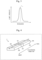
- FIG. 3 is a graph illustrating the characteristics of a reflection spectrum obtained in the FBG portion 102 of FIG. 2 .
- a wavelength at which the light intensity of the obtained reflection spectrum is maximized is called Bragg wavelength ⁇ b .
- the relation among the Bragg wavelength ⁇ b , the period A, and the refraction index n is represented by Expression (1) below.
- ⁇ b 2 n ⁇
- C T and C ⁇ are coefficients for temperature and strain.
- Strain can be measured by compensating for the effect of temperature from the rate of change ⁇ b of the Bragg wavelength ⁇ b .
- a light spectrum analyzer a wavemeter based on a Fabry-Perot interferometer, or the like is used, for example.
- gauge carrier as another component of the optical fiber displacement sensor according to the present embodiment is described.
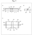
- FIGS. 4 and 5 illustrate an optical fiber displacement sensor 1 according to the present embodiment.
- FIG. 4 is a perspective view illustrating the optical fiber displacement sensor 1 according to the present embodiment.
- Each of the split regions 202 has a stiffness different from that of the center region 201.
- a total length of the longitudinal lengths of the two split regions 202 is greater than the longitudinal length of the center region 201.
- front means the direction in which incident light travels straight in the optical fiber 100.
- front and back are relative, either direction may be defined as front.
- the two split regions 202 each have an affixing portion 203 at an end away from the center region 201.
- the center region 201 and the split regions 202 are fixed at a contact surface 204 in a longitudinal cross section.
- the center region 201 and the split regions 202 are fixed by adhesion with adhesive 211, for example.
- adhesive force can be increased.
- optical fiber 100 it is also possible to fix the optical fiber 100 to the gauge carrier 200 with the optical fiber 100 being pre-tensioned. By pre-tensioning the optical fiber 100, measurement of strain in a direction of compression becomes possible.
- the optical fiber displacement sensor 1 is fixed to the object under measurement 300 by the whole or only part of the affixing portion 203 provided on the gauge carrier 200.
- the optical fiber displacement sensor 1 and the object under measurement 300 are fixed together by adhesion with affixing adhesive 301, for example.
- the deformation is transmitted to the gauge carrier 200 attached to the object under measurement 300.
- the stiffness of the split regions 202 can be made higher than the stiffness of the center region 201.
- the center region 201 is easier to deform than the split regions 202 and deformation of the center region 201 is larger than the deformation of the split regions 202.
- a magnification factor ⁇ of strain in the center region 201 with respect to strain in the object under measurement 300 will be Expression (3) below.
- FORMULA 1 ⁇ 1 + l 2 l 1 / 1 + E 1 A 1 E 2 A 2 ⁇ l 2 l 1
- the magnification factor ⁇ 0 can be 10, for example.
- the length of one of the split regions 202 is indicated as x and the length of the other is indicated as l 2 -x.
- the optical fiber displacement sensor 1 can be miniaturized without changing the width of the gauge carrier 200.
- SUS304 can be used as the material of the split regions 202 and epoxy resin can be used as the material of the center region 201. Since the elastic modulus of SUS304 (193 GPa) is about 100 times that of epoxy resin (2.4 GPa), a large stiffness difference can be obtained without changing the cross-sectional shape of the split regions 202.
- the gauge carrier 200 can be shaped such that it is 5 mm in width, 2 mm in height, and 10 mm in length (l 1 ) in the center region 201, and is 5 mm in width, 2 mm in height, and 140 mm in length (12) in the split regions 202.
- the magnification factor ⁇ of strain in the center region 201 relative to strain in the object under measurement 300 is about 12.8 times according to Expression (3). As a result, a small-sized optical fiber displacement sensor 1 with high strain detection sensitivity can be realized.
- the gauge carrier 200 and the optical fiber displacement sensor 1 that can effectively improve or suppress strain detection sensitivity can be realized.
- the optical fiber displacement sensor 1 that can be disposed in a narrow portion can be realized as well.
- the optical fiber displacement sensor 1 is composed of the optical fiber 100 having the gauge portion 101 and the gauge carrier 200 holding the optical fiber 100.
- the gauge carrier 200 is formed of the two split regions 202 and the center region 201 lying between the split regions 202 and having a different stiffness than that of split regions 202, where the total longitudinal length of the split regions 202 is greater than the longitudinal length of the center region 201.
- strain that occurs in the gauge portion 101 of the optical fiber 100 can be amplified or suppressed to improve or suppress strain detection sensitivity.
- the optical fiber displacement sensor 1 according to the present embodiment can also be disposed in a narrow portion.
- the grating length (the length of the gauge portion 101) has been described as being about 5 mm, other grating lengths may be used as long as light is sufficiently reflected.
- grating lengths such as 1 mm, 2 mm, 10 mm, and 25 mm may be used.
- the optical fiber displacement sensor 1 requires only that the stiffness of the split regions 202 and the stiffness of the center region 201 are different from each other.
- the stiffness of the split regions 202 is lower than the stiffness of the center region 201, strain in the center region 201 can be suppressed. This enables strain to be measured without breakage of the optical fiber 100 even when deformation of the object under measurement 300 is large.
- the way of fixation of the gauge carrier 200 and the optical fiber 100 and the way of fixation of the center region 201 and the split regions 202 have been described as adhesion with the adhesive 211.
- Other methods may be used as long as the gauge carrier 200 and the optical fiber 100 as well as the center region 201 and the split regions 202 are fixed to each other. For example, joint fittings, joints, and the like may be used.
- acrylic-based, epoxy-based, silicon-based, phenolic-based, polyethylene-based, polyimide-based, urethane-based, or polyurethane-based adhesive and the like can be used, for example.
- Conditions for hardening the adhesive 211 vary depending on the adhesive 211 used.
- grinding with abrasive paper is performed as pretreatment on a fixation surface.
- grinding with abrasive paper grinding with abrasive cloth, a wire brush, sand blasting, and the like may be performed.
- chemical treatment, primer treatment, ultraviolet irradiation treatment, plasma treatment, and the like may also be performed.
- the amplification ⁇ 0 of strain has been described as being 10, other amplification may be used in accordance with strain that is expected in the object under measurement 300.
- amplification such as 2, 3, 5, 25, 50, and 100 may be used.
- the center region 201 and the split regions 202 may also be different in thicknesses. In this case, the two split regions 202 are of the same thickness.
- SUS304 is used as the material of the split regions 202 and epoxy resin is used as the material of the center region 201.
- Materials other than SUS304 and epoxy resin may be used.
- silicon, polyimide resin, fluororesin, nylon resin, chloroprene rubber, silicone rubber, stainless steel, aluminum alloy, superinvar, and the like can be used.
- FIG. 7 is a perspective view illustrating the optical fiber displacement sensor 1 according to Embodiment 2.
- FIG. 8 is a side view illustrating the optical fiber displacement sensor 1.
- (b) of FIG. 8 is a front view illustrating the optical fiber displacement sensor 1.
- the cross sectional shape of the gauge carrier 200 according to Embodiment 1 is a rectangle.
- the cross sectional shape of the gauge carrier 200 according to Embodiment 2 is a hollow closed cross section. That is, while each of the center region 201 and the split regions 202 is a plate-shaped body in Embodiment 1, each of the center region 201 and the split regions 202 is a closed-section hollow circular cylinder in Embodiment 2.
- the center region 201 and the two split regions 202 are fixed at the contact surface 204 with adhesive, for example.
- each of the center region 201 and the split regions 202 has a hole 206 for holding the optical fiber 100.
- the hole 206 is provided substantially in the centers of the center region 201 and the split regions 202.
- the optical fiber 100 is inserted into the hole 206.
- a part of the optical fiber 100 including the gauge portion 101 is fixed on an inner surface (in the hole 206) of the center region 201 of the gauge carrier 200.
- the dimensions of the gauge carrier 200 according to Embodiment 2 can be the following.
- the outer diameter of the center region 201 can be 3 mm
- the inner diameter can be 0.4 mm
- the length (l 1 ) can be 10 mm.
- the outer diameter of the split regions 202 can be 3 mm
- the inner diameter can be 0.4 mm
- the length (12) can be 140 mm.
- the magnification factor ⁇ of strain in the center region 201 relative to strain in the object under measurement 300 is about 12.8 times according to Expression (3).
- Other structures are similar to Embodiment 1.
- the optical fiber displacement sensor 1 according to Embodiment 2 thereby can provide an effect of being easily attachable to a curved shape such as a cylinder, in addition to similar effects to Embodiment 1.
- FIGS. 10 and 11 illustrate the optical fiber displacement sensor 1 according to Embodiment 3.
- FIG. 11 is a front view illustrating the optical fiber displacement sensor 1 according to Embodiment 3.
- the split region 202 that is positioned in the back of the center region 201 is a back part of the middle part of the inner columnar body 207 and the outer columnar body 208 covering the back part.
- the shape of the gauge carrier 200 according to the present embodiment is substantially cylindrical. That is, in the present embodiment, the inner columnar body 207 and the outer columnar bodies 208 are each a hollow circular cylinder.
- the inner columnar body 207 is formed of two members as illustrated in FIGS. 10 and 11 .
- the two members forming the inner columnar body 207 will be each referred to as component member 217 hereinafter.
- the optical fiber displacement sensor 1 according to Embodiment 3 is composed of the inner columnar body 207 located in the entire areas of the split regions 202 and the center region 201, and the outer columnar bodies 208 located only in the split regions 202, such that the split regions 202 are double-structured.
- the inner columnar body 207 may be initially integrally formed without being sectioned into the two component members 217.
- Embodiment 4 a method of manufacturing the optical fiber displacement sensor 1 illustrated in Embodiments 1 to 3 is described.
- FIG. 12 illustrates the method of manufacturing the optical fiber displacement sensor 1 according to Embodiment 4.
- the gauge carrier 200 is manufactured.
- adhesive 211 is applied to contact surfaces 210 of the two component members 217 with the outer columnar bodies 208.
- the gauge carrier 200 and the optical fiber 100 are combined to manufacture the optical fiber displacement sensor 1.
- adhesive 211 is applied to the portions of the two component members 217 to which the optical fiber 100 is to be fixed. That is, adhesive 211 is applied to the portions corresponding to the center region 201.
- the adhesive 211 is also applied to the contact surfaces 209 of the component members 217.
- pretreatment Prior to application of the adhesive 211, pretreatment may be performed on the surfaces to which the adhesive 211 is to be applied in order to improve adhesion.
- the pretreatment can be grinding processing with abrasive paper, for example.
- the component members 217 and the outer columnar bodies 208 are placed at a position where the contact surfaces 209 of the two component members 217 come into contact with each other. Then, in the state illustrated in (f) of FIG. 12 , the positional relation between the component members 217 and the outer columnar bodies 208 is maintained until the adhesive 211 has hardened.
- the positional relation between the component members 217 and the outer columnar bodies 208 may be maintained with the optical fiber 100 tensioned.
- the method of manufacturing the optical fiber displacement sensor 1 includes the first manufacturing step of manufacturing the gauge carrier 200 by combining the center region 201 with the split regions 202, and the second manufacturing step of manufacturing the optical fiber displacement sensor 1 by combining the gauge carrier 200 with the optical fiber 100.
- the optical fiber displacement sensor 1 illustrated in Embodiment 1 and the optical fiber displacement sensor 1 illustrated in Embodiment 2 can also be manufactured in a similar manner.
- the optical fiber displacement sensor 1 illustrated in Embodiment 1 can be manufactured in the following manner, for example.
- the optical fiber displacement sensor 1 illustrated in Embodiment 2 can be manufactured in the following manner, for example.
Landscapes
- Physics & Mathematics (AREA)
- General Physics & Mathematics (AREA)
- Length Measuring Devices By Optical Means (AREA)
- Optical Transform (AREA)
- Optical Fibers, Optical Fiber Cores, And Optical Fiber Bundles (AREA)
Abstract
Description
- The present invention relates to a gauge carrier for holding an optical fiber and an optical fiber displacement sensor including an optical fiber and the gauge carrier.
- For optical survey satellites, ability to capture high-resolution images with good legibility and stable image quality is desired. Accordingly, optical survey satellites are required to be capable of maintaining stable optical survey performance on their orbits over a long term. Realization of such an optical survey satellite necessitates a support structure with high dimensional stability and a sensor for assessing the stability of the support structure.
- As sensors to detect deformation and strain of an object, strain gauges with resistor have been widely used. Since this type of a strain gauge obtains an amount of strain based on change in electric resistance, measures against electromagnetic noise are necessary. Also, since individual sensors require wiring, installation and handling are cumbersome in measurement at multiple points. Furthermore, there has been a problem of difficulty in attaching a sensor to a narrow portion.
- Hence, optical fiber strain gauges equipped with optical fibers have been increasingly used in recent years. An optical fiber strain gauge does not require measures against electromagnetic noise because it obtains an amount of strain based on change in reflection and scattering states of light transmitting within an optical fiber. The optical fiber strain gauges also facilitate multi-point measurement since a large number of measurement points can be set on a single optical fiber. Further, since optical fiber strain gauges are smaller in size than electric strain gauges, they also can be disposed in narrow portions.
- Additionally, by using a gauge carrier for holding an optical fiber strain gauge, an effect that cannot be obtained with an optical fiber strain gauge alone can be achieved as well.
-
Patent Literature 1 discloses an optical fiber strain sensor. - The optical fiber strain sensor of
Patent Literature 1 includes a gauge carrier which has a constricted portion and varies in longitudinal cross section, and an optical fiber strain gauge that uses FBG (Fiber Bragg Gratings). In the optical fiber strain sensor ofPatent Literature 1, the FBG portion of the optical fiber strain gauge is placed at the constricted portion of the gauge carrier. - Patent Literature 1:
JP 2008-134 155 A - In the technique disclosed in
Patent Literature 1, strain of the FBG portion manifests itself distinctly and strain detection sensitivity can be improved because the FBG portion of the optical fiber strain gauge is configured to be placed at the constricted portion of the gauge carrier. It is also possible to decrease the strain detection sensitivity by increasing the width of the gauge carrier, instead of a constricted portion. - However, the optical fiber strain sensor of
Patent Literature 1 has a problem of being unable to effectively improve or suppress the strain detection sensitivity for some shapes of the gauge carrier. - A major object of the present invention is to solve the aforementioned problem. More specifically, an object of the present invention is to allow the strain detection sensitivity to be effectively improved or suppressed.
- A gauge carrier according to the present invention to hold an optical fiber which has a gauge portion of a predefined length used for detection of strain, provided in one axial part thereof, the gauge carrier includes:
- a first holding portion which has a predefined stiffness and holds the gauge portion, wherein a length in a longitudinal direction of the gauge carrier is equal to or greater than a length of the gauge portion; and
- two second holding portions, wherein each of the second holding portions has a stiffness different from the stiffness of the first holding portion, a total length of lengths of the respective second holding portions in the longitudinal direction of the gauge carrier is greater than the length of the first holding portion in the longitudinal direction of the gauge carrier, one of the second holding portions is positioned in front of the first holding portion and holds a part of the optical fiber that is in front of the gauge portion, and another is positioned in back of the first holding portion and holds a part of the optical fiber that is in back of the gauge portion.
- According to the present invention, strain detection sensitivity can be effectively improved or suppressed.
-
- FIG. 1
- illustrates an optical fiber according to
Embodiment 1. - FIG. 2
- illustrates an FBG portion in the optical fiber according to
Embodiment 1. - FIG. 3
- illustrates the characteristics of a reflection spectrum obtained in the FBG portion according to
Embodiment 1. - FIG. 4
- is a perspective view illustrating an optical fiber displacement sensor according to
Embodiment 1. - FIG. 5
- is a side view, a front view, and a bottom view illustrating the optical fiber displacement sensor according to
Embodiment 1. - FIG. 6
- illustrates the optical fiber displacement sensor according to
Embodiment 1 as attached to an object under measurement. - FIG. 7
- is a perspective view illustrating an optical fiber displacement sensor according to Embodiment 2.
- FIG. 8
- is a side view and a front view illustrating the optical fiber displacement sensor according to Embodiment 2.
- FIG. 9
- illustrates installation of the optical fiber displacement sensor according to Embodiment 2 on a curved surface.
- FIG. 10
- is a perspective view illustrating an optical fiber displacement sensor according to Embodiment 3.
- FIG. 11
- is a side view and a front view illustrating the optical fiber displacement sensor according to Embodiment 3.
- FIG. 12
- illustrates manufacturing steps of an optical fiber displacement sensor according to Embodiment 4.
- Gauge carriers and optical fiber displacement sensors according to embodiments will be now described in detail with reference to the drawings. In description of the drawings, the same or corresponding portions are denoted with the same reference characters and overlapping descriptions are omitted.
- As noted above, the technique of
Patent Literature 1 has a problem of being unable to effectively improve or suppress strain detection sensitivity for some shapes of the gauge carrier. In addition, the technique ofPatent Literature 1 has a problem that the gauge carrier is large relative to an optical fiber and cannot be disposed in a narrow portion. - In view of these problems, the present embodiment describes a gauge carrier and an optical fiber displacement sensor that can effectively improve or suppress strain detection sensitivity and can be disposed in a narrow portion.
- First, an optical fiber as a component of the optical fiber displacement sensor according to the present embodiment is described.
- Optical fibers include multi-point optical fibers and distributed optical fibers. In a multi-point optical fiber, physical quantities are measured at one or more points within the single optical fiber. In the distributed optical fiber, physical quantities are continuously measured in the single optical fiber. In the multi-point optical fiber, one or more points serve as gauge portions. By contrast, for the distributed optical fiber, the entire optical fiber serves as a gauge portion. The gauge portion is a part that is used for detection of a physical quantity (specifically, strain).
- In measurement of physical quantities with an optical fiber, the physical quantity is calculated on the basis of a frequency change in reflected light or scattered light at a measurement location. For the reflected light, reflected light at an FBG (Fiber Bragg Gratings) portion provided in the optical fiber is used, for example. For the scattered light, Rayleigh scattered light, Brillouin scattered light, Raman scattered light, and the like are used, for example.
-
FIG. 1 illustrates anoptical fiber 100 according to the present embodiment. - The
optical fiber 100 according to the present embodiment is the multi-point optical fiber. - The
optical fiber 100 includes acore 103, a clad 104 covering an outer circumference of thecore 103, and acoating portion 105 covering an outer circumference of the clad 104. Agauge portion 101 is also provided in a part of thecore 103. That is to say, thegauge portion 101 is provided in one axial part of theoptical fiber 100. Specifically, thegauge portion 101 is positioned in thecore 103 over a range of about 5 mm in an axis direction of theoptical fiber 100. As mentioned above, thegauge portion 101 is a part used for detection of strain. - A diameter of the
coating portion 105 is 250 µm, for example. A diameter of the clad 104 is 125 µm, for example. A diameter of thecore 103 is 8 µm, for example. - Material of which the
coating portion 105 is formed can include acrylate resin, polyimide resin, lead, aluminum alloy, gold, and the like, for example. -
FIG. 2 illustrates details of thecore 103. - As illustrated in
FIG. 2 , thecore 103 is provided with anFBG portion 102 as thegauge portion 101. That is, in theoptical fiber 100 according to the present embodiment, theFBG portion 102 is used as thegauge portion 101. - The
FBG portion 102 is a portion in which refraction index modulation has been applied to thecore 103 at period A. For a method of forming the refraction index modulation, an approach that irradiates the core 103 with a laser beam using a phase mask is used, for example. When wide band light is incident on theoptical fiber 100, narrow band light corresponding to the period A and refraction index n of theFBG portion 102 is reflected in theFBG portion 102. -
FIG. 3 is a graph illustrating the characteristics of a reflection spectrum obtained in theFBG portion 102 ofFIG. 2 . A wavelength at which the light intensity of the obtained reflection spectrum is maximized is called Bragg wavelength λb. The relation among the Bragg wavelength λb, the period A, and the refraction index n is represented by Expression (1) below.
- The period A varies with a temperature T of the
FBG portion 102 and strain ε that occurs in theFBG portion 102. A rate of change Δλb in the Bragg wavelength λb represented by Expression (1) is approximated by Expression (2) below.
- Here, CT and Cε are coefficients for temperature and strain.
- Strain can be measured by compensating for the effect of temperature from the rate of change Δλb of the Bragg wavelength λb. For an instrument for measuring the reflection spectrum, a light spectrum analyzer, a wavemeter based on a Fabry-Perot interferometer, or the like is used, for example.
- Next, the gauge carrier as another component of the optical fiber displacement sensor according to the present embodiment is described.
-
FIGS. 4 and5 illustrate an opticalfiber displacement sensor 1 according to the present embodiment. -
FIG. 4 is a perspective view illustrating the opticalfiber displacement sensor 1 according to the present embodiment. - (a) of
FIG. 5 is a side view of the opticalfiber displacement sensor 1. (b) ofFIG. 5 is a front view of the opticalfiber displacement sensor 1. (c) ofFIG. 5 is a bottom view of the opticalfiber displacement sensor 1. - A
gauge carrier 200 is composed of onecenter region 201 and two splitregions 202. Each of thecenter region 201 and thesplit regions 202 is a plate-shaped body. - The
center region 201 corresponds to a first holding portion. Thesplit regions 202 correspond to second holding portions. - The
center region 201 lies between thesplit regions 202. - At least one
gauge portion 101 of theoptical fiber 100 is disposed so as to be fixed on thecenter region 201 and functions as a sensor portion. Thecenter region 201 holds thegauge portion 101. - A length of the
center region 201 in a longitudinal direction of the gauge carrier 200 (the axis direction of the optical fiber 100) is equal to or greater than a length of thegauge portion 101. The longitudinal direction of thegauge carrier 200 will be referred to just as the longitudinal direction hereinafter. - Each of the
split regions 202 has a stiffness different from that of thecenter region 201. - A total length of the longitudinal lengths of the two split
regions 202 is greater than the longitudinal length of thecenter region 201. - One of the
split regions 202 is positioned in front of thecenter region 201 to hold a part of theoptical fiber 100 that is in front of thegauge portion 101. Theother split region 202 is positioned in the back of thecenter region 201 to hold a part of theoptical fiber 100 that is in the back of thegauge portion 101. - In the present embodiment, front means the direction in which incident light travels straight in the
optical fiber 100. As front and back are relative, either direction may be defined as front. - The two split
regions 202 each have an affixingportion 203 at an end away from thecenter region 201. - The
center region 201 and thesplit regions 202 are fixed at acontact surface 204 in a longitudinal cross section. Thecenter region 201 and thesplit regions 202 are fixed by adhesion withadhesive 211, for example. By applying processing such as grinding with abrasive paper to the respective contact surfaces 204 of thecenter region 201 and thesplit regions 202, adhesive force can be increased. - The
gauge carrier 200 may also have agroove 205 provided in a portion where theoptical fiber 100 is installed for better installation of theoptical fiber 100. - That is, as illustrated in (b) of
FIG. 5 , each of thecenter region 201 and thesplit regions 202 may have thegroove 205 in a longitudinal direction for holding theoptical fiber 100. - A part of the
optical fiber 100 including thegauge portion 101 is fixed to thecenter region 201 of thegauge carrier 200. Thecenter region 201 and theoptical fiber 100 are fixed by adhesion with the adhesive 211, for example. By applying processing such as grinding with abrasive paper to the part of thecenter region 201 where theoptical fiber 100 is to be fixed, adhesive force can be increased. - The
optical fiber 100 may or may not be fixed with thesplit regions 202. However, since the state of fixation between theoptical fiber 100 and thesplit regions 202 can affect the strain detection accuracy in thegauge portion 101, theoptical fiber 100 is preferably not fixed to (is preferably separate from) thesplit regions 202. - It is also possible to fix the
optical fiber 100 to thegauge carrier 200 with theoptical fiber 100 being pre-tensioned. By pre-tensioning theoptical fiber 100, measurement of strain in a direction of compression becomes possible. -
FIG. 6 illustrates the opticalfiber displacement sensor 1 as attached to an object undermeasurement 300. - As illustrated in
FIG. 6 , the opticalfiber displacement sensor 1 is fixed to the object undermeasurement 300 by the whole or only part of the affixingportion 203 provided on thegauge carrier 200. The opticalfiber displacement sensor 1 and the object undermeasurement 300 are fixed together by adhesion with affixing adhesive 301, for example. - When the object under
measurement 300 deforms in response to load, heat, or the like, the deformation is transmitted to thegauge carrier 200 attached to the object undermeasurement 300. As thecenter region 201 and thesplit regions 202 of thegauge carrier 200 are of different stiffnesses, a difference in the amounts of strain in the respective regions will occur. Specifically, the stiffness of thesplit regions 202 can be made higher than the stiffness of thecenter region 201. In this case, thecenter region 201 is easier to deform than the splitregions 202 and deformation of thecenter region 201 is larger than the deformation of thesplit regions 202. - As a result, the strain that occurs in the
center region 201 is larger than the strain that occurs in the object undermeasurement 300. That is, strain is amplified in thecenter region 201. Since thegauge portion 101 of theoptical fiber 100 is fixed to thecenter region 201, a strain comparable to the strain in thecenter region 201 occurs in theoptical fiber 100. Accordingly, a strain larger than in the object undermeasurement 300 occurs in thegauge portion 101 of theoptical fiber 100, which can improve the detection sensitivity. - When the stiffness of the
center region 201 is indicated as E1A1, the stiffness of thesplit regions 202 is indicated as E2A2, the longitudinal length of thecenter region 201 is indicated as l1, and the total longitudinal length of thesplit regions 202 is indicated as l2, a magnification factor α of strain in thecenter region 201 with respect to strain in the object undermeasurement 300 will be Expression (3) below.
FORMULA 1
- Since, on the
gauge carrier 200, the total longitudinal length of thesplit regions 202 is greater than the longitudinal length of the center region 201 (l1 < l2), a strain amplification effect of twofold or more can be achieved by making the stiffness E2A2 of thesplit regions 202 sufficiently high relative to the stiffness E1A1 of thecenter region 201. In order to amplify strain to a certain magnification factor α0 or higher, the stiffness E1A1 of thecenter region 201, the stiffness E2A2 of thesplit regions 202, the length l1 of thecenter region 201, and the total length l2 of thesplit regions 202 are set such that Expression (4) below is satisfied.
FORMULA 2
- The magnification factor α0 can be 10, for example.
- In (a) of
FIG. 5 , the length of one of thesplit regions 202 is indicated as x and the length of the other is indicated as l2-x. - A way of obtaining a difference between the stiffness of the
center region 201 and the stiffness of thesplit regions 202 can be using different materials in thesplit regions 202 and thecenter region 201, for example. In this case, the two splitregions 202 are of the same material. - By doing so, the optical
fiber displacement sensor 1 can be miniaturized without changing the width of thegauge carrier 200. Specifically, SUS304 can be used as the material of thesplit regions 202 and epoxy resin can be used as the material of thecenter region 201. Since the elastic modulus of SUS304 (193 GPa) is about 100 times that of epoxy resin (2.4 GPa), a large stiffness difference can be obtained without changing the cross-sectional shape of thesplit regions 202. Thegauge carrier 200 can be shaped such that it is 5 mm in width, 2 mm in height, and 10 mm in length (l1) in thecenter region 201, and is 5 mm in width, 2 mm in height, and 140 mm in length (12) in thesplit regions 202. In this case, the magnification factor α of strain in thecenter region 201 relative to strain in the object undermeasurement 300 is about 12.8 times according to Expression (3). As a result, a small-sized opticalfiber displacement sensor 1 with high strain detection sensitivity can be realized. - According to the present embodiment, the
gauge carrier 200 and the opticalfiber displacement sensor 1 that can effectively improve or suppress strain detection sensitivity can be realized. According to the present embodiment, the opticalfiber displacement sensor 1 that can be disposed in a narrow portion can be realized as well. - As described above, the optical
fiber displacement sensor 1 according to the present embodiment is composed of theoptical fiber 100 having thegauge portion 101 and thegauge carrier 200 holding theoptical fiber 100. - The
gauge carrier 200 is formed of the two splitregions 202 and thecenter region 201 lying between thesplit regions 202 and having a different stiffness than that ofsplit regions 202, where the total longitudinal length of thesplit regions 202 is greater than the longitudinal length of thecenter region 201. - The
gauge portion 101 of theoptical fiber 100 is fixed on thecenter region 201, and two splitregions 202 of thegauge carrier 200 each have the affixingportion 203 at the end away from thecenter region 201. When deformation occurs in the object undermeasurement 300 fixed by the affixingportion 203 provided on thegauge carrier 200, a difference occurs in the amounts of strain in thecenter region 201 and in thesplit regions 202 of thegauge carrier 200 because they have different stiffnesses. - Thus, strain that occurs in the
gauge portion 101 of theoptical fiber 100 can be amplified or suppressed to improve or suppress strain detection sensitivity. The opticalfiber displacement sensor 1 according to the present embodiment can also be disposed in a narrow portion. - Although, in the present embodiment, the grating length (the length of the gauge portion 101) has been described as being about 5 mm, other grating lengths may be used as long as light is sufficiently reflected. For example, grating lengths such as 1 mm, 2 mm, 10 mm, and 25 mm may be used.
- In the present embodiment, an instance where the stiffness of the
split regions 202 is higher than the stiffness of thecenter region 201 and strain is amplified, has been described. However, the opticalfiber displacement sensor 1 requires only that the stiffness of thesplit regions 202 and the stiffness of thecenter region 201 are different from each other. When the stiffness of thesplit regions 202 is lower than the stiffness of thecenter region 201, strain in thecenter region 201 can be suppressed. This enables strain to be measured without breakage of theoptical fiber 100 even when deformation of the object undermeasurement 300 is large. - In the present embodiment, the way of fixation of the
gauge carrier 200 and theoptical fiber 100 and the way of fixation of thecenter region 201 and thesplit regions 202 have been described as adhesion with the adhesive 211. Other methods may be used as long as thegauge carrier 200 and theoptical fiber 100 as well as thecenter region 201 and thesplit regions 202 are fixed to each other. For example, joint fittings, joints, and the like may be used. - For the adhesive 211, acrylic-based, epoxy-based, silicon-based, phenolic-based, polyethylene-based, polyimide-based, urethane-based, or polyurethane-based adhesive and the like can be used, for example. Conditions for hardening the adhesive 211 vary depending on the adhesive 211 used.
- In the present embodiment, an instance where grinding with abrasive paper is performed as pretreatment on a fixation surface has been described. Instead of grinding with abrasive paper, grinding with abrasive cloth, a wire brush, sand blasting, and the like may be performed. Apart from grinding, chemical treatment, primer treatment, ultraviolet irradiation treatment, plasma treatment, and the like may also be performed.
- Although, in the present embodiment, the amplification α0 of strain has been described as being 10, other amplification may be used in accordance with strain that is expected in the object under
measurement 300. For example, amplification such as 2, 3, 5, 25, 50, and 100 may be used. - Although the present embodiment uses different materials in the
center region 201 and thesplit regions 202 as a way of obtaining a difference between the stiffness of thecenter region 201 and the stiffness of thesplit regions 202, thecenter region 201 and thesplit regions 202 may also be different in thicknesses. In this case, the two splitregions 202 are of the same thickness. - Since a different thickness leads to a different cross sectional area, a difference in stiffness can be obtained even when the same material is used for the
center region 201 and thesplit regions 202. - In the present embodiment, an instance where SUS304 is used as the material of the
split regions 202 and epoxy resin is used as the material of thecenter region 201, has been described. Materials other than SUS304 and epoxy resin may be used. For example, silicon, polyimide resin, fluororesin, nylon resin, chloroprene rubber, silicone rubber, stainless steel, aluminum alloy, superinvar, and the like can be used. - In
Embodiment 1, an instance that uses asingle center region 201 has been described. However, thecenter region 201 consisting of two or more members may be used as long as anintegral center region 201 is obtained after being fixed to theoptical fiber 100 and thesplit regions 202. In this case, the two or more members are fixed such as by adhesive to create anintegral center region 201. -
FIGS. 7 and8 illustrate the opticalfiber displacement sensor 1 according to Embodiment 2. -
FIG. 7 is a perspective view illustrating the opticalfiber displacement sensor 1 according to Embodiment 2. - (a) of
FIG. 8 is a side view illustrating the opticalfiber displacement sensor 1. (b) ofFIG. 8 is a front view illustrating the opticalfiber displacement sensor 1. - (a) of
FIG. 9 illustrates an example where the opticalfiber displacement sensor 1 according toEmbodiment 1 is disposed on a curved surface. (b) ofFIG. 9 illustrates an example where the opticalfiber displacement sensor 1 according to Embodiment 2 is disposed on a curved surface. - The cross sectional shape of the
gauge carrier 200 according toEmbodiment 1 is a rectangle. By contrast, the cross sectional shape of thegauge carrier 200 according to Embodiment 2 is a hollow closed cross section. That is, while each of thecenter region 201 and thesplit regions 202 is a plate-shaped body inEmbodiment 1, each of thecenter region 201 and thesplit regions 202 is a closed-section hollow circular cylinder in Embodiment 2. Thecenter region 201 and the two splitregions 202 are fixed at thecontact surface 204 with adhesive, for example. - In Embodiment 2, each of the
center region 201 and thesplit regions 202 has ahole 206 for holding theoptical fiber 100. Thehole 206 is provided substantially in the centers of thecenter region 201 and thesplit regions 202. - Then, in Embodiment 2, the
optical fiber 100 is inserted into thehole 206. A part of theoptical fiber 100 including thegauge portion 101 is fixed on an inner surface (in the hole 206) of thecenter region 201 of thegauge carrier 200. - Being thus configured, the
gauge carrier 200 according to Embodiment 2 is easy to attach to a curved shape such as a cylinder as illustrated in (b) ofFIG. 9 . - The dimensions of the
gauge carrier 200 according to Embodiment 2 can be the following. For example, the outer diameter of thecenter region 201 can be 3 mm, the inner diameter can be 0.4 mm, and the length (l1) can be 10 mm. The outer diameter of thesplit regions 202 can be 3 mm, the inner diameter can be 0.4 mm, and the length (12) can be 140 mm. - If SUS304 is used as the material of the
split regions 202 and epoxy resin is used as the material of thecenter region 201 as inEmbodiment 1, the magnification factor α of strain in thecenter region 201 relative to strain in the object undermeasurement 300 is about 12.8 times according to Expression (3). Other structures are similar toEmbodiment 1. - As described above, in the optical
fiber displacement sensor 1 according to Embodiment 2, the cross sectional shape of thegauge carrier 200 is a hollow closed cross section. - The optical
fiber displacement sensor 1 according to Embodiment 2 thereby can provide an effect of being easily attachable to a curved shape such as a cylinder, in addition to similar effects toEmbodiment 1. - Although, in the present embodiment, the hollow closed cross section of the
gauge carrier 200 has been described as being substantially circular, it may also be substantially semi-circular, substantially sector, substantially elliptical, substantially rectangular, substantially square, and the like, instead of being substantially circular. That is, each of thecenter region 201 and thesplit regions 202 may also be any of a closed-section hollow half cylinder, a closed-section hollow sector cylinder, a closed-section hollow elliptical cylinder, and a closed-section hollow square column. - Although, in the present embodiment, an instance where each of the
center region 201 and thesplit regions 202 is a closed-section hollow circular cylinder has been described, each of thecenter region 201 and thesplit regions 202 may be a solid columnar body with thehole 206 therethrough. -
FIGS. 10 and11 illustrate the opticalfiber displacement sensor 1 according to Embodiment 3. -
FIG. 10 is a perspective view illustrating the opticalfiber displacement sensor 1 according to Embodiment 3. - (a) of
FIG. 11 is a side view illustrating the opticalfiber displacement sensor 1 according to Embodiment 3. - (b) of
FIG. 11 is a front view illustrating the opticalfiber displacement sensor 1 according to Embodiment 3. - In
Embodiments 1 and 2, a structure where thecenter region 201 and thesplit regions 202 of thegauge carrier 200 are fixed together at the contact surfaces 204 in longitudinal cross sections has been described. In contrast, thegauge carrier 200 according to Embodiment 3 consists of a hollow innercolumnar body 207 located in the entire areas of thecenter region 201 and thesplit regions 202 and separate hollow outercolumnar bodies 208 located only in thesplit regions 202, such that thesplit regions 202 are double-structured. - In the present embodiment, the
center region 201 is a middle part of the innercolumnar body 207. - The
split region 202 that is positioned in front of thecenter region 201 is a front part of the middle part of the innercolumnar body 207 and the outercolumnar body 208 covering the front part. - The
split region 202 that is positioned in the back of thecenter region 201 is a back part of the middle part of the innercolumnar body 207 and the outercolumnar body 208 covering the back part. - Such a structure makes a breakage less likely to occur between the
center region 201 and thesplit regions 202 and also improves the manufacturability of the opticalfiber displacement sensor 1. - Also in the present embodiment, the stiffness of the
center region 201 and the stiffness of thesplit regions 202 are different because the thickness of thecenter region 201 and the thickness of thesplit regions 202 are different. - In the present embodiment, the
optical fiber 100 is inserted into the innercolumnar body 207. A part of theoptical fiber 100 including thegauge portion 101 is fixed to the inner surface of the innercolumnar body 207 at the position of thecenter region 201. - As illustrated in
FIGS. 10 and11 , the shape of thegauge carrier 200 according to the present embodiment is substantially cylindrical. That is, in the present embodiment, the innercolumnar body 207 and the outercolumnar bodies 208 are each a hollow circular cylinder. - The inner diameter of the outer
columnar bodies 208 is larger than the outer diameter of the innercolumnar body 207. The innercolumnar body 207 is positioned on the inner surfaces of the outercolumnar bodies 208. - In the present embodiment, the inner
columnar body 207 is formed of two members as illustrated inFIGS. 10 and11 . The two members forming the innercolumnar body 207 will be each referred to ascomponent member 217 hereinafter. - In the example of
FIGS. 10 and11 , the innercolumnar body 207 is formed of thecomponent member 217 on the front side of the center of thecenter region 201 and thecomponent member 217 on the back side of the center of thecenter region 201. That is, the length of eachcomponent member 217 is half that of the innercolumnar body 207. Then, the twocomponent members 217 are fixed at acontact surface 209 during manufacture into an integral innercolumnar body 207. The twocomponent members 217 are fixed by adhesion withadhesive 211, for example. - In this manner, the
center region 201 in the present embodiment is sectioned into two parts in a direction perpendicular to the longitudinal direction. - The dimensions of the
gauge carrier 200 according to Embodiment 3 can be the following. For example, the outer diameter of the innercolumnar body 207 can be 1.5 mm, the inner diameter can be 0.4 mm, and the length can be 150 mm. The outer diameter of the outercolumnar body 208 can be 3.0 mm, the inner diameter can be 2.0 mm, and the length (l2) can be 100 mm. - When epoxy resin is used as the material of the inner
columnar body 207 and SUS304 is used as the material of the outercolumnar body 208, the magnification factor α of strain in thecenter region 201 relative to strain in the object undermeasurement 300 is about 12.7 times according to Expression (3). - Other structures are similar to
Embodiment 1. Other structures may also be similar to Embodiment 2. - As described above, the optical
fiber displacement sensor 1 according to Embodiment 3 is composed of the innercolumnar body 207 located in the entire areas of thesplit regions 202 and thecenter region 201, and the outercolumnar bodies 208 located only in thesplit regions 202, such that thesplit regions 202 are double-structured. - The optical
fiber displacement sensor 1 according to Embodiment 3 thereby can provide an effect of a breakage being less likely to occur between thecenter region 201 and thesplit regions 202, in addition to similar effects toEmbodiment 1. Also, according to Embodiment 3, the manufacturability of the opticalfiber displacement sensor 1 can be improved. - Although, in Embodiment 3, a structure where the inner
columnar body 207 is formed of twocomponent members 217 and the twocomponent members 217 are connected during manufacture has been described, the innercolumnar body 207 may be initially integrally formed without being sectioned into the twocomponent members 217. - Also, the
center region 201 illustrated inEmbodiments 1 and 2 may be sectioned into two parts in a direction perpendicular to the longitudinal direction, like thecenter region 201 in Embodiment 3. - Next, as Embodiment 4, a method of manufacturing the optical
fiber displacement sensor 1 illustrated inEmbodiments 1 to 3 is described. -
FIG. 12 illustrates the method of manufacturing the opticalfiber displacement sensor 1 according to Embodiment 4. -
FIG. 12 illustrates a method of manufacturing the double-structured opticalfiber displacement sensor 1 composed of the innercolumnar body 207 and the outercolumnar bodies 208 according to Embodiment 3 as an example.FIG. 12 also illustrates an example of forming the innercolumnar body 207 by connecting the twocomponent members 217 as described in Embodiment 3. - The method of manufacture illustrated in
FIG. 12 is generally divided into a first manufacturing step and a second manufacturing step. - In the first manufacturing step, the
gauge carrier 200 is manufactured. - First, as illustrated in (a) of
FIG. 12 , adhesive 211 is applied to contactsurfaces 210 of the twocomponent members 217 with the outercolumnar bodies 208. - In (a) of
FIG. 12 , an instance where the adhesive 211 is only applied to the contact surfaces 210 on the outer radial surfaces of thecomponent members 217 is illustrated. Additionally or alternatively, the adhesive 211 may be applied to the inner radial surfaces of the outercolumnar bodies 208. - Prior to application of the adhesive 211, pretreatment may be performed on the contact surfaces 210 of the
component members 217 in order to improve adhesion. The pretreatment can be grinding processing with abrasive paper, for example. - Next, the
component members 217 are inserted into the outercolumnar bodies 208 as illustrated in (b) ofFIG. 12 , and thecomponent members 217 and the outercolumnar bodies 208 are placed at positions that align the ends of thecomponent members 217 with the ends of the outercolumnar bodies 208 as illustrated in (c) ofFIG. 12 . Then, in the state illustrated in (c) ofFIG. 12 , the positional relation between thecomponent members 217 and the outercolumnar bodies 208 is maintained until the adhesive 211 has hardened. - Next, in the second manufacturing step, the
gauge carrier 200 and theoptical fiber 100 are combined to manufacture the opticalfiber displacement sensor 1. - First, as illustrated in (d) of
FIG. 12 , theoptical fiber 100 is placed in thegauge carrier 200. Specifically, theoptical fiber 100 is passed into the twocomponent members 217. - Next, as illustrated in (e) of
FIG. 12 , adhesive 211 is applied to the portions of the twocomponent members 217 to which theoptical fiber 100 is to be fixed. That is, adhesive 211 is applied to the portions corresponding to thecenter region 201. - The adhesive 211 is also applied to the contact surfaces 209 of the
component members 217. - Prior to application of the adhesive 211, pretreatment may be performed on the surfaces to which the adhesive 211 is to be applied in order to improve adhesion. The pretreatment can be grinding processing with abrasive paper, for example.
- Then, as illustrated in (f) of
FIG. 12 , thecomponent members 217 and the outercolumnar bodies 208 are placed at a position where the contact surfaces 209 of the twocomponent members 217 come into contact with each other. Then, in the state illustrated in (f) ofFIG. 12 , the positional relation between thecomponent members 217 and the outercolumnar bodies 208 is maintained until the adhesive 211 has hardened. - In doing so, the positional relation between the
component members 217 and the outercolumnar bodies 208 may be maintained with theoptical fiber 100 tensioned. By fixing theoptical fiber 100 to thecomponent members 217 with theoptical fiber 100 pre-tensioned, measurement of strain in a direction of compression becomes possible. - When the adhesive 211 has hardened in the state of (f) of
FIG. 12 , the twocomponent members 217 becomes integral to form the innercolumnar body 207. As a result, the opticalfiber displacement sensor 1 is completed. - From the foregoing, the method of manufacturing the optical
fiber displacement sensor 1 according to the present embodiment includes the first manufacturing step of manufacturing thegauge carrier 200 by combining thecenter region 201 with thesplit regions 202, and the second manufacturing step of manufacturing the opticalfiber displacement sensor 1 by combining thegauge carrier 200 with theoptical fiber 100. - While the present embodiment described a method of manufacturing the optical
fiber displacement sensor 1 illustrated in Embodiment 3, the opticalfiber displacement sensor 1 illustrated inEmbodiment 1 and the opticalfiber displacement sensor 1 illustrated in Embodiment 2 can also be manufactured in a similar manner. - The optical
fiber displacement sensor 1 illustrated inEmbodiment 1 can be manufactured in the following manner, for example. - (1)
Adhesive 211 is applied to the twocontact surfaces 204 of thecenter region 201. - (2) The
split regions 202 are fixed to the two contact surfaces 204. - (3)
Adhesive 211 is applied to thegroove 205 in thecenter region 201. - (4) The
optical fiber 100 is placed in thegroove 205 of thecenter region 201 and the two split regions 202 (theoptical fiber 100 is fixed by the adhesive 211 in thegroove 205 of the center region 201). - The optical
fiber displacement sensor 1 illustrated in Embodiment 2 can be manufactured in the following manner, for example. - (1)
Adhesive 211 is applied to thehole 206 in thecenter region 201. - (2) The
optical fiber 100 is inserted into the hole 206 (theoptical fiber 100 is fixed by thehole 206 in the center region 201). - (3)
Adhesive 211 is applied to the twocontact surfaces 204 of thecenter region 201. - (4) The
optical fiber 100 is passed through thehole 206 in thesplit regions 202, fixing thesplit regions 202 to the two contact surfaces 204. - While
Embodiments 1 to 4 have been described above, two or more of these embodiments may be practiced in combination. - Alternatively, one of these embodiments may be practiced partially.
- Alternatively, two or more of these embodiments may be practiced in partial combination.
- Also, structures and procedures described in these embodiments may be modified as needed.
-
- 1: optical fiber displacement sensor
- 100: optical fiber
- 101: gauge portion
- 102: FBG portion
- 103: core
- 104: clad
- 105: coating portion
- 200: gauge carrier
- 201: center region
- 202: split region
- 203: affixing portion
- 204: contact surface
- 205: groove
- 206: hole
- 207: inner columnar body
- 208: outer columnar body
- 209: contact surface
- 210: contact surface
- 211: adhesive
- 217: component member
- 300: object under measurement
- 301: affixing adhesive
Claims (13)
- A gauge carrier to hold an optical fiber which has a gauge portion of a predefined length used for detection of strain, provided in one axial part thereof, the gauge carrier comprising:
a first holding portion which has a predefined stiffness and holds the gauge wherein a length in a longitudinal direction of the gauge carrier is equal to or greater than a length of the gauge portion; andtwo second holding portions, wherein each of the second holding portions has a stiffness different from the stiffness of the first holding portion, a total length of lengths of the respective second holding portions in the longitudinal direction of the gauge carrier is greater than the length of the first holding portion in the longitudinal direction of the gauge carrier, one of the second holding portions is positioned in front of the first holding portion and holds a part of the optical fiber that is in front of the gauge portion, and another is positioned in back of the first holding portion and holds a part of the optical fiber that is in back of the gauge portion. - The gauge carrier according to claim 1, wherein
the stiffness of each of the second holding portions is higher than the stiffness of the one holding portion. - The gauge carrier according to claim 1, wherein
each of the first holding portion and the second holding portions is a plate-shaped body having, in the longitudinal direction of the gauge carrier, a groove to hold the optical fiber. - The gauge carrier according to claim 1, wherein
each of the first holding portion and the second holding portions is a columnar body having a hole to hold the optical fiber. - The gauge carrier according to claim 4, wherein
each of the first holding portion and the second holding portions is any one of a circular cylinder, a half cylinder, a sector cylinder, an elliptical cylinder, and a square column. - The gauge carrier according to claim 1, whereinthe first holding portion is a middle part of an inner columnar body having a hole to hold the optical fiber,the second holding portion that is positioned in front of the first holding portion is composed of a front part of the middle part of the inner columnar body and an outer columnar body covering the front part, andthe second holding portion that is positioned in back of the first holding portion is composed of a back part of the middle part of the inner columnar body and an outer columnar body covering the back part.
- The gauge carrier according to claim 1, wherein
the second holding portions are of a same material as one another, while materials are different between each of the second holding portions and the first holding portion, thus making the stiffness of the second holding portions different from the stiffness of the first holding portion. - The gauge carrier according to claim 1, wherein
the second holding portions are of a same thickness as one another, while thicknesses are different between each of the second holding portions and the first holding portion, thus making the stiffness of the second holding portions different from the stiffness of the first holding portion. - The gauge carrier according to claim 1, wherein
when the stiffness of the first holding portion is indicated as E1A1, the stiffness of each of the second holding portions is indicated as E2A2, the length of the first holding portion in the longitudinal direction of the gauge carrier is indicated as l1, and the total length of the lengths of the respective second holding portions in the longitudinal direction of the gauge carrier is indicated as l2, a condition of Expression (1) is satisfied:
FORMULA 1
- The gauge carrier according to claim 1, wherein
the first holding portion is sectioned into two parts in a direction perpendicular to the longitudinal direction of the gauge carrier. - An optical fiber displacement sensor comprising:an optical fiber which has a gauge portion of a predefined length used for detection of strain, provided in one axial part thereof; anda gauge carrier to hold the optical fiber, whereinthe gauge carrier includesa first holding portion which has a predefined stiffness and holds the gauge portion, wherein a length in a longitudinal direction of the gauge carrier is equal to or greater than a length of the gauge portion, andtwo second holding portions, wherein each of the second holding portions has a stiffness different from the stiffness of the first holding portion, a total length of lengths of the respective second holding portions in the longitudinal direction of the gauge carrier is greater than the length of the first holding portion in the longitudinal direction of the gauge carrier, one of the second holding portions is positioned in front of the first holding portion and holds a part of the optical fiber that is in front of the gauge portion, and another is positioned in back of the first holding portion and holds a part of the optical fiber that is in back of the gauge portion, andthe optical fiber is fixed at least to the first holding portion.
- The optical fiber displacement sensor according to claim 11, wherein the optical fiber is fixed at least to the first holding portion with the optical fiber tensioned.
- A method of manufacturing an optical fiber displacement sensor including an optical fiber which has a gauge portion of a predefined length used for detection of strain, provided in one axial part thereof, and a gauge carrier to hold the optical fiber, the method comprising:a step of combining a first holding portion with two second holding portions to manufacture the gauge carrier,the first holding portion having a predefined stiffness and holding the gauge portion, wherein a length in a longitudinal direction of the gauge carrier is equal to or greater than a length of the gauge portion,
each of the second holding portions having a stiffness different from the stiffness of the first holding portion, wherein a total length of lengths of the respective second holding portions in the longitudinal direction of the gauge carrier is greater than the length of the first holding portion in the longitudinal direction of the gauge carrier, one of the second holding portions is positioned in front of the first holding portion and holds a part of the optical fiber that is in front of the gauge portion, and another is positioned in back of the first holding portion and holds a part of the optical fiber that is in back of the gauge portion; anda step of fixing the optical fiber at least to the first holding portion.
Applications Claiming Priority (1)
| Application Number | Priority Date | Filing Date | Title |
|---|---|---|---|
| PCT/JP2021/002392 WO2022157963A1 (en) | 2021-01-25 | 2021-01-25 | Gauge carrier, optical fiber displacement sensor, and production method for optical fiber displacement sensor |
Publications (2)
| Publication Number | Publication Date |
|---|---|
| EP4283251A1 true EP4283251A1 (en) | 2023-11-29 |
| EP4283251A4 EP4283251A4 (en) | 2024-03-06 |
Family
ID=80815893
Family Applications (1)
| Application Number | Title | Priority Date | Filing Date |
|---|---|---|---|
| EP21921071.3A Withdrawn EP4283251A4 (en) | 2021-01-25 | 2021-01-25 | GAUGE HOLDER, OPTICAL FIBER DISPLACEMENT SENSOR, AND METHOD FOR PRODUCING OPTICAL FIBER DISPLACEMENT SENSOR |
Country Status (4)
| Country | Link |
|---|---|
| US (1) | US20240053139A1 (en) |
| EP (1) | EP4283251A4 (en) |
| JP (1) | JP7016451B1 (en) |
| WO (1) | WO2022157963A1 (en) |
Family Cites Families (9)
| Publication number | Priority date | Publication date | Assignee | Title |
|---|---|---|---|---|
| JP2983018B1 (en) * | 1998-09-30 | 1999-11-29 | エヌ・ティ・ティ・アドバンステクノロジ株式会社 | Optical fiber sensor |
| KR100495416B1 (en) * | 2003-07-24 | 2005-06-16 | 이금석 | Fixer for Fiber Bragg Grating sensor |
| CN2646666Y (en) * | 2003-09-05 | 2004-10-06 | 刘育梁 | Sensitive Fiber Bragg Grating Strain Sensor |
| JP4073896B2 (en) * | 2004-05-26 | 2008-04-09 | 三菱電機株式会社 | Optical fiber sensor composite cable and optical fiber monitoring system net |
| JP4897445B2 (en) | 2006-11-28 | 2012-03-14 | 株式会社共和電業 | Optical fiber strain gauge |
| JP4868593B2 (en) * | 2007-04-29 | 2012-02-01 | 鹿島建設株式会社 | Optical fiber sensor |
| JP2012088155A (en) * | 2010-10-19 | 2012-05-10 | Hitachi Ltd | Measuring method using fbg sensor, and device thereof |
| JP6397369B2 (en) * | 2015-05-19 | 2018-09-26 | 株式会社東京測器研究所 | Displacement measuring system and displacement measuring method |
| NL2020872B1 (en) * | 2018-05-03 | 2019-11-12 | Fugro Tech Bv | Sensor assembly for monitoring an artifact |
-
2021
- 2021-01-25 WO PCT/JP2021/002392 patent/WO2022157963A1/en not_active Ceased
- 2021-01-25 JP JP2021530267A patent/JP7016451B1/en active Active
- 2021-01-25 US US18/267,456 patent/US20240053139A1/en active Pending
- 2021-01-25 EP EP21921071.3A patent/EP4283251A4/en not_active Withdrawn
Also Published As
| Publication number | Publication date |
|---|---|
| JP7016451B1 (en) | 2022-02-04 |
| EP4283251A4 (en) | 2024-03-06 |
| JPWO2022157963A1 (en) | 2022-07-28 |
| WO2022157963A1 (en) | 2022-07-28 |
| US20240053139A1 (en) | 2024-02-15 |
Similar Documents
| Publication | Publication Date | Title |
|---|---|---|
| US20030106379A1 (en) | System and method for measuring stress at an interface | |
| EP1816432A1 (en) | Fiber optic strain gage | |
| CA2676246C (en) | Transducer for measuring environmental parameters | |
| CA2334333A1 (en) | Optical fiber sensor | |
| US20110229099A1 (en) | Fiber optic cable | |
| EP3420306B1 (en) | Method and system for correcting for nonlinear twist response in optical shape sensing with spun multicore fibers | |
| JP2005055450A (en) | Optical fiber strain gauge | |
| US20120132008A1 (en) | Fiber optic load measurement device | |
| CN107328369A (en) | Fiber Bragg grating strain sensor | |
| US10627284B2 (en) | Optical-fibre sensor device | |
| EP2990756B1 (en) | Strain sensor and strain sensor installation method | |
| JP2005003609A (en) | Cantilever-like displacement conversion mechanism using fiber bragg grating | |
| JP4897445B2 (en) | Optical fiber strain gauge | |
| JP2000028456A (en) | Pressure detection unit | |
| EP4283251A1 (en) | Gauge carrier, optical fiber displacement sensor, and production method for optical fiber displacement sensor | |
| EP2990755A1 (en) | Strain sensor and manufacturing method for strain sensor | |
| JPS62273423A (en) | Measured value detector | |
| JP2003287451A (en) | Optical flow sensor | |
| EP3425343B1 (en) | Optical fiber sensor | |
| EP2875326A1 (en) | System and method for measuring torque | |
| JP6736044B2 (en) | Strain sensor and jig for mounting the strain sensor | |
| JP2019109057A (en) | Optical fiber sensor | |
| US4735103A (en) | Force sensor | |
| Zhang et al. | Experimental investigation on optical spectral deformation of embedded FBG sensors | |
| Zhang et al. | Fiber Bragg grating pressure sensor with enhanced sensitivity |
Legal Events
| Date | Code | Title | Description |
|---|---|---|---|
| STAA | Information on the status of an ep patent application or granted ep patent |
Free format text: STATUS: THE INTERNATIONAL PUBLICATION HAS BEEN MADE |
|
| PUAI | Public reference made under article 153(3) epc to a published international application that has entered the european phase |
Free format text: ORIGINAL CODE: 0009012 |
|
| STAA | Information on the status of an ep patent application or granted ep patent |
Free format text: STATUS: REQUEST FOR EXAMINATION WAS MADE |
|
| 17P | Request for examination filed |
Effective date: 20230718 |
|
| AK | Designated contracting states |
Kind code of ref document: A1 Designated state(s): AL AT BE BG CH CY CZ DE DK EE ES FI FR GB GR HR HU IE IS IT LI LT LU LV MC MK MT NL NO PL PT RO RS SE SI SK SM TR |
|
| A4 | Supplementary search report drawn up and despatched |
Effective date: 20240207 |
|
| RIC1 | Information provided on ipc code assigned before grant |
Ipc: G01D 5/353 20060101ALI20240201BHEP Ipc: G01B 11/16 20060101AFI20240201BHEP |
|
| DAV | Request for validation of the european patent (deleted) | ||
| DAX | Request for extension of the european patent (deleted) | ||
| GRAP | Despatch of communication of intention to grant a patent |
Free format text: ORIGINAL CODE: EPIDOSNIGR1 |
|
| STAA | Information on the status of an ep patent application or granted ep patent |
Free format text: STATUS: GRANT OF PATENT IS INTENDED |
|
| INTG | Intention to grant announced |
Effective date: 20251002 |
|
| STAA | Information on the status of an ep patent application or granted ep patent |
Free format text: STATUS: THE APPLICATION HAS BEEN WITHDRAWN |
|
| 18W | Application withdrawn |
Effective date: 20251119 |