EP4283205A1 - Air conditioner control device, air conditioner, air conditioning method, and air conditioning program - Google Patents
Air conditioner control device, air conditioner, air conditioning method, and air conditioning program Download PDFInfo
- Publication number
- EP4283205A1 EP4283205A1 EP21928026.0A EP21928026A EP4283205A1 EP 4283205 A1 EP4283205 A1 EP 4283205A1 EP 21928026 A EP21928026 A EP 21928026A EP 4283205 A1 EP4283205 A1 EP 4283205A1
- Authority
- EP
- European Patent Office
- Prior art keywords
- information
- comfort
- humidity
- air
- air conditioner
- Prior art date
- Legal status (The legal status is an assumption and is not a legal conclusion. Google has not performed a legal analysis and makes no representation as to the accuracy of the status listed.)
- Pending
Links
Images



Classifications
-
- F—MECHANICAL ENGINEERING; LIGHTING; HEATING; WEAPONS; BLASTING
- F24—HEATING; RANGES; VENTILATING
- F24F—AIR-CONDITIONING; AIR-HUMIDIFICATION; VENTILATION; USE OF AIR CURRENTS FOR SCREENING
- F24F11/00—Control or safety arrangements
- F24F11/30—Control or safety arrangements for purposes related to the operation of the system, e.g. for safety or monitoring
-
- F—MECHANICAL ENGINEERING; LIGHTING; HEATING; WEAPONS; BLASTING
- F24—HEATING; RANGES; VENTILATING
- F24F—AIR-CONDITIONING; AIR-HUMIDIFICATION; VENTILATION; USE OF AIR CURRENTS FOR SCREENING
- F24F11/00—Control or safety arrangements
- F24F11/62—Control or safety arrangements characterised by the type of control or by internal processing, e.g. using fuzzy logic, adaptive control or estimation of values
- F24F11/63—Electronic processing
- F24F11/64—Electronic processing using pre-stored data
-
- F—MECHANICAL ENGINEERING; LIGHTING; HEATING; WEAPONS; BLASTING
- F24—HEATING; RANGES; VENTILATING
- F24F—AIR-CONDITIONING; AIR-HUMIDIFICATION; VENTILATION; USE OF AIR CURRENTS FOR SCREENING
- F24F11/00—Control or safety arrangements
- F24F11/62—Control or safety arrangements characterised by the type of control or by internal processing, e.g. using fuzzy logic, adaptive control or estimation of values
- F24F11/63—Electronic processing
- F24F11/65—Electronic processing for selecting an operating mode
-
- F—MECHANICAL ENGINEERING; LIGHTING; HEATING; WEAPONS; BLASTING
- F24—HEATING; RANGES; VENTILATING
- F24F—AIR-CONDITIONING; AIR-HUMIDIFICATION; VENTILATION; USE OF AIR CURRENTS FOR SCREENING
- F24F11/00—Control or safety arrangements
- F24F11/50—Control or safety arrangements characterised by user interfaces or communication
- F24F11/52—Indication arrangements, e.g. displays
-
- F—MECHANICAL ENGINEERING; LIGHTING; HEATING; WEAPONS; BLASTING
- F24—HEATING; RANGES; VENTILATING
- F24F—AIR-CONDITIONING; AIR-HUMIDIFICATION; VENTILATION; USE OF AIR CURRENTS FOR SCREENING
- F24F11/00—Control or safety arrangements
- F24F11/70—Control systems characterised by their outputs; Constructional details thereof
- F24F11/72—Control systems characterised by their outputs; Constructional details thereof for controlling the supply of treated air, e.g. its pressure
- F24F11/74—Control systems characterised by their outputs; Constructional details thereof for controlling the supply of treated air, e.g. its pressure for controlling air flow rate or air velocity
-
- F—MECHANICAL ENGINEERING; LIGHTING; HEATING; WEAPONS; BLASTING
- F24—HEATING; RANGES; VENTILATING
- F24F—AIR-CONDITIONING; AIR-HUMIDIFICATION; VENTILATION; USE OF AIR CURRENTS FOR SCREENING
- F24F2110/00—Control inputs relating to air properties
- F24F2110/10—Temperature
-
- F—MECHANICAL ENGINEERING; LIGHTING; HEATING; WEAPONS; BLASTING
- F24—HEATING; RANGES; VENTILATING
- F24F—AIR-CONDITIONING; AIR-HUMIDIFICATION; VENTILATION; USE OF AIR CURRENTS FOR SCREENING
- F24F2110/00—Control inputs relating to air properties
- F24F2110/20—Humidity
-
- F—MECHANICAL ENGINEERING; LIGHTING; HEATING; WEAPONS; BLASTING
- F24—HEATING; RANGES; VENTILATING
- F24F—AIR-CONDITIONING; AIR-HUMIDIFICATION; VENTILATION; USE OF AIR CURRENTS FOR SCREENING
- F24F2110/00—Control inputs relating to air properties
- F24F2110/50—Air quality properties
- F24F2110/64—Airborne particle content
-
- F—MECHANICAL ENGINEERING; LIGHTING; HEATING; WEAPONS; BLASTING
- F24—HEATING; RANGES; VENTILATING
- F24F—AIR-CONDITIONING; AIR-HUMIDIFICATION; VENTILATION; USE OF AIR CURRENTS FOR SCREENING
- F24F2110/00—Control inputs relating to air properties
- F24F2110/50—Air quality properties
- F24F2110/65—Concentration of specific substances or contaminants
- F24F2110/70—Carbon dioxide
-
- F—MECHANICAL ENGINEERING; LIGHTING; HEATING; WEAPONS; BLASTING
- F24—HEATING; RANGES; VENTILATING
- F24F—AIR-CONDITIONING; AIR-HUMIDIFICATION; VENTILATION; USE OF AIR CURRENTS FOR SCREENING
- F24F2120/00—Control inputs relating to users or occupants
-
- F—MECHANICAL ENGINEERING; LIGHTING; HEATING; WEAPONS; BLASTING
- F24—HEATING; RANGES; VENTILATING
- F24F—AIR-CONDITIONING; AIR-HUMIDIFICATION; VENTILATION; USE OF AIR CURRENTS FOR SCREENING
- F24F2130/00—Control inputs relating to environmental factors not covered by group F24F2110/00
- F24F2130/10—Weather information or forecasts
Definitions
- the present disclosure relates to an air conditioner control device, an air conditioner, an air conditioning method, and an air conditioning program.
- PTL 1 discloses that a ventilation device is controlled according to a carbon dioxide concentration in an indoor environment in order to take air outside a building into a room.
- the comfort may not be sufficient.
- the present disclosure has been made in view of such circumstances, and an object of the present disclosure is to provide an air conditioner control device, an air conditioner, an air conditioning method, and an air conditioning program capable of more effectively evaluating comfort.
- a first aspect of the present disclosure is an air conditioner control device including an acquisition unit that acquires temperature information, humidity information, and carbon dioxide concentration information in a room to be air-conditioned, and an evaluation unit that evaluates comfort of a user in the room based on the temperature information, the humidity information, and the concentration information.
- the evaluation unit may evaluate the comfort based on a comfort range of temperature and humidity set in advance according to a carbon dioxide concentration.
- the comfort range of the temperature and the humidity is set in advance according to the carbon dioxide concentration, it is possible to evaluate the comfort in consideration of a relationship between the carbon dioxide concentration, the temperature, and the humidity. That is, it is possible to more effectively evaluate the comfort.
- the air conditioner control device may further include a notification unit that notifies the user of an evaluation result of the comfort.
- the user can recognize the indoor environment (visualization of air pollution degree). For example, in a case where the user is notified that the comfort is poor, the user can improve the indoor environment by ventilating the room.
- the air conditioner control device may further include a control unit that controls at least one control target of an air conditioning air volume, a target temperature, or a target humidity in the room based on an evaluation result of the comfort.
- the configuration as described above since a state of the comfort in the room can be recognized as the evaluation result, it is possible to perform control of improving the comfort.
- the air conditioning air volume since the carbon dioxide stagnant in the room (for example, around the user) can be agitated, it is possible to suppress a local increase in the carbon dioxide concentration in the room.
- the target temperature or the target humidity is controlled, for example, with lowering of the target temperature and the target humidity, it is possible to reduce the discomfort of the user.
- the air conditioner control device may further include a prediction unit that predicts an increase in a carbon dioxide concentration based on the number of users in the room, and the evaluation unit may use a result of the prediction instead of the concentration information to evaluate the comfort after a lapse of a predetermined time based on the temperature information, the humidity information, and the prediction result.
- the notification unit may notify the user of outdoor environment information.
- the user is notified of the outdoor environment information, and thus the user can more efficiently determine whether or not to ventilate the room.
- the outdoor environment information may include at least one of outside temperature information, pollen information, or fine particle substance information.
- the outdoor environment information includes at least one of the outside temperature information, the pollen information, or the fine particle substance information, and thus the user can more efficiently determine whether or not to ventilate the room.
- a second aspect of the present disclosure is an air conditioner including a refrigerant circuit and the air conditioner control device.
- a third aspect of the present disclosure is an air conditioning method including an acquisition step of acquiring temperature information, humidity information, and carbon dioxide concentration information in a room to be air-conditioned, and an evaluation step of evaluating comfort of a user in the room based on the temperature information, the humidity information, and the concentration information.
- a fourth aspect of the present disclosure is an air conditioning program that causes a computer to execute an acquisition process of acquiring temperature information, humidity information, and carbon dioxide concentration information in a room to be air-conditioned, and an evaluation process of evaluating comfort of a user in the room based on the temperature information, the humidity information, and the concentration information.
- the effect of more effectively evaluating the comfort is achieved.
- Fig. 1 is a diagram showing a schematic configuration of an air conditioner 1 according to an embodiment of the present disclosure.
- the air conditioner 1 according to the present embodiment includes an outdoor unit 3 and an indoor unit 11 as a main configuration.
- the present embodiment as shown in Fig. 1 , a case where one indoor unit 11 is connected to one outdoor unit 3 will be described.
- the number of indoor units 11 is not limited to the above configuration.
- the outdoor unit 3 is disposed, for example, outside in a facility, and performs heat exchange between a refrigerant circulating in a refrigerant circuit described below and outside air.
- the refrigerant for which the heat exchange is performed in the outdoor unit 3 is supplied to the indoor unit 11 through the refrigerant circuit.
- the indoor unit 11 is disposed, for example, in a room (air conditioning target) of a facility, and performs the heat exchange between the refrigerant circulating in the refrigerant circuit described below and indoor air.
- the refrigerant for which the heat exchange is performed in the indoor unit 11 is supplied to the outdoor unit 3 through the refrigerant circuit.
- the number of indoor units 11 connected to one outdoor unit 3 can be changed as appropriate.
- a user of the indoor unit 11 can transmit an operation command to the indoor unit 11 by using a remote control 2.
- the remote control 2 is disposed corresponding to the indoor unit 11. That is, the user can control the air conditioner 1 by transmitting the command to the indoor unit 11 by using the remote control 2.
- the user person in room
- the command may be transmitted to the indoor unit 11 by an operation button or the like provided on the indoor unit 11.
- Fig. 3 is a diagram showing an appearance of the indoor unit 11.
- the indoor unit 11 is provided with a measurement unit (hereinafter referred to as "CO 2 sensor") 15 that measures a carbon dioxide concentration, a human sensor 18, and a display unit 16.
- the CO 2 sensor 15 is measurement equipment that measures the carbon dioxide concentration in the room to be air-conditioned
- the human sensor 18 is a detector that detects the presence or absence of a person (the number of people) in the room to be air-conditioned.
- a detection result in the CO 2 sensor 15 or the human sensor 18 is used in a control device 20 described below.
- the indoor unit 11 is also provided with a temperature sensor and a humidity sensor that detect an indoor temperature and humidity.
- the display unit 16 is controlled by the control device 20 described below to display various types of information.
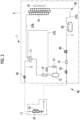
- Fig. 2 shows a refrigerant circuit diagram of the air conditioner 1 according to the present embodiment.
- the air conditioner 1 includes the outdoor unit 3 and the indoor unit 11.
- the refrigerant circuit shown in Fig. 2 is an example and is not limited to a configuration shown in Fig. 2 as long as the circuit is a refrigerant circuit.
- the outdoor unit 3 includes an inverter-driven compressor 13 that compresses the refrigerant, a muffler (silencer) 12 that suppresses vibration noise generated in the compressor 13, a four-way switching valve 17 that switches a circulation direction of the refrigerant, an outdoor heat exchanger 19 that causes the refrigerant to exchange heat with the outside air, a receiver 26 that stores a liquid refrigerant, an expansion valve (EEV) 49, a strainer 14 that removes dust (solid matter) contained in the liquid refrigerant, an accumulator 31 that separates a liquid component from a refrigerant gas sucked into the compressor 13 and causes only the gas to be sucked into the compressor 13, a gas-side operation valve 33, and a liquid-side operation valve 35.
- an inverter-driven compressor 13 that compresses the refrigerant
- a muffler (silencer) 12 that suppresses vibration noise generated in the compressor 13
- a four-way switching valve 17 that switches a circulation
- Each of the above parts on an outdoor unit 3 side is connected as known via refrigerant pipes such as a discharge pipe 37A, a gas pipe 37B, a liquid pipe 37C, and a suction pipe 37E, and constitutes an outdoor-side refrigerant circuit 39.
- refrigerant pipes such as a discharge pipe 37A, a gas pipe 37B, a liquid pipe 37C, and a suction pipe 37E, and constitutes an outdoor-side refrigerant circuit 39.
- the outdoor unit 3 is provided with an outdoor fan 41 that blows the outside air to the outdoor heat exchanger 19.
- a gas-side pipe 5 and a liquid-side pipe 7 are refrigerant pipes provided with the gas-side operation valve 33 and the liquid-side operation valve 35 of the outdoor unit 3 and are connected to the indoor unit 11. Accordingly, one sealed refrigerating cycle 45 is configured.
- the indoor unit 11 includes an indoor heat exchanger 47 that causes the refrigerant to exchange heat with the indoor air to provide indoor air conditioning and an indoor fan 51 that circulates the indoor air through the indoor heat exchanger 47.
- a cooling operation is performed as follows.
- the high-temperature and high-pressure refrigerant gas compressed by the compressor 13 is discharged to the discharge pipe 37A to be supplied to the four-way switching valve 17 via the muffler 12.
- the refrigerant gas is circulated to a gas pipe 37B side by the four-way switching valve 17 and exchanges heat with the outside air blown by the outdoor fan 41 in the outdoor heat exchanger 19 to be liquefied.
- the liquid refrigerant is temporarily stored in the receiver 26 via the liquid pipe 37C.
- the liquid refrigerant whose circulation amount has been adjusted by the receiver 26 is adiabatically expanded by the expansion valve 49 via the liquid-side pipe 7.
- the liquid refrigerant is led out from the outdoor unit 3 via the strainer 14 and the liquid-side operation valve 35 to be supplied to the indoor unit 11.
- the liquid refrigerant flows into the indoor heat exchanger 47 in the indoor unit 11.
- the indoor heat exchanger 47 With the heat exchange between the indoor air circulated by the indoor fan 51 and the refrigerant, the indoor air is cooled and used for indoor cooling.
- the refrigerant is gasified, reaches the four-way switching valve 17 via the gas-side pipe 5 and the gas-side operation valve 33, and is introduced into the accumulator 31 via the suction pipe 37E.
- the liquid component contained in the refrigerant gas is separated, and only the gas component is sucked into the compressor 13.
- This refrigerant is compressed again in the compressor 13, and the cooling operation is performed by repeating the above cycle.
- the high-temperature and high-pressure refrigerant gas compressed by the compressor 13 is discharged to the discharge pipe 37A, supplied to the four-way switching valve 17 via the muffler 12, and then circulated to a gas-side pipe 5 side by the four-way switching valve 17.
- This refrigerant is led out from the outdoor unit 3 via the gas-side operation valve 33 to be introduced into the indoor unit 11.
- the indoor air is heated and used for indoor heating.
- the liquid refrigerant condensed in the indoor heat exchanger 47 is returned to the outdoor unit 3.
- the refrigerant that has returned to the outdoor unit 3 flows into the receiver 26 via the liquid-side operation valve 35, the strainer 14, and the expansion valve 49 and is temporarily stored to adjust the circulation amount.
- the liquid refrigerant flows into the outdoor heat exchanger 19 via the liquid pipe 37C.
- the refrigerant absorbs heat from the outside air and is converted into evaporative gas.
- This refrigerant is introduced from the outdoor heat exchanger 19 to the accumulator 31 via the gas pipe 37B, the four-way switching valve 17, and the suction pipe 37E.
- the liquid component contained in the refrigerant gas is separated, and only the gas component is sucked into the compressor 13 and is compressed again in the compressor 13.
- the heating operation is performed by repeating the above cycle.
- the control device 20 controls the air conditioner 1.
- the control device 20 evaluates comfort in the room to be air-conditioned. Based on the comfort evaluation result, comfort improvement control is performed.
- the control device 20 is configured with, for example, a central processing unit (CPU) (not shown), a memory such as a random access memory (RAM), a computer-readable recording medium, and the like.
- CPU central processing unit
- RAM random access memory
- a series of processing processes for realizing various functions which will be described below is recorded on a recording medium or the like in a form of a program, and this program is read out by the CPU on the RAM or the like to execute processing and operation processes of the information, thereby realizing various functions which will be described below.
- the program may adopt a form in which the program is installed in advance in the ROM or another storage medium, a form in which the program is provided in a stored state in a computer-readable storage medium, or a form in which the program is delivered via wired or wireless communication means.
- the computer-readable storage medium is a magnetic disk, a magneto-optical disk, a CD-ROM, a DVD-ROM, a semiconductor memory, or the like.
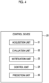
- Fig. 4 is a functional block diagram showing functions of the control device 20 in the air conditioner 1.
- the control device 20 includes an acquisition unit 21, an evaluation unit 22, a notification unit 23, a control unit 24, and a prediction unit 25.
- the acquisition unit 21 acquires temperature information, humidity information, and carbon dioxide concentration information in the room to be air-conditioned. Specifically, the acquisition unit 21 acquires the detection result of the temperature, the humidity, and the carbon dioxide concentration as indoor environment information from the temperature sensor, the humidity sensor, and the CO 2 sensor 15 provided in the indoor unit 11. Information may be acquired as the temperature information, the humidity information, and the carbon dioxide concentration information as long as the information is information from which the temperature, humidity, and carbon dioxide concentration can be indirectly estimated, without directly acquiring the temperature information, the humidity information, and the carbon dioxide concentration information. In the following description, since values are directly acquired from respective sensors, it is assumed that the temperature is used as the temperature information, the humidity is used as the humidity information, and the carbon dioxide concentration is used as the carbon dioxide concentration information.
- the acquisition unit 21 acquires the current indoor environment information.
- the acquired information is output to the evaluation unit 22.
- the evaluation unit 22 evaluates the comfort of the user in the room based on the temperature information (temperature), the humidity information (humidity), and the concentration information (carbon dioxide concentration). Specifically, the evaluation unit 22 evaluates the comfort based on a comfort range of temperature and humidity set in advance according to the carbon dioxide concentration. That is, it is possible to more effectively evaluate the comfort in consideration of the temperature, the humidity, and the carbon dioxide concentration.
- the evaluation unit 22 has information (reference information) indicating the comfort range in which the temperature, the humidity, and the carbon dioxide concentration are associated with each other.
- the information may not be stored in the evaluation unit 22 and may be acquired from another information processing device by downloading or the like.
- Fig. 5 shows an example of the reference information (graph) included in the evaluation unit 22. As shown in Fig. 5 , a range in which the comfort of the user is assumed to be ensured is set for the temperature and the humidity (relative humidity) in the reference information. That is, the comfort is ensured in a temperature range from T1 to T2 for the temperature, and the comfort is ensured in a humidity range from H1 to H2 for the humidity.
- a range surrounded by T1 to T2 and H1 to H2 is the comfort range.
- T1 is 17°C
- T2 is 28°C
- H1 is 40%
- H2 is 700.
- the comfort range of the temperature and the humidity may be, for example, set based on an indoor air environment standard in the Building Management Law or may be randomly set as the range of the temperature and the humidity where the comfort is ensured.
- a boundary line (contour line) indicating a boundary of a range of the temperature and the humidity that may cause the user to feel uncomfortable with the carbon dioxide concentration is shown in the reference information.
- Fig. 5 shows a boundary line L1, a boundary line L2, and a boundary line L3 are shown.
- the carbon dioxide concentration corresponding to the boundary line L1 is the highest
- the concentration corresponding to the boundary line L2 is the second highest
- the concentration corresponding to the boundary line L3 is the lowest.
- the carbon dioxide concentration corresponding to the boundary line L1 is 1500 ppm
- the carbon dioxide concentration corresponding to the boundary line L2 is 1000 ppm
- the carbon dioxide concentration corresponding to the boundary line L3 is 400 ppm.
- Each boundary line indicates that the comfort is ensured as long as a corresponding carbon dioxide concentration is in a temperature and humidity region lower than the boundary line (that is, a region on the lower left side of the boundary line in Fig. 5 is the comfort range).
- the user tends to feel that the air quality is good when the temperature and the humidity are appropriately low for the carbon dioxide concentration. Therefore, the higher the carbon dioxide concentration, the more the boundary line is set in a region where the temperature and the humidity are low.
- the indoor environment is evaluated as comfortable when the indoor environment is within a range (comfort range) where the comfort range in the temperature and humidity (range surrounded by T1 to T2 and H1 to H2) overlaps with the comfort range in the carbon dioxide concentration (temperature and humidity region lower than the boundary line corresponding to the carbon dioxide concentration), and the indoor environment is evaluated as uncomfortable when the indoor environment is outside the range (comfort range).
- a region of R1 in Fig. 5 is the comfort range.
- the temperature is t1
- the humidity is h1
- the indoor environment is within the comfort range and is evaluated as comfortable.
- the temperature is t2
- the humidity is h2
- the indoor environment is not within the comfort range and is evaluated as uncomfortable.
- Fig. 5 is an example of the reference information, and the reference information can be appropriately set based on the relationship between the temperature, the humidity, and the carbon dioxide concentration.
- the reference information can be appropriately set based on the relationship between the temperature, the humidity, and the carbon dioxide concentration.
- a shape of the boundary line is an arc
- the arc is maximum for the humidity at T1
- the arc is maximum for the temperature at H1
- each boundary line for the carbon dioxide concentration is a 1/4 arc (that is, the boundary line set for the comfort range of the temperature and the humidity has a 1/4 arc shape).
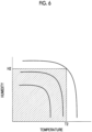
- the reference information has, for example, a shape as shown in Fig. 6 .
- the reference information is not limited to the graph shape of Fig. 5 or Fig. 6 as long as the comfort range is shown in which the temperature, the humidity, and the carbon dioxide concentration are associated with each other.
- the reference information is not limited to the graph as long as the comfort range is shown and may be indicated in another format such as an evaluation formula.
- the evaluation method is not limited to the evaluation of comfort or discomfort for the boundary line.
- a region including the boundary line (for example, region surrounded by parallel lines having a certain distance on both sides of the line with respect to the boundary line) may be set, and the evaluation may be made in stages in which a degree of discomfort is high when the temperature and the humidity are on an outer side in a direction where the temperature and humidity are higher than the region, the degree of discomfort is low when the temperature and the humidity are on an inner side therein, and the evaluation is made as comfortable when the temperature and the humidity are on an outer side in a direction where the temperature and humidity are lower than the region.
- the notification unit 23 notifies the user of the comfort evaluation result. Specifically, the notification unit 23 causes the display unit 16 of the indoor unit 11 to display the comfort evaluation result and performs the notification to the user.
- the notification unit 23 may cause the remote control 2 to perform the display or may cause a mobile terminal (for example, smartphone) of the user to perform the display. In a case where the display on the mobile terminal of the user is performed, a communication network (public notification network) such as Wi-Fi may be used.
- the notification method by the notification unit 23 is not limited to the visual method on the display unit 16, and any method that is recognizable by the user (for example, auditory method) can be employed.
- the comfort evaluation result is displayed on the display unit 16 to indicate the comfort or discomfort.
- the comfort is displayed as “blue”
- the discomfort is displayed as “red”.
- “blue” may be displayed in the case of comfort, "yellow” in the case of low discomfort, and "red” in the case of high discomfort.
- the display method is not limited to the above, and any method that is recognizable by the user can be employed. For example, a method of displaying the evaluation result in stages, a method of displaying the evaluation result in terms of points, or the like can be employed.
- the notification unit 23 notifies the user of outdoor environment information.
- the outdoor environment information includes at least one of outside temperature information, pollen information, or fine particle substance (PM2.5) information.
- PM2.5 fine particle substance
- the user may consider ventilation. However, hot air from the outside air, pollen, or the like may enter the room due to the ventilation and the comfort may be degraded. Therefore, with notification to the user of the outside temperature information or pollen information and the fine particle substance information as the outdoor environment information, it is possible to more efficiently determine whether or not the user performs the ventilation according to the comfort evaluation.
- the method of notifying the outdoor environment information may be displayed on the indoor unit 11 or the remote control 2 or may be displayed on the mobile terminal (for example, smartphone) of the user.
- the control unit 24 controls at least one control target of the air conditioning air volume, the target temperature, or the target humidity in the room, based on the comfort evaluation result. Specifically, in a case where the evaluation unit 22 evaluates that the comfort is poor (uncomfortable), the control unit 24 performs the comfort improvement control to improve the indoor environment.
- the control targets are the air conditioning air volume, the target temperature, and the target humidity will be described.
- the comfort improvement control may be performed with at least one of the control targets as the control target.
- control target is the air conditioning air volume
- the carbon dioxide concentration may be partially (locally) increased in the space.
- the control unit 24 increases the air conditioning air volume to promote the flow of air in the room and agitates the carbon dioxide to suppress the partial increase in the carbon dioxide concentration.
- the air conditioning air volume for example, a rotation speed of the indoor fan 51 is increased to increase an air volume blown into the room.
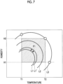
- the boundary line L1 corresponding to the carbon dioxide concentration can be moved to a low concentration side (L1').
- L1' low concentration side
- the ventilation function may be used to reduce the carbon dioxide concentration in the room and thus the comfort may be improved as in Fig. 7 .
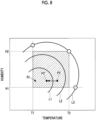
- control target is the target temperature
- the control unit 24 lowers the target temperature to control such that the room temperature is lowered. In the air conditioner 1, the control is performed to follow the set target temperature.
- the control unit 24 lowers the target temperature to change the indoor environment to a point P2'. Since the point P2' is within the comfort range, the comfort of the user is improved.
- the target temperature may be lowered by a fixed value set in advance, or the target temperature may be lowered such that the indoor environment is within the comfort range based on the reference information.
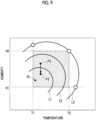
- control target is the target humidity
- the control unit 24 lowers the target humidity to control such that the indoor humidity is lowered.
- the control is performed to follow the set target humidity.
- the control unit 24 lowers the target humidity to change the indoor environment to a point P3'. Since the point P3' is within the comfort range, the comfort of the user is improved.
- the target humidity may be lowered by a fixed value set in advance, or the target humidity may be lowered such that the indoor environment is within the comfort range based on the reference information.
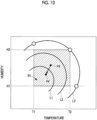
- the control unit 24 lowers the target temperature and the target humidity to change the indoor environment to a point P4'. Since the point P4' is within the comfort range, the comfort of the user is improved.
- the air conditioning air volume, the target temperature, and the target humidity may be controlled at the same time.
- control unit 24 improves the comfort in the room by performing the comfort improvement control with at least one control target of the air conditioning air volume, the target temperature, or the target humidity.
- the prediction unit 25 predicts an increase in the carbon dioxide concentration based on the number of users in the room. As the number of people in the room increases, the carbon dioxide concentration in the room increases significantly, which tends to cause deterioration in the indoor environment (comfort tends to be degraded). For this reason, the prediction unit 25 predicts the increase in the carbon dioxide concentration to suppress the degradation in comfort.
- the prediction unit 25 acquires the number of people in the room based on the information of the human sensor 18.
- a future increase in the carbon dioxide concentration (increasing tendency) is estimated based on the acquired number of people. For example, an amount of increase in the carbon dioxide concentration per hour is estimated according to the number of people to set a future increasing tendency.
- the estimation of the increase in the carbon dioxide concentration may be made in consideration of a volume of the room to be air-conditioned.
- the prediction unit 25 estimates the carbon dioxide concentration after a lapse of a predetermined time and outputs the carbon dioxide concentration to the evaluation unit 22.
- the predetermined time can be randomly set, and is, for example, one hour later.
- the evaluation unit 22 evaluates the comfort after the lapse of the predetermined time based on the temperature information, the humidity information, and the prediction result (carbon dioxide concentration after the lapse of the predetermined time). That is, the evaluation unit 22 evaluates the comfort after the lapse of the predetermined time by using the prediction result of the prediction unit 25 instead of the carbon dioxide concentration information acquired from the CO 2 sensor 15.
- the comfort evaluation method is the same as described above.
- the evaluation unit 22 can evaluate the comfort after the lapse of the predetermined time. With the use of the evaluation result in the notification unit 23 and the control unit 24, the user is notified of the comfort after the lapse of the predetermined time, and the comfort improvement control is performed based on the comfort after the lapse of the predetermined time.
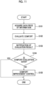
- FIG. 11 A flow shown in Fig. 11 is repeatedly executed at a predetermined control cycle in a case where the air conditioner 1 is started.
- the temperature information, the humidity information, and the carbon dioxide concentration information are acquired (S101).
- the comfort is evaluated based on the acquired temperature information, humidity information, and carbon dioxide concentration information (S102).
- the comfort improvement control is a control of improving comfort by controlling at least one control target of the air conditioning air volume, the target temperature, or the target humidity in the room.
- the air conditioner control device, the air conditioner, the air conditioning method, and the air conditioning program according to the present embodiment it is possible to more effectively evaluate the comfort in consideration of not only the temperature and the humidity but also the carbon dioxide concentration in the room, based on the temperature information, the humidity information, and the carbon dioxide concentration information acquired as the environment information of the room to be air-conditioned.
- the comfort range of the temperature and the humidity is set in advance according to the carbon dioxide concentration, it is possible to evaluate the comfort in consideration of the relationship between the carbon dioxide concentration, the temperature, and the humidity.
- the user can recognize the indoor environment (visualization of air pollution degree). For example, in a case where the user is notified that the comfort is poor, the user can improve the indoor environment by ventilating the room.
- the comfort improvement control Since a state of the comfort in the room can be recognized as the evaluation result, it is possible to perform the comfort improvement control. Specifically, in a case where the air conditioning air volume is controlled, the carbon dioxide stagnant in the room (for example, around the user) can be agitated. Therefore, it is possible to suppress the local increase in the carbon dioxide concentration in the room. Further, in a case where the target temperature or the target humidity is controlled, for example, with the lowering of the target temperature or the target humidity, it is possible to reduce the discomfort of the user.
Landscapes
- Engineering & Computer Science (AREA)
- Signal Processing (AREA)
- Chemical & Material Sciences (AREA)
- Combustion & Propulsion (AREA)
- Mechanical Engineering (AREA)
- General Engineering & Computer Science (AREA)
- Physics & Mathematics (AREA)
- Fuzzy Systems (AREA)
- Mathematical Physics (AREA)
- Air Conditioning Control Device (AREA)
Abstract
Description
- The present disclosure relates to an air conditioner control device, an air conditioner, an air conditioning method, and an air conditioning program.
- In an air conditioner, temperature and humidity are controlled in order to make an indoor environment comfortable. PTL 1 discloses that a ventilation device is controlled according to a carbon dioxide concentration in an indoor environment in order to take air outside a building into a room.
- [PTL 1]
Japanese Patent No. 6415720 - However, in a case where only temperature and humidity are considered in the comfort of the room, the comfort may not be sufficient.
- In PTL 1, since the purpose is ventilation, the ventilation control is performed in consideration of only the carbon dioxide concentration. Thus, it is not possible to comprehensively evaluate the comfort of the room in consideration of the temperature and the humidity.
- The present disclosure has been made in view of such circumstances, and an object of the present disclosure is to provide an air conditioner control device, an air conditioner, an air conditioning method, and an air conditioning program capable of more effectively evaluating comfort.
- A first aspect of the present disclosure is an air conditioner control device including an acquisition unit that acquires temperature information, humidity information, and carbon dioxide concentration information in a room to be air-conditioned, and an evaluation unit that evaluates comfort of a user in the room based on the temperature information, the humidity information, and the concentration information.
- With the configuration as described above, based on the temperature information, the humidity information, and the carbon dioxide concentration information acquired as the environment information of the room to be air-conditioned, it is possible to more effectively evaluate the comfort in consideration of not only the temperature and the humidity but also the carbon dioxide concentration in the room.
- In the air conditioner control device, the evaluation unit may evaluate the comfort based on a comfort range of temperature and humidity set in advance according to a carbon dioxide concentration.
- With the configuration as described above, since the comfort range of the temperature and the humidity is set in advance according to the carbon dioxide concentration, it is possible to evaluate the comfort in consideration of a relationship between the carbon dioxide concentration, the temperature, and the humidity. That is, it is possible to more effectively evaluate the comfort.
- The air conditioner control device may further include a notification unit that notifies the user of an evaluation result of the comfort.
- With the configuration as described above, from the comfort evaluation result in consideration of the carbon dioxide concentration, the user can recognize the indoor environment (visualization of air pollution degree). For example, in a case where the user is notified that the comfort is poor, the user can improve the indoor environment by ventilating the room.
- The air conditioner control device may further include a control unit that controls at least one control target of an air conditioning air volume, a target temperature, or a target humidity in the room based on an evaluation result of the comfort.
- With the configuration as described above, since a state of the comfort in the room can be recognized as the evaluation result, it is possible to perform control of improving the comfort. In a case where the air conditioning air volume is controlled, since the carbon dioxide stagnant in the room (for example, around the user) can be agitated, it is possible to suppress a local increase in the carbon dioxide concentration in the room. In a case where the target temperature or the target humidity is controlled, for example, with lowering of the target temperature and the target humidity, it is possible to reduce the discomfort of the user.
- The air conditioner control device may further include a prediction unit that predicts an increase in a carbon dioxide concentration based on the number of users in the room, and the evaluation unit may use a result of the prediction instead of the concentration information to evaluate the comfort after a lapse of a predetermined time based on the temperature information, the humidity information, and the prediction result.
- With the configuration as described above, it is possible to evaluate the comfort of the room after the lapse of the predetermined time with the prediction of the increase in the carbon dioxide concentration based on the number of users in the room. Therefore, it is possible to know in advance whether or not there is a risk that the carbon dioxide concentration increases after the lapse of the predetermined time, and the comfort is impaired.
- In the air conditioner control device, the notification unit may notify the user of outdoor environment information.
- With the configuration as described above, the user is notified of the outdoor environment information, and thus the user can more efficiently determine whether or not to ventilate the room.
- In the air conditioner control device, the outdoor environment information may include at least one of outside temperature information, pollen information, or fine particle substance information.
- With the configuration as described above, the outdoor environment information includes at least one of the outside temperature information, the pollen information, or the fine particle substance information, and thus the user can more efficiently determine whether or not to ventilate the room.
- A second aspect of the present disclosure is an air conditioner including a refrigerant circuit and the air conditioner control device.
- A third aspect of the present disclosure is an air conditioning method including an acquisition step of acquiring temperature information, humidity information, and carbon dioxide concentration information in a room to be air-conditioned, and an evaluation step of evaluating comfort of a user in the room based on the temperature information, the humidity information, and the concentration information.
- A fourth aspect of the present disclosure is an air conditioning program that causes a computer to execute an acquisition process of acquiring temperature information, humidity information, and carbon dioxide concentration information in a room to be air-conditioned, and an evaluation process of evaluating comfort of a user in the room based on the temperature information, the humidity information, and the concentration information.
- According to the present disclosure, the effect of more effectively evaluating the comfort is achieved.
-
-
Fig. 1 is a diagram showing a schematic configuration of an air conditioner according to an embodiment of the present disclosure. -
Fig. 2 is a diagram showing a refrigerant circuit of the air conditioner according to an embodiment of the present disclosure. -
Fig. 3 is a diagram showing an appearance of an indoor unit of the air conditioner according to an embodiment of the present disclosure. -
Fig. 4 is a functional block diagram showing functions included in a control device in the air conditioner according to an embodiment of the present disclosure. -
Fig. 5 is a graph showing an example of reference information included in the control device according to an embodiment of the present disclosure. -
Fig. 6 is a graph showing an example of the reference information included in the control device according to an embodiment of the present disclosure. -
Fig. 7 is a graph showing an example of comfort improvement control in the control device according to an embodiment of the present disclosure. -
Fig. 8 is a graph showing an example of the comfort improvement control in the control device according to an embodiment of the present disclosure. -
Fig. 9 is a graph showing an example of the comfort improvement control in the control device according to an embodiment of the present disclosure. -
Fig. 10 is a graph showing an example of the comfort improvement control in the control device according to an embodiment of the present disclosure. -
Fig. 11 is a diagram showing a flowchart of processes in the control device according to an embodiment of the present disclosure. - Hereinafter, an embodiment of an air conditioner control device, an air conditioner, an air conditioning method, and an air conditioning program according to the present disclosure will be described with reference to drawings.
-
Fig. 1 is a diagram showing a schematic configuration of an air conditioner 1 according to an embodiment of the present disclosure. As shown inFig. 1 , the air conditioner 1 according to the present embodiment includes anoutdoor unit 3 and anindoor unit 11 as a main configuration. In the present embodiment, as shown inFig. 1 , a case where oneindoor unit 11 is connected to oneoutdoor unit 3 will be described. However, the number ofindoor units 11 is not limited to the above configuration. - The
outdoor unit 3 is disposed, for example, outside in a facility, and performs heat exchange between a refrigerant circulating in a refrigerant circuit described below and outside air. The refrigerant for which the heat exchange is performed in theoutdoor unit 3 is supplied to theindoor unit 11 through the refrigerant circuit. - The
indoor unit 11 is disposed, for example, in a room (air conditioning target) of a facility, and performs the heat exchange between the refrigerant circulating in the refrigerant circuit described below and indoor air. The refrigerant for which the heat exchange is performed in theindoor unit 11 is supplied to theoutdoor unit 3 through the refrigerant circuit. The number ofindoor units 11 connected to oneoutdoor unit 3 can be changed as appropriate. - As shown in
Fig. 1 , a user of theindoor unit 11 can transmit an operation command to theindoor unit 11 by using aremote control 2. Theremote control 2 is disposed corresponding to theindoor unit 11. That is, the user can control the air conditioner 1 by transmitting the command to theindoor unit 11 by using theremote control 2. For example, the user (person in room) can start/stop, set an air conditioning air volume, a target temperature, a target humidity, and the like by using theremote control 2. The command may be transmitted to theindoor unit 11 by an operation button or the like provided on theindoor unit 11. -
Fig. 3 is a diagram showing an appearance of theindoor unit 11. Theindoor unit 11 is provided with a measurement unit (hereinafter referred to as "CO2 sensor") 15 that measures a carbon dioxide concentration, ahuman sensor 18, and adisplay unit 16. The CO2 sensor 15 is measurement equipment that measures the carbon dioxide concentration in the room to be air-conditioned, and thehuman sensor 18 is a detector that detects the presence or absence of a person (the number of people) in the room to be air-conditioned. A detection result in the CO2 sensor 15 or thehuman sensor 18 is used in acontrol device 20 described below. Theindoor unit 11 is also provided with a temperature sensor and a humidity sensor that detect an indoor temperature and humidity. Thedisplay unit 16 is controlled by thecontrol device 20 described below to display various types of information. - Next, the refrigerant circuit in the air conditioner 1 will be described with reference to drawings.
-
Fig. 2 shows a refrigerant circuit diagram of the air conditioner 1 according to the present embodiment. The air conditioner 1 includes theoutdoor unit 3 and theindoor unit 11. The refrigerant circuit shown inFig. 2 is an example and is not limited to a configuration shown inFig. 2 as long as the circuit is a refrigerant circuit. - The
outdoor unit 3 includes an inverter-drivencompressor 13 that compresses the refrigerant, a muffler (silencer) 12 that suppresses vibration noise generated in thecompressor 13, a four-way switching valve 17 that switches a circulation direction of the refrigerant, anoutdoor heat exchanger 19 that causes the refrigerant to exchange heat with the outside air, areceiver 26 that stores a liquid refrigerant, an expansion valve (EEV) 49, astrainer 14 that removes dust (solid matter) contained in the liquid refrigerant, anaccumulator 31 that separates a liquid component from a refrigerant gas sucked into thecompressor 13 and causes only the gas to be sucked into thecompressor 13, a gas-side operation valve 33, and a liquid-side operation valve 35. - Each of the above parts on an
outdoor unit 3 side is connected as known via refrigerant pipes such as adischarge pipe 37A, agas pipe 37B, aliquid pipe 37C, and asuction pipe 37E, and constitutes an outdoor-side refrigerant circuit 39. - The
outdoor unit 3 is provided with anoutdoor fan 41 that blows the outside air to theoutdoor heat exchanger 19. - A gas-side pipe 5 and a liquid-side pipe 7 are refrigerant pipes provided with the gas-
side operation valve 33 and the liquid-side operation valve 35 of theoutdoor unit 3 and are connected to theindoor unit 11. Accordingly, one sealed refrigeratingcycle 45 is configured. - The
indoor unit 11 includes anindoor heat exchanger 47 that causes the refrigerant to exchange heat with the indoor air to provide indoor air conditioning and anindoor fan 51 that circulates the indoor air through theindoor heat exchanger 47. - In the air conditioner 1, a cooling operation is performed as follows.
- The high-temperature and high-pressure refrigerant gas compressed by the
compressor 13 is discharged to thedischarge pipe 37A to be supplied to the four-way switching valve 17 via themuffler 12. - Thereafter, the refrigerant gas is circulated to a
gas pipe 37B side by the four-way switching valve 17 and exchanges heat with the outside air blown by theoutdoor fan 41 in theoutdoor heat exchanger 19 to be liquefied. - The liquid refrigerant is temporarily stored in the
receiver 26 via theliquid pipe 37C. - The liquid refrigerant whose circulation amount has been adjusted by the
receiver 26 is adiabatically expanded by theexpansion valve 49 via the liquid-side pipe 7. - The liquid refrigerant is led out from the
outdoor unit 3 via thestrainer 14 and the liquid-side operation valve 35 to be supplied to theindoor unit 11. - The liquid refrigerant flows into the
indoor heat exchanger 47 in theindoor unit 11. In theindoor heat exchanger 47, with the heat exchange between the indoor air circulated by theindoor fan 51 and the refrigerant, the indoor air is cooled and used for indoor cooling. On the other hand, the refrigerant is gasified, reaches the four-way switching valve 17 via the gas-side pipe 5 and the gas-side operation valve 33, and is introduced into theaccumulator 31 via thesuction pipe 37E. - In the
accumulator 31, the liquid component contained in the refrigerant gas is separated, and only the gas component is sucked into thecompressor 13. - This refrigerant is compressed again in the
compressor 13, and the cooling operation is performed by repeating the above cycle. - On the other hand, a heating operation is performed as follows.
- The high-temperature and high-pressure refrigerant gas compressed by the
compressor 13 is discharged to thedischarge pipe 37A, supplied to the four-way switching valve 17 via themuffler 12, and then circulated to a gas-side pipe 5 side by the four-way switching valve 17. - This refrigerant is led out from the
outdoor unit 3 via the gas-side operation valve 33 to be introduced into theindoor unit 11. - With the heat exchange between the high-temperature and high-pressure refrigerant gas introduced into the
indoor unit 11 and the indoor air circulated via theindoor fan 51 in theindoor heat exchanger 47, the indoor air is heated and used for indoor heating. - The liquid refrigerant condensed in the
indoor heat exchanger 47 is returned to theoutdoor unit 3. - The refrigerant that has returned to the
outdoor unit 3 flows into thereceiver 26 via the liquid-side operation valve 35, thestrainer 14, and theexpansion valve 49 and is temporarily stored to adjust the circulation amount. - The liquid refrigerant flows into the
outdoor heat exchanger 19 via theliquid pipe 37C. - In the
outdoor heat exchanger 19, with the heat exchange between the outside air blown from theoutdoor fan 41 and the refrigerant, the refrigerant absorbs heat from the outside air and is converted into evaporative gas. - This refrigerant is introduced from the
outdoor heat exchanger 19 to theaccumulator 31 via thegas pipe 37B, the four-way switching valve 17, and thesuction pipe 37E. In theaccumulator 31, the liquid component contained in the refrigerant gas is separated, and only the gas component is sucked into thecompressor 13 and is compressed again in thecompressor 13. The heating operation is performed by repeating the above cycle. - Next, the control according to the air conditioner 1 will be described with reference to drawings.
- The
control device 20 controls the air conditioner 1. Thecontrol device 20 evaluates comfort in the room to be air-conditioned. Based on the comfort evaluation result, comfort improvement control is performed. - The
control device 20 is configured with, for example, a central processing unit (CPU) (not shown), a memory such as a random access memory (RAM), a computer-readable recording medium, and the like. A series of processing processes for realizing various functions which will be described below is recorded on a recording medium or the like in a form of a program, and this program is read out by the CPU on the RAM or the like to execute processing and operation processes of the information, thereby realizing various functions which will be described below. The program may adopt a form in which the program is installed in advance in the ROM or another storage medium, a form in which the program is provided in a stored state in a computer-readable storage medium, or a form in which the program is delivered via wired or wireless communication means. The computer-readable storage medium is a magnetic disk, a magneto-optical disk, a CD-ROM, a DVD-ROM, a semiconductor memory, or the like. -
Fig. 4 is a functional block diagram showing functions of thecontrol device 20 in the air conditioner 1. As shown inFig. 4 , thecontrol device 20 includes anacquisition unit 21, anevaluation unit 22, anotification unit 23, acontrol unit 24, and aprediction unit 25. - The
acquisition unit 21 acquires temperature information, humidity information, and carbon dioxide concentration information in the room to be air-conditioned. Specifically, theacquisition unit 21 acquires the detection result of the temperature, the humidity, and the carbon dioxide concentration as indoor environment information from the temperature sensor, the humidity sensor, and the CO2 sensor 15 provided in theindoor unit 11. Information may be acquired as the temperature information, the humidity information, and the carbon dioxide concentration information as long as the information is information from which the temperature, humidity, and carbon dioxide concentration can be indirectly estimated, without directly acquiring the temperature information, the humidity information, and the carbon dioxide concentration information. In the following description, since values are directly acquired from respective sensors, it is assumed that the temperature is used as the temperature information, the humidity is used as the humidity information, and the carbon dioxide concentration is used as the carbon dioxide concentration information. - As described above, the
acquisition unit 21 acquires the current indoor environment information. The acquired information is output to theevaluation unit 22. - The
evaluation unit 22 evaluates the comfort of the user in the room based on the temperature information (temperature), the humidity information (humidity), and the concentration information (carbon dioxide concentration). Specifically, theevaluation unit 22 evaluates the comfort based on a comfort range of temperature and humidity set in advance according to the carbon dioxide concentration. That is, it is possible to more effectively evaluate the comfort in consideration of the temperature, the humidity, and the carbon dioxide concentration. - The
evaluation unit 22 has information (reference information) indicating the comfort range in which the temperature, the humidity, and the carbon dioxide concentration are associated with each other. The information may not be stored in theevaluation unit 22 and may be acquired from another information processing device by downloading or the like.Fig. 5 shows an example of the reference information (graph) included in theevaluation unit 22. As shown inFig. 5 , a range in which the comfort of the user is assumed to be ensured is set for the temperature and the humidity (relative humidity) in the reference information. That is, the comfort is ensured in a temperature range from T1 to T2 for the temperature, and the comfort is ensured in a humidity range from H1 to H2 for the humidity. That is, as for the temperature and the humidity, a range surrounded by T1 to T2 and H1 to H2 is the comfort range. As an example, T1 is 17°C, T2 is 28°C, H1 is 40%, and H2 is 700. The comfort range of the temperature and the humidity may be, for example, set based on an indoor air environment standard in the Building Management Law or may be randomly set as the range of the temperature and the humidity where the comfort is ensured. - A boundary line (contour line) indicating a boundary of a range of the temperature and the humidity that may cause the user to feel uncomfortable with the carbon dioxide concentration is shown in the reference information.
Fig. 5 shows a boundary line L1, a boundary line L2, and a boundary line L3 are shown. The carbon dioxide concentration corresponding to the boundary line L1 is the highest, the concentration corresponding to the boundary line L2 is the second highest, and the concentration corresponding to the boundary line L3 is the lowest. As an example, the carbon dioxide concentration corresponding to the boundary line L1 is 1500 ppm, the carbon dioxide concentration corresponding to the boundary line L2 is 1000 ppm, and the carbon dioxide concentration corresponding to the boundary line L3 is 400 ppm. - Each boundary line indicates that the comfort is ensured as long as a corresponding carbon dioxide concentration is in a temperature and humidity region lower than the boundary line (that is, a region on the lower left side of the boundary line in
Fig. 5 is the comfort range). The user tends to feel that the air quality is good when the temperature and the humidity are appropriately low for the carbon dioxide concentration. Therefore, the higher the carbon dioxide concentration, the more the boundary line is set in a region where the temperature and the humidity are low. - That is, in consideration of the temperature, the humidity, and the carbon dioxide concentration, the indoor environment is evaluated as comfortable when the indoor environment is within a range (comfort range) where the comfort range in the temperature and humidity (range surrounded by T1 to T2 and H1 to H2) overlaps with the comfort range in the carbon dioxide concentration (temperature and humidity region lower than the boundary line corresponding to the carbon dioxide concentration), and the indoor environment is evaluated as uncomfortable when the indoor environment is outside the range (comfort range).
- Specifically, in the current indoor environment, in a case where the carbon dioxide concentration corresponds to the boundary line L1, a region of R1 in
Fig. 5 is the comfort range. For example, in a case where the carbon dioxide concentration corresponds to the boundary line L1, the temperature is t1, and the humidity is h1, the indoor environment is within the comfort range and is evaluated as comfortable. On the other hand, in a case where the carbon dioxide concentration corresponds to the boundary line L1, the temperature is t2, and the humidity is h2, the indoor environment is not within the comfort range and is evaluated as uncomfortable. - As described above, with the setting of the comfort range based on the relationship between the temperature, the humidity, and the carbon dioxide concentration, it is possible to more efficiently evaluate the comfort in consideration of the three factors of the temperature, the humidity, and the carbon dioxide concentration.
-
Fig. 5 is an example of the reference information, and the reference information can be appropriately set based on the relationship between the temperature, the humidity, and the carbon dioxide concentration. For example, in a case where a shape of the boundary line is an arc, the arc is maximum for the humidity at T1, and the arc is maximum for the temperature at H1, each boundary line for the carbon dioxide concentration is a 1/4 arc (that is, the boundary line set for the comfort range of the temperature and the humidity has a 1/4 arc shape). - In a case where the comfort range of the temperature and the humidity is defined only by a maximum value, the reference information has, for example, a shape as shown in
Fig. 6 . - As described above, the reference information is not limited to the graph shape of
Fig. 5 orFig. 6 as long as the comfort range is shown in which the temperature, the humidity, and the carbon dioxide concentration are associated with each other. The reference information is not limited to the graph as long as the comfort range is shown and may be indicated in another format such as an evaluation formula. - The evaluation method is not limited to the evaluation of comfort or discomfort for the boundary line. A region including the boundary line (for example, region surrounded by parallel lines having a certain distance on both sides of the line with respect to the boundary line) may be set, and the evaluation may be made in stages in which a degree of discomfort is high when the temperature and the humidity are on an outer side in a direction where the temperature and humidity are higher than the region, the degree of discomfort is low when the temperature and the humidity are on an inner side therein, and the evaluation is made as comfortable when the temperature and the humidity are on an outer side in a direction where the temperature and humidity are lower than the region.
- The
notification unit 23 notifies the user of the comfort evaluation result. Specifically, thenotification unit 23 causes thedisplay unit 16 of theindoor unit 11 to display the comfort evaluation result and performs the notification to the user. Thenotification unit 23 may cause theremote control 2 to perform the display or may cause a mobile terminal (for example, smartphone) of the user to perform the display. In a case where the display on the mobile terminal of the user is performed, a communication network (public notification network) such as Wi-Fi may be used. The notification method by thenotification unit 23 is not limited to the visual method on thedisplay unit 16, and any method that is recognizable by the user (for example, auditory method) can be employed. - The comfort evaluation result is displayed on the
display unit 16 to indicate the comfort or discomfort. For example, the comfort is displayed as "blue", the discomfort is displayed as "red". In a case where the evaluation is made in stages, on thedisplay unit 16, "blue" may be displayed in the case of comfort, "yellow" in the case of low discomfort, and "red" in the case of high discomfort. The display method is not limited to the above, and any method that is recognizable by the user can be employed. For example, a method of displaying the evaluation result in stages, a method of displaying the evaluation result in terms of points, or the like can be employed. - The
notification unit 23 notifies the user of outdoor environment information. The outdoor environment information includes at least one of outside temperature information, pollen information, or fine particle substance (PM2.5) information. Depending on the display of the comfort evaluation, the user may consider ventilation. However, hot air from the outside air, pollen, or the like may enter the room due to the ventilation and the comfort may be degraded. Therefore, with notification to the user of the outside temperature information or pollen information and the fine particle substance information as the outdoor environment information, it is possible to more efficiently determine whether or not the user performs the ventilation according to the comfort evaluation. The method of notifying the outdoor environment information may be displayed on theindoor unit 11 or theremote control 2 or may be displayed on the mobile terminal (for example, smartphone) of the user. - The
control unit 24 controls at least one control target of the air conditioning air volume, the target temperature, or the target humidity in the room, based on the comfort evaluation result. Specifically, in a case where theevaluation unit 22 evaluates that the comfort is poor (uncomfortable), thecontrol unit 24 performs the comfort improvement control to improve the indoor environment. In the present embodiment, a case where the control targets are the air conditioning air volume, the target temperature, and the target humidity will be described. However, the comfort improvement control may be performed with at least one of the control targets as the control target. - First, a case where the control target is the air conditioning air volume will be described.
- In the room to be air-conditioned, the carbon dioxide concentration may be partially (locally) increased in the space. In particular, in a case where the carbon dioxide concentration is high in a region around the user, the user tends to feel uncomfortable. For this reason, in a case where the comfort evaluation result is determined to be uncomfortable, the
control unit 24 increases the air conditioning air volume to promote the flow of air in the room and agitates the carbon dioxide to suppress the partial increase in the carbon dioxide concentration. Regarding the air conditioning air volume, for example, a rotation speed of theindoor fan 51 is increased to increase an air volume blown into the room. - As described above, with the increase in the air conditioning air volume, for example, as shown in
Fig. 7 , the boundary line L1 corresponding to the carbon dioxide concentration can be moved to a low concentration side (L1'). Thus, it is possible to improve the comfort even in a case where the indoor environment (temperature and humidity) is at a point P1. - In a case where the air conditioner 1 has a ventilation function (function of discharging inside air to the outside and taking the outside air into the room), the ventilation function may be used to reduce the carbon dioxide concentration in the room and thus the comfort may be improved as in
Fig. 7 . - Next, a case where the control target is the target temperature will be described.
- As shown in
Fig. 5 , with lowering of the temperature for the carbon dioxide concentration, the user tends to feel the comfort. For this reason, in a case where the comfort evaluation result is determined to be uncomfortable, thecontrol unit 24 lowers the target temperature to control such that the room temperature is lowered. In the air conditioner 1, the control is performed to follow the set target temperature. - Specifically, as shown in
Fig. 8 , in a case where the indoor environment (temperature and humidity) is at a point P2 and the carbon dioxide concentration corresponds to the boundary line L1, the user may feel uncomfortable. For this reason, thecontrol unit 24 lowers the target temperature to change the indoor environment to a point P2'. Since the point P2' is within the comfort range, the comfort of the user is improved. - In the case where the target temperature is changed, the target temperature may be lowered by a fixed value set in advance, or the target temperature may be lowered such that the indoor environment is within the comfort range based on the reference information.
- Next, a case where the control target is the target humidity will be described.
- As shown in
Fig. 5 , with lowering of the humidity for the carbon dioxide concentration, the user tends to feel the comfort. For this reason, in a case where the comfort evaluation result is determined to be uncomfortable, thecontrol unit 24 lowers the target humidity to control such that the indoor humidity is lowered. In the air conditioner 1, the control is performed to follow the set target humidity. - Specifically, as shown in
Fig. 9 , in a case where the indoor environment (temperature and humidity) is at a point P3 and the carbon dioxide concentration corresponds to the boundary line L1, the user may feel uncomfortable. For this reason, thecontrol unit 24 lowers the target humidity to change the indoor environment to a point P3'. Since the point P3' is within the comfort range, the comfort of the user is improved. - In a case where the target humidity is changed, the target humidity may be lowered by a fixed value set in advance, or the target humidity may be lowered such that the indoor environment is within the comfort range based on the reference information.
- It is also effective to control both the target temperature and the target humidity. Specifically, as shown in
Fig. 10 , in a case where the indoor environment (temperature and humidity) is at a point P4 and the carbon dioxide concentration corresponds to the boundary line L1, the user may feel uncomfortable. For this reason, thecontrol unit 24 lowers the target temperature and the target humidity to change the indoor environment to a point P4'. Since the point P4' is within the comfort range, the comfort of the user is improved. - The air conditioning air volume, the target temperature, and the target humidity may be controlled at the same time.
- As described above, the
control unit 24 improves the comfort in the room by performing the comfort improvement control with at least one control target of the air conditioning air volume, the target temperature, or the target humidity. - The
prediction unit 25 predicts an increase in the carbon dioxide concentration based on the number of users in the room. As the number of people in the room increases, the carbon dioxide concentration in the room increases significantly, which tends to cause deterioration in the indoor environment (comfort tends to be degraded). For this reason, theprediction unit 25 predicts the increase in the carbon dioxide concentration to suppress the degradation in comfort. - Specifically, the
prediction unit 25 acquires the number of people in the room based on the information of thehuman sensor 18. A future increase in the carbon dioxide concentration (increasing tendency) is estimated based on the acquired number of people. For example, an amount of increase in the carbon dioxide concentration per hour is estimated according to the number of people to set a future increasing tendency. - The estimation of the increase in the carbon dioxide concentration may be made in consideration of a volume of the room to be air-conditioned.
- The
prediction unit 25 estimates the carbon dioxide concentration after a lapse of a predetermined time and outputs the carbon dioxide concentration to theevaluation unit 22. The predetermined time can be randomly set, and is, for example, one hour later. Theevaluation unit 22 evaluates the comfort after the lapse of the predetermined time based on the temperature information, the humidity information, and the prediction result (carbon dioxide concentration after the lapse of the predetermined time). That is, theevaluation unit 22 evaluates the comfort after the lapse of the predetermined time by using the prediction result of theprediction unit 25 instead of the carbon dioxide concentration information acquired from the CO2 sensor 15. The comfort evaluation method is the same as described above. - With the estimation of the carbon dioxide concentration after the lapse of the predetermined time in the
prediction unit 25, theevaluation unit 22 can evaluate the comfort after the lapse of the predetermined time. With the use of the evaluation result in thenotification unit 23 and thecontrol unit 24, the user is notified of the comfort after the lapse of the predetermined time, and the comfort improvement control is performed based on the comfort after the lapse of the predetermined time. - Therefore, it is possible to evaluate in advance whether or not there is a risk that the carbon dioxide concentration increases after the lapse of the predetermined time and the comfort is impaired and to take measures.
- Next, processes in the
control device 20 will be described with reference toFig. 11 . A flow shown inFig. 11 is repeatedly executed at a predetermined control cycle in a case where the air conditioner 1 is started. - First, the temperature information, the humidity information, and the carbon dioxide concentration information are acquired (S101).
- Next, the comfort is evaluated based on the acquired temperature information, humidity information, and carbon dioxide concentration information (S102).
- Next, the user is notified of the evaluation result (S103).
- Next, determination is made whether or not the comfort evaluation is good (S104). That is, determination is made whether or not the comfort evaluation result is comfortable.
- In a case where the comfort evaluation is good (YES determination in S104), the process ends.
- When the comfort evaluation is not good (NO determination in S104), the comfort improvement control is performed (S105). The comfort improvement control is a control of improving comfort by controlling at least one control target of the air conditioning air volume, the target temperature, or the target humidity in the room.
- The order of the process of S103 and the processes of S104 and S105 may be changed, or one of the processes may be performed.
- As described above, with the air conditioner control device, the air conditioner, the air conditioning method, and the air conditioning program according to the present embodiment, it is possible to more effectively evaluate the comfort in consideration of not only the temperature and the humidity but also the carbon dioxide concentration in the room, based on the temperature information, the humidity information, and the carbon dioxide concentration information acquired as the environment information of the room to be air-conditioned.
- Since the comfort range of the temperature and the humidity is set in advance according to the carbon dioxide concentration, it is possible to evaluate the comfort in consideration of the relationship between the carbon dioxide concentration, the temperature, and the humidity.
- With the comfort evaluation result in consideration of the carbon dioxide concentration, the user can recognize the indoor environment (visualization of air pollution degree). For example, in a case where the user is notified that the comfort is poor, the user can improve the indoor environment by ventilating the room.
- Since a state of the comfort in the room can be recognized as the evaluation result, it is possible to perform the comfort improvement control. Specifically, in a case where the air conditioning air volume is controlled, the carbon dioxide stagnant in the room (for example, around the user) can be agitated. Therefore, it is possible to suppress the local increase in the carbon dioxide concentration in the room. Further, in a case where the target temperature or the target humidity is controlled, for example, with the lowering of the target temperature or the target humidity, it is possible to reduce the discomfort of the user.
- With the prediction of the increase in the carbon dioxide concentration based on the number of users in the room, it is possible to evaluate the comfort of the room after the lapse of the predetermined time. Therefore, it is possible to know in advance whether or not there is a risk that the carbon dioxide concentration increases after the lapse of the predetermined time, and the comfort is impaired.
- The present disclosure is not limited to only the embodiments described above, and various modifications can be made within a scope which does not depart from the gist of the invention.
-
- 1: Air conditioner
- 2: Remote control
- 3: Outdoor unit
- 5: Gas-side pipe
- 7: Liquid-side pipe
- 11: Indoor unit
- 12: Muffler
- 13: Compressor
- 14: Strainer
- 15: CO2 sensor
- 16: Display unit
- 17: Four-way switching valve
- 18: Human sensor
- 19: Outdoor heat exchanger
- 20: Control device
- 21: Acquisition unit
- 22: Evaluation unit
- 23: Notification unit
- 24: Control unit
- 25: Prediction unit
- 26: Receiver
- 31: Accumulator
- 33: Gas-side operation valve
- 35: Liquid-side operation valve
- 37A: Discharge pipe
- 37B: Gas pipe
- 37C: Liquid pipe
- 37E: Suction pipe
- 39: Outdoor-side refrigerant circuit
- 41: Outdoor fan
- 45: Refrigerating cycle
- 47: Indoor heat exchanger
- 49: Expansion valve
- 51: Indoor fan
Claims (10)
- An air conditioner control device comprising:an acquisition unit that acquires temperature information, humidity information, and carbon dioxide concentration information in a room to be air-conditioned; andan evaluation unit that evaluates comfort of a user in the room based on the temperature information, the humidity information, and the concentration information.
- The air conditioner control device according to Claim 1,
wherein the evaluation unit evaluates the comfort based on a comfort range of temperature and humidity set in advance according to a carbon dioxide concentration. - The air conditioner control device according to Claim 1 or 2, further comprising:
a notification unit that notifies the user of an evaluation result of the comfort. - The air conditioner control device according to any one of Claims 1 to 3, further comprising:
a control unit that controls at least one control target of an air conditioning air volume, a target temperature, or a target humidity in the room based on an evaluation result of the comfort. - The air conditioner control device according to any one of Claims 1 to 4, further comprising:a prediction unit that predicts an increase in a carbon dioxide concentration based on the number of users in the room,wherein the evaluation unit uses a result of the prediction instead of the concentration information to evaluate the comfort after a lapse of a predetermined time.
- The air conditioner control device according to Claim 3,
wherein the notification unit notifies the user of outdoor environment information. - The air conditioner control device according to Claim 6,
wherein the outdoor environment information includes at least one of outside temperature information, pollen information, or fine particle substance information. - An air conditioner comprising:a refrigerant circuit; andthe air conditioner control device according to any one of Claims 1 to 7.
- An air conditioning method comprising:an acquisition step of acquiring temperature information, humidity information, and carbon dioxide concentration information in a room to be air-conditioned; andan evaluation step of evaluating comfort of a user in the room based on the temperature information, the humidity information, and the concentration information.
- An air conditioning program that causes a computer to execute:an acquisition process of acquiring temperature information, humidity information, and carbon dioxide concentration information in a room to be air-conditioned; andan evaluation process of evaluating comfort of a user in the room based on the temperature information, the humidity information, and the concentration information.
Applications Claiming Priority (2)
| Application Number | Priority Date | Filing Date | Title |
|---|---|---|---|
| JP2021027325A JP7767015B2 (en) | 2021-02-24 | 2021-02-24 | Air conditioner control device, air conditioner, air conditioning method, and air conditioning program |
| PCT/JP2021/039653 WO2022180931A1 (en) | 2021-02-24 | 2021-10-27 | Air conditioner control device, air conditioner, air conditioning method, and air conditioning program |
Publications (2)
| Publication Number | Publication Date |
|---|---|
| EP4283205A1 true EP4283205A1 (en) | 2023-11-29 |
| EP4283205A4 EP4283205A4 (en) | 2024-06-19 |
Family
ID=83047963
Family Applications (1)
| Application Number | Title | Priority Date | Filing Date |
|---|---|---|---|
| EP21928026.0A Pending EP4283205A4 (en) | 2021-02-24 | 2021-10-27 | Air conditioner control device, air conditioner, air conditioning method, and air conditioning program |
Country Status (4)
| Country | Link |
|---|---|
| EP (1) | EP4283205A4 (en) |
| JP (1) | JP7767015B2 (en) |
| AU (1) | AU2021429884A1 (en) |
| WO (1) | WO2022180931A1 (en) |
Families Citing this family (1)
| Publication number | Priority date | Publication date | Assignee | Title |
|---|---|---|---|---|
| JP2024049712A (en) * | 2022-09-29 | 2024-04-10 | 三菱重工サーマルシステムズ株式会社 | Indoor unit of air conditioning system, air conditioning system, control device, and method and program for controlling indoor unit of air conditioning system |
Family Cites Families (18)
| Publication number | Priority date | Publication date | Assignee | Title |
|---|---|---|---|---|
| JP3852463B2 (en) * | 2004-09-28 | 2006-11-29 | ダイキン工業株式会社 | ENVIRONMENTAL NAVIGATION DEVICE AND ENVIRONMENTAL NAVIGATION PROGRAM |
| JP4836967B2 (en) * | 2008-01-23 | 2011-12-14 | 株式会社東芝 | Air conditioning control support screen generation device, air conditioning control support screen generation method, and air conditioning monitoring system |
| JP5514507B2 (en) * | 2009-10-21 | 2014-06-04 | 株式会社日立製作所 | In-area environment control system and in-area environment control method |
| JP5377577B2 (en) * | 2011-06-06 | 2013-12-25 | 株式会社東芝 | Data processing apparatus and sensor system for measuring carbon dioxide concentration |
| JP5532153B1 (en) * | 2013-01-10 | 2014-06-25 | ダイキン工業株式会社 | Air conditioning system |
| JP6111499B2 (en) * | 2013-02-13 | 2017-04-12 | パナソニックIpマネジメント株式会社 | Air conditioning system, indicating device |
| EP2990734B1 (en) * | 2013-04-22 | 2018-12-26 | Mitsubishi Electric Corporation | Air-conditioning control system and method |
| JP6169534B2 (en) * | 2014-05-29 | 2017-07-26 | シャープ株式会社 | Message notification device, message notification method, message output device, message output system, portable device, automobile, air conditioning device, and program |
| DE112014006809T5 (en) * | 2014-07-16 | 2017-03-30 | Mitsubishi Electric Corporation | Air conditioning control, air conditioning control method and program |
| KR102116160B1 (en) * | 2014-11-28 | 2020-05-27 | 케이웨더(주) | Apparatus for intergration indoor environment management |
| EP3299975B1 (en) * | 2015-05-18 | 2023-08-23 | Mitsubishi Electric Corporation | Indoor environment model creation device |
| JP2017096584A (en) * | 2015-11-26 | 2017-06-01 | パナソニックIpマネジメント株式会社 | Air conditioning system and program |
| TWI598541B (en) * | 2016-01-19 | 2017-09-11 | 台達電子工業股份有限公司 | Power optimization system for air-side apparatus of air conditioning and power optimization method of the same |
| JP7037432B2 (en) * | 2017-07-12 | 2022-03-16 | 三菱電機ビルテクノサービス株式会社 | Comfort display device |
| JP2019068238A (en) * | 2017-09-29 | 2019-04-25 | 株式会社富士通ゼネラル | Air conditioning system, air conditioner, communication method and data acquisition display program |
| JP7460876B2 (en) * | 2019-04-22 | 2024-04-03 | ダイキン工業株式会社 | air conditioning system |
| JP6939841B2 (en) * | 2019-04-22 | 2021-09-22 | ダイキン工業株式会社 | Air conditioning system |
| CN111854829A (en) * | 2019-04-29 | 2020-10-30 | 热映光电股份有限公司 | Environment comfort display method and display device thereof |
-
2021
- 2021-02-24 JP JP2021027325A patent/JP7767015B2/en active Active
- 2021-10-27 EP EP21928026.0A patent/EP4283205A4/en active Pending
- 2021-10-27 AU AU2021429884A patent/AU2021429884A1/en not_active Abandoned
- 2021-10-27 WO PCT/JP2021/039653 patent/WO2022180931A1/en not_active Ceased
Also Published As
| Publication number | Publication date |
|---|---|
| JP7767015B2 (en) | 2025-11-11 |
| WO2022180931A1 (en) | 2022-09-01 |
| EP4283205A4 (en) | 2024-06-19 |
| AU2021429884A1 (en) | 2023-09-07 |
| JP2022128874A (en) | 2022-09-05 |
Similar Documents
| Publication | Publication Date | Title |
|---|---|---|
| JP4720919B2 (en) | Compressor operation control device and air conditioner equipped with the same | |
| US12595923B2 (en) | Leakage detection and mitigation system | |
| CN109392304B (en) | Air conditioning system, air conditioning method and control device | |
| JP7330363B2 (en) | air conditioning system | |
| KR101502096B1 (en) | Control method of air conditioner | |
| US20140069131A1 (en) | Air conditioning system | |
| JP6270996B2 (en) | Air conditioner | |
| CN109237721B (en) | Electronic expansion valve fault detection method for air conditioner | |
| JP5619056B2 (en) | Air conditioner | |
| JP2009216283A (en) | Air-conditioning control system | |
| KR20090044785A (en) | Refrigerant leak detection system and control method | |
| EP3792565B1 (en) | Air conditioning system | |
| CN104006497A (en) | One-to-multi air conditioning system refrigerant flow control method and device | |
| JPWO2017068686A1 (en) | Refrigeration cycle equipment | |
| JP2013185803A (en) | Heat pump hydronic heater | |
| AU2021429884A1 (en) | Air conditioner control device, air conditioner, air conditioning method, and air conditioning program | |
| JP6804272B2 (en) | Air conditioner control device | |
| JP2019120422A (en) | Air-conditioning management system | |
| KR101913511B1 (en) | A controlling method of an air conditioner | |
| CN115823710B (en) | Air conditioning equipment and operating parameter adjustment method thereof | |
| CN119022357B (en) | air conditioner | |
| WO2019198277A1 (en) | Air conditioning system | |
| JP7209040B2 (en) | air conditioner | |
| JP2020153529A (en) | Operation condition determination system for pre-cooling operation or pre-warming operation of air conditioners | |
| KR20260023367A (en) | Air conditioner which performs oil recovery operation and method for controlling the same |
Legal Events
| Date | Code | Title | Description |
|---|---|---|---|
| STAA | Information on the status of an ep patent application or granted ep patent |
Free format text: STATUS: THE INTERNATIONAL PUBLICATION HAS BEEN MADE |
|
| PUAI | Public reference made under article 153(3) epc to a published international application that has entered the european phase |
Free format text: ORIGINAL CODE: 0009012 |
|
| STAA | Information on the status of an ep patent application or granted ep patent |
Free format text: STATUS: REQUEST FOR EXAMINATION WAS MADE |
|
| 17P | Request for examination filed |
Effective date: 20230822 |
|
| AK | Designated contracting states |
Kind code of ref document: A1 Designated state(s): AL AT BE BG CH CY CZ DE DK EE ES FI FR GB GR HR HU IE IS IT LI LT LU LV MC MK MT NL NO PL PT RO RS SE SI SK SM TR |
|
| DAV | Request for validation of the european patent (deleted) | ||
| DAX | Request for extension of the european patent (deleted) | ||
| A4 | Supplementary search report drawn up and despatched |
Effective date: 20240522 |
|
| RIC1 | Information provided on ipc code assigned before grant |
Ipc: F24F 120/00 20180101ALI20240515BHEP Ipc: F24F 130/10 20180101ALI20240515BHEP Ipc: F24F 11/65 20180101ALI20240515BHEP Ipc: F24F 11/64 20180101ALI20240515BHEP Ipc: F24F 11/30 20180101ALI20240515BHEP Ipc: F24F 110/70 20180101ALI20240515BHEP Ipc: F24F 110/65 20180101ALI20240515BHEP Ipc: F24F 110/64 20180101ALI20240515BHEP Ipc: F24F 110/20 20180101ALI20240515BHEP Ipc: F24F 110/12 20180101ALI20240515BHEP Ipc: F24F 110/10 20180101ALI20240515BHEP Ipc: F24F 11/74 20180101ALI20240515BHEP Ipc: F24F 11/63 20180101ALI20240515BHEP Ipc: F24F 11/50 20180101AFI20240515BHEP |