EP4283132A1 - Blower device, and utilization unit and heat source unit of air conditioner device, water heater, and air purifier, having the blower device - Google Patents
Blower device, and utilization unit and heat source unit of air conditioner device, water heater, and air purifier, having the blower device Download PDFInfo
- Publication number
- EP4283132A1 EP4283132A1 EP22745794.2A EP22745794A EP4283132A1 EP 4283132 A1 EP4283132 A1 EP 4283132A1 EP 22745794 A EP22745794 A EP 22745794A EP 4283132 A1 EP4283132 A1 EP 4283132A1
- Authority
- EP
- European Patent Office
- Prior art keywords
- revolutions
- motor
- control unit
- fan
- control
- Prior art date
- Legal status (The legal status is an assumption and is not a legal conclusion. Google has not performed a legal analysis and makes no representation as to the accuracy of the status listed.)
- Pending
Links
- XLYOFNOQVPJJNP-UHFFFAOYSA-N water Substances O XLYOFNOQVPJJNP-UHFFFAOYSA-N 0.000 title claims abstract description 73
- 239000000314 lubricant Substances 0.000 claims abstract description 21
- 230000015572 biosynthetic process Effects 0.000 abstract description 30
- 239000003507 refrigerant Substances 0.000 description 64
- 230000007246 mechanism Effects 0.000 description 24
- 238000004140 cleaning Methods 0.000 description 22
- 238000010438 heat treatment Methods 0.000 description 17
- 238000001816 cooling Methods 0.000 description 16
- 239000007788 liquid Substances 0.000 description 15
- 238000004378 air conditioning Methods 0.000 description 12
- 239000004519 grease Substances 0.000 description 8
- 238000005259 measurement Methods 0.000 description 7
- 238000005057 refrigeration Methods 0.000 description 6
- 230000008878 coupling Effects 0.000 description 5
- 238000010168 coupling process Methods 0.000 description 5
- 238000005859 coupling reaction Methods 0.000 description 5
- 238000010586 diagram Methods 0.000 description 4
- 230000001629 suppression Effects 0.000 description 4
- 230000004048 modification Effects 0.000 description 3
- 238000012986 modification Methods 0.000 description 3
- 230000006835 compression Effects 0.000 description 2
- 238000007906 compression Methods 0.000 description 2
- 230000006837 decompression Effects 0.000 description 2
- 239000000428 dust Substances 0.000 description 2
- 230000035943 smell Effects 0.000 description 2
- WHXSMMKQMYFTQS-UHFFFAOYSA-N Lithium Chemical compound [Li] WHXSMMKQMYFTQS-UHFFFAOYSA-N 0.000 description 1
- XSQUKJJJFZCRTK-UHFFFAOYSA-N Urea Chemical compound NC(N)=O XSQUKJJJFZCRTK-UHFFFAOYSA-N 0.000 description 1
- 239000004202 carbamide Substances 0.000 description 1
- 238000001704 evaporation Methods 0.000 description 1
- 230000008020 evaporation Effects 0.000 description 1
- 230000004907 flux Effects 0.000 description 1
- 230000005764 inhibitory process Effects 0.000 description 1
- 229910052744 lithium Inorganic materials 0.000 description 1
- 238000005461 lubrication Methods 0.000 description 1
- 239000000696 magnetic material Substances 0.000 description 1
- 230000009467 reduction Effects 0.000 description 1
- 238000007789 sealing Methods 0.000 description 1
- 239000000344 soap Substances 0.000 description 1
- 238000009834 vaporization Methods 0.000 description 1
- 230000008016 vaporization Effects 0.000 description 1
Images




Classifications
-
- F—MECHANICAL ENGINEERING; LIGHTING; HEATING; WEAPONS; BLASTING
- F04—POSITIVE - DISPLACEMENT MACHINES FOR LIQUIDS; PUMPS FOR LIQUIDS OR ELASTIC FLUIDS
- F04D—NON-POSITIVE-DISPLACEMENT PUMPS
- F04D27/00—Control, e.g. regulation, of pumps, pumping installations or pumping systems specially adapted for elastic fluids
- F04D27/004—Control, e.g. regulation, of pumps, pumping installations or pumping systems specially adapted for elastic fluids by varying driving speed
-
- F—MECHANICAL ENGINEERING; LIGHTING; HEATING; WEAPONS; BLASTING
- F24—HEATING; RANGES; VENTILATING
- F24F—AIR-CONDITIONING; AIR-HUMIDIFICATION; VENTILATION; USE OF AIR CURRENTS FOR SCREENING
- F24F11/00—Control or safety arrangements
- F24F11/50—Control or safety arrangements characterised by user interfaces or communication
- F24F11/61—Control or safety arrangements characterised by user interfaces or communication using timers
-
- F—MECHANICAL ENGINEERING; LIGHTING; HEATING; WEAPONS; BLASTING
- F04—POSITIVE - DISPLACEMENT MACHINES FOR LIQUIDS; PUMPS FOR LIQUIDS OR ELASTIC FLUIDS
- F04D—NON-POSITIVE-DISPLACEMENT PUMPS
- F04D29/00—Details, component parts, or accessories
- F04D29/06—Lubrication
- F04D29/063—Lubrication specially adapted for elastic fluid pumps
-
- F—MECHANICAL ENGINEERING; LIGHTING; HEATING; WEAPONS; BLASTING
- F24—HEATING; RANGES; VENTILATING
- F24F—AIR-CONDITIONING; AIR-HUMIDIFICATION; VENTILATION; USE OF AIR CURRENTS FOR SCREENING
- F24F1/00—Room units for air-conditioning, e.g. separate or self-contained units or units receiving primary air from a central station
- F24F1/0007—Indoor units, e.g. fan coil units
- F24F1/0018—Indoor units, e.g. fan coil units characterised by fans
- F24F1/0022—Centrifugal or radial fans
-
- F—MECHANICAL ENGINEERING; LIGHTING; HEATING; WEAPONS; BLASTING
- F24—HEATING; RANGES; VENTILATING
- F24F—AIR-CONDITIONING; AIR-HUMIDIFICATION; VENTILATION; USE OF AIR CURRENTS FOR SCREENING
- F24F1/00—Room units for air-conditioning, e.g. separate or self-contained units or units receiving primary air from a central station
- F24F1/06—Separate outdoor units, e.g. outdoor unit to be linked to a separate room comprising a compressor and a heat exchanger
- F24F1/38—Fan details of outdoor units, e.g. bell-mouth shaped inlets or fan mountings
-
- F—MECHANICAL ENGINEERING; LIGHTING; HEATING; WEAPONS; BLASTING
- F04—POSITIVE - DISPLACEMENT MACHINES FOR LIQUIDS; PUMPS FOR LIQUIDS OR ELASTIC FLUIDS
- F04D—NON-POSITIVE-DISPLACEMENT PUMPS
- F04D29/00—Details, component parts, or accessories
- F04D29/05—Shafts or bearings, or assemblies thereof, specially adapted for elastic fluid pumps
- F04D29/056—Bearings
- F04D29/059—Roller bearings
-
- F—MECHANICAL ENGINEERING; LIGHTING; HEATING; WEAPONS; BLASTING
- F16—ENGINEERING ELEMENTS AND UNITS; GENERAL MEASURES FOR PRODUCING AND MAINTAINING EFFECTIVE FUNCTIONING OF MACHINES OR INSTALLATIONS; THERMAL INSULATION IN GENERAL
- F16C—SHAFTS; FLEXIBLE SHAFTS; ELEMENTS OR CRANKSHAFT MECHANISMS; ROTARY BODIES OTHER THAN GEARING ELEMENTS; BEARINGS
- F16C2360/00—Engines or pumps
- F16C2360/46—Fans, e.g. ventilators
-
- F—MECHANICAL ENGINEERING; LIGHTING; HEATING; WEAPONS; BLASTING
- F16—ENGINEERING ELEMENTS AND UNITS; GENERAL MEASURES FOR PRODUCING AND MAINTAINING EFFECTIVE FUNCTIONING OF MACHINES OR INSTALLATIONS; THERMAL INSULATION IN GENERAL
- F16C—SHAFTS; FLEXIBLE SHAFTS; ELEMENTS OR CRANKSHAFT MECHANISMS; ROTARY BODIES OTHER THAN GEARING ELEMENTS; BEARINGS
- F16C33/00—Parts of bearings; Special methods for making bearings or parts thereof
- F16C33/30—Parts of ball or roller bearings
- F16C33/66—Special parts or details in view of lubrication
- F16C33/6603—Special parts or details in view of lubrication with grease as lubricant
-
- F—MECHANICAL ENGINEERING; LIGHTING; HEATING; WEAPONS; BLASTING
- F24—HEATING; RANGES; VENTILATING
- F24F—AIR-CONDITIONING; AIR-HUMIDIFICATION; VENTILATION; USE OF AIR CURRENTS FOR SCREENING
- F24F11/00—Control or safety arrangements
- F24F11/70—Control systems characterised by their outputs; Constructional details thereof
- F24F11/72—Control systems characterised by their outputs; Constructional details thereof for controlling the supply of treated air, e.g. its pressure
- F24F11/74—Control systems characterised by their outputs; Constructional details thereof for controlling the supply of treated air, e.g. its pressure for controlling air flow rate or air velocity
- F24F11/77—Control systems characterised by their outputs; Constructional details thereof for controlling the supply of treated air, e.g. its pressure for controlling air flow rate or air velocity by controlling the speed of ventilators
-
- Y—GENERAL TAGGING OF NEW TECHNOLOGICAL DEVELOPMENTS; GENERAL TAGGING OF CROSS-SECTIONAL TECHNOLOGIES SPANNING OVER SEVERAL SECTIONS OF THE IPC; TECHNICAL SUBJECTS COVERED BY FORMER USPC CROSS-REFERENCE ART COLLECTIONS [XRACs] AND DIGESTS
- Y02—TECHNOLOGIES OR APPLICATIONS FOR MITIGATION OR ADAPTATION AGAINST CLIMATE CHANGE
- Y02B—CLIMATE CHANGE MITIGATION TECHNOLOGIES RELATED TO BUILDINGS, e.g. HOUSING, HOUSE APPLIANCES OR RELATED END-USER APPLICATIONS
- Y02B30/00—Energy efficient heating, ventilation or air conditioning [HVAC]
- Y02B30/70—Efficient control or regulation technologies, e.g. for control of refrigerant flow, motor or heating
Definitions
- the present disclosure relates to a fan device, and a utilization unit and a heat source unit of an air conditioner, a hot water supplier, and an air cleaner each including the fan device.
- Patent Literature 1 Japanese Laid-Open Patent Publication No. 2017-067046 discloses a fan device (fan) including a shaft (motor shaft), a bearing supporting the motor shaft, a tubular sleeve disposed between the bearing and an end of the motor shaft and penetrated by the motor shaft, a tubular fan boss disposed between the sleeve and an end of the motor shaft and penetrated by the motor shaft, and a fastening member disposed at an end of the motor shaft, in which the sleeve and the fan boss are interposed between the bearing and the fastening member.
- Examples of the bearing applied to a motor as disclosed in Patent Literature 1 include a bearing that can enclose lubricant such as grease to secure long-time lubrication.
- lubricant such as grease
- the present disclosure proposes a fan device that can suppress electric power consumption of a motor as well as can prevent poor oil film formation in a bearing enclosing lubricant, and also proposes a utilization unit and a heat source unit of an air conditioner, a hot water supplier, and an air cleaner each including the fan device.
- a fan device includes a motor and a control unit.
- the motor has a shaft supported by a bearing enclosing lubricant, and has a variable number of revolutions.
- the control unit drives the motor.
- the control unit executes at least one of first control and second control. During the first control, if the control unit continuously drives the motor at a first number of revolutions or less for a first time period, the control unit drives the motor at a second number of revolutions more than the first number of revolutions and then drives the motor at the first number of revolutions or less.
- the control unit drives the motor at a fourth number of revolutions and then drives the motor at a third number of revolutions or less, the third number of revolutions being less than the fourth number of revolutions.
- the motor is driven at the second number of revolutions for oil film formation. This achieves both suppression of electric power consumption by driving the motor at the first number of revolutions as well as oil film formation in the bearing by driving the motor at the second number of revolutions.
- the fan device can accordingly suppress electric power consumption of the motor as well as inhibit poor oil film formation in the bearing enclosing the lubricant.
- a fan device is the fan device according to the first aspect, in which the first number of revolutions or the third number of revolutions is 50 rpm or more and less than 300 rpm.
- a fan device is the fan device according to the first or second aspect, in which the second number of revolutions or the fourth number of revolutions is 300 rpm or more.
- a fan device is the fan device according to any one of the first to third aspects, in which the first time period is 10 minutes or more and 5 hours or less.
- a fan device is the fan device according to any one of the first to fourth aspects, in which the control unit drives the motor at the second number of revolutions for a time period of one second or more and two minutes or less.
- a utilization unit includes the fan device according to any one of the first to fifth aspects.
- a fan device is the utilization unit according to the sixth aspect, in which the case where the drive state of the motor shifts from the stopped state into the rotating state includes a case where an air conditioner returns from thermo-off operation.
- the utilization unit of the air conditioner can inhibit poor oil film formation in the bearing of the motor during thermo-off operation.
- a heat source unit of an air conditioner according to an eighth aspect includes the fan device according to any one of the first to fifth aspects.
- the heat source unit of the air conditioner can suppress electric power consumption of the motor as well as inhibit poor oil film formation in the bearing enclosing the lubricant.
- a hot water supplier according to a ninth aspect includes the fan device according to any one of the first to fifth aspects.
- the hot water supplier can suppress electric power consumption of the motor as well as inhibit poor oil film formation in the bearing enclosing the lubricant.
- An air cleaner according to a tenth aspect includes the fan device according to any one of the first to fifth aspects.
- the air cleaner can suppress electric power consumption of the motor as well as inhibit poor oil film formation in the bearing enclosing the lubricant.
- a fan device according to the present disclosure is exemplarily applied to a utilization unit of an air conditioner configured to achieve a vapor compression refrigeration cycle, though not limited in terms of its use. Described below with reference to the drawings is an air conditioner 1 including a fan device 100 exemplifying the fan device according to the present disclosure.
- FIG. 1 is a schematic configuration diagram of the air conditioner 1 including a fan device according to an embodiment of the present disclosure.
- the air conditioner 1 is configured to achieve the vapor compression refrigeration cycle to cool and heat an air conditioning target space.
- the air conditioning target space include a space in a building such as an office building, a commercial facility, or a residence.
- the air conditioner 1 principally includes a heat source unit 12, a utilization unit 13, a liquid-refrigerant connection pipe 14, a gas-refrigerant connection pipe 15, and a control unit 123 configured to control devices constituting the heat source unit 12 and the utilization unit 13.
- the liquid-refrigerant connection pipe 14 and the gas-refrigerant connection pipe 15 are refrigerant connection pipes connecting the heat source unit 12 and the utilization unit 13.
- the heat source unit 12 and the utilization unit 13 are connected via the refrigerant connection pipes 14 and 15 to constitute a refrigerant circuit 16.
- the air conditioner 1 depicted in FIG. 1 includes the single utilization unit 13.
- the air conditioner 1 may alternatively include a plurality of utilization units 13 connected parallelly to the heat source unit 12 by the refrigerant connection pipes 14 and 15.
- the air conditioner 1 may still alternatively include a plurality of heat source units 12.
- the air conditioner 1 may be of an integral type including the heat source unit 12 and the utilization unit 13 that are formed integrally with each other.
- the heat source unit 12 principally includes an accumulator 17, a compressor 18, a flow direction switching mechanism 110, a heat source heat exchanger 111, an expansion mechanism 112, a liquid-side shutoff valve 113, a gas-side shutoff valve 114, and a heat source fan 115.
- the utilization unit 13 principally includes a utilization heat exchanger 132 and a utilization fan 133.
- the fan device 100 includes the control unit 123 and the utilization fan 133.
- the air conditioner 1 will be described in terms of its behavior.
- the control unit 123 controls behavior of the flow direction switching mechanism 110 to switch the refrigerant circuit 16 into a state where the heat source heat exchanger 111 functions as a refrigerant radiator (condenser) and the utilization heat exchanger 132 functions as a refrigerant evaporator. Specifically, the control unit 123 controls behavior of the flow direction switching mechanism 110 to cause a suction tube 117 connected to a suction side of the compressor 18 to communicate with a second gas refrigerant tube 121 connecting the flow direction switching mechanism 110 and the gas-side shutoff valve 114.
- control unit 123 controls behavior of the flow direction switching mechanism 110 to cause a discharge tube 118 connected to a discharge side of the compressor 18 to communicate with a first gas refrigerant tube 119 connecting the flow direction switching mechanism 110 and a gas side of the heat source heat exchanger 111 (see solid lines in the flow direction switching mechanism 110 in FIG. 1 ).
- control unit 123 operates the compressor 18, the heat source fan 115, and the utilization fan 133.
- control unit 123 adjusts, in accordance with measurement values and the like of various sensors, the compressor 18, the number of revolutions of each of a fan motor 115a of the heat source fan 115 and a fan motor 134 of the utilization fan 133, and an opening degree of an electronic expansion valve exemplifying the expansion mechanism 112 to a predetermined opening degree.
- a low-pressure gas refrigerant in the refrigeration cycle is sucked into the compressor 18, is compressed to have high pressure in the refrigeration cycle, and is then discharged from the compressor 18.
- a high-pressure gas refrigerant discharged from the compressor 18 is sent to the heat source heat exchanger 111 via the flow direction switching mechanism 110.
- the high-pressure gas refrigerant sent to the heat source heat exchanger 111 exchanges heat with air serving as a cooling source supplied by the heat source fan 115 in the heat source heat exchanger 111 functioning as a refrigerant radiator to radiate heat, and comes into a high-pressure liquid refrigerant.
- the high-pressure liquid refrigerant obtained by radiating heat in the heat source heat exchanger 111 is sent to the expansion mechanism 112 via a liquid refrigerant tube 120.
- the high-pressure liquid refrigerant is decompressed to come into a low-pressure refrigerant in a gas-liquid two-phase state.
- the low-pressure refrigerant in the gas-liquid two-phase state obtained by decompression in the expansion mechanism 112 is sent to the utilization heat exchanger 132 via the liquid refrigerant tube 120, the liquid-side shutoff valve 113 and the liquid-refrigerant connection pipe 14.
- the low-pressure refrigerant in the gas-liquid two-phase state sent to the utilization heat exchanger 132 exchanges heat to be evaporated, with air supplied into the air conditioning target space by the utilization fan 133 in the utilization heat exchanger 132 functioning as a refrigerant evaporator.
- air cooled through heat exchange with the refrigerant is supplied into the air conditioning target space to cool the air conditioning target space.
- the low-pressure gas refrigerant evaporated in the utilization heat exchanger 132 is sucked into the compressor 18 again via the gas-refrigerant connection pipe 15, the gas-side shutoff valve 114, the flow direction switching mechanism 110, and the accumulator 17.
- the control unit 123 controls behavior of the flow direction switching mechanism 110 to switch the refrigerant circuit 16 into a state where the heat source heat exchanger 111 functions as a refrigerant evaporator and the utilization heat exchanger 132 functions as a refrigerant radiator (condenser). Specifically, the control unit 123 controls behavior of the flow direction switching mechanism 110 to cause the suction tube 117 to communicate with the first gas refrigerant tube 119 and cause the discharge tube 118 to communicate with the second gas refrigerant tube 121 (see broken lines in the flow direction switching mechanism 110 in FIG. 1 ). During heating operation, the control unit 123 operates the compressor 18, the heat source fan 115, and the utilization fan 133.
- control unit 123 adjusts, in accordance with measurement values and the like of various sensors, the compressor 18, the number of revolutions of each of the fan motor 115a of the heat source fan 115 and the fan motor 134 of the utilization fan 133, and an opening degree of an electronic expansion valve exemplifying the expansion mechanism 112 to a predetermined opening degree.
- the control unit 123 controls behavior of various devices in the air conditioner 1 in this manner, the low-pressure gas refrigerant in the refrigeration cycle is sucked into the compressor 18, is compressed to have high pressure in the refrigeration cycle, and is then discharged from the compressor 18.
- the high-pressure gas refrigerant discharged from the compressor 18 is sent to the utilization heat exchanger 132 via the flow direction switching mechanism 110, the gas-side shutoff valve 114, and the gas-refrigerant connection pipe 15.
- the high-pressure gas refrigerant sent to the utilization heat exchanger 132 exchanges heat with air supplied into the air conditioning target space by the utilization fan 133 in the utilization heat exchanger 132 functioning as a refrigerant radiator (condenser) to radiate heat and come into a high-pressure liquid refrigerant.
- air heated through heat exchange with the refrigerant is supplied into the air conditioning target space to heat the air conditioning target space.
- the high-pressure liquid refrigerant obtained by radiating heat in the utilization heat exchanger 132 is sent to the expansion mechanism 112 via the liquid-refrigerant connection pipe 14, the liquid-side shutoff valve 113, and the liquid refrigerant tube 120.
- the refrigerant sent to the expansion mechanism 112 is decompressed by the expansion mechanism 112 to come into a low-pressure refrigerant in the gas-liquid two-phase state.
- the low-pressure refrigerant in the gas-liquid two-phase state obtained by decompression in the expansion mechanism 112 is sent to the heat source heat exchanger 111 via the liquid refrigerant tube 120.
- the low-pressure refrigerant in the gas-liquid two-phase state sent to the heat source heat exchanger 111 exchanges heat with air serving as a heating source supplied by the heat source fan 115 in the heat source heat exchanger 111 functioning as a refrigerant evaporator to be evaporated and come into a low-pressure gas refrigerant.
- the low-pressure refrigerant obtained by evaporation in the heat source heat exchanger 111 is sucked into the compressor 18 again via the flow direction switching mechanism 110 and the accumulator 17.
- the fan device 100 includes the control unit 123 and the utilization fan 133.
- the utilization fan 133 principally includes the fan motor 134 and a fan rotor 135.
- FIG. 2 is a sectional view of the fan motor 134.
- the fan motor 134 rotation-drives the fan rotor 135.
- the fan motor 134 is of an outer rotor type.
- the fan motor 134 is an inverter motor including an inverter (not depicted) and having a variable number of revolutions. The number of revolutions of the fan motor 134 is controlled in accordance with a control signal outputted from the control unit 123.
- the fan motor 134 principally includes a stator 134a, a rotor 134b, a shaft 134c, two bearings 134d, and a casing 134e.
- the fan motor 134 exemplifies a motor.
- the stator 134a is a substantially tubular member, and principally includes a stator core 134a1 made of a magnetic material and having a cylindrical shape, and a stator coil 134a2 wound around the stator core 134a1.
- the stator core 134a1 is disposed to have a center axis substantially matching a center axis of the stator 134a.
- the center axis of the stator 134a and the center axis of the stator core 134a1 match a shaft of the fan rotor 135.
- Each of the center axes will be hereinafter called a shaft center O.
- the stator 134a has an outer circumference provided with a bolt hole 134a4 used to fix the casing 134e to the stator 134a with bolts.
- the stator 134a is fixed to a casing (not depicted) of the utilization unit 13.
- the stator 134a includes a connector 134a3 used to supply the stator coil 134a2 with electric power.
- the inverter included in the fan motor 134 is connected to the control unit 123 via a data line connected to the connector 134a3.
- the fan motor 134 receives a control signal from the control unit 123 via the connector 134a3 and the data line.
- the rotor 134b is a cup-shaped member disposed to have a predetermined gap from the outer circumference of the stator 134a.
- the rotor 134b principally includes a flat part 134b1, an outer sleeve 134b2, and a coupling portion 134b3.
- the flat part 134b1 is principally formed into a substantially circular disc shape.
- the flat part 134b1 has a center provided with a circular opening 134b5 used to dispose the coupling portion 134b3.
- the opening 134b5 is positioned to have a center perpendicular to the shaft center O.
- the outer sleeve 134b2 is formed into a substantially tubular shape extending from an outer circumferential portion of the flat part 134b1 toward the stator 134a along the shaft center O.
- the outer sleeve 134b2 includes a magnetic pole member 134b4 supplying the stator 134a with field magnetic flux.
- the magnetic pole member 134b4 faces an outer circumferential surface of the stator coil 134a2 via an air gap.
- the coupling portion 134b3 is a cylindrical member attached to the opening 134b5 of the flat part 134b 1.
- the coupling portion 134b3 has an outer circumferential surface fixed to an inner circumferential surface of the opening 134b5 of the flat part 134b1.
- the coupling portion 134b3 has an inner circumference to which the shaft 134c having a columnar shape is fixed to have a center axis matching the shaft center O.
- FIG. 3 is an enlarged view of the bearing 134d and the periphery thereof surrounded with a frame A.
- the bearing 134d is a ball bearing including an outer ring 134d1, an inner ring 134d2, and a ball 134d3.
- the outer ring 134d1 has an outer circumferential surface fitted to be fixed to an inner circumferential surface of the stator 134a
- the inner ring 134d2 has an inner circumferential surface fitted to be fixed to an outer circumferential surface of the shaft 134c.
- the bearing 134d is of a hermetically sealed type filled therein with lubricant 134d5 such as grease.
- a sealing member 134d4 to hermetically seal a space accommodating the ball 134d3 at each end, in an extending direction of the shaft center O, of each of the outer ring 134d1 and the inner ring 134d2.
- the space is filled with the lubricant 134d5 such as grease.
- the lubricant 134d5 include urea grease and lithium soap grease, though not limited thereto.
- the two bearings 134d support the shaft 134c in the fan motor 134.
- the two bearings 134d are aligned on an inner circumference of the stator 134a to have a predetermined gap in the extending direction of the shaft center O.
- the casing 134e is a cup-shaped member accommodating the stator 134a as well as the rotor 134b.
- the casing 134e includes a flat part 134e1 and an outer sleeve 134e2.
- the flat part 134e1 is principally formed into a substantially circular disc shape facing the flat part 134b1 of the rotor 134b.
- the flat part 134e1 has a center provided with an opening 134e3 allowing the shaft 134c to penetrate.
- the flat part 134e1 faces the flat part 134b1 of the rotor 134b with a predetermined gap therebetween.
- the outer sleeve 134e2 is formed into a substantially tubular shape extending from an outer circumferential portion of the flat part 134e1 toward the stator 134a along the shaft center O.
- the outer sleeve 134e2 faces the outer sleeve 134b2 of the rotor 134b with a predetermined gap therebetween.
- the casing 134e has a bolt hole 134e4 provided at an end, adjacent to the stator 134a, of the outer sleeve 134b2.
- the casing 134e is fixed to the stator when a bolt is fastened to the bolt hole 134a4 of the stator 134a via the bolt hole 134e4.
- the fan rotor 135 is fixed to an end, far from the stator 134a, of the shaft 134c.
- control unit 123 Upon control of the heat source unit 12 and the utilization unit 13 during cooling operation and heating operation described above, the control unit 123 executes at least one of first control and second control for inhibition of poor oil film formation in the bearings 134d of the fan motor.
- the first control and the second control will be described in detail later.
- the control unit 123 is embodied by a computer.
- the control unit 123 includes a control arithmetic device and a storage device.
- Examples of the control arithmetic device can include a processor such as a CPU or a GPU.
- the control arithmetic device reads a program stored in the storage device and executes predetermined image processing or arithmetic processing in accordance with the program.
- the control arithmetic device is further configured to write an arithmetic result to the storage device, and read information stored in the storage device, in accordance with the program.
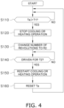
- FIG. 4 is a flowchart depicting a control flow of the first control. The control flow depicted in FIG. 4 starts when the air conditioner 1 is powered on.
- step S110 the control unit 123 detects a number of revolutions of the fan motor 134 during cooling operation or heating operation, calculates an accumulated time period Ta of time periods at a number of revolutions equal to or less than the predetermined first number of revolutions R1, and determines whether or not the accumulated time period Ta exceeds the predetermined first time period T1.
- the control unit 123 advances to step S120 if the accumulated time period Ta exceeds the predetermined first time period T1 (Yes), or repeats processing in step S110 until the accumulated time period Ta exceeds the predetermined first time period T1 (No).
- the control unit 123 controls the number of revolutions of the fan motor 134 in accordance with measurement values and the like of various sensors as in normal cooling operation and heating operation until the accumulated time period Ta exceeds the predetermined first time period T1.
- the first number of revolutions R1 suppresses electric power consumption of the fan motor 134 while highly possibly causing poor oil film formation in the bearings 134d of the fan motor 134 if the fan motor 134 is continuously driven for more than the first time period T1.
- the first number of revolutions R1 is exemplarily 50 rpm or more and less than 300 rpm.
- the first time period T1 is 10 minutes or more and 5 hours or less.
- step S120 the control unit 123 temporarily stops normal cooling operation or heating operation (cooling or heating operation), and advances to step S130.
- step S130 the control unit 123 changes the number of revolutions of the fan motor 134 to the predetermined second number of revolutions R2 more than the first number of revolutions R1, and advances to step S140.
- step S140 the control unit 123 determines whether or not the fan motor 134 is driven at the second number of revolutions R2 for the predetermined second time period T2.
- the control unit 123 advances to step S150 if the control unit 123 determines that the fan motor 134 is driven at the second number of revolutions R2 for the second time period T2 (Yes).
- the control unit 123 repeats processing in step S140 if the control unit 123 determines that the fan motor 134 is not driven at the second number of revolutions R2 for the second time period T2 (No).
- the second number of revolutions R2 enables oil film formation in the bearings 134d of the fan motor 134 during the second time period T2, and is more than the first number of revolutions R1.
- the second time period T2 does not cause influence on air conditioning capacity of the air conditioner 1 when the fan motor 134 rotates at the second number of revolutions R2.
- the second number of revolutions R2 is exemplarily 300 rpm or more.
- the second time period T2 is exemplarily one second or more and two minutes or less.
- step S150 the control unit 123 restarts cooling operation or heating operation stopped in step S120, starts controlling the number of revolutions of the fan motor 134 in accordance with measurement values and the like of various sensors, and advances to step S160.
- the control unit 123 drives the fan motor 134 at the first number of revolutions R1 or less.
- step S160 the control unit 123 resets the accumulated time period Ta to zero, and advances to step S110.
- FIG. 5 is a flowchart depicting a control flow of the second control. The control flow depicted in FIG. 5 starts when the air conditioner 1 is powered on.
- step S210 the control unit 123 determines whether or not the fan motor 134 shifts from the stopped state into the rotating state.
- the control unit 123 advances to step S220 if the control unit 123 determines that the fan motor 134 shifts from the stopped state into the rotating state (Yes).
- the control unit 123 repeats processing in step S210 if the control unit 123 determines that the fan motor 134 does not shift from the stopped state into the rotating state (No).
- thermo-off operation is a control in which the control unit 123 tops air conditioning operation of the air conditioner 1 when temperature in the air conditioning target space is out of a predetermined allowable temperature range including set temperature of the air conditioner 1.
- the control unit 123 brings the compressor 18 and the fan motor 134 into the stopped state.
- the control unit 123 shifts the fan motor 134 from the stopped state into the rotating state.
- step S220 the control unit 123 temporarily stops normal cooling operation or heating operation, and advances to step S230.
- step S230 the control unit 123 changes the number of revolutions of the fan motor 134 to the predetermined fourth number of revolutions R4 more than the predetermined third number of revolutions R3, and advances to step S240.
- step S240 the control unit 123 determines whether or not the fan motor 134 is driven at the fourth number of revolutions R4 for the predetermined second time period T2.
- the control unit 123 advances to step S250 if the control unit 123 determines that the fan motor 134 is driven at the fourth number of revolutions R4 for the second time period T2 (Yes).
- the control unit 123 repeats processing in step S240 if the control unit 123 determines that the fan motor 134 is not driven at the fourth number of revolutions R4 for the second time period T2 (No).
- the third number of revolutions R3 suppresses electric power consumption of the fan motor 134 while highly possibly causing poor oil film formation in the bearings 134d of the fan motor 134 if the fan motor 134 is continuously driven for more than the first time period T1.
- the third number of revolutions R3 is exemplarily 50 rpm or more and less than 300 rpm.
- the third number of revolutions R3 may be equal to or may be different from the first number of revolutions R1.
- the fourth number of revolutions R4 enables oil film formation in the bearings 134d of the fan motor 134 during the second time period T2, and is more than the third number of revolutions R3.
- the fourth number of revolutions is exemplarily 300 rpm or more.
- step S250 the control unit 123 restarts cooling operation or heating operation stopped in step S220, starts controlling the number of revolutions of the fan motor 134 in accordance with measurement values and the like of various sensors, and advances to step S210.
- the control unit 123 drives the fan motor 134 at the third number of revolutions R3 or less.
- the fan device 100 includes the fan motor 134 and the control unit 123.
- the fan motor 134 includes the shaft 134c supported by the bearings 134d enclosing the lubricant 134d5, and has a variable number of revolutions.
- the control unit 123 drives the fan motor 134.
- the control unit 123 executes at least one of the first control and the second control. During the first control, if the control unit 123 continuously drives the fan motor 134 at the first number of revolutions R1 or less for the first time period T1, the control unit 123 drives the fan motor 134 at the second number of revolutions R2 more than the first number of revolutions R1 and then drives the fan motor 134 at the first number of revolutions R1 or less.
- the control unit 123 drives the fan motor 134 at the fourth number of revolutions R4 and then drives the fan motor 134 at the third number of revolutions R3 or less, the third number of revolutions R3 being less than the fourth number of revolutions R4.
- the fan motor 134 is desirably driven at a small number of revolutions or stopped.
- the shaft 134c is rotated at a small number of revolutions for a long period of time or is stopped continuously in the fan motor 134 including the bearings 134d lubricated by the lubricant 134d5
- the bearings 134d may have poor oil film formation, in which case preferred oil film formation is not achieved in the bearings 134d.
- control unit 123 executes at least one of the first control and the second control, to suppress electric power consumption of the fan motor 134 as well as to inhibit poor oil film formation.
- the fan motor 134 is driven at the second number of revolutions R2 for oil film formation. This achieves both suppression of electric power consumption by driving the fan motor 134 at the first number of revolutions R1 and oil film formation in the bearings 134d by driving the fan motor 134 at the second number of revolutions R2.
- the fan motor 134 Due to the second control executed by the control unit 123, if the fan motor 134 shifts from the stopped state into the rotating state, the fan motor 134 is driven at the fourth number of revolutions R4 for oil film formation. This achieves both suppression of electric power consumption by stopping the fan motor 134 and oil film formation in the bearings 134d by driving the fan motor 134 at the fourth number of revolutions R4.
- the fan device 100 can accordingly suppress electric power consumption of the fan motor 134 as well as inhibit poor oil film formation in the bearings 134d enclosing the lubricant 134d5.
- the utilization unit 13 in the air conditioner 1 includes the fan device 100.
- the utilization unit 13 can thus suppress electric power consumption of the fan motor 134 as well as inhibit poor oil film formation in the bearings 134d enclosing the lubricant 134d5.
- Examples of the case where the drive state of the fan motor 134 shifts from the stopped state into the rotating state include the case where the air conditioner 1 returns from thermo-off operation.
- the utilization unit 13 in the air conditioner 1 can thus inhibit poor oil film formation in the bearings 134d of the fan motor 134 during thermo-off operation.
- the above description exemplifies the case where the fan device according to the present disclosure is applied to the utilization unit 13 in the air conditioner 1.
- the fan device according to the present disclosure may alternatively be applied to the heat source unit 12 in the air conditioner 1.
- the fan device according to the present disclosure may be include the control unit 123 and the heat source fan 115 included in the heat source unit 12 in the air conditioner 1.
- the heat source fan 115 principally includes the fan motor 115a and a fan rotor 115b. Similarly to the fan motor 134, the fan motor 115a includes a bearing supporting a shaft. Similarly to the bearings 134d, the bearing of the fan motor 115a is of a hermetically sealed type filled therein with lubricant such as grease.
- the control unit 123 executes at least one of the first control and the second control also for the fan motor 115a of the heat source fan 115.
- the heat source unit 12 in the air conditioner 1 can accordingly suppress electric power consumption of the fan motor 115a as well as inhibit poor oil film formation in the fan motor 115a.
- the fan device according to the present disclosure may be applied to a hot water supplier. Described below with reference to the drawings is a hot water supplier 2 including a fan device 215 exemplifying the fan device according to the present disclosure.
- FIG. 6 is a schematic configuration diagram of the hot water supplier 2.
- the hot water supplier 2 includes a heat pump unit 22 and a water unit 23.
- the heat pump unit 22 includes a compressor 211, an outdoor heat exchanger 212, an expansion valve 213, a hot water supply heat exchanger 216, the fan device 215, a refrigerant pipe 240, and a control unit 220.
- the control unit 220 is provided for both the heat pump unit 22 and the water unit 23.
- the compressor 211, the outdoor heat exchanger 212, the expansion valve 213, the fan device 215, and the hot water supply heat exchanger 216 constitute a refrigerant circuit 241 allowing circulation of a refrigerant in the refrigerant pipe 240.
- the compressor 211 has a discharge side connected with a refrigerant inflow port of the hot water supply heat exchanger 216.
- the compressor 211 has a suction side connected with a first end of the outdoor heat exchanger 212.
- the outdoor heat exchanger 212 has a second end connected with a first end of the expansion valve 213.
- the expansion valve 213 has a second end connected with a refrigerant outflow port of the hot water supply heat exchanger 216.
- the fan device 215 is disposed to face the outdoor heat exchanger 212. When the fan device 215 rotates, the outdoor heat exchanger 212 is supplied with air to promote heat exchange between the air and the refrigerant in the outdoor heat exchanger 212.
- the fan device 215 includes the control unit 220 and a fan 215a.
- the fan 215a principally includes a fan motor 215a1 and a fan rotor 215a2.
- the fan motor 215a1 includes a bearing (not depicted) supporting a shaft.
- the bearing of the fan motor 215a1 is of a hermetically sealed type filled therein with lubricant such as grease.
- the water unit 23 includes a pump 217, a hot water supply tank 25, a gas hot water supplier 26, a hot water supply terminal 210, water pipes 245 and 246, and an outputted hot water temperature sensor 222.
- the pump 217 and the hot water supply heat exchanger 216 constitute a warm water circuit 248 allowing circulation of warm water in the water pipe 245.
- the pump 217 has a discharge side connected with a warm water inflow port of the hot water supply heat exchanger 216.
- the pump 217 has a suction side connected with a first end of the hot water supply tank 25.
- the hot water supply heat exchanger 216 has a warm water outflow port connected to a second end of the hot water supply tank 25.
- the control unit 220 of the hot water supplier 2 executes heat application operation.
- heat application operation forms a heat application cycle (positive cycle) in which the refrigerant discharged from the compressor 211 flows to the hot water supply heat exchanger 216, the expansion valve 213, and the outdoor heat exchanger 212 in the mentioned order, and the refrigerant having passed the outdoor heat exchanger 212 returns to the compressor 211.
- the hot water supply heat exchanger 216 functions as a condenser
- the outdoor heat exchanger 212 functions as an evaporator.
- Heat application operation involves heating hot water supply warm water through heat exchange between the hot water supply warm water and the refrigerant flowing into the hot water supply heat exchanger 216 from the discharge side of the compressor 211.
- the warm water circuit 248 has circulation of warm water subject to heat exchange with the refrigerant flowing in the hot water supply heat exchanger 216. Specifically, during heat application operation, the hot water supply heat exchanger 216 is supplied with hot water supply warm water discharged from the hot water supply tank 25 by the pump 217, and warm water heated in the hot water supply heat exchanger 216 is returned into the hot water supply tank 25.
- the gas hot water supplier 26 connected to the hot water supply tank 25 via the water pipe 246 includes a heater 26a and is connected to the hot water supply terminal 210.
- the gas hot water supplier 26 can thus heat the hot water supply warm water supplied from the hot water supply tank 25 and not yet supplied to the hot water supply terminal 210.
- the hot water supply terminal 210 allows a user to use warm water in the hot water supply tank 25.
- control unit 220 adjusts, in accordance with measurement values and the like of various sensors including the outputted hot water temperature sensor 222, the compressor 211, the number of revolutions of the fan motor 215a1 of the fan 215a, and an opening degree of the expansion valve 213 to a predetermined opening degree.
- the control unit 220 is connected to various sensors and control targets (the compressor 211, the fan motor 215a1, and the expansion valve 213) via signal lines, though the signal lines are not depicted in FIG. 6 for convenience.
- control unit 220 of the hot water supplier 2 executes at least one of the first control and the second control. Contents of such control are basically similar to contents of the control executed by the control unit 123, and will thus not be detailed again.
- the control unit 220 executes heat application operation as described above. In the control flow of each of the first control and the second control depicted in FIG. 4 and FIG. 5 , "cooling or heating operation” will thus be replaced with “heat application operation".
- the hot water supplier 2 includes the fan device 215.
- the hot water supplier 2 can thus suppress electric power consumption of the fan motor 215a1 as well as inhibit poor oil film formation in the bearing of the fan motor 215a1.
- the fan device according to the present disclosure may be applied to an air cleaner. Described below with reference to the drawings is an air cleaner 3 including a fan device 328 exemplifying the fan device according to the present disclosure.
- FIG. 7 is a perspective view from diagonally ahead, of the air cleaner 3.
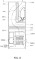
- FIG. 8 is a sectional view of the air cleaner 3.
- FIG. 7 depicts such that four vertical side surfaces are removed to visualize an internal structure.
- the air cleaner 3 includes a casing 331, the fan device 328, an air cleaning filter 322, and a humidifying element 324.
- the casing 331 has an interior divided into a blast chamber 331a, an air cleaning chamber 331b, and a humidifying chamber 331c.
- the blast chamber 331a, the air cleaning chamber 331b, and the humidifying chamber 331c are aligned in the mentioned order from bottom to top.
- the blast chamber 331a accommodates the fan device 328.
- the air cleaning chamber 331b accommodates the air cleaning filter 322.
- the humidifying chamber 331c accommodates the humidifying element 324.
- the blast chamber 331a and the air cleaning chamber 331b interpose a first opening 311.
- the first opening 311 allows air to flow from the blast chamber 331a to the air cleaning chamber 331b.
- the air cleaning chamber 331b and the humidifying chamber 331c interpose a second opening 312.
- the second opening 312 allows air to flow from the air cleaning chamber 331b to the humidifying chamber 331c.
- the fan device 328 includes a control unit 328a and a fan 328b.
- the fan 328b principally includes a fan rotor 328b1, a fan motor 328b2, and a scroll 328b3.
- the fan rotor 328b1 is a sirocco fan rotation-driven by the fan motor 328b2.
- the fan motor 328b2 includes a bearing (not depicted) supporting a shaft.
- the bearing of the fan motor 328b2 is of a hermetically sealed type filled therein with lubricant such as grease.
- the scroll 328b3 forms an air duct guiding air blown out of the fan rotor 328b1 to the first opening 311 positioned above the fan rotor 328b1.
- the air blown out of the fan rotor 328b1 passes the scroll 328b3 and the first opening 311, and enters the air cleaning chamber 331b.
- the air cleaning filter 322 removes dust and components of uncomfortable smells in the air.
- the air cleaning filter 322 includes a plurality of filters having different functions.
- the humidifying element 324 humidifies air passing therethrough. Though not described in detail, the humidifying element 324 sucks water in a tray 334.
- the control unit 328a executes air cleaning operation.
- the control unit 328a drives the fan motor 328b2 to rotate the fan rotor 328b1 in the fan device 328.
- a suction port (not depicted) provided in a side surface of the casing 331 toward the fan rotor 328b1.
- Air flowing into the fan rotor 328b1 is blown out in radial direction and passes the scroll 328b3 and the first opening 311 to enter the air cleaning chamber 331b. Dust and smells are removed from air passing the air cleaning filter 322.
- the air having passed the air cleaning filter 322 passes the second opening 312 and enters the humidifying chamber 331c.
- the air moved from the air cleaning chamber 331b into the humidifying chamber 331c promotes vaporization of water sucked into the humidifying element 324 to become humidified air.
- the humidified air is blown out of a blow-out port 310b provided at the top of the casing 331.
- control unit 328a adjusts the number of revolutions of the fan motor 328b2 in accordance with measurement values and the like of a temperature sensor and a humidity sensor (not depicted).
- control unit 328a of the air cleaner 3 executes at least one of the first control and the second control. Contents of such control are basically similar to contents of the control executed by the control unit 123, and will thus not be detailed again.
- the control unit 328a executes air cleaning operation as described above. In the control flow of each of the first control and the second control depicted in FIG. 4 and FIG. 5 , "cooling or heating operation” will thus be replaced with "air cleaning operation".
- the air cleaner 3 includes the fan device 328.
- the air cleaner 3 can thus suppress electric power consumption of the fan motor 328 b2 as well as inhibit poor oil film formation in the bearing of the fan motor 328b2.
- Patent Literature 1 Japanese Laid-Open Patent Publication No. 2017-067046
Landscapes
- Engineering & Computer Science (AREA)
- Mechanical Engineering (AREA)
- General Engineering & Computer Science (AREA)
- Chemical & Material Sciences (AREA)
- Combustion & Propulsion (AREA)
- Human Computer Interaction (AREA)
- Structures Of Non-Positive Displacement Pumps (AREA)
- Air Conditioning Control Device (AREA)
- Control Of Positive-Displacement Air Blowers (AREA)
- Rolling Contact Bearings (AREA)
- Devices For Blowing Cold Air, Devices For Blowing Warm Air, And Means For Preventing Water Condensation In Air Conditioning Units (AREA)
Abstract
Description
- The present disclosure relates to a fan device, and a utilization unit and a heat source unit of an air conditioner, a hot water supplier, and an air cleaner each including the fan device.
- There has been known a fan device configured to rotate a fan with use of a motor. Patent Literature 1 (
Japanese Laid-Open Patent Publication No. 2017-067046 - Examples of the bearing applied to a motor as disclosed in Patent Literature 1 include a bearing that can enclose lubricant such as grease to secure long-time lubrication. In recent years, it has been desired to drive a motor at a small number of revolutions for achievement of low electric power consumption of a fan device. Driving the motor at such a small number of revolutions may lead to unpreferred oil film formation in the bearing.
- The present disclosure proposes a fan device that can suppress electric power consumption of a motor as well as can prevent poor oil film formation in a bearing enclosing lubricant, and also proposes a utilization unit and a heat source unit of an air conditioner, a hot water supplier, and an air cleaner each including the fan device.
- A fan device according to a first aspect includes a motor and a control unit. The motor has a shaft supported by a bearing enclosing lubricant, and has a variable number of revolutions. The control unit drives the motor. The control unit executes at least one of first control and second control. During the first control, if the control unit continuously drives the motor at a first number of revolutions or less for a first time period, the control unit drives the motor at a second number of revolutions more than the first number of revolutions and then drives the motor at the first number of revolutions or less. During the second control, if the control unit shifts a drive state of the motor from a stopped state into a rotating state, the control unit drives the motor at a fourth number of revolutions and then drives the motor at a third number of revolutions or less, the third number of revolutions being less than the fourth number of revolutions.
- In the fan device, due to the first control executed by the control unit, if an accumulated time period at which the number of revolution is the first number of revolutions or less suppressing electric power consumption of the motor exceeds the first time period, the motor is driven at the second number of revolutions for oil film formation. This achieves both suppression of electric power consumption by driving the motor at the first number of revolutions as well as oil film formation in the bearing by driving the motor at the second number of revolutions.
- Due to the second control executed by the control unit, if the motor shifts from the stopped state into the rotating state, the motor is driven at the fourth number of revolutions for oil film formation. This achieves both suppression of electric power consumption by stopping the motor as well as oil film formation in the bearing by driving the motor at the fourth number of revolutions.
- The fan device can accordingly suppress electric power consumption of the motor as well as inhibit poor oil film formation in the bearing enclosing the lubricant.
- A fan device according to a second aspect is the fan device according to the first aspect, in which the first number of revolutions or the third number of revolutions is 50 rpm or more and less than 300 rpm.
- A fan device according to a third aspect is the fan device according to the first or second aspect, in which the second number of revolutions or the fourth number of revolutions is 300 rpm or more.
- A fan device according to a fourth aspect is the fan device according to any one of the first to third aspects, in which the first time period is 10 minutes or more and 5 hours or less.
- A fan device according to a fifth aspect is the fan device according to any one of the first to fourth aspects, in which the control unit drives the motor at the second number of revolutions for a time period of one second or more and two minutes or less.
- A utilization unit according to a sixth aspect includes the fan device according to any one of the first to fifth aspects.
- A fan device according to a seventh aspect is the utilization unit according to the sixth aspect, in which the case where the drive state of the motor shifts from the stopped state into the rotating state includes a case where an air conditioner returns from thermo-off operation.
- The utilization unit of the air conditioner can inhibit poor oil film formation in the bearing of the motor during thermo-off operation.
- A heat source unit of an air conditioner according to an eighth aspect includes the fan device according to any one of the first to fifth aspects.
- The heat source unit of the air conditioner can suppress electric power consumption of the motor as well as inhibit poor oil film formation in the bearing enclosing the lubricant.
- A hot water supplier according to a ninth aspect includes the fan device according to any one of the first to fifth aspects.
- The hot water supplier can suppress electric power consumption of the motor as well as inhibit poor oil film formation in the bearing enclosing the lubricant.
- An air cleaner according to a tenth aspect includes the fan device according to any one of the first to fifth aspects.
- The air cleaner can suppress electric power consumption of the motor as well as inhibit poor oil film formation in the bearing enclosing the lubricant.
-
-
FIG. 1 is a schematic configuration diagram of an air conditioner 1 including a fan device according to an embodiment of the present disclosure. -
FIG. 2 is a sectional view of afan motor 134. -
FIG. 3 is an enlarged view of a bearing 134d and the periphery thereof surrounded with a frame A. -
FIG. 4 is a flowchart depicting a control flow of first control. -
FIG. 5 is a flowchart depicting a control flow of second control. -
FIG. 6 is a schematic configuration diagram of ahot water supplier 2. -
FIG. 7 is a perspective view from diagonally ahead, of anair cleaner 3. -
FIG. 8 is a sectional view of theair cleaner 3. - A fan device according to the present disclosure is exemplarily applied to a utilization unit of an air conditioner configured to achieve a vapor compression refrigeration cycle, though not limited in terms of its use. Described below with reference to the drawings is an air conditioner 1 including a fan device 100 exemplifying the fan device according to the present disclosure.
- Description is hereinafter made initially to the air conditioner 1. Thereafter described are details of the fan device.
- The air conditioner 1 will be described with reference to the drawings.
FIG. 1 is a schematic configuration diagram of the air conditioner 1 including a fan device according to an embodiment of the present disclosure. - The air conditioner 1 is configured to achieve the vapor compression refrigeration cycle to cool and heat an air conditioning target space. Examples of the air conditioning target space include a space in a building such as an office building, a commercial facility, or a residence.
- As depicted in
FIG. 1 , the air conditioner 1 principally includes aheat source unit 12, autilization unit 13, a liquid-refrigerant connection pipe 14, a gas-refrigerant connection pipe 15, and a control unit 123 configured to control devices constituting theheat source unit 12 and theutilization unit 13. The liquid-refrigerant connection pipe 14 and the gas-refrigerant connection pipe 15 are refrigerant connection pipes connecting theheat source unit 12 and theutilization unit 13. In the air conditioner 1, theheat source unit 12 and theutilization unit 13 are connected via therefrigerant connection pipes refrigerant circuit 16. - The air conditioner 1 depicted in
FIG. 1 includes thesingle utilization unit 13. The air conditioner 1 may alternatively include a plurality ofutilization units 13 connected parallelly to theheat source unit 12 by therefrigerant connection pipes heat source units 12. Furthermore, the air conditioner 1 may be of an integral type including theheat source unit 12 and theutilization unit 13 that are formed integrally with each other. - As depicted in
FIG. 1 , theheat source unit 12 principally includes anaccumulator 17, acompressor 18, a flowdirection switching mechanism 110, a heatsource heat exchanger 111, anexpansion mechanism 112, a liquid-side shutoff valve 113, a gas-side shutoff valve 114, and aheat source fan 115. As depicted inFIG. 1 , theutilization unit 13 principally includes autilization heat exchanger 132 and autilization fan 133. - As to be described in detail later, the fan device 100 according to the present disclosure includes the control unit 123 and the
utilization fan 133. - The air conditioner 1 will be described in terms of its behavior.
- During cooling operation, the control unit 123 controls behavior of the flow
direction switching mechanism 110 to switch therefrigerant circuit 16 into a state where the heatsource heat exchanger 111 functions as a refrigerant radiator (condenser) and theutilization heat exchanger 132 functions as a refrigerant evaporator. Specifically, the control unit 123 controls behavior of the flowdirection switching mechanism 110 to cause asuction tube 117 connected to a suction side of thecompressor 18 to communicate with a secondgas refrigerant tube 121 connecting the flowdirection switching mechanism 110 and the gas-side shutoff valve 114. Furthermore, the control unit 123 controls behavior of the flowdirection switching mechanism 110 to cause adischarge tube 118 connected to a discharge side of thecompressor 18 to communicate with a firstgas refrigerant tube 119 connecting the flowdirection switching mechanism 110 and a gas side of the heat source heat exchanger 111 (see solid lines in the flowdirection switching mechanism 110 inFIG. 1 ). During cooling operation, the control unit 123 operates thecompressor 18, theheat source fan 115, and theutilization fan 133. During cooling operation, the control unit 123 adjusts, in accordance with measurement values and the like of various sensors, thecompressor 18, the number of revolutions of each of afan motor 115a of theheat source fan 115 and afan motor 134 of theutilization fan 133, and an opening degree of an electronic expansion valve exemplifying theexpansion mechanism 112 to a predetermined opening degree. - When the control unit 123 controls behavior of various devices in the air conditioner 1, a low-pressure gas refrigerant in the refrigeration cycle is sucked into the
compressor 18, is compressed to have high pressure in the refrigeration cycle, and is then discharged from thecompressor 18. A high-pressure gas refrigerant discharged from thecompressor 18 is sent to the heatsource heat exchanger 111 via the flowdirection switching mechanism 110. The high-pressure gas refrigerant sent to the heatsource heat exchanger 111 exchanges heat with air serving as a cooling source supplied by theheat source fan 115 in the heatsource heat exchanger 111 functioning as a refrigerant radiator to radiate heat, and comes into a high-pressure liquid refrigerant. The high-pressure liquid refrigerant obtained by radiating heat in the heatsource heat exchanger 111 is sent to theexpansion mechanism 112 via a liquidrefrigerant tube 120. In theexpansion mechanism 112, the high-pressure liquid refrigerant is decompressed to come into a low-pressure refrigerant in a gas-liquid two-phase state. The low-pressure refrigerant in the gas-liquid two-phase state obtained by decompression in theexpansion mechanism 112 is sent to theutilization heat exchanger 132 via the liquidrefrigerant tube 120, the liquid-side shutoff valve 113 and the liquid-refrigerant connection pipe 14. The low-pressure refrigerant in the gas-liquid two-phase state sent to theutilization heat exchanger 132 exchanges heat to be evaporated, with air supplied into the air conditioning target space by theutilization fan 133 in theutilization heat exchanger 132 functioning as a refrigerant evaporator. In this case, air cooled through heat exchange with the refrigerant is supplied into the air conditioning target space to cool the air conditioning target space. The low-pressure gas refrigerant evaporated in theutilization heat exchanger 132 is sucked into thecompressor 18 again via the gas-refrigerant connection pipe 15, the gas-side shutoff valve 114, the flowdirection switching mechanism 110, and theaccumulator 17. - During heating operation, the control unit 123 controls behavior of the flow
direction switching mechanism 110 to switch therefrigerant circuit 16 into a state where the heatsource heat exchanger 111 functions as a refrigerant evaporator and theutilization heat exchanger 132 functions as a refrigerant radiator (condenser). Specifically, the control unit 123 controls behavior of the flowdirection switching mechanism 110 to cause thesuction tube 117 to communicate with the firstgas refrigerant tube 119 and cause thedischarge tube 118 to communicate with the second gas refrigerant tube 121 (see broken lines in the flowdirection switching mechanism 110 inFIG. 1 ). During heating operation, the control unit 123 operates thecompressor 18, theheat source fan 115, and theutilization fan 133. During heating operation, the control unit 123 adjusts, in accordance with measurement values and the like of various sensors, thecompressor 18, the number of revolutions of each of thefan motor 115a of theheat source fan 115 and thefan motor 134 of theutilization fan 133, and an opening degree of an electronic expansion valve exemplifying theexpansion mechanism 112 to a predetermined opening degree. - When the control unit 123 controls behavior of various devices in the air conditioner 1 in this manner, the low-pressure gas refrigerant in the refrigeration cycle is sucked into the
compressor 18, is compressed to have high pressure in the refrigeration cycle, and is then discharged from thecompressor 18. The high-pressure gas refrigerant discharged from thecompressor 18 is sent to theutilization heat exchanger 132 via the flowdirection switching mechanism 110, the gas-side shutoff valve 114, and the gas-refrigerant connection pipe 15. The high-pressure gas refrigerant sent to theutilization heat exchanger 132 exchanges heat with air supplied into the air conditioning target space by theutilization fan 133 in theutilization heat exchanger 132 functioning as a refrigerant radiator (condenser) to radiate heat and come into a high-pressure liquid refrigerant. In this case, air heated through heat exchange with the refrigerant is supplied into the air conditioning target space to heat the air conditioning target space. The high-pressure liquid refrigerant obtained by radiating heat in theutilization heat exchanger 132 is sent to theexpansion mechanism 112 via the liquid-refrigerant connection pipe 14, the liquid-side shutoff valve 113, and the liquidrefrigerant tube 120. The refrigerant sent to theexpansion mechanism 112 is decompressed by theexpansion mechanism 112 to come into a low-pressure refrigerant in the gas-liquid two-phase state. The low-pressure refrigerant in the gas-liquid two-phase state obtained by decompression in theexpansion mechanism 112 is sent to the heatsource heat exchanger 111 via the liquidrefrigerant tube 120. The low-pressure refrigerant in the gas-liquid two-phase state sent to the heatsource heat exchanger 111 exchanges heat with air serving as a heating source supplied by theheat source fan 115 in the heatsource heat exchanger 111 functioning as a refrigerant evaporator to be evaporated and come into a low-pressure gas refrigerant. The low-pressure refrigerant obtained by evaporation in the heatsource heat exchanger 111 is sucked into thecompressor 18 again via the flowdirection switching mechanism 110 and theaccumulator 17. - The fan device 100 includes the control unit 123 and the
utilization fan 133. Theutilization fan 133 principally includes thefan motor 134 and afan rotor 135.FIG. 2 is a sectional view of thefan motor 134. - The
fan motor 134 rotation-drives thefan rotor 135. Thefan motor 134 is of an outer rotor type. Thefan motor 134 is an inverter motor including an inverter (not depicted) and having a variable number of revolutions. The number of revolutions of thefan motor 134 is controlled in accordance with a control signal outputted from the control unit 123. Thefan motor 134 principally includes astator 134a, arotor 134b, ashaft 134c, twobearings 134d, and acasing 134e. Thefan motor 134 exemplifies a motor. - The
stator 134a is a substantially tubular member, and principally includes a stator core 134a1 made of a magnetic material and having a cylindrical shape, and a stator coil 134a2 wound around the stator core 134a1. The stator core 134a1 is disposed to have a center axis substantially matching a center axis of thestator 134a. The center axis of thestator 134a and the center axis of the stator core 134a1 match a shaft of thefan rotor 135. Each of the center axes will be hereinafter called a shaft center O. - The
stator 134a has an outer circumference provided with a bolt hole 134a4 used to fix thecasing 134e to thestator 134a with bolts. Thestator 134a is fixed to a casing (not depicted) of theutilization unit 13. Thestator 134a includes a connector 134a3 used to supply the stator coil 134a2 with electric power. The inverter included in thefan motor 134 is connected to the control unit 123 via a data line connected to the connector 134a3. Thefan motor 134 receives a control signal from the control unit 123 via the connector 134a3 and the data line. - The
rotor 134b is a cup-shaped member disposed to have a predetermined gap from the outer circumference of thestator 134a. Therotor 134b principally includes a flat part 134b1, an outer sleeve 134b2, and a coupling portion 134b3. - The flat part 134b1 is principally formed into a substantially circular disc shape. The flat part 134b1 has a center provided with a circular opening 134b5 used to dispose the coupling portion 134b3. The opening 134b5 is positioned to have a center perpendicular to the shaft center O.
- The outer sleeve 134b2 is formed into a substantially tubular shape extending from an outer circumferential portion of the flat part 134b1 toward the
stator 134a along the shaft center O. The outer sleeve 134b2 includes a magnetic pole member 134b4 supplying thestator 134a with field magnetic flux. The magnetic pole member 134b4 faces an outer circumferential surface of the stator coil 134a2 via an air gap. - The coupling portion 134b3 is a cylindrical member attached to the opening 134b5 of the
flat part 134b 1. The coupling portion 134b3 has an outer circumferential surface fixed to an inner circumferential surface of the opening 134b5 of the flat part 134b1. The coupling portion 134b3 has an inner circumference to which theshaft 134c having a columnar shape is fixed to have a center axis matching the shaft center O. - Each of the
bearings 134d rotatably retains theshaft 134c to thestator 134a.FIG. 3 is an enlarged view of thebearing 134d and the periphery thereof surrounded with a frame A. Thebearing 134d is a ball bearing including an outer ring 134d1, an inner ring 134d2, and a ball 134d3. The outer ring 134d1 has an outer circumferential surface fitted to be fixed to an inner circumferential surface of thestator 134a, and the inner ring 134d2 has an inner circumferential surface fitted to be fixed to an outer circumferential surface of theshaft 134c. Thebearing 134d is of a hermetically sealed type filled therein with lubricant 134d5 such as grease. Specifically, there is attached a sealing member 134d4 to hermetically seal a space accommodating the ball 134d3 at each end, in an extending direction of the shaft center O, of each of the outer ring 134d1 and the inner ring 134d2. The space is filled with the lubricant 134d5 such as grease. Examples of the lubricant 134d5 include urea grease and lithium soap grease, though not limited thereto. - The two
bearings 134d support theshaft 134c in thefan motor 134. The twobearings 134d are aligned on an inner circumference of thestator 134a to have a predetermined gap in the extending direction of the shaft center O. - The
casing 134e is a cup-shaped member accommodating thestator 134a as well as therotor 134b. Thecasing 134e includes a flat part 134e1 and an outer sleeve 134e2. - The flat part 134e1 is principally formed into a substantially circular disc shape facing the flat part 134b1 of the
rotor 134b. The flat part 134e1 has a center provided with an opening 134e3 allowing theshaft 134c to penetrate. The flat part 134e1 faces the flat part 134b1 of therotor 134b with a predetermined gap therebetween. - The outer sleeve 134e2 is formed into a substantially tubular shape extending from an outer circumferential portion of the flat part 134e1 toward the
stator 134a along the shaft center O. The outer sleeve 134e2 faces the outer sleeve 134b2 of therotor 134b with a predetermined gap therebetween. Thecasing 134e has a bolt hole 134e4 provided at an end, adjacent to thestator 134a, of the outer sleeve 134b2. Thecasing 134e is fixed to the stator when a bolt is fastened to the bolt hole 134a4 of thestator 134a via the bolt hole 134e4. - Though not depicted, the
fan rotor 135 is fixed to an end, far from thestator 134a, of theshaft 134c. - Upon control of the
heat source unit 12 and theutilization unit 13 during cooling operation and heating operation described above, the control unit 123 executes at least one of first control and second control for inhibition of poor oil film formation in thebearings 134d of the fan motor. The first control and the second control will be described in detail later. - The control unit 123 is embodied by a computer. The control unit 123 includes a control arithmetic device and a storage device. Examples of the control arithmetic device can include a processor such as a CPU or a GPU. The control arithmetic device reads a program stored in the storage device and executes predetermined image processing or arithmetic processing in accordance with the program. The control arithmetic device is further configured to write an arithmetic result to the storage device, and read information stored in the storage device, in accordance with the program.
- Described next is the first control and the second control executed by the control unit 123.
- During the first control, if the control unit 123 continuously drives the
fan motor 134 at a predetermined first number of revolutions R1 or less for a first time period T1, the control unit 123 drives thefan motor 134 at a second number of revolutions R2 more than the first number of revolutions R1 for a second time period T2 and then drives thefan motor 134 at the first number of revolutions R1 or less.FIG. 4 is a flowchart depicting a control flow of the first control. The control flow depicted inFIG. 4 starts when the air conditioner 1 is powered on. - In step S110, the control unit 123 detects a number of revolutions of the
fan motor 134 during cooling operation or heating operation, calculates an accumulated time period Ta of time periods at a number of revolutions equal to or less than the predetermined first number of revolutions R1, and determines whether or not the accumulated time period Ta exceeds the predetermined first time period T1. The control unit 123 advances to step S120 if the accumulated time period Ta exceeds the predetermined first time period T1 (Yes), or repeats processing in step S110 until the accumulated time period Ta exceeds the predetermined first time period T1 (No). In other words, the control unit 123 controls the number of revolutions of thefan motor 134 in accordance with measurement values and the like of various sensors as in normal cooling operation and heating operation until the accumulated time period Ta exceeds the predetermined first time period T1. - The first number of revolutions R1 suppresses electric power consumption of the
fan motor 134 while highly possibly causing poor oil film formation in thebearings 134d of thefan motor 134 if thefan motor 134 is continuously driven for more than the first time period T1. The first number of revolutions R1 is exemplarily 50 rpm or more and less than 300 rpm. The first time period T1 is 10 minutes or more and 5 hours or less. - In step S120, the control unit 123 temporarily stops normal cooling operation or heating operation (cooling or heating operation), and advances to step S130.
- In step S130, the control unit 123 changes the number of revolutions of the
fan motor 134 to the predetermined second number of revolutions R2 more than the first number of revolutions R1, and advances to step S140. - In step S140, the control unit 123 determines whether or not the
fan motor 134 is driven at the second number of revolutions R2 for the predetermined second time period T2. The control unit 123 advances to step S150 if the control unit 123 determines that thefan motor 134 is driven at the second number of revolutions R2 for the second time period T2 (Yes). The control unit 123 repeats processing in step S140 if the control unit 123 determines that thefan motor 134 is not driven at the second number of revolutions R2 for the second time period T2 (No). - The second number of revolutions R2 enables oil film formation in the
bearings 134d of thefan motor 134 during the second time period T2, and is more than the first number of revolutions R1. The second time period T2 does not cause influence on air conditioning capacity of the air conditioner 1 when thefan motor 134 rotates at the second number of revolutions R2. The second number of revolutions R2 is exemplarily 300 rpm or more. The second time period T2 is exemplarily one second or more and two minutes or less. - In step S150, the control unit 123 restarts cooling operation or heating operation stopped in step S120, starts controlling the number of revolutions of the
fan motor 134 in accordance with measurement values and the like of various sensors, and advances to step S160. During cooling operation or heating operation, the control unit 123 drives thefan motor 134 at the first number of revolutions R1 or less. - In step S160, the control unit 123 resets the accumulated time period Ta to zero, and advances to step S110.
- During the second control, if the control unit 123 shifts a drive state of the
fan motor 134 from a stopped state into a rotating state, the control unit 123 drives thefan motor 134 at a predetermined fourth number of revolutions R4 more than a predetermined third number of revolutions R3 for the second time period T2 and then drives thefan motor 134 at the third number of revolutions R3 or less.FIG. 5 is a flowchart depicting a control flow of the second control. The control flow depicted inFIG. 5 starts when the air conditioner 1 is powered on. - In step S210, the control unit 123 determines whether or not the
fan motor 134 shifts from the stopped state into the rotating state. The control unit 123 advances to step S220 if the control unit 123 determines that thefan motor 134 shifts from the stopped state into the rotating state (Yes). The control unit 123 repeats processing in step S210 if the control unit 123 determines that thefan motor 134 does not shift from the stopped state into the rotating state (No). - Examples of the case where the
fan motor 134 shifts from the stopped state into the rotating state include a case where the air conditioner 1 returns from thermo-off operation. Thermo-off operation is a control in which the control unit 123 tops air conditioning operation of the air conditioner 1 when temperature in the air conditioning target space is out of a predetermined allowable temperature range including set temperature of the air conditioner 1. During thermo-off operation, the control unit 123 brings thecompressor 18 and thefan motor 134 into the stopped state. When thermo-off operation is executed and temperature in the air conditioning target space returns into the allowable temperature range, the control unit 123 shifts thefan motor 134 from the stopped state into the rotating state. - In step S220, the control unit 123 temporarily stops normal cooling operation or heating operation, and advances to step S230.
- In step S230, the control unit 123 changes the number of revolutions of the
fan motor 134 to the predetermined fourth number of revolutions R4 more than the predetermined third number of revolutions R3, and advances to step S240. - In step S240, the control unit 123 determines whether or not the
fan motor 134 is driven at the fourth number of revolutions R4 for the predetermined second time period T2. The control unit 123 advances to step S250 if the control unit 123 determines that thefan motor 134 is driven at the fourth number of revolutions R4 for the second time period T2 (Yes). The control unit 123 repeats processing in step S240 if the control unit 123 determines that thefan motor 134 is not driven at the fourth number of revolutions R4 for the second time period T2 (No). - The third number of revolutions R3 suppresses electric power consumption of the
fan motor 134 while highly possibly causing poor oil film formation in thebearings 134d of thefan motor 134 if thefan motor 134 is continuously driven for more than the first time period T1. The third number of revolutions R3 is exemplarily 50 rpm or more and less than 300 rpm. The third number of revolutions R3 may be equal to or may be different from the first number of revolutions R1. - The fourth number of revolutions R4 enables oil film formation in the
bearings 134d of thefan motor 134 during the second time period T2, and is more than the third number of revolutions R3. The fourth number of revolutions is exemplarily 300 rpm or more. - In step S250, the control unit 123 restarts cooling operation or heating operation stopped in step S220, starts controlling the number of revolutions of the
fan motor 134 in accordance with measurement values and the like of various sensors, and advances to step S210. During cooling operation or heating operation, the control unit 123 drives thefan motor 134 at the third number of revolutions R3 or less. - (4-1)
The fan device 100 includes thefan motor 134 and the control unit 123. Thefan motor 134 includes theshaft 134c supported by thebearings 134d enclosing the lubricant 134d5, and has a variable number of revolutions. The control unit 123 drives thefan motor 134. The control unit 123 executes at least one of the first control and the second control. During the first control, if the control unit 123 continuously drives thefan motor 134 at the first number of revolutions R1 or less for the first time period T1, the control unit 123 drives thefan motor 134 at the second number of revolutions R2 more than the first number of revolutions R1 and then drives thefan motor 134 at the first number of revolutions R1 or less. During the second control, if the control unit 123 shifts the drive state of thefan motor 134 from the stopped state into the rotating state, the control unit 123 drives thefan motor 134 at the fourth number of revolutions R4 and then drives thefan motor 134 at the third number of revolutions R3 or less, the third number of revolutions R3 being less than the fourth number of revolutions R4. - For reduction in electric power consumption of the fan device 100, the
fan motor 134 is desirably driven at a small number of revolutions or stopped. However, when theshaft 134c is rotated at a small number of revolutions for a long period of time or is stopped continuously in thefan motor 134 including thebearings 134d lubricated by the lubricant 134d5, thebearings 134d may have poor oil film formation, in which case preferred oil film formation is not achieved in thebearings 134d. - In the fan device 100, the control unit 123 executes at least one of the first control and the second control, to suppress electric power consumption of the
fan motor 134 as well as to inhibit poor oil film formation. - Specifically, due to the first control executed by the control unit 123, if the accumulated time period Ta at which the number of revolution is the predetermined first number of revolutions R1 or less suppressing electric power consumption of the fan motor exceeds the first time period T1, the
fan motor 134 is driven at the second number of revolutions R2 for oil film formation. This achieves both suppression of electric power consumption by driving thefan motor 134 at the first number of revolutions R1 and oil film formation in thebearings 134d by driving thefan motor 134 at the second number of revolutions R2. - Due to the second control executed by the control unit 123, if the
fan motor 134 shifts from the stopped state into the rotating state, thefan motor 134 is driven at the fourth number of revolutions R4 for oil film formation. This achieves both suppression of electric power consumption by stopping thefan motor 134 and oil film formation in thebearings 134d by driving thefan motor 134 at the fourth number of revolutions R4. - The fan device 100 can accordingly suppress electric power consumption of the
fan motor 134 as well as inhibit poor oil film formation in thebearings 134d enclosing the lubricant 134d5. - (4-2)
Theutilization unit 13 in the air conditioner 1 includes the fan device 100. Theutilization unit 13 can thus suppress electric power consumption of thefan motor 134 as well as inhibit poor oil film formation in thebearings 134d enclosing the lubricant 134d5. - (4-3)
Examples of the case where the drive state of thefan motor 134 shifts from the stopped state into the rotating state include the case where the air conditioner 1 returns from thermo-off operation. - The
utilization unit 13 in the air conditioner 1 can thus inhibit poor oil film formation in thebearings 134d of thefan motor 134 during thermo-off operation. - The above description exemplifies the case where the fan device according to the present disclosure is applied to the
utilization unit 13 in the air conditioner 1. The fan device according to the present disclosure may alternatively be applied to theheat source unit 12 in the air conditioner 1. Specifically, the fan device according to the present disclosure may be include the control unit 123 and theheat source fan 115 included in theheat source unit 12 in the air conditioner 1. - The
heat source fan 115 principally includes thefan motor 115a and afan rotor 115b. Similarly to thefan motor 134, thefan motor 115a includes a bearing supporting a shaft. Similarly to thebearings 134d, the bearing of thefan motor 115a is of a hermetically sealed type filled therein with lubricant such as grease. - The control unit 123 executes at least one of the first control and the second control also for the
fan motor 115a of theheat source fan 115. - The
heat source unit 12 in the air conditioner 1 can accordingly suppress electric power consumption of thefan motor 115a as well as inhibit poor oil film formation in thefan motor 115a. - The fan device according to the present disclosure may be applied to a hot water supplier. Described below with reference to the drawings is a
hot water supplier 2 including a fan device 215 exemplifying the fan device according to the present disclosure.FIG. 6 is a schematic configuration diagram of thehot water supplier 2. Thehot water supplier 2 includes aheat pump unit 22 and awater unit 23. - The
heat pump unit 22 includes acompressor 211, anoutdoor heat exchanger 212, anexpansion valve 213, a hot watersupply heat exchanger 216, the fan device 215, arefrigerant pipe 240, and acontrol unit 220. Thecontrol unit 220 is provided for both theheat pump unit 22 and thewater unit 23. - The
compressor 211, theoutdoor heat exchanger 212, theexpansion valve 213, the fan device 215, and the hot watersupply heat exchanger 216 constitute arefrigerant circuit 241 allowing circulation of a refrigerant in therefrigerant pipe 240. Thecompressor 211 has a discharge side connected with a refrigerant inflow port of the hot watersupply heat exchanger 216. Thecompressor 211 has a suction side connected with a first end of theoutdoor heat exchanger 212. Theoutdoor heat exchanger 212 has a second end connected with a first end of theexpansion valve 213. Theexpansion valve 213 has a second end connected with a refrigerant outflow port of the hot watersupply heat exchanger 216. The fan device 215 is disposed to face theoutdoor heat exchanger 212. When the fan device 215 rotates, theoutdoor heat exchanger 212 is supplied with air to promote heat exchange between the air and the refrigerant in theoutdoor heat exchanger 212. - The fan device 215 includes the
control unit 220 and afan 215a. Thefan 215a principally includes a fan motor 215a1 and a fan rotor 215a2. Similarly to thefan motor 134, the fan motor 215a1 includes a bearing (not depicted) supporting a shaft. Similarly to thebearings 134d, the bearing of the fan motor 215a1 is of a hermetically sealed type filled therein with lubricant such as grease. - The
water unit 23 includes apump 217, a hotwater supply tank 25, a gashot water supplier 26, a hot water supply terminal 210,water pipes pump 217 and the hot watersupply heat exchanger 216 constitute awarm water circuit 248 allowing circulation of warm water in thewater pipe 245. Thepump 217 has a discharge side connected with a warm water inflow port of the hot watersupply heat exchanger 216. Thepump 217 has a suction side connected with a first end of the hotwater supply tank 25. The hot watersupply heat exchanger 216 has a warm water outflow port connected to a second end of the hotwater supply tank 25. - The
control unit 220 of thehot water supplier 2 executes heat application operation. As indicated by arrows inFIG. 6 , heat application operation forms a heat application cycle (positive cycle) in which the refrigerant discharged from thecompressor 211 flows to the hot watersupply heat exchanger 216, theexpansion valve 213, and theoutdoor heat exchanger 212 in the mentioned order, and the refrigerant having passed theoutdoor heat exchanger 212 returns to thecompressor 211. In this case, the hot watersupply heat exchanger 216 functions as a condenser and theoutdoor heat exchanger 212 functions as an evaporator. Heat application operation involves heating hot water supply warm water through heat exchange between the hot water supply warm water and the refrigerant flowing into the hot watersupply heat exchanger 216 from the discharge side of thecompressor 211. - The
warm water circuit 248 has circulation of warm water subject to heat exchange with the refrigerant flowing in the hot watersupply heat exchanger 216. Specifically, during heat application operation, the hot watersupply heat exchanger 216 is supplied with hot water supply warm water discharged from the hotwater supply tank 25 by thepump 217, and warm water heated in the hot watersupply heat exchanger 216 is returned into the hotwater supply tank 25. - The gas
hot water supplier 26 connected to the hotwater supply tank 25 via thewater pipe 246 includes aheater 26a and is connected to the hot water supply terminal 210. The gashot water supplier 26 can thus heat the hot water supply warm water supplied from the hotwater supply tank 25 and not yet supplied to the hot water supply terminal 210. The hot water supply terminal 210 allows a user to use warm water in the hotwater supply tank 25. - During heat application operation, the
control unit 220 adjusts, in accordance with measurement values and the like of various sensors including the outputted hot water temperature sensor 222, thecompressor 211, the number of revolutions of the fan motor 215a1 of thefan 215a, and an opening degree of theexpansion valve 213 to a predetermined opening degree. Thecontrol unit 220 is connected to various sensors and control targets (thecompressor 211, the fan motor 215a1, and the expansion valve 213) via signal lines, though the signal lines are not depicted inFIG. 6 for convenience. - Similarly to the control unit 123 of the air conditioner 1, the
control unit 220 of thehot water supplier 2 executes at least one of the first control and the second control. Contents of such control are basically similar to contents of the control executed by the control unit 123, and will thus not be detailed again. Thecontrol unit 220 executes heat application operation as described above. In the control flow of each of the first control and the second control depicted inFIG. 4 andFIG. 5 , "cooling or heating operation" will thus be replaced with "heat application operation". - (5-1)
Thehot water supplier 2 includes the fan device 215. Thehot water supplier 2 can thus suppress electric power consumption of the fan motor 215a1 as well as inhibit poor oil film formation in the bearing of the fan motor 215a1. - The fan device according to the present disclosure may be applied to an air cleaner. Described below with reference to the drawings is an
air cleaner 3 including afan device 328 exemplifying the fan device according to the present disclosure.FIG. 7 is a perspective view from diagonally ahead, of theair cleaner 3.FIG. 8 is a sectional view of theair cleaner 3.FIG. 7 depicts such that four vertical side surfaces are removed to visualize an internal structure. Theair cleaner 3 includes acasing 331, thefan device 328, anair cleaning filter 322, and ahumidifying element 324. - The
casing 331 has an interior divided into ablast chamber 331a, anair cleaning chamber 331b, and ahumidifying chamber 331c. Theblast chamber 331a, theair cleaning chamber 331b, and thehumidifying chamber 331c are aligned in the mentioned order from bottom to top. Theblast chamber 331a accommodates thefan device 328. Theair cleaning chamber 331b accommodates theair cleaning filter 322. Thehumidifying chamber 331c accommodates thehumidifying element 324. Theblast chamber 331a and theair cleaning chamber 331b interpose afirst opening 311. Thefirst opening 311 allows air to flow from theblast chamber 331a to theair cleaning chamber 331b. Theair cleaning chamber 331b and thehumidifying chamber 331c interpose asecond opening 312. Thesecond opening 312 allows air to flow from theair cleaning chamber 331b to thehumidifying chamber 331c. - The
fan device 328 includes acontrol unit 328a and afan 328b. Thefan 328b principally includes a fan rotor 328b1, a fan motor 328b2, and a scroll 328b3. The fan rotor 328b1 is a sirocco fan rotation-driven by the fan motor 328b2. Similarly to thefan motor 134, the fan motor 328b2 includes a bearing (not depicted) supporting a shaft. Similarly to thebearings 134d, the bearing of the fan motor 328b2 is of a hermetically sealed type filled therein with lubricant such as grease. The scroll 328b3 forms an air duct guiding air blown out of the fan rotor 328b1 to thefirst opening 311 positioned above the fan rotor 328b1. The air blown out of the fan rotor 328b1 passes the scroll 328b3 and thefirst opening 311, and enters theair cleaning chamber 331b. - The
air cleaning filter 322 removes dust and components of uncomfortable smells in the air. Theair cleaning filter 322 includes a plurality of filters having different functions. - The
humidifying element 324 humidifies air passing therethrough. Though not described in detail, thehumidifying element 324 sucks water in atray 334. - When the
air cleaner 3 is powered on, thecontrol unit 328a executes air cleaning operation. During air cleaning operation, thecontrol unit 328a drives the fan motor 328b2 to rotate the fan rotor 328b1 in thefan device 328. There is accordingly generated an airflow from a suction port (not depicted) provided in a side surface of thecasing 331 toward the fan rotor 328b1. Air flowing into the fan rotor 328b1 is blown out in radial direction and passes the scroll 328b3 and thefirst opening 311 to enter theair cleaning chamber 331b. Dust and smells are removed from air passing theair cleaning filter 322. The air having passed theair cleaning filter 322 passes thesecond opening 312 and enters thehumidifying chamber 331c. The air moved from theair cleaning chamber 331b into thehumidifying chamber 331c promotes vaporization of water sucked into thehumidifying element 324 to become humidified air. The humidified air is blown out of a blow-outport 310b provided at the top of thecasing 331. - During air cleaning operation, the
control unit 328a adjusts the number of revolutions of the fan motor 328b2 in accordance with measurement values and the like of a temperature sensor and a humidity sensor (not depicted). - Similarly to the control unit 123 of the air conditioner 1, the
control unit 328a of theair cleaner 3 executes at least one of the first control and the second control. Contents of such control are basically similar to contents of the control executed by the control unit 123, and will thus not be detailed again. Thecontrol unit 328a executes air cleaning operation as described above. In the control flow of each of the first control and the second control depicted inFIG. 4 andFIG. 5 , "cooling or heating operation" will thus be replaced with "air cleaning operation". - (5-1)
Theair cleaner 3 includes thefan device 328. Theair cleaner 3 can thus suppress electric power consumption of thefan motor 328 b2 as well as inhibit poor oil film formation in the bearing of the fan motor 328b2. - The embodiments of the present disclosure have been described above. Various modifications to modes and details should be available without departing from the object and the scope of the present disclosure recited in the claims.
-
- 1: air conditioner
- 12: heat source unit
- 13: utilization unit
- 123: control unit
- 133: utilization fan
- 134: fan motor (motor)
- 134c: shaft
- 134d: bearing
- 134d5: lubricant
- 100: fan device
- 2: hot water supplier
- 215: fan device
- 215a1: fan motor (motor)
- 220: control unit
- 3: air cleaner
- 328: fan device
- 328a: control unit
- 328b2: fan motor (motor)
- Patent Literature 1:
Japanese Laid-Open Patent Publication No. 2017-067046
Claims (10)
- A fan device (100) comprising:a motor (134) having a variable number of revolutions and including a shaft (134c) supported by a bearing (134d) enclosing lubricant (134d5); anda control unit (123) configured to drive the motor, whereinthe control unit executes at least one offirst control of, when continuously driving the motor at a first number of revolutions or less for a first time period, driving the motor at a second number of revolutions more than the first number of revolutions and then driving the motor at the first number of revolutions or less, andsecond control of, when shifting a drive state of the motor from a stopped state into a rotating state, driving the motor at a fourth number of revolutions and then driving the motor at a third number of revolutions or less, the third number of revolutions being less than the fourth number of revolutions.
- The fan device according to claim 1, wherein
the first number of revolutions or the third number of revolutions is 50 rpm or more and less than 300 rpm. - The fan device according to claim 1 or 2, wherein
the second number of revolutions or the fourth number of revolutions is 300 rpm or more. - The fan device according to any one of claims 1 to 3, wherein
the first time period is ten minutes or more and five hours or less. - The fan device according to any one of claims 1 to 4, wherein
the control unit drives the motor at the second number of revolutions for a time period of one second or more and two minutes or less. - A utilization unit (13) of an air conditioner, comprising
the fan device according to any one of claims 1 to 5. - The utilization unit of the air conditioner according to claim 6, wherein
a case where the drive state of the motor shifts from the stopped state into the rotating state includes a case where the air conditioner returns from thermo-off operation. - A heat source unit (12) of an air conditioner, comprising
the fan device according to any one of claims 1 to 5. - A hot water supplier (2) comprising
the fan device according to any one of claims 1 to 5. - An air cleaner (3) comprising
the fan device according to any one of claims 1 to 5.
Applications Claiming Priority (2)
| Application Number | Priority Date | Filing Date | Title |
|---|---|---|---|
| JP2021013491A JP7235990B2 (en) | 2021-01-29 | 2021-01-29 | Air blower, air conditioner utilization unit/heat source unit, water heater, and air purifier equipped with the air blower |
| PCT/JP2022/002415 WO2022163573A1 (en) | 2021-01-29 | 2022-01-24 | Blower device, and utilization unit and heat source unit of air conditioner device, water heater, and air purifier, having the blower device |
Publications (2)
| Publication Number | Publication Date |
|---|---|
| EP4283132A1 true EP4283132A1 (en) | 2023-11-29 |
| EP4283132A4 EP4283132A4 (en) | 2024-07-03 |
Family
ID=82653515
Family Applications (1)
| Application Number | Title | Priority Date | Filing Date |
|---|---|---|---|
| EP22745794.2A Pending EP4283132A4 (en) | 2021-01-29 | 2022-01-24 | Blower device, and utilization unit and heat source unit of air conditioner device, water heater, and air purifier, having the blower device |
Country Status (6)
| Country | Link |
|---|---|
| US (1) | US12072113B2 (en) |
| EP (1) | EP4283132A4 (en) |
| JP (1) | JP7235990B2 (en) |
| CN (1) | CN116829839B (en) |
| AU (1) | AU2022212455B2 (en) |
| WO (1) | WO2022163573A1 (en) |
Families Citing this family (3)
| Publication number | Priority date | Publication date | Assignee | Title |
|---|---|---|---|---|
| JP2024025472A (en) * | 2022-08-12 | 2024-02-26 | ダイキン工業株式会社 | Air cleaner |
| JP2024072045A (en) * | 2022-11-15 | 2024-05-27 | 株式会社コロナ | Blower |
| JP7747102B1 (en) * | 2024-03-29 | 2025-10-01 | 株式会社富士通ゼネラル | A blower, a heat source unit of a refrigeration cycle device including the blower, a user unit of the refrigeration cycle device, a refrigeration cycle device, a ventilation unit, and an air purifier. |
Family Cites Families (21)
| Publication number | Priority date | Publication date | Assignee | Title |
|---|---|---|---|---|
| ZA834133B (en) * | 1982-06-21 | 1984-03-28 | Carrier Corp | Method and apparatus for prolonging life of a multiple speed rotational device and for regulating its speed |
| US4501534A (en) * | 1982-06-21 | 1985-02-26 | Carrier Corporation | Method and apparatus for prolonging sleeve bearing life in a multiple speed rotational device |
| EP0097606B1 (en) * | 1982-06-21 | 1987-01-21 | Carrier Corporation | Method of securing sleeve bearing lubrication of a multiple speed rotational device, control arrangement for carrying out said method, and use of said method and control arrangement in regulating a fan |
| US4711204A (en) * | 1983-08-08 | 1987-12-08 | Rusconi David M | Apparatus and method for cold weather protection of large diesel engines |
| JPH03151596A (en) * | 1989-11-09 | 1991-06-27 | Sanyo Electric Co Ltd | Driving device of electric fan, etc. |
| JP3506457B2 (en) * | 1993-04-23 | 2004-03-15 | 東芝キヤリア株式会社 | Startup control method of compressor in air conditioner |
| JPH07322671A (en) * | 1994-05-30 | 1995-12-08 | Sekisui Chem Co Ltd | Ventilation system fan drive control method |
| JP2002155870A (en) * | 2000-11-20 | 2002-05-31 | Toshiba Corp | Operation control device for compressor for refrigeration cycle |
| TWI298767B (en) * | 2002-10-25 | 2008-07-11 | Ntn Toyo Bearing Co Ltd | Tripod type constant velocity joint |
| JP4680653B2 (en) * | 2005-03-30 | 2011-05-11 | 本田技研工業株式会社 | Drive shaft support structure for small boats |
| BRPI0501446A (en) * | 2005-04-29 | 2006-12-12 | Brasil Compressores Sa | method of protection against breakage of lubricating oil film in hermetic compressor bearings |
| EP1893923A4 (en) * | 2005-06-07 | 2012-05-30 | Carrier Corp | Variable speed compressor motor control for low speed operation |
| CN101400904B (en) * | 2006-01-10 | 2011-07-06 | Ntn株式会社 | Fluid dynamic pressure bearing device and method of producing the same |
| JP2010048222A (en) * | 2008-08-25 | 2010-03-04 | Aisin Seiki Co Ltd | Compressor device and fuel cell system |
| JP5390888B2 (en) * | 2009-03-04 | 2014-01-15 | 株式会社小松製作所 | Lubricating oil control device for construction machinery |
| CN102410436B (en) * | 2011-10-13 | 2014-10-29 | 上海师范大学 | Bearing self-lubricating method and device for feedback control based on rotary encoder |
| US9303688B2 (en) * | 2013-07-02 | 2016-04-05 | Dresser-Rand Company | Thermal barrier coating for bearing journal surfaces of rotary shafts |
| JP2017067046A (en) | 2015-10-01 | 2017-04-06 | 三菱電機株式会社 | Blower and air conditioner |
| CN109807356B (en) * | 2018-12-12 | 2020-07-24 | 珠海格力电器股份有限公司 | Electric spindle oil-gas lubricating device, control system and control method |
| US11066205B2 (en) * | 2019-08-09 | 2021-07-20 | Multifeeder Technology, Inc. | Hygienic labeling machine |
| CN211888470U (en) * | 2020-03-16 | 2020-11-10 | 哈尔滨哈飞工业有限责任公司 | Adopt non-contact dynamic pressure oil film bearing's laying head |
-
2021
- 2021-01-29 JP JP2021013491A patent/JP7235990B2/en active Active
-
2022
- 2022-01-24 EP EP22745794.2A patent/EP4283132A4/en active Pending
- 2022-01-24 AU AU2022212455A patent/AU2022212455B2/en active Active
- 2022-01-24 CN CN202280012108.5A patent/CN116829839B/en active Active
- 2022-01-24 WO PCT/JP2022/002415 patent/WO2022163573A1/en not_active Ceased
-
2023
- 2023-07-14 US US18/222,117 patent/US12072113B2/en active Active
Also Published As
| Publication number | Publication date |
|---|---|
| US20230358428A1 (en) | 2023-11-09 |
| US12072113B2 (en) | 2024-08-27 |
| AU2022212455A1 (en) | 2023-09-14 |
| WO2022163573A1 (en) | 2022-08-04 |
| CN116829839B (en) | 2024-11-19 |
| AU2022212455B2 (en) | 2025-02-06 |
| JP2022117021A (en) | 2022-08-10 |
| EP4283132A4 (en) | 2024-07-03 |
| JP7235990B2 (en) | 2023-03-09 |
| CN116829839A (en) | 2023-09-29 |
Similar Documents
| Publication | Publication Date | Title |
|---|---|---|
| US12072113B2 (en) | Fan device, and utilization unit and heat source unit of an air conditioner, hot water supplier, and air cleaner each including the fan device | |
| US20130230382A1 (en) | Motor cooling system | |
| TWI577953B (en) | System and method for reducing noise in a refrigeration system | |
| WO2011114714A1 (en) | Freezing machine | |
| TW200533841A (en) | System and method for variable speed operation of a screw compressor | |
| KR20060081791A (en) | Refrigeration unit with turbo compressor | |
| JP7518866B2 (en) | Systems for Chiller Electrical Enclosures | |
| JPH0336448A (en) | Air conditioner | |
| US6966198B2 (en) | Air-cycle air conditioning system for commercial refrigeration | |
| EP4332451B1 (en) | Blower and air conditioner | |
| CN107401877A (en) | Refrigerator inner blower and the refrigerator for including refrigerator inner blower | |
| CN222210548U (en) | Vertical air conditioner | |
| CN112556221A (en) | Evaporative cooling type direct expansion unit and control method thereof | |
| CN220648684U (en) | Air-cooled cold water integrated host | |
| CN119860596A (en) | Air conditioner and control method thereof | |
| CN119334043B (en) | A control method for an integrated refrigerator and air conditioner refrigeration equipment | |
| CN220087775U (en) | Integral chilled water constant temperature and humidity air conditioner | |
| JP2026506586A (en) | Digital fluid supply system for bearings in HVAC&R systems | |
| JP2000283600A (en) | Air conditioner | |
| WO2026063135A1 (en) | Screw compressor and refrigeration device | |
| CN121953383A (en) | Multi-split air conditioning system | |
| CN114483657A (en) | Compressor and cooling device comprising same |
Legal Events
| Date | Code | Title | Description |
|---|---|---|---|
| STAA | Information on the status of an ep patent application or granted ep patent |
Free format text: STATUS: THE INTERNATIONAL PUBLICATION HAS BEEN MADE |
|
| PUAI | Public reference made under article 153(3) epc to a published international application that has entered the european phase |
Free format text: ORIGINAL CODE: 0009012 |
|
| STAA | Information on the status of an ep patent application or granted ep patent |
Free format text: STATUS: REQUEST FOR EXAMINATION WAS MADE |
|
| 17P | Request for examination filed |
Effective date: 20230825 |
|
| AK | Designated contracting states |
Kind code of ref document: A1 Designated state(s): AL AT BE BG CH CY CZ DE DK EE ES FI FR GB GR HR HU IE IS IT LI LT LU LV MC MK MT NL NO PL PT RO RS SE SI SK SM TR |
|
| DAV | Request for validation of the european patent (deleted) | ||
| DAX | Request for extension of the european patent (deleted) | ||
| A4 | Supplementary search report drawn up and despatched |
Effective date: 20240604 |
|
| RIC1 | Information provided on ipc code assigned before grant |
Ipc: F04D 29/063 20060101ALI20240528BHEP Ipc: F24F 1/38 20110101ALI20240528BHEP Ipc: F24F 11/74 20180101ALI20240528BHEP Ipc: F24F 7/003 20210101ALI20240528BHEP Ipc: F16C 33/66 20060101ALI20240528BHEP Ipc: F04D 29/059 20060101ALI20240528BHEP Ipc: F04D 27/00 20060101AFI20240528BHEP |
|
| P01 | Opt-out of the competence of the unified patent court (upc) registered |
Free format text: CASE NUMBER: APP_38309/2024 Effective date: 20240627 |
|
| STAA | Information on the status of an ep patent application or granted ep patent |
Free format text: STATUS: EXAMINATION IS IN PROGRESS |
|
| 17Q | First examination report despatched |
Effective date: 20250219 |