EP4283099A1 - An exhaust aftertreatment system (eats) - Google Patents
An exhaust aftertreatment system (eats) Download PDFInfo
- Publication number
- EP4283099A1 EP4283099A1 EP22175489.8A EP22175489A EP4283099A1 EP 4283099 A1 EP4283099 A1 EP 4283099A1 EP 22175489 A EP22175489 A EP 22175489A EP 4283099 A1 EP4283099 A1 EP 4283099A1
- Authority
- EP
- European Patent Office
- Prior art keywords
- insert
- scr
- eats
- geometric axis
- housing
- Prior art date
- Legal status (The legal status is an assumption and is not a legal conclusion. Google has not performed a legal analysis and makes no representation as to the accuracy of the status listed.)
- Granted
Links
Images


Classifications
-
- F—MECHANICAL ENGINEERING; LIGHTING; HEATING; WEAPONS; BLASTING
- F01—MACHINES OR ENGINES IN GENERAL; ENGINE PLANTS IN GENERAL; STEAM ENGINES
- F01N—GAS-FLOW SILENCERS OR EXHAUST APPARATUS FOR MACHINES OR ENGINES IN GENERAL; GAS-FLOW SILENCERS OR EXHAUST APPARATUS FOR INTERNAL-COMBUSTION ENGINES
- F01N3/00—Exhaust or silencing apparatus having means for purifying, rendering innocuous, or otherwise treating exhaust
- F01N3/08—Exhaust or silencing apparatus having means for purifying, rendering innocuous, or otherwise treating exhaust for rendering innocuous
- F01N3/10—Exhaust or silencing apparatus having means for purifying, rendering innocuous, or otherwise treating exhaust for rendering innocuous by thermal or catalytic conversion of noxious components of exhaust
- F01N3/18—Exhaust or silencing apparatus having means for purifying, rendering innocuous, or otherwise treating exhaust for rendering innocuous by thermal or catalytic conversion of noxious components of exhaust characterised by methods of operation; Control
- F01N3/20—Exhaust or silencing apparatus having means for purifying, rendering innocuous, or otherwise treating exhaust for rendering innocuous by thermal or catalytic conversion of noxious components of exhaust characterised by methods of operation; Control specially adapted for catalytic conversion
- F01N3/206—Adding periodically or continuously substances to exhaust gases for promoting purification, e.g. catalytic material in liquid form, NOx reducing agents
- F01N3/2066—Selective catalytic reduction [SCR]
-
- F—MECHANICAL ENGINEERING; LIGHTING; HEATING; WEAPONS; BLASTING
- F01—MACHINES OR ENGINES IN GENERAL; ENGINE PLANTS IN GENERAL; STEAM ENGINES
- F01N—GAS-FLOW SILENCERS OR EXHAUST APPARATUS FOR MACHINES OR ENGINES IN GENERAL; GAS-FLOW SILENCERS OR EXHAUST APPARATUS FOR INTERNAL-COMBUSTION ENGINES
- F01N13/00—Exhaust or silencing apparatus characterised by constructional features
- F01N13/009—Exhaust or silencing apparatus characterised by constructional features having two or more separate purifying devices arranged in series
- F01N13/0093—Exhaust or silencing apparatus characterised by constructional features having two or more separate purifying devices arranged in series the purifying devices are of the same type
-
- F—MECHANICAL ENGINEERING; LIGHTING; HEATING; WEAPONS; BLASTING
- F01—MACHINES OR ENGINES IN GENERAL; ENGINE PLANTS IN GENERAL; STEAM ENGINES
- F01N—GAS-FLOW SILENCERS OR EXHAUST APPARATUS FOR MACHINES OR ENGINES IN GENERAL; GAS-FLOW SILENCERS OR EXHAUST APPARATUS FOR INTERNAL-COMBUSTION ENGINES
- F01N3/00—Exhaust or silencing apparatus having means for purifying, rendering innocuous, or otherwise treating exhaust
- F01N3/02—Exhaust or silencing apparatus having means for purifying, rendering innocuous, or otherwise treating exhaust for cooling, or for removing solid constituents of, exhaust
- F01N3/021—Exhaust or silencing apparatus having means for purifying, rendering innocuous, or otherwise treating exhaust for cooling, or for removing solid constituents of, exhaust by means of filters
-
- F—MECHANICAL ENGINEERING; LIGHTING; HEATING; WEAPONS; BLASTING
- F01—MACHINES OR ENGINES IN GENERAL; ENGINE PLANTS IN GENERAL; STEAM ENGINES
- F01N—GAS-FLOW SILENCERS OR EXHAUST APPARATUS FOR MACHINES OR ENGINES IN GENERAL; GAS-FLOW SILENCERS OR EXHAUST APPARATUS FOR INTERNAL-COMBUSTION ENGINES
- F01N3/00—Exhaust or silencing apparatus having means for purifying, rendering innocuous, or otherwise treating exhaust
- F01N3/02—Exhaust or silencing apparatus having means for purifying, rendering innocuous, or otherwise treating exhaust for cooling, or for removing solid constituents of, exhaust
- F01N3/021—Exhaust or silencing apparatus having means for purifying, rendering innocuous, or otherwise treating exhaust for cooling, or for removing solid constituents of, exhaust by means of filters
- F01N3/0217—Exhaust or silencing apparatus having means for purifying, rendering innocuous, or otherwise treating exhaust for cooling, or for removing solid constituents of, exhaust by means of filters the filtering elements having the form of hollow cylindrical bodies
-
- F—MECHANICAL ENGINEERING; LIGHTING; HEATING; WEAPONS; BLASTING
- F01—MACHINES OR ENGINES IN GENERAL; ENGINE PLANTS IN GENERAL; STEAM ENGINES
- F01N—GAS-FLOW SILENCERS OR EXHAUST APPARATUS FOR MACHINES OR ENGINES IN GENERAL; GAS-FLOW SILENCERS OR EXHAUST APPARATUS FOR INTERNAL-COMBUSTION ENGINES
- F01N3/00—Exhaust or silencing apparatus having means for purifying, rendering innocuous, or otherwise treating exhaust
- F01N3/08—Exhaust or silencing apparatus having means for purifying, rendering innocuous, or otherwise treating exhaust for rendering innocuous
- F01N3/10—Exhaust or silencing apparatus having means for purifying, rendering innocuous, or otherwise treating exhaust for rendering innocuous by thermal or catalytic conversion of noxious components of exhaust
- F01N3/24—Exhaust or silencing apparatus having means for purifying, rendering innocuous, or otherwise treating exhaust for rendering innocuous by thermal or catalytic conversion of noxious components of exhaust characterised by constructional aspects of converting apparatus
- F01N3/28—Construction of catalytic reactors
- F01N3/2803—Construction of catalytic reactors characterised by structure, by material or by manufacturing of catalyst support
-
- F—MECHANICAL ENGINEERING; LIGHTING; HEATING; WEAPONS; BLASTING
- F01—MACHINES OR ENGINES IN GENERAL; ENGINE PLANTS IN GENERAL; STEAM ENGINES
- F01N—GAS-FLOW SILENCERS OR EXHAUST APPARATUS FOR MACHINES OR ENGINES IN GENERAL; GAS-FLOW SILENCERS OR EXHAUST APPARATUS FOR INTERNAL-COMBUSTION ENGINES
- F01N2450/00—Methods or apparatus for fitting, inserting or repairing different elements
- F01N2450/30—Removable or rechangeable blocks or cartridges, e.g. for filters
-
- F—MECHANICAL ENGINEERING; LIGHTING; HEATING; WEAPONS; BLASTING
- F01—MACHINES OR ENGINES IN GENERAL; ENGINE PLANTS IN GENERAL; STEAM ENGINES
- F01N—GAS-FLOW SILENCERS OR EXHAUST APPARATUS FOR MACHINES OR ENGINES IN GENERAL; GAS-FLOW SILENCERS OR EXHAUST APPARATUS FOR INTERNAL-COMBUSTION ENGINES
- F01N2590/00—Exhaust or silencing apparatus adapted to particular use, e.g. for military applications, airplanes, submarines
- F01N2590/08—Exhaust or silencing apparatus adapted to particular use, e.g. for military applications, airplanes, submarines for heavy duty applications, e.g. trucks, buses, tractors, locomotives
-
- Y—GENERAL TAGGING OF NEW TECHNOLOGICAL DEVELOPMENTS; GENERAL TAGGING OF CROSS-SECTIONAL TECHNOLOGIES SPANNING OVER SEVERAL SECTIONS OF THE IPC; TECHNICAL SUBJECTS COVERED BY FORMER USPC CROSS-REFERENCE ART COLLECTIONS [XRACs] AND DIGESTS
- Y02—TECHNOLOGIES OR APPLICATIONS FOR MITIGATION OR ADAPTATION AGAINST CLIMATE CHANGE
- Y02A—TECHNOLOGIES FOR ADAPTATION TO CLIMATE CHANGE
- Y02A50/00—TECHNOLOGIES FOR ADAPTATION TO CLIMATE CHANGE in human health protection, e.g. against extreme weather
- Y02A50/20—Air quality improvement or preservation, e.g. vehicle emission control or emission reduction by using catalytic converters
-
- Y—GENERAL TAGGING OF NEW TECHNOLOGICAL DEVELOPMENTS; GENERAL TAGGING OF CROSS-SECTIONAL TECHNOLOGIES SPANNING OVER SEVERAL SECTIONS OF THE IPC; TECHNICAL SUBJECTS COVERED BY FORMER USPC CROSS-REFERENCE ART COLLECTIONS [XRACs] AND DIGESTS
- Y02—TECHNOLOGIES OR APPLICATIONS FOR MITIGATION OR ADAPTATION AGAINST CLIMATE CHANGE
- Y02T—CLIMATE CHANGE MITIGATION TECHNOLOGIES RELATED TO TRANSPORTATION
- Y02T10/00—Road transport of goods or passengers
- Y02T10/10—Internal combustion engine [ICE] based vehicles
- Y02T10/12—Improving ICE efficiencies
Definitions
- the present invention relates to an Exhaust Aftertreatment system (EATS).
- the invention also relates to a vehicle comprising such EATS.
- ICE Internal Combustion Engine
- EATS Exhaust gas Aftertreatment System
- a selective catalytic reduction system (SCR) is generally used.
- SCR selective catalytic reduction system
- These systems use liquid reducing agents such as ammonia, urea, and the like.
- the reducing agent is sprayed into the SCR through a nozzle, or the like, and a chemical reaction is provided between the exhaust from the engine and the reductant, which reduces the amount of NOx ultimately discharged from the EATS.
- the EATS may furthermore include a Particular Filter (PF), such as a Diesel Particular Filter (DPF) for reducing the particulate matter emissions from the engine exhaust gases.
- PF Particular Filter
- DPF Diesel Particular Filter
- the EATS generally consists of a tubular, longitudinal body with an inlet and an outlet, wherein the inlet is arranged on the exhaust side of the ICE, for receiving exhaust gas emissions from the ICE, and an outlet is arranged for discharging exhaust gas emissions treated in the catalytic converter.
- the inlet is in flow communication with the outlet.
- EATS Exhaust Aftertreatment System
- an Exhaust Aftertreatment System comprising a housing, a pre-SCR (Selective Catalytic Reduction) insert, a PF (Particulate Filter) insert, a first main SCR insert and an exhaust pipe, the pre-SCR insert being arranged to receive exhaust gas entering the EATS arrangement, the PF insert being arranged downstream the pre-SCR insert and the first main SCR insert being arranged downstream the PF insert, wherein the pre-SCR insert, the PF insert and the first main SCR insert are arranged in the housing and are each removably mounted in the housing such that each insert may be removed separately from the housing, the pre-SCR insert being mounted along a first geometric axis, the PF insert being mounted along a second geometric axis and the first main SCR insert is mounted along a third geometric axis, the first geometric axis being parallel with the second geometric axis and the third geometric axis is parallel with the first and the second geometric axis or alternative
- the EATS arrangement according to the present disclousure meets the contradictory requirement of tight integration inside the EATS-housing while enabling maintainability and separate exchange of the inserts.
- the Particulate Filter (PF) may optionally be a Diesel Particular Filter (DPF).
- DPF Diesel Particular Filter
- the EATS arrangement may comprise a second main SCR insert being arranged in parallel with the first main SCR insert, the second main SCR insert being separately removably mounted in the housing.
- Such arrangement provides the EATS arrangement with an enhanced nitrogen oxide converting capacity having a tight integration inside the EATS-housing while still allowing removal and insertion of the inserts.
- the second main SCR insert is mounted along a fourth geometric axis, the fourth geometric axis being parallel with the third geometric axis.
- the third geometric axis may coincide with the second geometric axis and the fourth geometric axis may coincide with the first geometric axis.
- an Oxidation Catalyst such as a Diesel Oxidation Catalyst (DOC)
- DOC Diesel Oxidation Catalyst
- ASC Ammonium Slip Catalyst
- an OC unit such as a DOC unit, may be integrated with the PF insert, such that it is removably mounted in the housing together with the PF insert and removed separately from the housing as one insert with the PF insert.
- the first and/or second main SCR insert may each include a plurality of SCR units, such as a second SCR unit being arranged downstream a first SCR unit in the first and/or second main SCR insert.
- the first and/or second main SCR insert may include a respective ASC, arranged downstream the first and/or second SCR units in the first and/or second main SCR insert.
- One or more, optionally each one, of the pre-SCR insert, the PF insert, the first main SCR insert and if present the second main SCR insert, is removably mounted by a respective clamp, such as a clamp comprising an encircling band having an adjustable circumference.
- the pre-SCR insert, the PF insert, the first main SCR insert and, if present, the second main SCR insert may be arranged at a respective wall section of the housing and each one of the respective wall sections is an openable wall section, allowing access to the respective inserts.
- the pre-SCR insert, the PF insert, the first main SCR insert and, if present, the second main SCR insert may each be removably mounted to a respective wall section of the housing.
- a first reductant injector such as a urea injector may be positioned in the exhaust pipe, upstream the EATS arrangement.
- a second reductant injector such as a urea injector, may be arranged upstream the first main SCR insert.
- the housing may comprise a first heater, such as an electrical heater, being removably mounted in the housing.
- the pre-SCR insert may comprise a lid, the heater being positioned upstream the pre-SCR insert and wherein the heater is mounted to the lid and is removable from the EATS arrangement as one unit with the lid.
- the housing may comprise a second heater, such as an electrical heater, being removably mounted in the housing.
- a second heater such as an electrical heater
- the PF insert may comprise a lid the heater being positioned downstream the PF insert and wherein the heater is mounted to the lid and is removable from the EATS arrangement as one unit with the lid.
- the heater(s) may be removably mounted to the housing with a respective clamp.
- Each one of the pre-SCR insert, the PF insert, the first main SCR insert and, if present, the second main SCR insert may have the same diameter, or at least a diameter which does not differ more than ⁇ 10% from the diameters of each one of the other inserts, as measured perpendicular to the geometric axis along which the respective insert is mounted. This provides a uniform arrangement enabling a tight fitting of the housing around the respective insert, as seen in the transverse direction of the EATS.
- the pre-SCR insert and the PF insert may have the same length, or at least a length which does not differ more than ⁇ 20% from the length of the other insert, as measured along the geometric axis along which the respective insert is mounted. This provides a uniform arrangement enabling a tight fitting of the housing around the respective insert, as seen in the longitudinal direction of the EATS.
- the EATS may comprise a second main SCR and where the first main SCR insert and the second main SCR insert may have the same length, or at least a length which does not differ more than ⁇ 10% from the length of the other insert, as measured along the geometric axis along which the respective insert is mounted.
- the present disclosure relates to a vehicle comprising an EATS arrangement according to the first aspect.
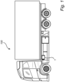
- a vehicle 100 comprising an exhaust after treatment system (EATS) 1, according to one example of the present invention, and a combustion engine (not shown), such as an internal combustion engine, arranged upstream of, and fluidly connected to, the EATS 1.
- the vehicle 100 depicted in Fig. 1 is a truck 100 for which the inventive concept which will be described in detail below, is suitable for.
- Fig. 2 shows a schematic sideview of an EATS 1 in accordance with one embodiment of the invention.
- the EATS arrangement 1 comprises a housing 2, a pre-SCR (Selective Catalytic Reduction) insert 3, a PF (Particulate Filter) insert 4, a first main SCR insert 5, a second main SCR insert 6 and an exhaust pipe 7.
- the pre-SCR insert 3 is arranged to receive exhaust gas entering the EATS arrangement 1 and the PF insert 4 is arranged downstream the pre-SCR insert 3.
- a first reductant injector (not shown), such as a urea injector, may be positioned in the exhaust pipe, upstream the EATS arrangement.
- the first and the second main SCR inserts 5,6 are arranged in parallel and downstream the PF insert 4.
- a second reductant injector 8 such as a urea injector, is arranged upstream the first main SCR insert.
- the pre-SCR insert 3, the PF insert 4 and the first and the second main SCR inserts 5,6 are arranged in the housing 2 and are each removably mounted in the housing 2 such that each insert may be removed separately from the housing 2.
- the respective insert 3,4,5,6 is provided with a respective lid 9,10,11,12 to enable opening and removal of the inserts 3,4,5,6 separately.
- the pre-SCR insert 3 in addition to a pre-SCR unit 3a, comprises an Oxidation Catalyst (OC) 3b for oxidizing carbon monoxide, hydrocarbons and diesel particulate matters to CO 2 and H 2 O, such as a Diesel Oxidation Catalyst (DOC).
- OC Oxidation Catalyst
- DOC Diesel Oxidation Catalyst
- the OC 3b is integrated in the pre-SCR insert 3 such that it is removably mounted in the housing 2 together with the pre-SCR unit 3a and removed separately from the housing 2 as one insert with the pre-SCR insert 3. This is however an optional feature to the EATS arrangement of the present disclosure.
- the pre-SCR unit may comprise an Ammonium Slip Catalyst (ASC) being integrated with the pre-SCR insert, such that it is removably mounted in the housing together with the pre-SCR insert and removed separately from the housing as one insert with the pre-SCR insert.
- ASC Ammonium Slip Catalyst
- the pre-SCR insert 3 is mounted along a first geometric axis a1, the PF insert 4 is mounted along a second geometric axis a2, the first main SCR insert is mounted along a third geometric axis a3 and the second main SCR insert is mounted along a fourth geometric axis a4.
- the first geometric axis a1 is parallel with the second geometric axis a2 and the third geometric axis a3 is parallel with the fourth geometrical axis a4.
- the first geometric axis a1 furthermore coincides with the fourth geometric axis a4 and the second geometric axis a2 coincides with the third geometric axis a3, thus providing a tight integration of the inserts inside the EATS-housing 2 while still allowing removal and insertion of the inserts separately.
- the pre-SCR insert 3 is arranged in a pre-SCR insert cylinder 13 within the housing 2
- the OC insert 4 is arranged in an OC insert cylinder 14 within the housing 2
- the first and second main SCR inserts 5,6 are also arranged in a respective first and second main SCR insert cylinder 15,16 within the housing 2.
- the respective insert 3,4,5,6 within their respective cylinder 13,14,15,16 is removably mounted with a respective clamp 30,40,50,60, securing the inserts 3,4,5,6 to the housing 2.
- the clamps 30,40,50,60 in Fig. 2 each comprises an encircling band having a circumference that is adjustable with a screw, a further alternative is an excenter lock.
- the clamps 30,40,50,60 thus secures an external portion of the respective insert 3,4,5,6 by means of a frictional force resulting from the tightening of the respective clamp 30,40,50,60.
- a gasket 31,41,51,61 is arranged between the respective clamp 30,40,50,60 and the respective insert 3,4,5,6 within their respective cylinder 13,14,15,16 to provide sealing of the housing 2.
- the inserts 3,4,5,6 may alternatively be removably attached to the housing via a bolted flange joint.
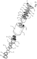
- each of the pre-SCR (Selective Catalytic Reduction) insert 3, the PF (Particulate Filter) insert 4, the first main SCR insert 5, the second main SCR insert 6 may be separately removed from the housing 2, such as for maintenance or exchange, as illustrated in Fig. 3 .
- the EATS arrangement 1 may, as illustrated in Fig. 3 , may comprise one or more electrical heaters 32,42 removably mounted in the housing 2.
- a first electrical heater 32 is arranged upstream the pre-SCR 3 and a second electrical heater 42 is arranged downstream the PF insert 4.
- the first and second heaters 32,42 may optionally be mounted by a respective clamp or alternatively be mounted onto the respective lid 9,10, such that they are removable from the housing 2 as one unit with the lid 9,10.
- Fig. 4 is a cross-sectional view of the EATS arrangement 1 shown in Figs. 2 and 3 and illustrates the exhaust gas flow.
- the pre-SCR 3 is located close to the inlet of the exhaust pipe 7.
- the PF 4 is provided for removing diesel particulate matter or soot from the exhaust gas.
- a reductant injector 8 is arranged for introducing a fluid reductant, such as urea, into a reductant mixpipe 8a.
- a swirl mixer is provided for mixing the fluid reductant with the exhaust gas in the reductant mixpipe 8a.
- the first and second main SCR inserts 5,6 are arranged downstream the reductant injector 8.
- the liquid reductant is stored in a tank (not shown) and pressurized by a pump (not shown).
- the pump is controlled so as to adjust the amount of liquid reductant injected so that a proper amount is added to the exhaust gas flow depending on the operation conditions of the engine (shown in Fig. 1 ).
- the EATS may be used for cleaning exhaust gases of other engines than diesel engines.
- the present EATS may be used to clean exhaust gases, e.g. by converting NOx emissions, from the exhaust of internal combustion engines using petrol, CNG (Compressed Natural Gas), LPG (Liquified Pressurized Gas), DME (DiMethylEther), and/or H2 (Hydrogen) as fuel.
- the engine system may comprise another combustion engine than a diesel engine, e.g. a hydrogen engine.
Landscapes
- Engineering & Computer Science (AREA)
- Chemical & Material Sciences (AREA)
- Chemical Kinetics & Catalysis (AREA)
- Combustion & Propulsion (AREA)
- Mechanical Engineering (AREA)
- General Engineering & Computer Science (AREA)
- Health & Medical Sciences (AREA)
- Toxicology (AREA)
- Exhaust Gas After Treatment (AREA)
Abstract
Description
- The present invention relates to an Exhaust Aftertreatment system (EATS). The invention also relates to a vehicle comprising such EATS.
- Today, in order to fulfill current emission legislation, more or less all vehicles with an Internal Combustion Engine (ICE) are provided with an Exhaust gas Aftertreatment System (EATS) comprising a catalytic converter.
- In such EATS arrangements a selective catalytic reduction system (SCR) is generally used. These systems use liquid reducing agents such as ammonia, urea, and the like. The reducing agent is sprayed into the SCR through a nozzle, or the like, and a chemical reaction is provided between the exhaust from the engine and the reductant, which reduces the amount of NOx ultimately discharged from the EATS. The EATS may furthermore include a Particular Filter (PF), such as a Diesel Particular Filter (DPF) for reducing the particulate matter emissions from the engine exhaust gases.
- The EATS generally consists of a tubular, longitudinal body with an inlet and an outlet, wherein the inlet is arranged on the exhaust side of the ICE, for receiving exhaust gas emissions from the ICE, and an outlet is arranged for discharging exhaust gas emissions treated in the catalytic converter. The inlet is in flow communication with the outlet.
- The next step in emission legislation (EuroVII) for trucks and busses adds very strict requirements on the aftertreatment system for reducing very small particulates (PN10) and gaseous emissions like NOx. There is also a desire to improve the acoustic performance of the EATS-muffler.
- Several technologies have been proposed for meeting the new requirements, including highly efficient particulate filter(s), dual SCR-systems with dual urea dosing and electrical heaters. For best acoustic performance and for meeting packaging constraints, these components are normally integrated into the Exhaust Aftertreatment Muffler (EATS-muffler). These components are all expensive and are also subject for ageing and deterioration over time.
- In view of the above, it is an object of the present disclousure to provide a compact EATS arrangements with an improved space optimization and an improved maintanence to prolong the lifetime in an easy and cost-efficient manner.
- It is an object of the present disclosure to provide an EATS arrangement that at least partially overcomes the above-described deficiencies. This is achieved by an Exhaust Aftertreatment System (EATS) arrangement according to
claim 1 and/or a vehicle comprising the EATS arrangement according toclaim 14. - According to a first aspect, there is provided an Exhaust Aftertreatment System (EATS) arrangement comprising a housing, a pre-SCR (Selective Catalytic Reduction) insert, a PF (Particulate Filter) insert, a first main SCR insert and an exhaust pipe, the pre-SCR insert being arranged to receive exhaust gas entering the EATS arrangement, the PF insert being arranged downstream the pre-SCR insert and the first main SCR insert being arranged downstream the PF insert, wherein the pre-SCR insert, the PF insert and the first main SCR insert are arranged in the housing and are each removably mounted in the housing such that each insert may be removed separately from the housing, the pre-SCR insert being mounted along a first geometric axis, the PF insert being mounted along a second geometric axis and the first main SCR insert is mounted along a third geometric axis, the first geometric axis being parallel with the second geometric axis and the third geometric axis is parallel with the first and the second geometric axis or alternatively coincides with either one of the first and the second geometric axis and is parallel with the other one of the first and the second geometric axis.
- The next step in emission legislation (EuroVII) for trucks and busses adds very strict requirements on the aftertreatment system for reducing very small particulates (PN10) and gaseous emissions like NOx. There will also be increased requirements on in-use measurements and fulfilment as well as longer durability requirement. It is therefore an important advantage that the individual inserts can be individually maintained or exchanged in the EATS according to the present disclosure in a cost-efficient and easy manner.
- Furthermore, to fulfil the requirements, larger and more components which need to be at certain positions in relation to each other are required in the EATS arrangement. The EATS arrangement according to the present disclousure meets the contradictory requirement of tight integration inside the EATS-housing while enabling maintainability and separate exchange of the inserts.
- The Particulate Filter (PF) may optionally be a Diesel Particular Filter (DPF).
- The EATS arrangement may comprise a second main SCR insert being arranged in parallel with the first main SCR insert, the second main SCR insert being separately removably mounted in the housing. Such arrangement provides the EATS arrangement with an enhanced nitrogen oxide converting capacity having a tight integration inside the EATS-housing while still allowing removal and insertion of the inserts.
- The second main SCR insert is mounted along a fourth geometric axis, the fourth geometric axis being parallel with the third geometric axis. Such arrangement enables an enhanced nitrogen oxide converting capacity while improving the space optimization and the maintenance of the inserts in a cost efficient and easy manner.
- The third geometric axis may coincide with the second geometric axis and the fourth geometric axis may coincide with the first geometric axis. Such arrangement enables an enhanced nitrogen oxide converting capacity while improving the space optimization and the maintenance of the inserts in a cost efficient and easy manner.
- Optionally, an Oxidation Catalyst (OC), such as a Diesel Oxidation Catalyst (DOC), may be integrated with the pre-SCR insert, such that it is removably mounted in the housing together with the pre-SCR insert and removed separately from the housing as one insert with the pre-SCR insert. Alternatively, an Ammonium Slip Catalyst (ASC) may be integrated with the pre-SCR insert, such that it is removably mounted in the housing together with the pre-SCR insert and removed separately from the housing as one insert with the pre-SCR insert.
- Optionally, an OC unit, such as a DOC unit, may be integrated with the PF insert, such that it is removably mounted in the housing together with the PF insert and removed separately from the housing as one insert with the PF insert.
- The first and/or second main SCR insert may each include a plurality of SCR units, such as a second SCR unit being arranged downstream a first SCR unit in the first and/or second main SCR insert. Alternatively, or additionally, the first and/or second main SCR insert may include a respective ASC, arranged downstream the first and/or second SCR units in the first and/or second main SCR insert.
- One or more, optionally each one, of the pre-SCR insert, the PF insert, the first main SCR insert and if present the second main SCR insert, is removably mounted by a respective clamp, such as a clamp comprising an encircling band having an adjustable circumference.
- The pre-SCR insert, the PF insert, the first main SCR insert and, if present, the second main SCR insert, may be arranged at a respective wall section of the housing and each one of the respective wall sections is an openable wall section, allowing access to the respective inserts.
- The pre-SCR insert, the PF insert, the first main SCR insert and, if present, the second main SCR insert, may each be removably mounted to a respective wall section of the housing.
- A first reductant injector, such as a urea injector may be positioned in the exhaust pipe, upstream the EATS arrangement. A second reductant injector, such as a urea injector, may be arranged upstream the first main SCR insert.
- The housing may comprise a first heater, such as an electrical heater, being removably mounted in the housing.
- The pre-SCR insert may comprise a lid, the heater being positioned upstream the pre-SCR insert and wherein the heater is mounted to the lid and is removable from the EATS arrangement as one unit with the lid.
- The housing may comprise a second heater, such as an electrical heater, being removably mounted in the housing.
- The PF insert may comprise a lid the heater being positioned downstream the PF insert and wherein the heater is mounted to the lid and is removable from the EATS arrangement as one unit with the lid.
- Alternatively, the heater(s) may be removably mounted to the housing with a respective clamp.
- Each one of the pre-SCR insert, the PF insert, the first main SCR insert and, if present, the second main SCR insert may have the same diameter, or at least a diameter which does not differ more than ± 10% from the diameters of each one of the other inserts, as measured perpendicular to the geometric axis along which the respective insert is mounted. This provides a uniform arrangement enabling a tight fitting of the housing around the respective insert, as seen in the transverse direction of the EATS.
- The pre-SCR insert and the PF insert may have the same length, or at least a length which does not differ more than ± 20% from the length of the other insert, as measured along the geometric axis along which the respective insert is mounted. This provides a uniform arrangement enabling a tight fitting of the housing around the respective insert, as seen in the longitudinal direction of the EATS.
- The EATS may comprise a second main SCR and where the first main SCR insert and the second main SCR insert may have the same length, or at least a length which does not differ more than ± 10% from the length of the other insert, as measured along the geometric axis along which the respective insert is mounted.
- According to a second aspect, the present disclosure relates to a vehicle comprising an EATS arrangement according to the first aspect.
- Further features of, and advantages with, the present invention will become apparent when studying the appended claims and the following description. The skilled person realize that different features of the present invention may be combined to create embodiments other than those described in the following, without departing from the scope of the present invention.
- The above, as well as additional objects, features and advantages of the present invention, will be better understood through the following illustrative and non-limiting detailed description of exemplary embodiments of the present invention, wherein:
-
Fig. 1 is a side view of a vehicle comprising an Exhaust gas after Treatment System (EATS) according to an example of the present invention; -
Fig. 2 is a schematic sideview of an EATS according to an example of the present invention; -
Fig. 3 shows a sideview of the EATS according toFig. 2 with the EATS inserts being separately removed from the EATS; and -
Fig. 4 shows a cross section of the EATS according to the present invention including the flow direction of the exhaust gas. - The present disclosure will now be described more fully hereinafter with reference to the accompanying drawings, in which exemplary embodiments are shown. The disclosure may, however, be embodied in many different forms and should not be construed as limited to the embodiments set forth herein; rather, these embodiments are provided for thoroughness and completeness. Like reference character refer to like elements throughout the description.
- With particular reference to
Fig. 1 , there is provided avehicle 100 comprising an exhaust after treatment system (EATS) 1, according to one example of the present invention, and a combustion engine (not shown), such as an internal combustion engine, arranged upstream of, and fluidly connected to, theEATS 1. Thevehicle 100 depicted inFig. 1 is atruck 100 for which the inventive concept which will be described in detail below, is suitable for. -
Fig. 2 shows a schematic sideview of anEATS 1 in accordance with one embodiment of the invention. In the non-limiting example ofFig. 2 , theEATS arrangement 1 comprises ahousing 2, a pre-SCR (Selective Catalytic Reduction)insert 3, a PF (Particulate Filter)insert 4, a firstmain SCR insert 5, a secondmain SCR insert 6 and anexhaust pipe 7. Thepre-SCR insert 3 is arranged to receive exhaust gas entering theEATS arrangement 1 and thePF insert 4 is arranged downstream thepre-SCR insert 3. A first reductant injector (not shown), such as a urea injector, may be positioned in the exhaust pipe, upstream the EATS arrangement. - The first and the second main SCR inserts 5,6 are arranged in parallel and downstream the
PF insert 4. Asecond reductant injector 8, such as a urea injector, is arranged upstream the first main SCR insert. - The
pre-SCR insert 3, thePF insert 4 and the first and the second main SCR inserts 5,6 are arranged in thehousing 2 and are each removably mounted in thehousing 2 such that each insert may be removed separately from thehousing 2. Therespective insert respective lid inserts EATS 1 and in an alternative embodiment theinserts - In this embodiment the
pre-SCR insert 3, in addition to apre-SCR unit 3a, comprises an Oxidation Catalyst (OC) 3b for oxidizing carbon monoxide, hydrocarbons and diesel particulate matters to CO2 and H2O, such as a Diesel Oxidation Catalyst (DOC). TheOC 3b is integrated in thepre-SCR insert 3 such that it is removably mounted in thehousing 2 together with thepre-SCR unit 3a and removed separately from thehousing 2 as one insert with thepre-SCR insert 3. This is however an optional feature to the EATS arrangement of the present disclosure. Alternatively, to an OC unit, the pre-SCR unit may comprise an Ammonium Slip Catalyst (ASC) being integrated with the pre-SCR insert, such that it is removably mounted in the housing together with the pre-SCR insert and removed separately from the housing as one insert with the pre-SCR insert. - The
pre-SCR insert 3 is mounted along a first geometric axis a1, thePF insert 4 is mounted along a second geometric axis a2, the first main SCR insert is mounted along a third geometric axis a3 and the second main SCR insert is mounted along a fourth geometric axis a4. The first geometric axis a1 is parallel with the second geometric axis a2 and the third geometric axis a3 is parallel with the fourth geometrical axis a4. - In this embodiment, the first geometric axis a1 furthermore coincides with the fourth geometric axis a4 and the second geometric axis a2 coincides with the third geometric axis a3, thus providing a tight integration of the inserts inside the EATS-
housing 2 while still allowing removal and insertion of the inserts separately. - The
pre-SCR insert 3 is arranged in apre-SCR insert cylinder 13 within thehousing 2, theOC insert 4 is arranged in anOC insert cylinder 14 within thehousing 2 and the first and second main SCR inserts 5,6 are also arranged in a respective first and second mainSCR insert cylinder housing 2. - The
respective insert respective cylinder respective clamp inserts housing 2. The clamps 30,40,50,60 inFig. 2 each comprises an encircling band having a circumference that is adjustable with a screw, a further alternative is an excenter lock. The clamps 30,40,50,60 thus secures an external portion of therespective insert respective clamp gasket respective clamp respective insert respective cylinder housing 2. Theinserts - By removing or opening of the
respective lid respective clamp insert 3, the PF (Particulate Filter)insert 4, the firstmain SCR insert 5, the secondmain SCR insert 6 may be separately removed from thehousing 2, such as for maintenance or exchange, as illustrated inFig. 3 . - The
EATS arrangement 1 may, as illustrated inFig. 3 , may comprise one or moreelectrical heaters housing 2. InFig. 3 , a firstelectrical heater 32 is arranged upstream the pre-SCR 3 and a secondelectrical heater 42 is arranged downstream thePF insert 4. The first andsecond heaters respective lid housing 2 as one unit with thelid -
Fig. 4 is a cross-sectional view of theEATS arrangement 1 shown inFigs. 2 and3 and illustrates the exhaust gas flow. When the internal combustion engine (not shown) is running, exhaust gas exhausted from the engine passes through theexhaust pipe 7 in a flow direction indicated by the arrows inFig. 4 . Thepre-SCR 3 is located close to the inlet of theexhaust pipe 7. Downstream thecatalyst 3, thePF 4 is provided for removing diesel particulate matter or soot from the exhaust gas. Downstream thePF 4, areductant injector 8 is arranged for introducing a fluid reductant, such as urea, into a reductant mixpipe 8a. Optionally, a swirl mixer is provided for mixing the fluid reductant with the exhaust gas in the reductant mixpipe 8a. - The first and second main SCR inserts 5,6 are arranged downstream the
reductant injector 8. The liquid reductant is stored in a tank (not shown) and pressurized by a pump (not shown). The pump is controlled so as to adjust the amount of liquid reductant injected so that a proper amount is added to the exhaust gas flow depending on the operation conditions of the engine (shown inFig. 1 ). - It is to be understood that the present invention is not limited to the embodiments described above and illustrated in the drawings; rather, the skilled person will recognize that many changes and modifications may be made within the scope of the appended claims. For example, the EATS may be used for cleaning exhaust gases of other engines than diesel engines. For example, the present EATS may be used to clean exhaust gases, e.g. by converting NOx emissions, from the exhaust of internal combustion engines using petrol, CNG (Compressed Natural Gas), LPG (Liquified Pressurized Gas), DME (DiMethylEther), and/or H2 (Hydrogen) as fuel. Thus, the engine system may comprise another combustion engine than a diesel engine, e.g. a hydrogen engine.
Claims (15)
Priority Applications (2)
| Application Number | Priority Date | Filing Date | Title |
|---|---|---|---|
| EP22175489.8A EP4283099B1 (en) | 2022-05-25 | 2022-05-25 | An exhaust aftertreatment system (eats) |
| US18/322,276 US12209522B2 (en) | 2022-05-25 | 2023-05-23 | Exhaust aftertreatment system (EATS) |
Applications Claiming Priority (1)
| Application Number | Priority Date | Filing Date | Title |
|---|---|---|---|
| EP22175489.8A EP4283099B1 (en) | 2022-05-25 | 2022-05-25 | An exhaust aftertreatment system (eats) |
Publications (3)
| Publication Number | Publication Date |
|---|---|
| EP4283099A1 true EP4283099A1 (en) | 2023-11-29 |
| EP4283099C0 EP4283099C0 (en) | 2025-01-29 |
| EP4283099B1 EP4283099B1 (en) | 2025-01-29 |
Family
ID=81850078
Family Applications (1)
| Application Number | Title | Priority Date | Filing Date |
|---|---|---|---|
| EP22175489.8A Active EP4283099B1 (en) | 2022-05-25 | 2022-05-25 | An exhaust aftertreatment system (eats) |
Country Status (2)
| Country | Link |
|---|---|
| US (1) | US12209522B2 (en) |
| EP (1) | EP4283099B1 (en) |
Cited By (1)
| Publication number | Priority date | Publication date | Assignee | Title |
|---|---|---|---|---|
| DE102024210369B3 (en) | 2024-10-28 | 2026-04-02 | Tenneco Gmbh | An assembly for an exhaust aftertreatment device, a heating system, the exhaust aftertreatment device, a method for using the assembly, and a method for replacing a heating element in the exhaust aftertreatment device. |
Citations (6)
| Publication number | Priority date | Publication date | Assignee | Title |
|---|---|---|---|---|
| WO2014008930A1 (en) * | 2012-07-10 | 2014-01-16 | Swenox Ab | Apparatus for treating an exhaust gas stream with removable module |
| WO2014084537A1 (en) * | 2012-11-27 | 2014-06-05 | 주식회사 파나시아 | Scr reactor having structure for minimizing volume thereof |
| FR3098854A1 (en) * | 2019-07-15 | 2021-01-22 | Faurecia Systemes D'echappement | Exhaust gas depollution system |
| DE102020007553A1 (en) * | 2020-12-10 | 2021-03-18 | FEV Group GmbH | Exhaust box for an exhaust aftertreatment system |
| WO2021104604A1 (en) * | 2019-11-25 | 2021-06-03 | Volvo Truck Corporation | Method for unblocking pores in a selective catalytic reduction catalyst |
| WO2021225824A1 (en) * | 2020-05-08 | 2021-11-11 | Cummins Emission Solutions Inc. | Configurable aftertreatment systems including a housing |
Family Cites Families (9)
| Publication number | Priority date | Publication date | Assignee | Title |
|---|---|---|---|---|
| JP2008255858A (en) * | 2007-04-03 | 2008-10-23 | Yanmar Co Ltd | Black smoke eliminating device for diesel engine |
| US8646259B2 (en) | 2011-04-08 | 2014-02-11 | GM Global Technology Operations LLC | Electronically heated selective catalytic reduction (SCR) device |
| JP2014231748A (en) * | 2013-05-28 | 2014-12-11 | 三菱ふそうトラック・バス株式会社 | Exhaust gas purification device |
| KR20170005932A (en) * | 2015-07-06 | 2017-01-17 | 주식회사 이알지 | Gas filtering device |
| JP2018123776A (en) * | 2017-02-02 | 2018-08-09 | トヨタ自動車株式会社 | Exhaust gas purification device for internal combustion engine |
| US20180334939A1 (en) * | 2017-05-17 | 2018-11-22 | GM Global Technology Operations LLC | Electric heaters comprising corrosion resistant metals and selective catalytic reduction devices utilizing the same |
| CN107780998B (en) | 2017-10-18 | 2021-01-15 | 潍柴动力股份有限公司 | Universal integrated DOC-DPF-SCR post-treatment device |
| US11156143B2 (en) * | 2019-10-28 | 2021-10-26 | Caterpillar Inc. | Aftertreatment system and method |
| US11143078B2 (en) | 2019-12-17 | 2021-10-12 | Caterpillar Inc. | Aftertreatment system and method |
-
2022
- 2022-05-25 EP EP22175489.8A patent/EP4283099B1/en active Active
-
2023
- 2023-05-23 US US18/322,276 patent/US12209522B2/en active Active
Patent Citations (6)
| Publication number | Priority date | Publication date | Assignee | Title |
|---|---|---|---|---|
| WO2014008930A1 (en) * | 2012-07-10 | 2014-01-16 | Swenox Ab | Apparatus for treating an exhaust gas stream with removable module |
| WO2014084537A1 (en) * | 2012-11-27 | 2014-06-05 | 주식회사 파나시아 | Scr reactor having structure for minimizing volume thereof |
| FR3098854A1 (en) * | 2019-07-15 | 2021-01-22 | Faurecia Systemes D'echappement | Exhaust gas depollution system |
| WO2021104604A1 (en) * | 2019-11-25 | 2021-06-03 | Volvo Truck Corporation | Method for unblocking pores in a selective catalytic reduction catalyst |
| WO2021225824A1 (en) * | 2020-05-08 | 2021-11-11 | Cummins Emission Solutions Inc. | Configurable aftertreatment systems including a housing |
| DE102020007553A1 (en) * | 2020-12-10 | 2021-03-18 | FEV Group GmbH | Exhaust box for an exhaust aftertreatment system |
Cited By (1)
| Publication number | Priority date | Publication date | Assignee | Title |
|---|---|---|---|---|
| DE102024210369B3 (en) | 2024-10-28 | 2026-04-02 | Tenneco Gmbh | An assembly for an exhaust aftertreatment device, a heating system, the exhaust aftertreatment device, a method for using the assembly, and a method for replacing a heating element in the exhaust aftertreatment device. |
Also Published As
| Publication number | Publication date |
|---|---|
| EP4283099C0 (en) | 2025-01-29 |
| US20230383683A1 (en) | 2023-11-30 |
| US12209522B2 (en) | 2025-01-28 |
| EP4283099B1 (en) | 2025-01-29 |
Similar Documents
| Publication | Publication Date | Title |
|---|---|---|
| CN102741517B (en) | Exhaust gas aftertreatment system | |
| US8635861B2 (en) | Exhaust aftertreatment system | |
| US20080141662A1 (en) | Fluid injecting and mixing systems for exhaust after-treatment devices | |
| US8713922B2 (en) | Engine exhaust purification device | |
| US20110167810A1 (en) | Flow device for exhaust treatment system | |
| CN115126586B (en) | Exhaust aftertreatment units for cleaning exhaust gas | |
| US20100326059A1 (en) | Selective catalytic reduction exhaust aftertreatment system and engine incorporating the same | |
| GB2558311A (en) | Flow distribution arrangement for aftertreatment of exhaust gas | |
| US11933210B2 (en) | Exhaust aftertreatment unit for cleaning exhaust gases | |
| JP5258426B2 (en) | Engine exhaust purification system | |
| US12209522B2 (en) | Exhaust aftertreatment system (EATS) | |
| US10329990B2 (en) | Asymmetric catalyst cone for swirl induction of exhaust gas flow | |
| US12571338B2 (en) | Engine system comprising a hydrogen combustion engine | |
| JP2018021514A (en) | Mixer unit and exhaust system | |
| US11834978B2 (en) | Systems and methods for decreasing time to reach light-off temperature | |
| US12553372B2 (en) | Aftertreatment system for locomotive | |
| CN217176734U (en) | Diesel engine close coupling exhaust aftertreatment and urea double-spraying device thereof | |
| US11454151B2 (en) | Method for cleaning a component of an exhaust aftertreatment system and an exhaust system | |
| GB2611767A (en) | Cleaning device and method for cleaning an SCR catalyst of an exhaust system | |
| SE541093C2 (en) | Dosing system for reduction agent |
Legal Events
| Date | Code | Title | Description |
|---|---|---|---|
| PUAI | Public reference made under article 153(3) epc to a published international application that has entered the european phase |
Free format text: ORIGINAL CODE: 0009012 |
|
| STAA | Information on the status of an ep patent application or granted ep patent |
Free format text: STATUS: THE APPLICATION HAS BEEN PUBLISHED |
|
| AK | Designated contracting states |
Kind code of ref document: A1 Designated state(s): AL AT BE BG CH CY CZ DE DK EE ES FI FR GB GR HR HU IE IS IT LI LT LU LV MC MK MT NL NO PL PT RO RS SE SI SK SM TR |
|
| STAA | Information on the status of an ep patent application or granted ep patent |
Free format text: STATUS: REQUEST FOR EXAMINATION WAS MADE |
|
| 17P | Request for examination filed |
Effective date: 20240515 |
|
| RBV | Designated contracting states (corrected) |
Designated state(s): AL AT BE BG CH CY CZ DE DK EE ES FI FR GB GR HR HU IE IS IT LI LT LU LV MC MK MT NL NO PL PT RO RS SE SI SK SM TR |
|
| GRAP | Despatch of communication of intention to grant a patent |
Free format text: ORIGINAL CODE: EPIDOSNIGR1 |
|
| STAA | Information on the status of an ep patent application or granted ep patent |
Free format text: STATUS: GRANT OF PATENT IS INTENDED |
|
| INTG | Intention to grant announced |
Effective date: 20240909 |
|
| RIC1 | Information provided on ipc code assigned before grant |
Ipc: F01N 13/00 20100101ALI20240830BHEP Ipc: F01N 3/20 20060101ALI20240830BHEP Ipc: F01N 3/021 20060101AFI20240830BHEP |
|
| GRAS | Grant fee paid |
Free format text: ORIGINAL CODE: EPIDOSNIGR3 |
|
| GRAA | (expected) grant |
Free format text: ORIGINAL CODE: 0009210 |
|
| STAA | Information on the status of an ep patent application or granted ep patent |
Free format text: STATUS: THE PATENT HAS BEEN GRANTED |
|
| AK | Designated contracting states |
Kind code of ref document: B1 Designated state(s): AL AT BE BG CH CY CZ DE DK EE ES FI FR GB GR HR HU IE IS IT LI LT LU LV MC MK MT NL NO PL PT RO RS SE SI SK SM TR |
|
| REG | Reference to a national code |
Ref country code: GB Ref legal event code: FG4D |
|
| REG | Reference to a national code |
Ref country code: CH Ref legal event code: EP |
|
| REG | Reference to a national code |
Ref country code: DE Ref legal event code: R096 Ref document number: 602022009971 Country of ref document: DE |
|
| REG | Reference to a national code |
Ref country code: IE Ref legal event code: FG4D |
|
| U01 | Request for unitary effect filed |
Effective date: 20250205 |
|
| U07 | Unitary effect registered |
Designated state(s): AT BE BG DE DK EE FI FR IT LT LU LV MT NL PT RO SE SI Effective date: 20250211 |
|
| U20 | Renewal fee for the european patent with unitary effect paid |
Year of fee payment: 4 Effective date: 20250526 |
|
| PG25 | Lapsed in a contracting state [announced via postgrant information from national office to epo] |
Ref country code: RS Free format text: LAPSE BECAUSE OF FAILURE TO SUBMIT A TRANSLATION OF THE DESCRIPTION OR TO PAY THE FEE WITHIN THE PRESCRIBED TIME-LIMIT Effective date: 20250429 |
|
| PG25 | Lapsed in a contracting state [announced via postgrant information from national office to epo] |
Ref country code: PL Free format text: LAPSE BECAUSE OF FAILURE TO SUBMIT A TRANSLATION OF THE DESCRIPTION OR TO PAY THE FEE WITHIN THE PRESCRIBED TIME-LIMIT Effective date: 20250129 |
|
| PG25 | Lapsed in a contracting state [announced via postgrant information from national office to epo] |
Ref country code: ES Free format text: LAPSE BECAUSE OF FAILURE TO SUBMIT A TRANSLATION OF THE DESCRIPTION OR TO PAY THE FEE WITHIN THE PRESCRIBED TIME-LIMIT Effective date: 20250129 |
|
| PG25 | Lapsed in a contracting state [announced via postgrant information from national office to epo] |
Ref country code: IS Free format text: LAPSE BECAUSE OF FAILURE TO SUBMIT A TRANSLATION OF THE DESCRIPTION OR TO PAY THE FEE WITHIN THE PRESCRIBED TIME-LIMIT Effective date: 20250529 Ref country code: NO Free format text: LAPSE BECAUSE OF FAILURE TO SUBMIT A TRANSLATION OF THE DESCRIPTION OR TO PAY THE FEE WITHIN THE PRESCRIBED TIME-LIMIT Effective date: 20250429 |
|
| PG25 | Lapsed in a contracting state [announced via postgrant information from national office to epo] |
Ref country code: HR Free format text: LAPSE BECAUSE OF FAILURE TO SUBMIT A TRANSLATION OF THE DESCRIPTION OR TO PAY THE FEE WITHIN THE PRESCRIBED TIME-LIMIT Effective date: 20250129 |
|
| PG25 | Lapsed in a contracting state [announced via postgrant information from national office to epo] |
Ref country code: GR Free format text: LAPSE BECAUSE OF FAILURE TO SUBMIT A TRANSLATION OF THE DESCRIPTION OR TO PAY THE FEE WITHIN THE PRESCRIBED TIME-LIMIT Effective date: 20250430 |
|
| PG25 | Lapsed in a contracting state [announced via postgrant information from national office to epo] |
Ref country code: SM Free format text: LAPSE BECAUSE OF FAILURE TO SUBMIT A TRANSLATION OF THE DESCRIPTION OR TO PAY THE FEE WITHIN THE PRESCRIBED TIME-LIMIT Effective date: 20250129 |
|
| PG25 | Lapsed in a contracting state [announced via postgrant information from national office to epo] |
Ref country code: CZ Free format text: LAPSE BECAUSE OF FAILURE TO SUBMIT A TRANSLATION OF THE DESCRIPTION OR TO PAY THE FEE WITHIN THE PRESCRIBED TIME-LIMIT Effective date: 20250129 |
|
| PG25 | Lapsed in a contracting state [announced via postgrant information from national office to epo] |
Ref country code: SK Free format text: LAPSE BECAUSE OF FAILURE TO SUBMIT A TRANSLATION OF THE DESCRIPTION OR TO PAY THE FEE WITHIN THE PRESCRIBED TIME-LIMIT Effective date: 20250129 |
|
| PLBE | No opposition filed within time limit |
Free format text: ORIGINAL CODE: 0009261 |
|
| STAA | Information on the status of an ep patent application or granted ep patent |
Free format text: STATUS: NO OPPOSITION FILED WITHIN TIME LIMIT |
|
| REG | Reference to a national code |
Ref country code: CH Ref legal event code: L10 Free format text: ST27 STATUS EVENT CODE: U-0-0-L10-L00 (AS PROVIDED BY THE NATIONAL OFFICE) Effective date: 20251210 |
|
| REG | Reference to a national code |
Ref country code: CH Ref legal event code: H13 Free format text: ST27 STATUS EVENT CODE: U-0-0-H10-H13 (AS PROVIDED BY THE NATIONAL OFFICE) Effective date: 20251223 |
|
| 26N | No opposition filed |
Effective date: 20251030 |
|
| PG25 | Lapsed in a contracting state [announced via postgrant information from national office to epo] |
Ref country code: CH Free format text: LAPSE BECAUSE OF NON-PAYMENT OF DUE FEES Effective date: 20250531 |
|
| PG25 | Lapsed in a contracting state [announced via postgrant information from national office to epo] |
Ref country code: MC Free format text: LAPSE BECAUSE OF FAILURE TO SUBMIT A TRANSLATION OF THE DESCRIPTION OR TO PAY THE FEE WITHIN THE PRESCRIBED TIME-LIMIT Effective date: 20250129 |
|
| PG25 | Lapsed in a contracting state [announced via postgrant information from national office to epo] |
Ref country code: IE Free format text: LAPSE BECAUSE OF NON-PAYMENT OF DUE FEES Effective date: 20250525 |