EP4282836A1 - Surface texture enhanced glass-ceramic matrix composite heat exchanger - Google Patents
Surface texture enhanced glass-ceramic matrix composite heat exchanger Download PDFInfo
- Publication number
- EP4282836A1 EP4282836A1 EP23170171.5A EP23170171A EP4282836A1 EP 4282836 A1 EP4282836 A1 EP 4282836A1 EP 23170171 A EP23170171 A EP 23170171A EP 4282836 A1 EP4282836 A1 EP 4282836A1
- Authority
- EP
- European Patent Office
- Prior art keywords
- matrix material
- heat exchanger
- glass matrix
- reinforcing fibers
- core
- Prior art date
- Legal status (The legal status is an assumption and is not a legal conclusion. Google has not performed a legal analysis and makes no representation as to the accuracy of the status listed.)
- Granted
Links
Images

Classifications
-
- F—MECHANICAL ENGINEERING; LIGHTING; HEATING; WEAPONS; BLASTING
- F28—HEAT EXCHANGE IN GENERAL
- F28F—DETAILS OF HEAT-EXCHANGE AND HEAT-TRANSFER APPARATUS, OF GENERAL APPLICATION
- F28F21/00—Constructions of heat-exchange apparatus characterised by the selection of particular materials
- F28F21/04—Constructions of heat-exchange apparatus characterised by the selection of particular materials of ceramic; of concrete; of natural stone
-
- C—CHEMISTRY; METALLURGY
- C03—GLASS; MINERAL OR SLAG WOOL
- C03B—MANUFACTURE, SHAPING, OR SUPPLEMENTARY PROCESSES
- C03B19/00—Other methods of shaping glass
- C03B19/02—Other methods of shaping glass by casting molten glass, e.g. injection moulding
-
- C—CHEMISTRY; METALLURGY
- C03—GLASS; MINERAL OR SLAG WOOL
- C03B—MANUFACTURE, SHAPING, OR SUPPLEMENTARY PROCESSES
- C03B19/00—Other methods of shaping glass
- C03B19/02—Other methods of shaping glass by casting molten glass, e.g. injection moulding
- C03B19/025—Other methods of shaping glass by casting molten glass, e.g. injection moulding by injection moulding, e.g. extrusion
-
- C—CHEMISTRY; METALLURGY
- C03—GLASS; MINERAL OR SLAG WOOL
- C03B—MANUFACTURE, SHAPING, OR SUPPLEMENTARY PROCESSES
- C03B19/00—Other methods of shaping glass
- C03B19/06—Other methods of shaping glass by sintering, e.g. by cold isostatic pressing of powders and subsequent sintering, by hot pressing of powders, by sintering slurries or dispersions not undergoing a liquid phase reaction
- C03B19/063—Other methods of shaping glass by sintering, e.g. by cold isostatic pressing of powders and subsequent sintering, by hot pressing of powders, by sintering slurries or dispersions not undergoing a liquid phase reaction by hot-pressing powders
-
- C—CHEMISTRY; METALLURGY
- C03—GLASS; MINERAL OR SLAG WOOL
- C03C—CHEMICAL COMPOSITION OF GLASSES, GLAZES OR VITREOUS ENAMELS; SURFACE TREATMENT OF GLASS; SURFACE TREATMENT OF FIBRES OR FILAMENTS MADE FROM GLASS, MINERALS OR SLAGS; JOINING GLASS TO GLASS OR OTHER MATERIALS
- C03C14/00—Glass compositions containing a non-glass component, e.g. compositions containing fibres, filaments, whiskers, platelets, or the like, dispersed in a glass matrix
- C03C14/002—Glass compositions containing a non-glass component, e.g. compositions containing fibres, filaments, whiskers, platelets, or the like, dispersed in a glass matrix the non-glass component being in the form of fibres, filaments, yarns, felts or woven material
-
- C—CHEMISTRY; METALLURGY
- C03—GLASS; MINERAL OR SLAG WOOL
- C03C—CHEMICAL COMPOSITION OF GLASSES, GLAZES OR VITREOUS ENAMELS; SURFACE TREATMENT OF GLASS; SURFACE TREATMENT OF FIBRES OR FILAMENTS MADE FROM GLASS, MINERALS OR SLAGS; JOINING GLASS TO GLASS OR OTHER MATERIALS
- C03C2214/00—Nature of the non-vitreous component
- C03C2214/02—Fibres; Filaments; Yarns; Felts; Woven material
-
- C—CHEMISTRY; METALLURGY
- C03—GLASS; MINERAL OR SLAG WOOL
- C03C—CHEMICAL COMPOSITION OF GLASSES, GLAZES OR VITREOUS ENAMELS; SURFACE TREATMENT OF GLASS; SURFACE TREATMENT OF FIBRES OR FILAMENTS MADE FROM GLASS, MINERALS OR SLAGS; JOINING GLASS TO GLASS OR OTHER MATERIALS
- C03C2214/00—Nature of the non-vitreous component
- C03C2214/20—Glass-ceramics matrix
-
- C—CHEMISTRY; METALLURGY
- C03—GLASS; MINERAL OR SLAG WOOL
- C03C—CHEMICAL COMPOSITION OF GLASSES, GLAZES OR VITREOUS ENAMELS; SURFACE TREATMENT OF GLASS; SURFACE TREATMENT OF FIBRES OR FILAMENTS MADE FROM GLASS, MINERALS OR SLAGS; JOINING GLASS TO GLASS OR OTHER MATERIALS
- C03C2214/00—Nature of the non-vitreous component
- C03C2214/30—Methods of making the composites
-
- C—CHEMISTRY; METALLURGY
- C03—GLASS; MINERAL OR SLAG WOOL
- C03C—CHEMICAL COMPOSITION OF GLASSES, GLAZES OR VITREOUS ENAMELS; SURFACE TREATMENT OF GLASS; SURFACE TREATMENT OF FIBRES OR FILAMENTS MADE FROM GLASS, MINERALS OR SLAGS; JOINING GLASS TO GLASS OR OTHER MATERIALS
- C03C2214/00—Nature of the non-vitreous component
- C03C2214/34—Nature of the non-vitreous component comprising an impregnation by molten glass step
Definitions
- This disclosure relates generally to heat exchangers and more particularly to heat exchangers made from Ceramic Matrix Composite (CMC).
- CMC Ceramic Matrix Composite
- Heat exchangers are made of many different types of materials. CMC heat exchangers are particularly useful in high temperature environments. However, CMC materials can have a low thermal conductivity, reducing the efficiency of CMC heat exchangers. Therefore, a method of augmenting and enhancing heat transfer in CMC heat exchangers is desired.
- a method of manufacturing a heat exchanger core from glass ceramic matrix composite includes placing one or more reinforcing fibers around one or more mandrels into a mold cavity.
- a glass matrix material infiltrates the one or more reinforcing fibers to produce an infiltrated core and the one or more mandrels are removed to create one or more passages passing through the infiltrated core.
- a heat exchanger in another embodiment, includes one or more tubular regions, and each tubular region of the one or more tubular regions includes a passage with a radially inner surface and a radially outer surface.
- One or more reinforcing fibers is between the radially inner surface and the radially outer surface of each tubular region.
- a glass matrix material infiltrates the one or more reinforcing fibers.
- a first pattern is formed into the radially inner surface of each tubular region and a second pattern is formed into the radially outer surface of each tubular region.
- This disclosure relates to a heat exchanger made from Ceramic Matrix Composite (CMC) materials, and in particular to heat exchangers formed of Glass Ceramic Matrix Composite (G-CMC) materials.
- the heat exchanger has surface features formed from G-CMC materials. The surface features can be protrusions or indentations either internally or externally which break up the flow boundary layer and increase flow turbulence, thereby increasing heat transfer in the heat exchanger.
- the heat exchanger will be discussed below with reference to FIGS. 1-5 .
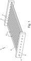
- FIG. 1 is a perspective view of an embodiment of tube sheet heat exchanger 10 formed from G-CMC materials.
- Tube sheet heat exchanger 10 comprises tubular regions 12, flat regions 14, and passageways 16.
- Passageways 16 comprises radially inner part surface 18 and radially outer part surface 20.
- Tube sheet heat exchanger 10 transfers heat from a first fluid to a second fluid.
- the first fluid can be at a higher temperature than the second fluid or vice-versa.
- the first fluid flows over radially outer part surface 20.
- the second fluid flows through passageways 16 and contacts radially inner part surface 18.
- the first fluid flows at an angle relative to the second fluid. The angle can be between 0 and 180 degrees.
- Tubular regions 12 are spaced apart from one another by flat regions 14 and form raised regions between flat regions 14. In some embodiments flat regions 14 are wide. In alternative embodiments, flat regions 14 are substantially narrow. Alternatively, tubular regions 12 can directly abut each other, thus flat regions 14 would substantially not be present.
- Tubular regions 12 house passageways 16.
- Tubular regions 12 are the regions where heat transfer from the first fluid to the second fluid primarily occurs. When present, some heat transfer occurs in flat regions 14.
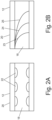
- FIGS. 2A-2B each disclose a cross-sectional view of an embodiment of passageways 16 of tube sheet heat exchanger 10 and will be discussed together.
- FIG 2A is a cross-sectional view of passageway 16 of tube sheet heat exchanger 10 of FIG. 1 taken along line A-A with protrusions 22.
- FIG. 2A includes radially inner part surface 18, radially outer part surface 20, and protrusions 22.
- FIG 2B is a cross-sectional view of passageway 16 of tube sheet heat exchanger 10 of FIG. 1 taken along line A-A, except passageway 16 comprises grooved indentations 23, 24, or 25 instead of protrusions 22.
- FIG. 2B includes radially inner part surface 18, radially outer part surface 20, and grooved indentations 23, 24, or 25.
- a first pattern is formed on radially inner part surface 18 of passageways 16 .
- the first pattern is formed by protrusions 22.
- the first pattern is formed by grooved indentations 23, 24, or 25.
- Grooved indentation 23 has a tight tread spacing whereas grooved indentation 25 has a wide tread spacing.
- Grooved indentation 24 has a tread spacing between the tight tread spacing of grooved indentation 23 and the wide tread spacing of grooved indentation 25.
- the first pattern can be a combination of grooved indentations 23, 24, and 25.
- the first pattern can be a combination of protrusions 22 and grooved indentations 23, 24, or 25 together in the same passageway 16.
- the first pattern can further be any combination of protrusions and/or indentations which modulate a flow of a fluid through passageway 16. Modulation of the flow of the fluid through passageway 16 increases heat transfer from radially inner part surface 18 into the G-CMC material with the heat then conducting to radially outer part surface 20. Modulation of the flow can include breaking up the flow boundary layer and/or inducing mixing and turbulence within passageway 16, thereby in some cases changing a substantially laminar flow to a substantially turbulent flow. Breaking up the flow boundary layer can lead to flow disruption and increased mixing. Further, if turbulent flow is induced heat transfer can occur even more readily as turbulent flow does not have an insulating layer along the radially inner part surface 18.
- Protrusions 22 create turbulent flow by protruding into a flow column in passageway 16 thereby interrupting the flow along radially inner part surface 18.
- Grooved indentations 23, 24, or 25 also create turbulent flow within passageway 16 by altering flow nearest radially inner part surface 18, thereby disrupting the overall flow column in passageway 16. A tighter tread spacing can disrupt the overall flow column more than a wider tread spacing, however this further increases the pressure drop across the passageway 16
- Both protrusions 22 and grooved indentations 23, 24, or 25 alter flow nearest radially inner part surface 18, disrupting the insulation layer which forms in laminar flow. Additionally, both protrusions 22 and grooved indentations 23, 24, or 25 can be formed on radially outer part surface 20.
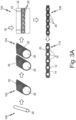
- FIG. 3A is flow diagram of G-CMC component being manufactured using mold 32 with injection sites 33 therein.
- the flow diagram of FIG. 3A includes the steps of providing mandrel 26, forming fiber preform 28 around mandrel 26, injecting fiber preform 28 with glass matrix material 30, removing mandrels 26, and providing the finalized G-CMC component.
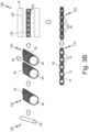
- the flow diagram of FIG. 3B includes the steps of providing mandrel 26, forming fiber preform 28 around mandrel 26, infiltrating fiber preform 28 with glass matrix material 30, hot pressing fiber preform 28 with die set 34, removing mandrels 26, and providing the finalized G-CMC component.
- first step 100 in a possible embodiment of manufacturing the G-CMC component is providing mandrel 26 to a build surface.
- the build surface can be mold 32.
- mandrel 26 is formed of graphite.
- mandrel 26 can be formed of any material know to those of skill in the art to be chemically inert with chosen substate 30.
- Mandrel 26 can have the first pattern discussed above with reference to FIGS. 2A and 2B formed in negative on an outer tooling surface of mandrel 26.
- the first pattern can include tooling surface protrusions or indentations which will form part surface indentations or protrusions, respectively, on radially inner part surface 18 of passageways 16.
- second step 102 of manufacturing the G-CMC component is forming fiber preform 28 around mandrel 26.
- Fiber preform 28 provides a surface for glass matrix material 30 to adhere too.
- Fiber preform 28 also provides reinforcement and improves mechanical properties of the G-CMC component.
- fiber preform 28 can increase a tensile strength of the G-CMC component and increase a heat transfer coefficient of the G-CMC component from radially inner part surface 18 to radially outer part surface 20.
- fiber preform 28 is formed of one or more ceramic fibers formed around the mandrel.
- fiber preform 28 can be formed of any fibers which are crystalline and compatible with to glass matrix material 30.
- fiber preform 28 can be silicon carbide, carbon, oxides, or combinations thereof. In alternative embodiments fiber preform 28 can be oriented in circumferential directions, linear directions, or random directions. In alternative embodiments fiber preform 28 can be formed from a plurality of chopped fibers. In alternative embodiments fiber preform 28 can be a single continuous thread wrapped and woven into layers.
- third step 104 of the embodiment of figures 3A and 3B of manufacturing the G-CMC component is positioning mandrels 26 with fiber preform 28 thereon next to each other on the build surface, if there is more than one mandrel. Additional fiber preform 28 can be positioned between mandrels 26 to connect mandrels 26 together. As shown in FIG 3B . glass matrix material 30 is then distributed in fiber preforms 28.
- glass matrix material 30 is glass.
- glass matrix material 30 can be any material which hardens when cooled and which does not destroy fiber preform 28 and mandrels 26.
- glass matrix material 30 can include pure glass, silicone carbide, molten silicon, and combinations thereof.
- hardened glass matrix material 30 and fiber preform 28 have a porosity of less than 10%, less than 5%, less than 3%, or less than 1%. Due to the low porosity, a distance between radially inner part surface 18 and radially outer part surface 20 can be reduced which improves heat transfer characteristics. Further, since the porosity is lower, increased control over surface roughness is possible. Specifically, surface roughness control with resolutions of less than 0.3mm, less than 0.1mm, and less than 0.03mm are possible.
- injection step 105 of the embodiment of figure 3A of manufacturing the G-CMC component is injecting molten glass matrix material 30 into mold 32 through injection sites 33.
- Molten glass matrix material 30 infiltrates the spaces between fiber preform 28, thereby forming an infiltrated core of the G-CMC component.
- a pressure is applied to compact fiber preform 28.
- Compacting fiber preform 28 reduces the space between fibers of fiber preform 28 thereby decreasing a porosity of the G-CMC component.
- a temperature of mold 32 is also increased. Increasing the temperature of mold 32 allows for glass matrix material 30 to flow more readily, thereby further decreasing a porosity of the G-CMC component.
- molten glass matrix material 30 is then injected into mold 32 through injection sites 33.
- Injection sites 33 can be one-way valves to increase a pressure of the injected molten glass matrix material 30.
- glass matrix material 30 and fiber preform 28 will take the shape of mold 32.
- Mold 32 can be flat. Mold 32 can be textured. The texture on mold 32 can comprise protrusions or indentations.
- the plurality of protrusions can comprise a plurality of fins (not shown). The plurality of fins increases a surface area which interacts with the first fluid, breaks up the flow boundary, and/or induces turbulence in a flow of the first fluid.
- Mold 32 can be formed from graphite or any other material that does not destroy glass matrix material 30 and capable of handling the high temperatures of glass matrix material 30.
- glass matrix material 30 is glass.
- glass matrix material 30 can be any material which hardens when cooled and which does not destroy fiber preform 28 and mandrels 26.
- glass matrix material 30 can include pure glass, silicone carbide, molten silicon, and combinations thereof.
- hardened glass matrix material 30 and fiber preform 28 have a porosity of less than 10%, less than 5%, less than 3%, or less than 1%. Due to the low porosity, a distance between radially inner part surface 18 and radially outer part surface 20 can be reduced which improves heat transfer characteristics. Further, since the porosity is lower, increased control over surface roughness is possible. Specifically, surface roughness control with resolutions of less than 0.3 mm, less than 0.1 mm, and less than 0.03 mm are possible.
- pressing step 106 of the embodiment of figure 3B of manufacturing the G-CMC component comprises hot pressing infiltrated fiber preform 28 with die set 34.
- a powdered version of glass matrix material 30 Prior to hot pressing fiber preform 28, a powdered version of glass matrix material 30 must be placed onto fiber preform 28. Once the powdered version of glass matrix material 30 is placed onto fiber preform 28 a temperature is increased which melts the powdered version of glass matrix material 30. After the glass matrix material 30 has been melted, then a pressure can be applied by die set 34, thereby hot-pressing fiber preform 28. The melting and applied pressure removes small bubbles in glass matrix material 30 between fibers of fiber preform 28 thereby decreasing a porosity of the G-CMC component.
- Die set 34 can have a second pattern formed into contact surfaces of die set 34.
- the second pattern can have tubular form 12F and flat form 14F.
- the second pattern as shown in figure 3B decreases a thickness between radially inner part surface 18 of passageway 16 and radially outer part surface 20, increasing heat transfer.
- the second pattern also forms tubular portions 12 and flat portions 14 in outer part surface 20.
- the second pattern can further include a textured surface.
- the textured surface can include protrusions or indentations.
- the protrusions can include a plurality of fins (not shown) which protrude from tubular region 12 and flat region 14.
- the plurality of fins increases a surface area which interacts with the first fluid, breaks up the flow boundary, and/or induces turbulence in a flow of the first fluid.
- the textured surface can alternatively or in addition include a roughened surface.
- the roughened surface has a finer length scale than the textured surface.
- the roughened surface can be uniform.
- the roughened surface of radially outer part surface 20 has an RMS surface roughness of at least 3x, of least 5x, of at least 10X, or at least 20x of the surface prior to hot pressing with die set 34.
- a possible embodiment comprises a surface which can be considered nominally smooth with .001" deviations, therefore a roughened surface after hot pressing with deviations of up to 0.020" may have a surface roughness of 20X the surface prior to hot pressing.
- Protrusions 22 and grooved indentations 23, 24, or 25 can be larger than the deviations created by hot pressing with die set 34 or the texture created by mold 32.
- a height of protrusions 22 and grooved indentations 23, 24, or 25 can be greater than .05" (1.27mm), greater than .1" (2.54 mm), greater than .2" (5.08mm), or greater than .3" (7.62mm) whereas the deviations created by hot pressing with die set 34 or the texture created by mold 32 have a height of up to 0.05" (1.27mm), up to 0.01" (0.254mm), and up to 0.020" (0.508mm).
- Die set 34 can be manufactured with additive manufacturing. Die set 34 can also be formed from graphite. Not shown in figure 3B , a chemical vapor deposition process can be applied to outer part surface 20 after hot pressing with die set 34. The chemical vapor deposition process can increase a roughness of outer part surface 20.
- Reinforcement particles can be hot pressed into glass matrix material 30 and fiber preform 28 as part of fourth step 106.
- the reinforcement particles can include local additions of secondary fibers, particulates, nanotubes, and a combination thereof. When secondary fibers are used, the secondary fibers can be at the same or different orientation as fiber preform 28. The secondary fibers can be the same or a different material than fiber preform 28.
- These reinforcement particles can improve the material characteristics of tube sheet heat exchanger 10 in the areas where the reinforcement particles are applied. The material characteristics which are increased include strength, stiffness, and thermal transfer characteristics.
- Die set 34 can be manufactured with additive manufacturing. Die set 34 can be formed from graphite.
- injection step 105 and pressing step 106 can be used on the same G-CMC component. Specifically, a component can be formed via injection step 105 and a surface pattern can be imparted with pressing step 106.
- glass matrix material 30 and fiber preform 28 can be heat treated. Heat treating glass matrix material 30 and fiber preform 28 can crystalize glass matrix material 30. Crystalizing glass matrix material 30 can convert glass matrix material 30 to a ceramic and/or glass-ceramic material. Crystalizing glass matrix material 30 can increase a hardness of glass matrix material 30. Crystalizing glass matrix material 30 can also decrease a porosity of the glass matrix material 30 further.
- Mandrels 26 can be removed via chemical or mechanical means. Chemical removal can include oxidization. When mandrels 26 are formed of graphite, mandrels 26 can be oxidized away via a burning process. Mechanical removal of mandrels 26 can include sonication, electrical discharge machining, or a combination thereof. Mandrels 26 can be removed by any other method known to those of skill in the art of removing a sacrificial component from within another component.
- manufacturing of the G-CMC component is completed, as represented by reference 110.
- completion 110 of the G-CMC component the G-CMC component is ready for installation into any larger assembly. Specifically, any larger assembly where heat must be transferred from a first fluid to a second fluid.
- steps 100-110 were described with reference to a G-CMC component. Steps 100-110 can likewise be utilized when forming tube sheet heat exchanger 10. Steps 100-110 can further be utilized when forming shell and tube heat exchanger 52 (discussed below with reference to FIG. 5 ) or any other heat exchanger with a first and a second passageway. The steps 100-110 can further be used for any other G-CMC components. The method described above with reference to steps 100-110 can be particularly useful for any G-CMC component which experiences high temperatures.
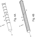
- FIGS. 4A-4B disclose embodiments of mandrels 26 for forming a first pattern.
- FIG. 4A is a perspective view of an embodiment of mandrel 26 for forming protrusions 22 in passageways 16 of a heat exchanger.
- FIG. 4B is a perspective view of an embodiment of mandrel 26 for forming grooved indentations 24 in passageways 16 of a heat exchanger.
- Protrusion mandrel 36 shown in FIG. 4A forms protrusions 22 in radially inner surface 18 of passageways 16, hereinafter referred to as protrusion mandrel 36.
- Protrusion mandrel 36 has a plurality of protrusions. Each protrusion is a circumferential protrusion from the tooling surface. Each protrusion has protrusion height 38, protrusion width 40, and protrusion spacing 42. Protrusion height 38 is how far the protrusion extends from the tooling surface of protrusion mandrel 36.
- Protrusion width 40 is an axial width of the circumferential protrusion.
- Protrusion spacing 42 is a distance between the each of the plurality of protrusions.
- Protrusion spacing 42 is therefore the width of each of the of protrusions 22.
- Protrusions 22 are discussed further above with reference to FIG. 2A .
- Protrusion mandrel 36 can be formed from graphite.
- Tread mandrel 44 has a single protrusion.
- the single protrusion extends from a tooling surface of tread mandrel 44.
- the single protrusion circumferentially wraps around the circumference of tread mandrel 44 a plurality of times.
- the single protrusion has tread height 46, tread width 48, and tread spacing 50.
- Tread height 46 is how far the protrusion extends from the tooling surface of tread mandrel 44.
- Tread width 48 is an axial width of the single protrusion.
- Tread spacing 50 is the distance between each of the plurality of circumferential wraps.
- Tread mandrel 44 can be formed from graphite.
- FIG. 5 is a cross sectional view of an embodiment of shell and tube heat exchanger 52.
- Shell and tube heat exchanger 52 includes shell 54 and tubes 55.
- Each of tubes 55 includes passageway 16 with radially inner surface 18 and radially outer part surface 20.
- Shell 54 has first and second entrances (56, 60) and first and second exits (58, 62).
- Shell 54 surrounds a plurality of tubes 55.
- a first fluid flows from first entrance 56 to first exit 58.
- the first fluid flows over radially outer part surface 20 of each of tubes 55.
- a second fluid fluids from second entrance 60 to second exit 62.
- the second fluid flows through the plurality of passageways 16 inside of tubes 55.
- Each of the plurality of passageways 16 can have a first pattern on radially inner surface 18.
- the first pattern can be protrusions 22, grooved indentations 24, or any other combination of protrusions and indentations as discussed above with respect to FIGS. 2A-2B .
- Radially outer part surface 20 can have a second pattern.
- the second pattern can be a plurality of fins, a rough surface, or any combination of protrusions, indentations, and roughened surfaces as discussed above with respect to FIG 3 .
- Shell 54 and tubes 55 can be formed from G-CMC through a manufacturing process similar to the process described above with reference to FIG. 3 .
- a method of manufacturing a heat exchanger core from glass ceramic matrix composite is described.
- the method of manufacturing a heat exchanger core from glass ceramic matrix composite of the preceding paragraph can optionally include, additionally and/or alternatively, any one or more of the following features, configurations and/or additional components: placing one or more reinforcing fibers around one or more mandrels into a mold cavity, infiltrating the one or more reinforcing fibers with a glass matrix material to produce an infiltrated core, and removing the one or more mandrels to create one or more passages passing through the infiltrated core.
- infiltrating the one or more reinforcing fibers with a glass matrix material to produce an infiltrated core includes increasing a temperature of the mold cavity to melt a reservoir of the glass matrix material, and injecting molten glass into the one or more reinforcing fibers to produce an infiltrated core.
- infiltrating the one or more reinforcing fibers with a glass matrix material to produce an infiltrated core includes placing a powered glass matrix material onto the one or more reinforcing fibers, increasing a temperature of the mold cavity to melt the powered glass matrix material, and applying a pressure to the one or more reinforcing fibers to produce an infiltrated core.
- a further embodiment of any of the foregoing methods further comprising heat treating the infiltrated core, wherein heat treating the infiltrated core converts the glass matrix material to a glass-ceramic material.
- removing the one or more mandrels includes oxidizing the one or more mandrels.
- a heat exchanger can optionally include, additionally and/or alternatively, any one or more of the following features, configurations and/or additional components: one or more tubular regions, where each tubular region of the one or more tubular regions includes a passage with a radially inner surface and a radially outer surface.
- the heat exchanger can further include one or more reinforcing fibers between the radially inner surface and the radially outer surface of each tubular region and a glass matrix material infiltrating the one or more reinforcing fibers.
- the heat exchanger can further include a first pattern formed into the radially inner surface of each tubular region and a second pattern formed into the radially outer surface of each tubular region.
- each tubular region is substantially parallel to an adjacent tubular region
- a further embodiment of any of the foregoing heat exchangers wherein a porosity of the glass matrix material of the heat exchanger is less than 5% of a total volume of the glass matrix material.
- a further embodiment of any of the foregoing heat exchangers further includes a case enclosing the one or more tubular regions and forming a second passageway between an interior surface of the case and the outer surface of each tubular region.
- a further embodiment of any of the foregoing heat exchangers, wherein the first pattern comprises a plurality of protrusions.
- a further embodiment of any of the foregoing heat exchangers, wherein the first pattern comprises a plurality of treads.
Landscapes
- Engineering & Computer Science (AREA)
- Chemical & Material Sciences (AREA)
- Materials Engineering (AREA)
- Organic Chemistry (AREA)
- Manufacturing & Machinery (AREA)
- Ceramic Engineering (AREA)
- Dispersion Chemistry (AREA)
- Mechanical Engineering (AREA)
- Thermal Sciences (AREA)
- General Engineering & Computer Science (AREA)
- Physics & Mathematics (AREA)
- Life Sciences & Earth Sciences (AREA)
- Chemical Kinetics & Catalysis (AREA)
- General Chemical & Material Sciences (AREA)
- Geochemistry & Mineralogy (AREA)
- Moulds For Moulding Plastics Or The Like (AREA)
Abstract
Description
- This disclosure relates generally to heat exchangers and more particularly to heat exchangers made from Ceramic Matrix Composite (CMC).
- Heat exchangers are made of many different types of materials. CMC heat exchangers are particularly useful in high temperature environments. However, CMC materials can have a low thermal conductivity, reducing the efficiency of CMC heat exchangers. Therefore, a method of augmenting and enhancing heat transfer in CMC heat exchangers is desired.
- In one embodiment, a method of manufacturing a heat exchanger core from glass ceramic matrix composite, wherein the method includes placing one or more reinforcing fibers around one or more mandrels into a mold cavity. A glass matrix material infiltrates the one or more reinforcing fibers to produce an infiltrated core and the one or more mandrels are removed to create one or more passages passing through the infiltrated core.
- In another embodiment, a heat exchanger includes one or more tubular regions, and each tubular region of the one or more tubular regions includes a passage with a radially inner surface and a radially outer surface. One or more reinforcing fibers is between the radially inner surface and the radially outer surface of each tubular region. A glass matrix material infiltrates the one or more reinforcing fibers. A first pattern is formed into the radially inner surface of each tubular region and a second pattern is formed into the radially outer surface of each tubular region.
-
-
FIG. 1 is a perspective view of an embodiment of a tube sheet heat exchanger. -
FIG 2A is a cross sectional view of a passageway of the tube sheet heat exchanger ofFIG. 1 along line A-A with protrusions. -
FIG 2B is a cross sectional view of a passageway of the tube sheet heat exchanger ofFIG. 1 along line A-A with grooved indentations. -
FIG. 3A is a flow diagram of the heat exchanger ofFIG. 1 being manufactured using injection molding. -
FIG. 3B is a flow diagram of the heat exchanger ofFIG. 1 being manufactured using hot pressing. -
FIG. 4A is a perspective view of a mandrel for forming protrusions in a heat exchanger. -
FIG. 4B is a perspective view of a mandrel for forming grooved indentations in a heat exchanger. -
FIG. 5 is a cross sectional view of an embodiment of a shell and tube heat exchanger. - This disclosure relates to a heat exchanger made from Ceramic Matrix Composite (CMC) materials, and in particular to heat exchangers formed of Glass Ceramic Matrix Composite (G-CMC) materials. The heat exchanger has surface features formed from G-CMC materials. The surface features can be protrusions or indentations either internally or externally which break up the flow boundary layer and increase flow turbulence, thereby increasing heat transfer in the heat exchanger. The heat exchanger will be discussed below with reference to
FIGS. 1-5 . -
FIG. 1 is a perspective view of an embodiment of tubesheet heat exchanger 10 formed from G-CMC materials. Tubesheet heat exchanger 10 comprisestubular regions 12,flat regions 14, andpassageways 16.Passageways 16 comprises radiallyinner part surface 18 and radiallyouter part surface 20. - Tube
sheet heat exchanger 10 transfers heat from a first fluid to a second fluid. The first fluid can be at a higher temperature than the second fluid or vice-versa. The first fluid flows over radiallyouter part surface 20. The second fluid flows throughpassageways 16 and contacts radiallyinner part surface 18. The first fluid flows at an angle relative to the second fluid. The angle can be between 0 and 180 degrees.Tubular regions 12 are spaced apart from one another byflat regions 14 and form raised regions betweenflat regions 14. In some embodimentsflat regions 14 are wide. In alternative embodiments,flat regions 14 are substantially narrow. Alternatively,tubular regions 12 can directly abut each other, thusflat regions 14 would substantially not be present.Tubular regions 12house passageways 16.Tubular regions 12 are the regions where heat transfer from the first fluid to the second fluid primarily occurs. When present, some heat transfer occurs inflat regions 14. -
FIGS. 2A-2B each disclose a cross-sectional view of an embodiment ofpassageways 16 of tubesheet heat exchanger 10 and will be discussed together.FIG 2A is a cross-sectional view ofpassageway 16 of tubesheet heat exchanger 10 ofFIG. 1 taken along line A-A withprotrusions 22.FIG. 2A includes radiallyinner part surface 18, radiallyouter part surface 20, andprotrusions 22.FIG 2B is a cross-sectional view ofpassageway 16 of tubesheet heat exchanger 10 ofFIG. 1 taken along line A-A, exceptpassageway 16 comprisesgrooved indentations protrusions 22.FIG. 2B includes radiallyinner part surface 18, radiallyouter part surface 20, and groovedindentations - On radially
inner part surface 18 of passageways 16 a first pattern is formed. In the embodiment ofFIG. 2A , the first pattern is formed byprotrusions 22. In the embodiment ofFIG. 2B , the first pattern is formed bygrooved indentations indentation 23 has a tight tread spacing whereasgrooved indentation 25 has a wide tread spacing. Groovedindentation 24 has a tread spacing between the tight tread spacing ofgrooved indentation 23 and the wide tread spacing ofgrooved indentation 25. In other embodiments, the first pattern can be a combination ofgrooved indentations protrusions 22 and groovedindentations same passageway 16. The first pattern can further be any combination of protrusions and/or indentations which modulate a flow of a fluid throughpassageway 16. Modulation of the flow of the fluid throughpassageway 16 increases heat transfer from radiallyinner part surface 18 into the G-CMC material with the heat then conducting to radiallyouter part surface 20. Modulation of the flow can include breaking up the flow boundary layer and/or inducing mixing and turbulence withinpassageway 16, thereby in some cases changing a substantially laminar flow to a substantially turbulent flow. Breaking up the flow boundary layer can lead to flow disruption and increased mixing. Further, if turbulent flow is induced heat transfer can occur even more readily as turbulent flow does not have an insulating layer along the radiallyinner part surface 18. -
Protrusions 22 create turbulent flow by protruding into a flow column inpassageway 16 thereby interrupting the flow along radiallyinner part surface 18.Grooved indentations passageway 16 by altering flow nearest radiallyinner part surface 18, thereby disrupting the overall flow column inpassageway 16. A tighter tread spacing can disrupt the overall flow column more than a wider tread spacing, however this further increases the pressure drop across thepassageway 16 Bothprotrusions 22 andgrooved indentations inner part surface 18, disrupting the insulation layer which forms in laminar flow. Additionally, bothprotrusions 22 andgrooved indentations outer part surface 20. -
Figures 3A and3B each disclose an embodiment of forming a G-CMC component and will be discussed together.FIG. 3A is flow diagram of G-CMC component being manufactured usingmold 32 withinjection sites 33 therein. The flow diagram ofFIG. 3A includes the steps of providingmandrel 26, formingfiber preform 28 aroundmandrel 26, injectingfiber preform 28 withglass matrix material 30, removingmandrels 26, and providing the finalized G-CMC component. The flow diagram ofFIG. 3B includes the steps of providingmandrel 26, formingfiber preform 28 aroundmandrel 26, infiltratingfiber preform 28 withglass matrix material 30, hotpressing fiber preform 28 with die set 34, removingmandrels 26, and providing the finalized G-CMC component. - As shown in
figures 3A and3B ,first step 100 in a possible embodiment of manufacturing the G-CMC component is providingmandrel 26 to a build surface. In some embodiments, the build surface can bemold 32. In the embodiments offigures 3A and3B ,mandrel 26 is formed of graphite. In alternative embodiments,mandrel 26 can be formed of any material know to those of skill in the art to be chemically inert withchosen substate 30.Mandrel 26 can have the first pattern discussed above with reference toFIGS. 2A and 2B formed in negative on an outer tooling surface ofmandrel 26. The first pattern can include tooling surface protrusions or indentations which will form part surface indentations or protrusions, respectively, on radiallyinner part surface 18 ofpassageways 16. - As shown in
figures 3A and3B ,second step 102 of manufacturing the G-CMC component is formingfiber preform 28 aroundmandrel 26.Fiber preform 28 provides a surface forglass matrix material 30 to adhere too.Fiber preform 28 also provides reinforcement and improves mechanical properties of the G-CMC component. Specifically,fiber preform 28 can increase a tensile strength of the G-CMC component and increase a heat transfer coefficient of the G-CMC component from radiallyinner part surface 18 to radiallyouter part surface 20. In the embodiment offigures 3A and3B ,fiber preform 28 is formed of one or more ceramic fibers formed around the mandrel. In alternativeembodiments fiber preform 28 can be formed of any fibers which are crystalline and compatible with toglass matrix material 30. In alternative embodiments,fiber preform 28 can be silicon carbide, carbon, oxides, or combinations thereof. In alternativeembodiments fiber preform 28 can be oriented in circumferential directions, linear directions, or random directions. In alternativeembodiments fiber preform 28 can be formed from a plurality of chopped fibers. In alternativeembodiments fiber preform 28 can be a single continuous thread wrapped and woven into layers. - As shown in
figures 3A and3B ,third step 104 of the embodiment offigures 3A and3B of manufacturing the G-CMC component is positioningmandrels 26 withfiber preform 28 thereon next to each other on the build surface, if there is more than one mandrel.Additional fiber preform 28 can be positioned betweenmandrels 26 to connectmandrels 26 together. As shown inFIG 3B .glass matrix material 30 is then distributed infiber preforms 28. - In the embodiment of
FIG. 3B glass matrix material 30 is glass. In alternative embodiments,glass matrix material 30 can be any material which hardens when cooled and which does not destroyfiber preform 28 andmandrels 26. In alternative embodiments,glass matrix material 30 can include pure glass, silicone carbide, molten silicon, and combinations thereof. When hardenedglass matrix material 30 andfiber preform 28 have a porosity of less than 10%, less than 5%, less than 3%, or less than 1%. Due to the low porosity, a distance between radiallyinner part surface 18 and radiallyouter part surface 20 can be reduced which improves heat transfer characteristics. Further, since the porosity is lower, increased control over surface roughness is possible. Specifically, surface roughness control with resolutions of less than 0.3mm, less than 0.1mm, and less than 0.03mm are possible. - As shown in
figure 3A ,injection step 105 of the embodiment offigure 3A of manufacturing the G-CMC component is injecting moltenglass matrix material 30 intomold 32 throughinjection sites 33. Moltenglass matrix material 30 infiltrates the spaces betweenfiber preform 28, thereby forming an infiltrated core of the G-CMC component. Before injecting moltenglass matrix material 30, a pressure is applied tocompact fiber preform 28. Compactingfiber preform 28 reduces the space between fibers offiber preform 28 thereby decreasing a porosity of the G-CMC component. A temperature ofmold 32 is also increased. Increasing the temperature ofmold 32 allows forglass matrix material 30 to flow more readily, thereby further decreasing a porosity of the G-CMC component. After thefiber preform 28 has been compacted andmold 32 has been heated, moltenglass matrix material 30 is then injected intomold 32 throughinjection sites 33.Injection sites 33 can be one-way valves to increase a pressure of the injected moltenglass matrix material 30. Whenglass matrix material 30 hardens,glass matrix material 30 andfiber preform 28 will take the shape ofmold 32.Mold 32 can be flat.Mold 32 can be textured. The texture onmold 32 can comprise protrusions or indentations. The plurality of protrusions can comprise a plurality of fins (not shown). The plurality of fins increases a surface area which interacts with the first fluid, breaks up the flow boundary, and/or induces turbulence in a flow of the first fluid.Mold 32 can be formed from graphite or any other material that does not destroyglass matrix material 30 and capable of handling the high temperatures ofglass matrix material 30. - In the embodiment of
FIG. 3A glass matrix material 30 is glass. In alternative embodiments,glass matrix material 30 can be any material which hardens when cooled and which does not destroyfiber preform 28 andmandrels 26. In alternative embodiments,glass matrix material 30 can include pure glass, silicone carbide, molten silicon, and combinations thereof. When hardenedglass matrix material 30 andfiber preform 28 have a porosity of less than 10%, less than 5%, less than 3%, or less than 1%. Due to the low porosity, a distance between radiallyinner part surface 18 and radiallyouter part surface 20 can be reduced which improves heat transfer characteristics. Further, since the porosity is lower, increased control over surface roughness is possible. Specifically, surface roughness control with resolutions of less than 0.3 mm, less than 0.1 mm, and less than 0.03 mm are possible. - As shown in
figure 3B , pressingstep 106 of the embodiment offigure 3B of manufacturing the G-CMC component comprises hot pressing infiltratedfiber preform 28 with die set 34. Prior to hotpressing fiber preform 28, a powdered version ofglass matrix material 30 must be placed ontofiber preform 28. Once the powdered version ofglass matrix material 30 is placed onto fiber preform 28 a temperature is increased which melts the powdered version ofglass matrix material 30. After theglass matrix material 30 has been melted, then a pressure can be applied by die set 34, thereby hot-pressingfiber preform 28. The melting and applied pressure removes small bubbles inglass matrix material 30 between fibers offiber preform 28 thereby decreasing a porosity of the G-CMC component. - Die set 34 can have a second pattern formed into contact surfaces of die set 34. As shown in
figure 3B , the second pattern can havetubular form 12F andflat form 14F. The second pattern as shown infigure 3B decreases a thickness between radiallyinner part surface 18 ofpassageway 16 and radiallyouter part surface 20, increasing heat transfer. The second pattern also formstubular portions 12 andflat portions 14 inouter part surface 20. The second pattern can further include a textured surface. The textured surface can include protrusions or indentations. The protrusions can include a plurality of fins (not shown) which protrude fromtubular region 12 andflat region 14. The plurality of fins increases a surface area which interacts with the first fluid, breaks up the flow boundary, and/or induces turbulence in a flow of the first fluid. The textured surface can alternatively or in addition include a roughened surface. The roughened surface has a finer length scale than the textured surface. The roughened surface can be uniform. The roughened surface of radiallyouter part surface 20 has an RMS surface roughness of at least 3x, of least 5x, of at least 10X, or at least 20x of the surface prior to hot pressing with die set 34. A possible embodiment comprises a surface which can be considered nominally smooth with .001" deviations, therefore a roughened surface after hot pressing with deviations of up to 0.020" may have a surface roughness of 20X the surface prior to hot pressing. Protrusions 22 andgrooved indentations mold 32. Specifically, a height ofprotrusions 22 andgrooved indentations mold 32 have a height of up to 0.05" (1.27mm), up to 0.01" (0.254mm), and up to 0.020" (0.508mm). - Die set 34 can be manufactured with additive manufacturing. Die set 34 can also be formed from graphite. Not shown in
figure 3B , a chemical vapor deposition process can be applied toouter part surface 20 after hot pressing with die set 34. The chemical vapor deposition process can increase a roughness ofouter part surface 20. - Reinforcement particles can be hot pressed into
glass matrix material 30 andfiber preform 28 as part offourth step 106. The reinforcement particles can include local additions of secondary fibers, particulates, nanotubes, and a combination thereof. When secondary fibers are used, the secondary fibers can be at the same or different orientation asfiber preform 28. The secondary fibers can be the same or a different material thanfiber preform 28. These reinforcement particles can improve the material characteristics of tubesheet heat exchanger 10 in the areas where the reinforcement particles are applied. The material characteristics which are increased include strength, stiffness, and thermal transfer characteristics. Die set 34 can be manufactured with additive manufacturing. Die set 34 can be formed from graphite. - Although
injection step 105 andpressing step 106 are discussed here in separate figures,figures 3A and3B respectively,injection step 105 andpressing step 106 can be used on the same G-CMC component. Specifically, a component can be formed viainjection step 105 and a surface pattern can be imparted withpressing step 106. Prior tofifth step 108,glass matrix material 30 andfiber preform 28 can be heat treated. Heat treatingglass matrix material 30 andfiber preform 28 can crystalizeglass matrix material 30. Crystalizingglass matrix material 30 can convertglass matrix material 30 to a ceramic and/or glass-ceramic material. Crystalizingglass matrix material 30 can increase a hardness ofglass matrix material 30. Crystalizingglass matrix material 30 can also decrease a porosity of theglass matrix material 30 further. - As shown in
figures 3A and3B ,fifth step 108 in the embodiment offigures 3A and3B is removingmandrels 26.Mandrels 26 can be removed via chemical or mechanical means. Chemical removal can include oxidization. Whenmandrels 26 are formed of graphite,mandrels 26 can be oxidized away via a burning process. Mechanical removal ofmandrels 26 can include sonication, electrical discharge machining, or a combination thereof.Mandrels 26 can be removed by any other method known to those of skill in the art of removing a sacrificial component from within another component. - As shown in
figures 3A and3B , after completion offifth step 108, manufacturing of the G-CMC component is completed, as represented byreference 110. Withcompletion 110 of the G-CMC component, the G-CMC component is ready for installation into any larger assembly. Specifically, any larger assembly where heat must be transferred from a first fluid to a second fluid. - The above steps 100-110 were described with reference to a G-CMC component. Steps 100-110 can likewise be utilized when forming tube
sheet heat exchanger 10. Steps 100-110 can further be utilized when forming shell and tube heat exchanger 52 (discussed below with reference toFIG. 5 ) or any other heat exchanger with a first and a second passageway. The steps 100-110 can further be used for any other G-CMC components. The method described above with reference to steps 100-110 can be particularly useful for any G-CMC component which experiences high temperatures. -
FIGS. 4A-4B disclose embodiments ofmandrels 26 for forming a first pattern.FIG. 4A is a perspective view of an embodiment ofmandrel 26 for formingprotrusions 22 inpassageways 16 of a heat exchanger.FIG. 4B is a perspective view of an embodiment ofmandrel 26 for forminggrooved indentations 24 inpassageways 16 of a heat exchanger. -
Mandrel 26 shown inFIG. 4A formsprotrusions 22 in radiallyinner surface 18 ofpassageways 16, hereinafter referred to asprotrusion mandrel 36.Protrusion mandrel 36 has a plurality of protrusions. Each protrusion is a circumferential protrusion from the tooling surface. Each protrusion hasprotrusion height 38,protrusion width 40, andprotrusion spacing 42.Protrusion height 38 is how far the protrusion extends from the tooling surface ofprotrusion mandrel 36.Protrusion width 40 is an axial width of the circumferential protrusion.Protrusion spacing 42 is a distance between the each of the plurality of protrusions. Each of these distances can be varied for each and between each of the plurality of protrusions. Whenprotrusion mandrel 36 is used in the formation ofprotrusions 22,glass matrix material 30 infills between each of the plurality of protrusions.Protrusion spacing 42 is therefore the width of each of the ofprotrusions 22.Protrusions 22 are discussed further above with reference toFIG. 2A .Protrusion mandrel 36 can be formed from graphite. -
Mandrel 26 shown inFIG. 4B forms groovedindentations 24 in radiallyinner surface 18 ofpassageways 16, hereinafter referred to astread mandrel 44. Treadmandrel 44 has a single protrusion. The single protrusion extends from a tooling surface oftread mandrel 44. The single protrusion circumferentially wraps around the circumference of tread mandrel 44 a plurality of times. The single protrusion hastread height 46,tread width 48, and treadspacing 50. Treadheight 46 is how far the protrusion extends from the tooling surface oftread mandrel 44.Tread width 48 is an axial width of the single protrusion. Tread spacing 50 is the distance between each of the plurality of circumferential wraps. Whentread mandrel 44 is used in the formation of groovedindentations 24,glass matrix material 30 infills between each of the plurality of circumferential wraps and each of the plurality of circumferential wraps presses into the radiallyinner surface 18 ofpassageway 16 forming groovedindentations 24. A width of groovedindentations 24 is the width oftread width 48 and a depth of groovedindentations 24 istread height 46.Grooved indentations 24 are discussed further above with reference toFIG. 2B . Treadmandrel 44 can be formed from graphite. -
FIG. 5 is a cross sectional view of an embodiment of shell andtube heat exchanger 52. Shell andtube heat exchanger 52 includesshell 54 andtubes 55. Each oftubes 55 includespassageway 16 with radiallyinner surface 18 and radiallyouter part surface 20.Shell 54 has first and second entrances (56, 60) and first and second exits (58, 62). -
Shell 54 surrounds a plurality oftubes 55. A first fluid flows fromfirst entrance 56 tofirst exit 58. The first fluid flows over radiallyouter part surface 20 of each oftubes 55. A second fluid fluids fromsecond entrance 60 tosecond exit 62. The second fluid flows through the plurality ofpassageways 16 inside oftubes 55. Each of the plurality ofpassageways 16 can have a first pattern on radiallyinner surface 18. The first pattern can beprotrusions 22, groovedindentations 24, or any other combination of protrusions and indentations as discussed above with respect toFIGS. 2A-2B . Radiallyouter part surface 20 can have a second pattern. The second pattern can be a plurality of fins, a rough surface, or any combination of protrusions, indentations, and roughened surfaces as discussed above with respect toFIG 3 .Shell 54 andtubes 55 can be formed from G-CMC through a manufacturing process similar to the process described above with reference toFIG. 3 . - The following are non-exclusive descriptions of possible embodiments of the present invention.
- A method of manufacturing a heat exchanger core from glass ceramic matrix composite.
- The method of manufacturing a heat exchanger core from glass ceramic matrix composite of the preceding paragraph can optionally include, additionally and/or alternatively, any one or more of the following features, configurations and/or additional components: placing one or more reinforcing fibers around one or more mandrels into a mold cavity, infiltrating the one or more reinforcing fibers with a glass matrix material to produce an infiltrated core, and removing the one or more mandrels to create one or more passages passing through the infiltrated core.
- A further embodiment of the foregoing method, wherein infiltrating the one or more reinforcing fibers with a glass matrix material to produce an infiltrated core includes increasing a temperature of the mold cavity to melt a reservoir of the glass matrix material, and injecting molten glass into the one or more reinforcing fibers to produce an infiltrated core.
- A further embodiment of any of the foregoing methods, wherein infiltrating the one or more reinforcing fibers with a glass matrix material to produce an infiltrated core includes placing a powered glass matrix material onto the one or more reinforcing fibers, increasing a temperature of the mold cavity to melt the powered glass matrix material, and applying a pressure to the one or more reinforcing fibers to produce an infiltrated core.
- A further embodiment of any of the foregoing methods, further comprising heat treating the infiltrated core, wherein heat treating the infiltrated core converts the glass matrix material to a glass-ceramic material.
- A further embodiment of any of the foregoing methods, wherein the one or more reinforcing fibers are ceramic fibers.
- A further embodiment of any of the foregoing methods, wherein the one or more mandrels are formed of graphite.
- A further embodiment of any of the foregoing methods, wherein the one or more mandrels have one or more protrusions which form a surface texture, and the surface texture forms a patterned feature on an interior surface of the infiltrated core.
- A further embodiment of any of the foregoing methods, wherein the one or more mandrels have one or more grooves which form a surface texture, and the surface texture forms a patterned feature on an interior surface of the infiltrated core.
- A further embodiment of any of the foregoing methods, wherein the mold cavity has a surface texture, and the surface texture forms a patterned feature on an exterior surface of the heat exchanger core.
- A further embodiment of any of the foregoing methods, wherein a porosity of the glass matrix material of the heat exchanger core is less than 5%.
- A further embodiment of any of the foregoing methods, wherein removing the one or more mandrels includes oxidizing the one or more mandrels.
- A heat exchanger can optionally include, additionally and/or alternatively, any one or more of the following features, configurations and/or additional components: one or more tubular regions, where each tubular region of the one or more tubular regions includes a passage with a radially inner surface and a radially outer surface. The heat exchanger can further include one or more reinforcing fibers between the radially inner surface and the radially outer surface of each tubular region and a glass matrix material infiltrating the one or more reinforcing fibers. The heat exchanger can further include a first pattern formed into the radially inner surface of each tubular region and a second pattern formed into the radially outer surface of each tubular region.
- A further embodiment of the foregoing heat exchanger, wherein each tubular region is substantially parallel to an adjacent tubular region
- A further embodiment of any of the foregoing heat exchangers, wherein a porosity of the glass matrix material of the heat exchanger is less than 5% of a total volume of the glass matrix material.
- A further embodiment of any of the foregoing heat exchangers, further includes a case enclosing the one or more tubular regions and forming a second passageway between an interior surface of the case and the outer surface of each tubular region.
- A further embodiment of any of the foregoing heat exchangers, wherein the first pattern comprises a plurality of protrusions.
A further embodiment of any of the foregoing heat exchangers, wherein the first pattern comprises a plurality of treads. - A further embodiment of any of the foregoing heat exchangers, wherein the first pattern comprises a textured surface.
- A further embodiment of any of the foregoing heat exchangers, wherein the second pattern comprises a plurality of fins.
- A further embodiment of any of the foregoing heat exchangers, wherein the second pattern comprises a textured surface.
- While the invention has been described with reference to an exemplary embodiment(s), it will be understood by those skilled in the art that various changes may be made without departing from the scope of the invention as defined by the claims. In addition, many modifications may be made to adapt a particular situation or material to the teachings of the invention without departing from the scope of the claims. Therefore, it is intended that the invention not be limited to the particular embodiment(s) disclosed, but that the invention will include all embodiments falling within the scope of the appended claims.
Claims (15)
- A method of manufacturing a heat exchanger core from glass ceramic matrix composite, wherein the method comprises:placing one or more reinforcing fibers around one or more mandrels (26) into a mold cavity;infiltrating the one or more reinforcing fibers with a glass matrix material to produce an infiltrated core; andremoving the one or more mandrels to create one or more passages passing through the infiltrated core.
- The method of claim 1, wherein infiltrating the one or more reinforcing fibers with a glass matrix material to produce an infiltrated core comprises:increasing a temperature of the mold cavity to melt a reservoir of the glass matrix material; andinjecting molten glass into the one or more reinforcing fibers to produce an infiltrated core.
- The method of claim 1, wherein infiltrating the one or more reinforcing fibers with a glass matrix material to produce an infiltrated core comprises:placing a powered glass matrix material onto the one or more reinforcing fibers;increasing a temperature of the mold cavity to melt the powered glass matrix material;applying a pressure to the one or more reinforcing fibers to produce an infiltrated core.
- The method of any preceding claim, further comprising heat treating the infiltrated core, wherein heat treating the infiltrated core converts the glass matrix material to a glass-ceramic material.
- The method of any preceding claim, wherein the one or more reinforcing fibers are ceramic fibers, and/or wherein the one or more mandrels are formed of graphite.
- The method of any preceding claim, wherein:the one or more mandrels have one or more protrusions (22) which form a surface texture; andthe surface texture forms a patterned feature on an interior surface of the infiltrated core; orthe one or more mandrels have one or more grooves (23, 24, 25) which form a surface texture; andthe surface texture forms a patterned feature on an interior surface of the infiltrated core.
- The method of any preceding claim, wherein the mold cavity has a surface texture, and the surface texture forms a patterned feature on an exterior surface of the heat exchanger core.
- The method of any preceding claim, wherein a porosity of the glass matrix material of the heat exchanger core is less than 5%.
- The method of any preceding claim, wherein removing the one or more mandrels comprises:
oxidizing the one or more mandrels. - A heat exchanger comprising:one or more tubular regions, wherein each tubular region of the one or more tubular regions comprises:a passage (16) with a radially inner surface (18); anda radially outer surface (18);one or more reinforcing fibers between the radially inner surface and the radially outer surface of each tubular region;a glass matrix material infiltrating the one or more reinforcing fibers;a first pattern formed into the radially inner surface of each tubular region; anda second pattern formed into the radially outer surface of each tubular region.
- The heat exchanger of claim 10, wherein each tubular region is substantially parallel to an adjacent tubular region.
- The heat exchanger of claim 10 or 11, wherein a porosity of the glass matrix material of the heat exchanger is less than 5% of a total volume of the glass matrix material.
- The heat exchanger of claim 10, 11 or 12, further comprising:
a case enclosing the one or more tubular regions and forming a second passageway between an interior surface of the case and the outer surface of each tubular region. - The heat exchanger of any of claims 10 to 13, wherein the first pattern comprises a plurality of protrusions, or wherein the first pattern comprises a plurality of treads, or wherein the first pattern comprises a textured surface.
- The heat exchanger of any of claims 10 to 14, wherein the second pattern comprises a plurality of fins, or wherein the second pattern comprises a textured surface.
Applications Claiming Priority (1)
| Application Number | Priority Date | Filing Date | Title |
|---|---|---|---|
| US17/825,690 US12292242B2 (en) | 2022-05-26 | 2022-05-26 | Surface texture enhanced glass-ceramic matrix composite heat exchanger |
Publications (2)
| Publication Number | Publication Date |
|---|---|
| EP4282836A1 true EP4282836A1 (en) | 2023-11-29 |
| EP4282836B1 EP4282836B1 (en) | 2025-02-12 |
Family
ID=86226837
Family Applications (1)
| Application Number | Title | Priority Date | Filing Date |
|---|---|---|---|
| EP23170171.5A Active EP4282836B1 (en) | 2022-05-26 | 2023-04-26 | Surface texture enhanced glass-ceramic matrix composite heat exchanger |
Country Status (2)
| Country | Link |
|---|---|
| US (1) | US12292242B2 (en) |
| EP (1) | EP4282836B1 (en) |
Citations (3)
| Publication number | Priority date | Publication date | Assignee | Title |
|---|---|---|---|---|
| US4428763A (en) * | 1982-05-25 | 1984-01-31 | United Technologies Corporation | Transfer molding method of producing fiber reinforced glass matrix composite articles |
| US20120125585A1 (en) * | 2007-03-08 | 2012-05-24 | Siemens Power Generation, Inc. | Cmc wall structure with integral cooling channels |
| US20210339515A1 (en) * | 2020-05-02 | 2021-11-04 | Hamilton Sundstrand Corporation | Ceramic matrix composite laminate tube sheet and method for making the same |
Family Cites Families (13)
| Publication number | Priority date | Publication date | Assignee | Title |
|---|---|---|---|---|
| US6627019B2 (en) | 2000-12-18 | 2003-09-30 | David C. Jarmon | Process for making ceramic matrix composite parts with cooling channels |
| US6651732B2 (en) * | 2001-08-31 | 2003-11-25 | Cool Shield, Inc. | Thermally conductive elastomeric heat dissipation assembly with snap-in heat transfer conduit |
| WO2007124409A2 (en) | 2006-04-20 | 2007-11-01 | Velocys, Inc. | Process for treating and/or forming a non-newtonian fluid using microchannel process technology |
| US7452189B2 (en) | 2006-05-03 | 2008-11-18 | United Technologies Corporation | Ceramic matrix composite turbine engine vane |
| US20090004425A1 (en) | 2007-06-28 | 2009-01-01 | The Boeing Company | Ceramic Matrix Composite Structure having Fluted Core and Method for Making the Same |
| DE102009007446B4 (en) | 2009-02-04 | 2012-03-29 | Wieland-Werke Ag | Heat exchanger tube and method for its production |
| US8545938B2 (en) | 2011-10-03 | 2013-10-01 | United Technologies Corporation | Method of fabricating a ceramic component |
| US8900661B2 (en) | 2011-10-03 | 2014-12-02 | United Technologies Corporation | Method of filling porosity of ceramic component |
| WO2016019303A1 (en) * | 2014-07-31 | 2016-02-04 | Carrier Corporation | Coated heat exchanger |
| DE102019201527A1 (en) * | 2019-02-06 | 2020-08-06 | Marion Bieler | Core element for sandwich elements and use of such a core element |
| US11656036B2 (en) * | 2019-03-14 | 2023-05-23 | Carrier Corporation | Heat exchanger and associated tube sheet |
| US11633789B2 (en) | 2020-02-10 | 2023-04-25 | Ut-Battelle, Llc | Compliant heat exchangers, heat pipes and methods for making same |
| US12024458B2 (en) | 2020-09-04 | 2024-07-02 | Hamilton Sundstrand Corporation | Glass-ceramic matrix composite feedstock and forming |
-
2022
- 2022-05-26 US US17/825,690 patent/US12292242B2/en active Active
-
2023
- 2023-04-26 EP EP23170171.5A patent/EP4282836B1/en active Active
Patent Citations (3)
| Publication number | Priority date | Publication date | Assignee | Title |
|---|---|---|---|---|
| US4428763A (en) * | 1982-05-25 | 1984-01-31 | United Technologies Corporation | Transfer molding method of producing fiber reinforced glass matrix composite articles |
| US20120125585A1 (en) * | 2007-03-08 | 2012-05-24 | Siemens Power Generation, Inc. | Cmc wall structure with integral cooling channels |
| US20210339515A1 (en) * | 2020-05-02 | 2021-11-04 | Hamilton Sundstrand Corporation | Ceramic matrix composite laminate tube sheet and method for making the same |
Also Published As
| Publication number | Publication date |
|---|---|
| EP4282836B1 (en) | 2025-02-12 |
| US12292242B2 (en) | 2025-05-06 |
| US20230384044A1 (en) | 2023-11-30 |
Similar Documents
| Publication | Publication Date | Title |
|---|---|---|
| US20130306686A1 (en) | Hot Runner Nozzle | |
| US8353392B2 (en) | Internally vented brake disk with improved heat dissipation | |
| CN109869237B (en) | Cylinder liner assembly and method of manufacturing a cylinder liner assembly | |
| US11633789B2 (en) | Compliant heat exchangers, heat pipes and methods for making same | |
| US20080142196A1 (en) | Heat Pipe with Advanced Capillary Structure | |
| KR940009338B1 (en) | Production of base material having perforated surface | |
| JP2005147654A (en) | Method of manufacturing ceramic glow plug | |
| CN101449103B (en) | Multi-layer heating element | |
| EP4282836B1 (en) | Surface texture enhanced glass-ceramic matrix composite heat exchanger | |
| EP1724090B1 (en) | Injection nozzle with a thermal shroud and method of making the same | |
| CN104871412B (en) | Induction rotor assembly and method of casting the same | |
| CN104874679A (en) | System and process for producing a metallic article | |
| CN100584574C (en) | Heated nozzle unit for moulding plastics material | |
| JP3832515B2 (en) | Honeycomb structure extrusion method | |
| CN115945587A (en) | A mold for reducing the circumference of the section of the tube blank and a method for processing the tube blank | |
| US10182471B2 (en) | Electric heater crushable cores and compacted unitary heater device and method of making such devices | |
| US20230219297A1 (en) | Heat-transfer devices and methods of forming the heat-transfer devices | |
| JP2921195B2 (en) | Method for producing carrier for catalytic converter | |
| JP7165361B2 (en) | heatsink | |
| US11304266B2 (en) | Electric heater crushable cores and compacted unitary heater devices and method for making such devices | |
| JP4475427B2 (en) | Plunger sleeve and manufacturing method thereof | |
| JP6355615B2 (en) | Manufacturing method of ceramic sintered body | |
| US20060145397A1 (en) | Method and tool for molding | |
| EP4647255A1 (en) | Cores for ceramic matrix composite components | |
| JP2010244786A (en) | Seeds heater and heating method using the same |
Legal Events
| Date | Code | Title | Description |
|---|---|---|---|
| PUAI | Public reference made under article 153(3) epc to a published international application that has entered the european phase |
Free format text: ORIGINAL CODE: 0009012 |
|
| STAA | Information on the status of an ep patent application or granted ep patent |
Free format text: STATUS: THE APPLICATION HAS BEEN PUBLISHED |
|
| AK | Designated contracting states |
Kind code of ref document: A1 Designated state(s): AL AT BE BG CH CY CZ DE DK EE ES FI FR GB GR HR HU IE IS IT LI LT LU LV MC ME MK MT NL NO PL PT RO RS SE SI SK SM TR |
|
| STAA | Information on the status of an ep patent application or granted ep patent |
Free format text: STATUS: REQUEST FOR EXAMINATION WAS MADE |
|
| 17P | Request for examination filed |
Effective date: 20240529 |
|
| RBV | Designated contracting states (corrected) |
Designated state(s): AL AT BE BG CH CY CZ DE DK EE ES FI FR GB GR HR HU IE IS IT LI LT LU LV MC ME MK MT NL NO PL PT RO RS SE SI SK SM TR |
|
| GRAP | Despatch of communication of intention to grant a patent |
Free format text: ORIGINAL CODE: EPIDOSNIGR1 |
|
| STAA | Information on the status of an ep patent application or granted ep patent |
Free format text: STATUS: GRANT OF PATENT IS INTENDED |
|
| RIC1 | Information provided on ipc code assigned before grant |
Ipc: B32B 5/00 20060101ALI20240619BHEP Ipc: F28F 21/04 20060101ALI20240619BHEP Ipc: C03B 19/02 20060101AFI20240619BHEP |
|
| INTG | Intention to grant announced |
Effective date: 20240711 |
|
| GRAS | Grant fee paid |
Free format text: ORIGINAL CODE: EPIDOSNIGR3 |
|
| GRAA | (expected) grant |
Free format text: ORIGINAL CODE: 0009210 |
|
| STAA | Information on the status of an ep patent application or granted ep patent |
Free format text: STATUS: THE PATENT HAS BEEN GRANTED |
|
| AK | Designated contracting states |
Kind code of ref document: B1 Designated state(s): AL AT BE BG CH CY CZ DE DK EE ES FI FR GB GR HR HU IE IS IT LI LT LU LV MC ME MK MT NL NO PL PT RO RS SE SI SK SM TR |
|
| REG | Reference to a national code |
Ref country code: GB Ref legal event code: FG4D |
|
| REG | Reference to a national code |
Ref country code: CH Ref legal event code: EP |
|
| REG | Reference to a national code |
Ref country code: DE Ref legal event code: R096 Ref document number: 602023001972 Country of ref document: DE |
|
| REG | Reference to a national code |
Ref country code: IE Ref legal event code: FG4D |
|
| PGFP | Annual fee paid to national office [announced via postgrant information from national office to epo] |
Ref country code: FR Payment date: 20250319 Year of fee payment: 3 |
|
| REG | Reference to a national code |
Ref country code: NL Ref legal event code: MP Effective date: 20250212 |
|
| PG25 | Lapsed in a contracting state [announced via postgrant information from national office to epo] |
Ref country code: RS Free format text: LAPSE BECAUSE OF FAILURE TO SUBMIT A TRANSLATION OF THE DESCRIPTION OR TO PAY THE FEE WITHIN THE PRESCRIBED TIME-LIMIT Effective date: 20250512 |
|
| PG25 | Lapsed in a contracting state [announced via postgrant information from national office to epo] |
Ref country code: FI Free format text: LAPSE BECAUSE OF FAILURE TO SUBMIT A TRANSLATION OF THE DESCRIPTION OR TO PAY THE FEE WITHIN THE PRESCRIBED TIME-LIMIT Effective date: 20250212 |
|
| PG25 | Lapsed in a contracting state [announced via postgrant information from national office to epo] |
Ref country code: PL Free format text: LAPSE BECAUSE OF FAILURE TO SUBMIT A TRANSLATION OF THE DESCRIPTION OR TO PAY THE FEE WITHIN THE PRESCRIBED TIME-LIMIT Effective date: 20250212 |
|
| PGFP | Annual fee paid to national office [announced via postgrant information from national office to epo] |
Ref country code: DE Payment date: 20250319 Year of fee payment: 3 |
|
| PG25 | Lapsed in a contracting state [announced via postgrant information from national office to epo] |
Ref country code: ES Free format text: LAPSE BECAUSE OF FAILURE TO SUBMIT A TRANSLATION OF THE DESCRIPTION OR TO PAY THE FEE WITHIN THE PRESCRIBED TIME-LIMIT Effective date: 20250212 |
|
| REG | Reference to a national code |
Ref country code: LT Ref legal event code: MG9D |
|
| PG25 | Lapsed in a contracting state [announced via postgrant information from national office to epo] |
Ref country code: IS Free format text: LAPSE BECAUSE OF FAILURE TO SUBMIT A TRANSLATION OF THE DESCRIPTION OR TO PAY THE FEE WITHIN THE PRESCRIBED TIME-LIMIT Effective date: 20250612 Ref country code: NO Free format text: LAPSE BECAUSE OF FAILURE TO SUBMIT A TRANSLATION OF THE DESCRIPTION OR TO PAY THE FEE WITHIN THE PRESCRIBED TIME-LIMIT Effective date: 20250512 |
|
| PG25 | Lapsed in a contracting state [announced via postgrant information from national office to epo] |
Ref country code: NL Free format text: LAPSE BECAUSE OF FAILURE TO SUBMIT A TRANSLATION OF THE DESCRIPTION OR TO PAY THE FEE WITHIN THE PRESCRIBED TIME-LIMIT Effective date: 20250212 |
|
| PG25 | Lapsed in a contracting state [announced via postgrant information from national office to epo] |
Ref country code: HR Free format text: LAPSE BECAUSE OF FAILURE TO SUBMIT A TRANSLATION OF THE DESCRIPTION OR TO PAY THE FEE WITHIN THE PRESCRIBED TIME-LIMIT Effective date: 20250212 |
|
| PG25 | Lapsed in a contracting state [announced via postgrant information from national office to epo] |
Ref country code: PT Free format text: LAPSE BECAUSE OF FAILURE TO SUBMIT A TRANSLATION OF THE DESCRIPTION OR TO PAY THE FEE WITHIN THE PRESCRIBED TIME-LIMIT Effective date: 20250612 Ref country code: LV Free format text: LAPSE BECAUSE OF FAILURE TO SUBMIT A TRANSLATION OF THE DESCRIPTION OR TO PAY THE FEE WITHIN THE PRESCRIBED TIME-LIMIT Effective date: 20250212 |
|
| PG25 | Lapsed in a contracting state [announced via postgrant information from national office to epo] |
Ref country code: GR Free format text: LAPSE BECAUSE OF FAILURE TO SUBMIT A TRANSLATION OF THE DESCRIPTION OR TO PAY THE FEE WITHIN THE PRESCRIBED TIME-LIMIT Effective date: 20250513 Ref country code: BG Free format text: LAPSE BECAUSE OF FAILURE TO SUBMIT A TRANSLATION OF THE DESCRIPTION OR TO PAY THE FEE WITHIN THE PRESCRIBED TIME-LIMIT Effective date: 20250212 |
|
| REG | Reference to a national code |
Ref country code: AT Ref legal event code: MK05 Ref document number: 1765937 Country of ref document: AT Kind code of ref document: T Effective date: 20250212 |
|
| PG25 | Lapsed in a contracting state [announced via postgrant information from national office to epo] |
Ref country code: SE Free format text: LAPSE BECAUSE OF FAILURE TO SUBMIT A TRANSLATION OF THE DESCRIPTION OR TO PAY THE FEE WITHIN THE PRESCRIBED TIME-LIMIT Effective date: 20250212 |
|
| PG25 | Lapsed in a contracting state [announced via postgrant information from national office to epo] |
Ref country code: SM Free format text: LAPSE BECAUSE OF FAILURE TO SUBMIT A TRANSLATION OF THE DESCRIPTION OR TO PAY THE FEE WITHIN THE PRESCRIBED TIME-LIMIT Effective date: 20250212 |
|
| PG25 | Lapsed in a contracting state [announced via postgrant information from national office to epo] |
Ref country code: DK Free format text: LAPSE BECAUSE OF FAILURE TO SUBMIT A TRANSLATION OF THE DESCRIPTION OR TO PAY THE FEE WITHIN THE PRESCRIBED TIME-LIMIT Effective date: 20250212 |
|
| PG25 | Lapsed in a contracting state [announced via postgrant information from national office to epo] |
Ref country code: IT Free format text: LAPSE BECAUSE OF FAILURE TO SUBMIT A TRANSLATION OF THE DESCRIPTION OR TO PAY THE FEE WITHIN THE PRESCRIBED TIME-LIMIT Effective date: 20250212 |
|
| PG25 | Lapsed in a contracting state [announced via postgrant information from national office to epo] |
Ref country code: AT Free format text: LAPSE BECAUSE OF FAILURE TO SUBMIT A TRANSLATION OF THE DESCRIPTION OR TO PAY THE FEE WITHIN THE PRESCRIBED TIME-LIMIT Effective date: 20250212 |
|
| PG25 | Lapsed in a contracting state [announced via postgrant information from national office to epo] |
Ref country code: CZ Free format text: LAPSE BECAUSE OF FAILURE TO SUBMIT A TRANSLATION OF THE DESCRIPTION OR TO PAY THE FEE WITHIN THE PRESCRIBED TIME-LIMIT Effective date: 20250212 Ref country code: EE Free format text: LAPSE BECAUSE OF FAILURE TO SUBMIT A TRANSLATION OF THE DESCRIPTION OR TO PAY THE FEE WITHIN THE PRESCRIBED TIME-LIMIT Effective date: 20250212 |
|
| PG25 | Lapsed in a contracting state [announced via postgrant information from national office to epo] |
Ref country code: RO Free format text: LAPSE BECAUSE OF FAILURE TO SUBMIT A TRANSLATION OF THE DESCRIPTION OR TO PAY THE FEE WITHIN THE PRESCRIBED TIME-LIMIT Effective date: 20250212 |
|
| PG25 | Lapsed in a contracting state [announced via postgrant information from national office to epo] |
Ref country code: SK Free format text: LAPSE BECAUSE OF FAILURE TO SUBMIT A TRANSLATION OF THE DESCRIPTION OR TO PAY THE FEE WITHIN THE PRESCRIBED TIME-LIMIT Effective date: 20250212 |
|
| REG | Reference to a national code |
Ref country code: DE Ref legal event code: R097 Ref document number: 602023001972 Country of ref document: DE |
|
| PG25 | Lapsed in a contracting state [announced via postgrant information from national office to epo] |
Ref country code: LU Free format text: LAPSE BECAUSE OF NON-PAYMENT OF DUE FEES Effective date: 20250426 |
|
| PLBE | No opposition filed within time limit |
Free format text: ORIGINAL CODE: 0009261 |
|
| STAA | Information on the status of an ep patent application or granted ep patent |
Free format text: STATUS: NO OPPOSITION FILED WITHIN TIME LIMIT |
|
| PG25 | Lapsed in a contracting state [announced via postgrant information from national office to epo] |
Ref country code: MC Free format text: LAPSE BECAUSE OF FAILURE TO SUBMIT A TRANSLATION OF THE DESCRIPTION OR TO PAY THE FEE WITHIN THE PRESCRIBED TIME-LIMIT Effective date: 20250212 |
|
| REG | Reference to a national code |
Ref country code: BE Ref legal event code: MM Effective date: 20250430 |
|
| PG25 | Lapsed in a contracting state [announced via postgrant information from national office to epo] |
Ref country code: BE Free format text: LAPSE BECAUSE OF NON-PAYMENT OF DUE FEES Effective date: 20250430 |
|
| 26N | No opposition filed |
Effective date: 20251113 |
|
| PG25 | Lapsed in a contracting state [announced via postgrant information from national office to epo] |
Ref country code: IE Free format text: LAPSE BECAUSE OF NON-PAYMENT OF DUE FEES Effective date: 20250426 |