EP4282737A1 - A side crash resistant roof assembly for a vehicle - Google Patents
A side crash resistant roof assembly for a vehicle Download PDFInfo
- Publication number
- EP4282737A1 EP4282737A1 EP22175530.9A EP22175530A EP4282737A1 EP 4282737 A1 EP4282737 A1 EP 4282737A1 EP 22175530 A EP22175530 A EP 22175530A EP 4282737 A1 EP4282737 A1 EP 4282737A1
- Authority
- EP
- European Patent Office
- Prior art keywords
- roof
- reinforcement member
- vehicle
- assembly according
- shaped segment
- Prior art date
- Legal status (The legal status is an assumption and is not a legal conclusion. Google has not performed a legal analysis and makes no representation as to the accuracy of the status listed.)
- Pending
Links
Images


Classifications
-
- B—PERFORMING OPERATIONS; TRANSPORTING
- B62—LAND VEHICLES FOR TRAVELLING OTHERWISE THAN ON RAILS
- B62D—MOTOR VEHICLES; TRAILERS
- B62D25/00—Superstructure or monocoque structure sub-units; Parts or details thereof not otherwise provided for
- B62D25/06—Fixed roofs
Definitions
- the present disclosure concerns a roof assembly for a vehicle and a vehicle comprising such a roof assembly.
- FIG. 1 it is known that most vehicles are configured with a roof panel 10 extending along a longitudinal direction (perpendicular to Figure 1 ) between a front and a rear part of the vehicle and supported centrally by several parallel transversal roof dent reinforcem ent members 12 (only one is partially represented in the Figure 1 cross section) spaced apart from each other along the longitudinal direction below the roof panel.
- a side member 14 is generally connected on one side 10a of the roof panel 10 to the latter and to the spaced apart roof dent reinforcement members 12.
- the roof dent reinforcement members 12 have two opposed ends. One end, 12a, is sandwiched between the above side 10a of the roof panel 10 and an inner free end 14a of the side member 14 along a stacking direction D that is substantially perpendicular to the longitudinal extension direction of the roof panel (perpendicular to Figure 1 ) and to the transversal roof dent reinforcement members.
- This sandwiched configuration may be welded and may thus form a welded joint.
- the sandwiched configuration is also present at the other opposed end of the roof dent reinforcement member 12 (not represented) involving both another vehicle side member and an opposite side of the roof panel 10.
- the sandwiched ends 12a of the transversal roof dent reinforcement members 12 are not strictly aligned with the body 12b of the corresponding transversal roof dent reinforcement member but make a slight angle to this body as shown in Figure 1 .
- the external forces (F2) push inwardly the inner free end 14a of the side member towards the transversal roof dent reinforcement members 12 which each mechanically react with an opposite reaction force F3.
- This causes a portion 12c of each of the concerned transversal roof dent reinforcement members that is located between the end 12a and the body 12b to buckle, as shown in dotted lines with the buckled shape B1.
- This buckling phenomenon extends upwardly towards the roof panel 10 and pushes the latter towards the outside of the vehicle, thereby leading to welded joint failure and opening of the vehicle cabin to the exterior.
- This undesired situation may represent a risk for the safety of the vehicle occupants.
- a roof assembly for a vehicle may be configured to improve the safety of the vehicle occupants.
- This roof assembly comprises:
- the proposed geometrical configuration is of particularly simple design and easy to implement in the vehicle, without questioning the whole design of the at least one roof reinforcement member.
- a vehicle comprising a roof assembly as briefly mentioned above is also proposed.
- a vehicle 20 in accordance with a first embodiment of the present disclosure is schematically illustrated in a top view on Figure 2 , in a partial perspective view on Figure 3 and in a cross section along a cut plane A-A in Figure 4 .
- This vehicle e.g. a motor vehicle, an electric vehicle or an hybrid vehicle, comprises a front part 20a and a rear part 20b that are both aligned along a longitudinal direction X.
- Vehicle 20 comprises a roof assembly 22 that comprises:
- roof reinforcement member 34 that is more particularly represented on Figures 3 and 4 but applies equally to the other roof reinforcement members located under the roof whatever their number and position.
- the roof reinforcement member 34 has a first end 34a and a second opposite end 34b and is connected, through one of its first and second opposite ends called the fixed end, here first end 34a, to the roof 24 from the underside thereof and to the first side member 30 as will be detailed later.
- the same connexion arrangement applies to the second opposed end 34b ( fig. 3 ), also called fixed end and that is connected to the roof 24 from the underside thereof and to the second side member 32.
- the first end 34a is arranged between the longitudinal side or flange 26 of the roof 24 and an inner end or flange 30a of the first side member 30 so as to form a sandwiched configuration in which the first end 34a is interposed between longitudinal side 26 and inner end 30a in a vertical stacking arrangement along vertical direction denoted Z.
- the different components of this superimposed configuration have flat portions substantially perpendicular to their stacking direction so as to be easily fixed to one another.
- the first end 34a can be first fixed to the longitudinal side 26, e.g. through welding, and then the resulting welded assembly can be fixed, e.g. welded, to inner end 30a.
- the roof reinforcement member 34 comprises a central segment 34c that is located between the first end 34a and the second opposite end 34b and extends in a central portion of the roof assembly 22 ( fig. 3 ).
- This central segment 34c is also fixed to the roof 24 from the underside thereof (in a known manner, not represented in the drawings) in order to vertically support the roof in its central portion above the inner cabin of the vehicle where occupants can sit.
- the roof reinforcement member 34 further comprises a step-shaped segment 34d that is arranged between the first end 34a and the central segment 34c (although not represented, a similar or identical arrangement may be present between the second opposed end 34b of the roof reinforcement member 34 and the central segment 34c).
- the step-shaped segment 34d extends away from the first end 34a in a downward direction D1, i.e. away from the roof 24, so as to join the first end 34a and the central segment 34c. Both first end 34a and central segment 34c are not aligned with each other but they are aligned respectively along parallel axes a1 and a2 as shown in Figure 4 .
- an opposite reaction force F3 ( fig. 4 ) applies along axis a2 (vertically downwardly shifted relative to axis a1) on the lower part of the step-shaped segment 34d.
- the two opposed forces F2 and F3 applied to vertically shifted parts of the step-shaped segment 34d respectively along parallel axes a1 and a2 cause downwardly-oriented buckling of the step-shaped segment 34d, as shown in dotted lines with the buckled shape B2.
- This buckling phenomenon is mainly directed downwardly and does no longer extend upwardly towards the roof panel 24 as in the prior art, which thus makes it possible to remedy the prior art drawbacks (welded joint failure, e.g. spot weld failure, and opening of the vehicle cabin to the exterior along with the associated safety issues for the cabin vehicle occupants).
- the downwardly-oriented (away from roof 24) step-shaped segment 34d makes it possible to control the mechanical deformation of this segment when submitted to a side or lateral crash scenario as described above and, more particularly, to orient the deformation (buckling) mainly in a downward direction and also sideways towards the outer of the vehicle as shown by the arrow F4 in Figure 4 which is oriented at an angle (downwardly and outwardly) with respect to axes a1 and a2.
- This favoured buckling direction provides greater safety for occupants as their heads do not run the risk of being injured by the deformation as it would be the case with a downwardly and inwardly oriented buckling direction.
- the step-shaped segment 34d is represented schematically on Figure 4 with a vertical (or slightly inclined to the vertical Z) or abrupt step to explain the principle underlying the invention. As illustrated in Figure 4 , the step-shaped segment 34d may be slightly inclined to the perpendicular between axes a1 and a2, i.e. between direction for extension of end 34a and central segment 34c.
- the step-shaped segment 34d may take a less steep shape and may comprise at least a first convex portion 34d1 proximate the first end 34a and a second concave portion 34d2 away from the first end 34a (and proximate the central segment 34c).
- the steepness of the step depends on the height to length ratio of the step. A high height to length ratio may be better to resist side crash safety as a more significant step may more easily control buckle in the desired direction.
- a sufficient mechanical rigidity has to be provided to the roof panel 24 by the roof dent reinforcement member 34. In this respect, a too high ratio may make the roof dent reinforcement member 34 weaker against mechanical forces that would be applied in a perpendicular direction to the roof panel 24 (up-down direction of vehicle).
- the second concave portion 34d2 may follow immediately the first convex portion 34d1, i.e. no intermediate portion is arranged between the two previously defined portions.
- a third intermediate portion 34d3 may be arranged so as to connect the first convex portion 34d1 and the second concave portion 34d. This arrangement may be useful to connect the two inverted curved shapes.
- the selection of the length (axial extension) of the third intermediate portion 34d3 may prove to be useful in order to adjust the proper height or vertical offset between the two axes a1 and a2 with both inverted curved shapes 34d1 and 34d2 of predetermined sizes.
- the third intermediate portion 34d3 may be a flat portion.
- At least one of the first convex portion 34d1 and the second concave portion 34d2 may comprise a portion of cylinder that is defined by a curvature radius.
- the first convex portion 34d1 may have a curvature radius in the range lying between 0.1 and 10mm and the second concave portion 34d2 may have a curvature radius in the range lying between 0.1 and 10mm.
- this segment which extends in a transverse direction (Y), or left-right vehicle direction, from the first end 34a towards the central segment 34c and vertically (Z) may have, in an embodiment, no wall flanking this segment and that would extend vertically with respect to the latter.
- the step-shaped segment 34d is substantially flat in shape along its direction of extension.
- a side wall could increase the force required to cause buckling of the step-shaped segment 34d. As a consequence, the buckling could be delayed, and this could change the deformation mode of the structure during crash.
- the side member 30 which has an elongate shape along longitudinal direction X in its portion adjacent the roof 24 ( figs. 2 and 3 ) has a transverse or cross section as shown in Figures 4 and 6 and may comprise, from an outer end 30b, opposed to the end 30a, an outer curved, here convex, portion 30b, followed by a step-shaped portion 30d which comprises a first downwardly-extending wall 30d1, a substantially perpendicular edge 30d2 (here horizontal) and a second downwardly-extending wall 30d3 that is slightly inclined outwardly with respect to the edge so as to form a recess or setback.
- the free end 30a (ex: flange), which has a rather flat (here substantially horizontal) configuration extends away from the wall 30d3 towards the reinforcement members.
- the roof 24, as shown in the Figure 4 cross section, comprises a central portion 24c which extends towards its longitudinal side 26 through a substantially flat portion 24d that is lower than central portion 24c and connected thereto by a smooth descending step 24e.
- the portion 24d extends outwardly until a downwardly-extending step 24f which is followed by a further downwardly-extending wall 24g, slightly inclined inwardly with respect to the step 24e so as to from a recess or setback.
- the longitudinal side 26 ends with a flat portion 24h (ex: flange) that extends outwardly parallel to the first end 34a and free end 30a.
- a moulding part 50 is arranged in this location between the side member and the longitudinal side 26 of the roof 24 and rests against the horizontal flat portions (edge 30d2 and lower portion of the step 24f) at the upper part of moulding part 50.
- the moulding part 50 e.g.
- FIG. 6 shows further details of an exemplary roof reinforcement member 34.
- the first end 34a which lies between the free end 30a and the end portion 24h extends axially away from the stacking arrangement through the terminating edge of the free end 34a.
- the roof reinforcement member 34 takes the form of the downwardly-extending step-shaped segment 34d before connecting with the downwardly offset central segment 34c.
- the central segment 34c starts after the concave portion 34d2, and extends away therefrom both axially along the axis a2 and along an oblique ascending direction towards the roof central portion 24c across the whole width of the reinforcing member (same width as for the step-shaped segment 34d).
- the central segment 34c thus forms a central body delimited by bottom, upper and side or lateral surfaces 34c1, 34c2, 34c3 (the opposite side or lateral surface is hidden on the view) with an oblique front surface 34c4 that gradually raises the level of the central segment above axis a1 and through a level located below the roof central portion 24c so as to enable fixing (in a known manner) between the two elements at predetermined locations, not represented in the drawing.
- the particular configuration (details, shapes, dimensions, etc.) of the side member 30, the roof 24 and the roof reinforcement member 34 may vary depending on the vehicle and different constraints.
Landscapes
- Engineering & Computer Science (AREA)
- Chemical & Material Sciences (AREA)
- Combustion & Propulsion (AREA)
- Transportation (AREA)
- Mechanical Engineering (AREA)
- Body Structure For Vehicles (AREA)
Abstract
A roof assembly (22) for a vehicle (20) comprising:
- a roof (24) extending along a longitudinal direction (X) between a front and a rear part of the vehicle and having two longitudinal sides,
- a side member (30, 32) connected to one of the two longitudinal sides (26, 28) of the roof,
- at least one roof reinforcement member (34-42) arranged below the roof in a vertical direction (Z) of the roof assembly and extending transversally relative to the longitudinal direction of the roof from a first end (34a) to a second opposite end (34b), the at least one roof reinforcement member being connected, through one of its first and second opposite ends called the fixed end (34a), to the side member and the roof (24) from the underside thereof and to the side member (32), the at least one roof reinforcement member comprising a central segment (34c) between both first (34a) and second (34b) opposite ends,
characterized in that the at least one roof reinforcement member (34) comprises a step-shaped segment (34d) that extends in a downward direction away from the roof, the step-shaped segment (34b) being arranged between the fixed end (34a) of the at least one roof reinforcement member and the central segment (34c) thereof.
- a roof (24) extending along a longitudinal direction (X) between a front and a rear part of the vehicle and having two longitudinal sides,
- a side member (30, 32) connected to one of the two longitudinal sides (26, 28) of the roof,
- at least one roof reinforcement member (34-42) arranged below the roof in a vertical direction (Z) of the roof assembly and extending transversally relative to the longitudinal direction of the roof from a first end (34a) to a second opposite end (34b), the at least one roof reinforcement member being connected, through one of its first and second opposite ends called the fixed end (34a), to the side member and the roof (24) from the underside thereof and to the side member (32), the at least one roof reinforcement member comprising a central segment (34c) between both first (34a) and second (34b) opposite ends,
characterized in that the at least one roof reinforcement member (34) comprises a step-shaped segment (34d) that extends in a downward direction away from the roof, the step-shaped segment (34b) being arranged between the fixed end (34a) of the at least one roof reinforcement member and the central segment (34c) thereof.
Description
- The present disclosure concerns a roof assembly for a vehicle and a vehicle comprising such a roof assembly.
- As schematically illustrated in
Figure 1 , it is known that most vehicles are configured with aroof panel 10 extending along a longitudinal direction (perpendicular toFigure 1 ) between a front and a rear part of the vehicle and supported centrally by several parallel transversal roof dent reinforcem ent members 12 (only one is partially represented in theFigure 1 cross section) spaced apart from each other along the longitudinal direction below the roof panel. - A
side member 14 is generally connected on oneside 10a of theroof panel 10 to the latter and to the spaced apart roofdent reinforcement members 12. - More particularly, the roof
dent reinforcement members 12 have two opposed ends. One end, 12a, is sandwiched between theabove side 10a of theroof panel 10 and an innerfree end 14a of theside member 14 along a stacking direction D that is substantially perpendicular to the longitudinal extension direction of the roof panel (perpendicular toFigure 1 ) and to the transversal roof dent reinforcement members. This sandwiched configuration may be welded and may thus form a welded joint. The sandwiched configuration is also present at the other opposed end of the roof dent reinforcement member 12 (not represented) involving both another vehicle side member and an opposite side of theroof panel 10. - It has been observed that when a side or lateral crash scenario takes place, the
side member 14 is subjected to side external forces (these forces are schematically represented by arrow F1 onFigure 1 ) oriented towards the inner of the vehicle. These external forces propagate through theside member 14 from outwards towards the innerfree end 14a of the side member (see arrow F2) that is located both below theside 10a of theroof panel 10 and theends 12a of the spaced apart transversal roofdent reinforcement members 12. - The
sandwiched ends 12a of the transversal roofdent reinforcement members 12 are not strictly aligned with thebody 12b of the corresponding transversal roof dent reinforcement member but make a slight angle to this body as shown inFigure 1 . - Thus, in case of a side crash scenario, the external forces (F2) push inwardly the inner
free end 14a of the side member towards the transversal roofdent reinforcement members 12 which each mechanically react with an opposite reaction force F3. This causes aportion 12c of each of the concerned transversal roof dent reinforcement members that is located between theend 12a and thebody 12b to buckle, as shown in dotted lines with the buckled shape B1. This buckling phenomenon extends upwardly towards theroof panel 10 and pushes the latter towards the outside of the vehicle, thereby leading to welded joint failure and opening of the vehicle cabin to the exterior. - This undesired situation may represent a risk for the safety of the vehicle occupants.
- In view of the above, it would thus be desirable to remedy at least one of the above drawbacks.
- According to a purpose of the present disclosure a roof assembly for a vehicle may be configured to improve the safety of the vehicle occupants.
- To meet this purpose, according to the present disclosure a roof assembly for a vehicle is proposed. This roof assembly comprises:
- a roof extending along a longitudinal direction between a front and a rear part of the vehicle and having two longitudinal sides,
- a side member connected to one of the two longitudinal sides of the roof,
- at least one roof reinforcement member arranged below the roof in a vertical direction of the roof assembly and extending transversally relative to the longitudinal direction of the roof from a first end to a second opposite end, the at least one roof reinforcement member being connected, through one of its first and second opposite ends called the fixed end, to the roof from the underside thereof and to the side member, the at least one roof reinforcement member comprising a central segment between both first and second opposite ends,
- Also, the proposed geometrical configuration is of particularly simple design and easy to implement in the vehicle, without questioning the whole design of the at least one roof reinforcement member.
- According to further possible aspects:
- the roof assembly comprises another side member connected to the other longitudinal side of the roof, the at least one roof reinforcement member being connected through the other end of its first and second opposite ends to the roof from the underside thereof and to the other side member, the at least one roof reinforcement member comprises a step-shaped segment that extends in a downward direction away from the roof, the step-shaped segment being arranged between the other end of the at least one roof reinforcement member and the central segment thereof;
- the step-shaped segment is deprived of any side wall extending in a vertical direction along the transverse extending direction of the at least one roof reinforcement member;
- the step-shaped segment comprises, along the transverse extending direction of the at least one roof reinforcement member, a first convex portion proximate the fixed end of the at least one roof reinforcement member and a second concave portion away from the fixed end;
- the second concave portion follows immediately the first convex portion;
- the step-shaped segment comprises a third intermediate portion connecting the first convex portion and the second concave portion;
- the third intermediate portion is a flat portion;
- at least one of the first convex portion and the second concave portion comprises a portion of cylinder that is defined by a curvature radius;
- the first convex portion has a curvature radius in the range between 0.1 and 10mm;
- the second concave portion has a curvature radius in the range between 0.1 and 10mm;
- the fixed end of the at least one roof reinforcement member comprises a flat portion;
- the at least one roof reinforcement member comprises a plurality of roof reinforcement members extending each transversally relative to the longitudinal direction of the roof and being separate from each other along the longitudinal direction of the roof.
- According to the present disclosure a vehicle comprising a roof assembly as briefly mentioned above is also proposed.
- The present invention may be better understood and its numerous other objects and advantages will become apparent to those skilled in the art by reference to the accompanying drawings wherein like reference numerals refer to like elements in the several figures and in which :
-
Figure 1 is a schematic representation of a transverse cross section illustrating a portion of a conventional roof assembly and its deformation when submitted to a side impact; -
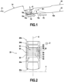
Figure 2 is a schematic representation of a top view of a vehicle according to a first embodiment of the present disclosure; -
Figure 3 is a schematic partial perspective view of the roof assembly ofFigure 2 ; -
Figure 4 is a schematic representation of a transverse cross section (viewed along section A-A) illustrating a portion of the roof assembly ofFigure 3 ; -
Figure 5 is a schematic partial enlarged view of the step-shaped segment 34d ofFigure 4 ; -
Figure 6 is a schematic perspective representation of the roof assembly portion ofFigure 4 . - A
vehicle 20 in accordance with a first embodiment of the present disclosure is schematically illustrated in a top view onFigure 2 , in a partial perspective view onFigure 3 and in a cross section along a cut plane A-A inFigure 4 . - This vehicle, e.g. a motor vehicle, an electric vehicle or an hybrid vehicle, comprises a
front part 20a and arear part 20b that are both aligned along a longitudinal direction X. -
Vehicle 20 comprises aroof assembly 22 that comprises: - a roof or roof panel 24 (represented by a rectangle in dotted lines on
Figure 2 ) extending along the longitudinal direction X and having twolongitudinal sides first front end 24a of the roof to a second oppositerear end 24b of the latter; - at least one side member that is generally part of a frame or structure of the vehicle, is connected to one of the two
longitudinal sides roof 24; in the present embodiment twoside members longitudinal sides - at least one roof reinforcement member arranged below the
roof 24 in a vertical direction of the roof assembly (this direction Z is perpendicular to the plane ofFigure 2 ; the vertical direction is considered when the vehicle is on the ground and the longitudinal direction X is generally horizontal) and that extends transversally relative to the longitudinal direction X of the roof along a transverse or lateral direction Y, from a first end to a second opposite end of the roof reinforcement member; in the present embodiment severalroof reinforcement members Figure 2 . The number and position of the roof reinforcement members can vary and are not limited to the representation on the Figures. - The following description applies to the
roof reinforcement member 34 that is more particularly represented onFigures 3 and 4 but applies equally to the other roof reinforcement members located under the roof whatever their number and position. - The
roof reinforcement member 34 has afirst end 34a and a secondopposite end 34b and is connected, through one of its first and second opposite ends called the fixed end, herefirst end 34a, to theroof 24 from the underside thereof and to thefirst side member 30 as will be detailed later. - The same connexion arrangement applies to the second opposed
end 34b (fig. 3 ), also called fixed end and that is connected to theroof 24 from the underside thereof and to thesecond side member 32. - As more particularly represented in
Figure 4 , thefirst end 34a is arranged between the longitudinal side orflange 26 of theroof 24 and an inner end orflange 30a of thefirst side member 30 so as to form a sandwiched configuration in which thefirst end 34a is interposed betweenlongitudinal side 26 andinner end 30a in a vertical stacking arrangement along vertical direction denoted Z. To be noted that the different components of this superimposed configuration have flat portions substantially perpendicular to their stacking direction so as to be easily fixed to one another. Practically, thefirst end 34a can be first fixed to thelongitudinal side 26, e.g. through welding, and then the resulting welded assembly can be fixed, e.g. welded, toinner end 30a. - More particularly, the
roof reinforcement member 34 comprises acentral segment 34c that is located between thefirst end 34a and the secondopposite end 34b and extends in a central portion of the roof assembly 22 (fig. 3 ). - This
central segment 34c is also fixed to theroof 24 from the underside thereof (in a known manner, not represented in the drawings) in order to vertically support the roof in its central portion above the inner cabin of the vehicle where occupants can sit. - As shown in
Figure 4 , theroof reinforcement member 34 further comprises a step-shapedsegment 34d that is arranged between thefirst end 34a and thecentral segment 34c (although not represented, a similar or identical arrangement may be present between the secondopposed end 34b of theroof reinforcement member 34 and thecentral segment 34c). - In the present embodiment the step-shaped
segment 34d extends away from thefirst end 34a in a downward direction D1, i.e. away from theroof 24, so as to join thefirst end 34a and thecentral segment 34c. Bothfirst end 34a andcentral segment 34c are not aligned with each other but they are aligned respectively along parallel axes a1 and a2 as shown inFigure 4 . - Thanks to this configuration, in case of a side or lateral crash scenario involving the
side member 30, the latter is subjected to side external forces (arrow F1 onFigure 4 ) oriented towards the inner (or central part) of the vehicle. These external forces propagate through theside member 30 from theouter periphery 30b thereof towards the innerfree end 30a of the side member. The propagated forces (arrow F2) push inwardly, along axis a1, the innerfree end 30a to which thefirst end 34a is fixed as previously described. These forces thus apply on the upper part of the step-shapedsegment 34d. As the transversal roofdent reinforcement member 34 is fixed both to theroof 24 from underside (not represented) and to the otheropposite side member 32 through itssecond end 34b (fig. 3 ), according to the action-reaction principle an opposite reaction force F3 (fig. 4 ) applies along axis a2 (vertically downwardly shifted relative to axis a1) on the lower part of the step-shapedsegment 34d. The two opposed forces F2 and F3 applied to vertically shifted parts of the step-shapedsegment 34d respectively along parallel axes a1 and a2 cause downwardly-oriented buckling of the step-shapedsegment 34d, as shown in dotted lines with the buckled shape B2. This buckling phenomenon is mainly directed downwardly and does no longer extend upwardly towards theroof panel 24 as in the prior art, which thus makes it possible to remedy the prior art drawbacks (welded joint failure, e.g. spot weld failure, and opening of the vehicle cabin to the exterior along with the associated safety issues for the cabin vehicle occupants). - The downwardly-oriented (away from roof 24) step-shaped
segment 34d makes it possible to control the mechanical deformation of this segment when submitted to a side or lateral crash scenario as described above and, more particularly, to orient the deformation (buckling) mainly in a downward direction and also sideways towards the outer of the vehicle as shown by the arrow F4 inFigure 4 which is oriented at an angle (downwardly and outwardly) with respect to axes a1 and a2. This favoured buckling direction provides greater safety for occupants as their heads do not run the risk of being injured by the deformation as it would be the case with a downwardly and inwardly oriented buckling direction. - The step-shaped
segment 34d is represented schematically onFigure 4 with a vertical (or slightly inclined to the vertical Z) or abrupt step to explain the principle underlying the invention. As illustrated inFigure 4 , the step-shapedsegment 34d may be slightly inclined to the perpendicular between axes a1 and a2, i.e. between direction for extension ofend 34a andcentral segment 34c. - However, as illustrated in
Figures 4 to 6 , the step-shapedsegment 34d may take a less steep shape and may comprise at least a first convex portion 34d1 proximate thefirst end 34a and a second concave portion 34d2 away from thefirst end 34a (and proximate thecentral segment 34c). The steepness of the step depends on the height to length ratio of the step. A high height to length ratio may be better to resist side crash safety as a more significant step may more easily control buckle in the desired direction. However, a sufficient mechanical rigidity has to be provided to theroof panel 24 by the roofdent reinforcement member 34. In this respect, a too high ratio may make the roofdent reinforcement member 34 weaker against mechanical forces that would be applied in a perpendicular direction to the roof panel 24 (up-down direction of vehicle). - Thus, both requirements have to be satisfied: 1) crash safety and 2) roof rigidity (strength against dentability) and the skilled person would find an optimized ratio based on iterations of shapes with some different height to length ratios and then test for each the above performances regarding both criteria 1) and 2), before selecting the optimized shape.
- The second concave portion 34d2 may follow immediately the first convex portion 34d1, i.e. no intermediate portion is arranged between the two previously defined portions.
- Alternatively, as shown in
Figure 5 , a third intermediate portion 34d3 may be arranged so as to connect the first convex portion 34d1 and the secondconcave portion 34d. This arrangement may be useful to connect the two inverted curved shapes. The selection of the length (axial extension) of the third intermediate portion 34d3 may prove to be useful in order to adjust the proper height or vertical offset between the two axes a1 and a2 with both inverted curved shapes 34d1 and 34d2 of predetermined sizes. - The third intermediate portion 34d3 may be a flat portion.
- According to an embodiment, at least one of the first convex portion 34d1 and the second concave portion 34d2 may comprise a portion of cylinder that is defined by a curvature radius.
- According to a further embodiment, the first convex portion 34d1 may have a curvature radius in the range lying between 0.1 and 10mm and the second concave portion 34d2 may have a curvature radius in the range lying between 0.1 and 10mm.
- Whatever the configuration of the step-shaped
segment 34d, it is to be noted that this segment which extends in a transverse direction (Y), or left-right vehicle direction, from thefirst end 34a towards thecentral segment 34c and vertically (Z) may have, in an embodiment, no wall flanking this segment and that would extend vertically with respect to the latter. In other words, the step-shapedsegment 34d is substantially flat in shape along its direction of extension. - A side wall could increase the force required to cause buckling of the step-shaped
segment 34d. As a consequence, the buckling could be delayed, and this could change the deformation mode of the structure during crash. - However, in another embodiment for a different vehicle geometry, this might not be the case and a side wall can be beneficial instead. This depends on the vehicle geometry and the target deformation modes during crash.
- The above description may apply to vehicle roof assemblies having different detailed configurations than that represented on the Figures and that will be described hereinafter.
- More particularly, the
side member 30 which has an elongate shape along longitudinal direction X in its portion adjacent the roof 24 (figs. 2 and3 ) has a transverse or cross section as shown inFigures 4 and6 and may comprise, from anouter end 30b, opposed to theend 30a, an outer curved, here convex,portion 30b, followed by a step-shapedportion 30d which comprises a first downwardly-extending wall 30d1, a substantially perpendicular edge 30d2 (here horizontal) and a second downwardly-extending wall 30d3 that is slightly inclined outwardly with respect to the edge so as to form a recess or setback. Thefree end 30a (ex: flange), which has a rather flat (here substantially horizontal) configuration extends away from the wall 30d3 towards the reinforcement members. - The
roof 24, as shown in theFigure 4 cross section, comprises acentral portion 24c which extends towards itslongitudinal side 26 through a substantiallyflat portion 24d that is lower thancentral portion 24c and connected thereto by asmooth descending step 24e. Theportion 24d extends outwardly until a downwardly-extendingstep 24f which is followed by a further downwardly-extendingwall 24g, slightly inclined inwardly with respect to thestep 24e so as to from a recess or setback. Thelongitudinal side 26 ends with aflat portion 24h (ex: flange) that extends outwardly parallel to thefirst end 34a andfree end 30a. The two facing configurations with the edge 30d2 and following inclined wall 30d3 on one side and thestep 24f and the followinginclined wall 24g on the opposite side form a kind of dovetail configuration. Amoulding part 50 is arranged in this location between the side member and thelongitudinal side 26 of theroof 24 and rests against the horizontal flat portions (edge 30d2 and lower portion of thestep 24f) at the upper part ofmoulding part 50. Themoulding part 50, e.g. made of soft rubber, serves as a tight-sealing member between the two components above the previously-described stacking arrangement of elements (flat portion orflange 24h,first end 34a andfree end 30a) and also serves to hide the welded portions (spot welding flanges) 24h, 34a and 30a and ensure good appearance of the vehicle roof. The extending lower legs of themoulding part 50 deform after assembly to ensure some sealing by contacting the adjacent components and also to maintain their position. -
Figure 6 shows further details of an exemplaryroof reinforcement member 34. - In particular, the
first end 34a which lies between thefree end 30a and theend portion 24h extends axially away from the stacking arrangement through the terminating edge of thefree end 34a. Then theroof reinforcement member 34 takes the form of the downwardly-extending step-shapedsegment 34d before connecting with the downwardly offsetcentral segment 34c. - As represented in
Figure 6 , thecentral segment 34c starts after the concave portion 34d2, and extends away therefrom both axially along the axis a2 and along an oblique ascending direction towards the roofcentral portion 24c across the whole width of the reinforcing member (same width as for the step-shapedsegment 34d). Thecentral segment 34c thus forms a central body delimited by bottom, upper and side or lateral surfaces 34c1, 34c2, 34c3 (the opposite side or lateral surface is hidden on the view) with an oblique front surface 34c4 that gradually raises the level of the central segment above axis a1 and through a level located below the roofcentral portion 24c so as to enable fixing (in a known manner) between the two elements at predetermined locations, not represented in the drawing. - As already mentioned above, the particular configuration (details, shapes, dimensions, etc.) of the
side member 30, theroof 24 and theroof reinforcement member 34 may vary depending on the vehicle and different constraints. - Also, the above description of these elements applies to the other side of the roof where the
side member 32 is located and the same controlled buckling deformation occurs in a case a side crash scenario occurs on the other vehicle side.
Claims (13)
- A roof assembly (22) for a vehicle (20) comprising:- a roof (24) extending along a longitudinal direction (X) between a front and a rear part of the vehicle and having two longitudinal sides,- a side member (30, 32) connected to one of the two longitudinal sides (26, 28) of the roof,- at least one roof reinforcement member (34-42) arranged below the roof in a vertical direction (Z) of the roof assembly and extending transversally relative to the longitudinal direction of the roof from a first end (34a) to a second opposite end (34b), the at least one roof reinforcement member being connected, through one of its first and second opposite ends called the fixed end (34a), to the roof (24) from the underside thereof and to the side member (32), the at least one roof reinforcement member comprising a central segment (34c) between both first (34a) and second (34b) opposite ends,characterized in that the at least one roof reinforcement member (34) comprises a step-shaped segment (34d) that extends in a downward direction away from the roof, the step-shaped segment (34b) being arranged between the fixed end (34a) of the at least one roof reinforcement member and the central segment (34c) thereof.
- The roof assembly according to claim 1, characterized in that it comprises another side member (32) connected to the other longitudinal side (28) of the roof, the at least one roof reinforcement member (34) being connected through the other end (34b) of its first and second opposite ends to the roof (24) from the underside thereof and to the other side member (32), the at least one roof reinforcement member comprises a step-shaped segment that extends in a downward direction away from the roof, the step-shaped segment being arranged between the other end (34b) of the at least one roof reinforcement member and the central segment (34bc thereof.
- The roof assembly according to claim 1 or 2, characterized in that the step-shaped segment (34d) is deprived of any side wall extending in a vertical direction along the transverse extending direction of the at least one roof reinforcement member.
- The roof assembly according to any preceding claim, characterized in that the step-shaped segment (34d) comprises, along the transverse extending direction of the at least one roof reinforcement member, a first convex portion (34d1) proximate the fixed end (34a) of the at least one roof reinforcement member and a second concave portion (34d2) away from the fixed end.
- The roof assembly according to claim 4, characterized in that the second concave portion (34d2) follows immediately the first convex portion (34d1) .
- The roof assembly according to claim 4, characterized in that the step-shaped segment (34d) comprises a third intermediate portion (34d3) connecting the first convex portion (34d1) and the second concave portion (34d2).
- The roof assembly according to claim 6, characterized in that the third intermediate portion (34d3) is a flat portion.
- The roof assembly according to any one of claims 4 to 7, characterized in that at least one of the first convex portion (34d1) and the second concave portion (34d2) comprises a portion of cylinder that is defined by a curvature radius.
- The roof assembly according to claim 8, characterized in that the first convex portion (34d1) has a curvature radius in the range between 0.1 and 10mm.
- The roof assembly according to claim 8, characterized in that the second concave portion (34d2) has a curvature radius in the range between 0.1 and 10mm.
- The roof assembly according to any preceding claim, characterized in that the fixed end (34a) of the at least one roof reinforcement member (34) comprises a flat portion.
- The roof assembly according to any preceding claim, characterized in that the at least one roof reinforcement member comprises a plurality of roof reinforcement members (34-40) extending each transversally relative to the longitudinal direction (X) of the roof (24) and being separate from each other along the longitudinal direction of the roof.
- A vehicle (20) comprising a roof assembly (22) according to any preceding claim.
Priority Applications (1)
| Application Number | Priority Date | Filing Date | Title |
|---|---|---|---|
| EP22175530.9A EP4282737A1 (en) | 2022-05-25 | 2022-05-25 | A side crash resistant roof assembly for a vehicle |
Applications Claiming Priority (1)
| Application Number | Priority Date | Filing Date | Title |
|---|---|---|---|
| EP22175530.9A EP4282737A1 (en) | 2022-05-25 | 2022-05-25 | A side crash resistant roof assembly for a vehicle |
Publications (1)
| Publication Number | Publication Date |
|---|---|
| EP4282737A1 true EP4282737A1 (en) | 2023-11-29 |
Family
ID=81850039
Family Applications (1)
| Application Number | Title | Priority Date | Filing Date |
|---|---|---|---|
| EP22175530.9A Pending EP4282737A1 (en) | 2022-05-25 | 2022-05-25 | A side crash resistant roof assembly for a vehicle |
Country Status (1)
| Country | Link |
|---|---|
| EP (1) | EP4282737A1 (en) |
Citations (3)
| Publication number | Priority date | Publication date | Assignee | Title |
|---|---|---|---|---|
| JPH10152070A (en) * | 1996-11-26 | 1998-06-09 | Nissan Motor Co Ltd | Body roof structure |
| EP1927533A1 (en) * | 2006-11-29 | 2008-06-04 | Toyota Jidosha Kabushiki Kaisha | Vehicle body side portion structure |
| US20160129944A1 (en) * | 2013-11-14 | 2016-05-12 | Mazda Motor Corporation | Vehicle body structure of vehicle side portion |
-
2022
- 2022-05-25 EP EP22175530.9A patent/EP4282737A1/en active Pending
Patent Citations (3)
| Publication number | Priority date | Publication date | Assignee | Title |
|---|---|---|---|---|
| JPH10152070A (en) * | 1996-11-26 | 1998-06-09 | Nissan Motor Co Ltd | Body roof structure |
| EP1927533A1 (en) * | 2006-11-29 | 2008-06-04 | Toyota Jidosha Kabushiki Kaisha | Vehicle body side portion structure |
| US20160129944A1 (en) * | 2013-11-14 | 2016-05-12 | Mazda Motor Corporation | Vehicle body structure of vehicle side portion |
Similar Documents
| Publication | Publication Date | Title |
|---|---|---|
| US7644978B2 (en) | Vehicle floor structure for a motor vehicle | |
| US6817654B2 (en) | Reinforcing structure for body frame of vehicle | |
| EP1943137B1 (en) | Bottom structure of vehicle body | |
| RU2681512C1 (en) | Vehicle front part design | |
| CN101190693A (en) | body side structure | |
| KR101553187B1 (en) | Structure for side portion of vehicle body | |
| CN110612246A (en) | rear body structure of the vehicle | |
| US10814915B2 (en) | Vehicle center pillar | |
| US20240083513A1 (en) | Rocker insert with plurality of enclosed sections | |
| JP4483753B2 (en) | Body superstructure | |
| JP2021146752A (en) | Automobile body | |
| EP4282737A1 (en) | A side crash resistant roof assembly for a vehicle | |
| CN114056435A (en) | Side body structure of vehicle | |
| JP7522808B2 (en) | Underbody structure | |
| CN102642755A (en) | Elevator car frame | |
| WO2024238818A1 (en) | Castellated structural member for vehicle body structure | |
| JP7824116B2 (en) | Vehicle subframe | |
| JP7063174B2 (en) | Vehicle seat rail mounting structure | |
| JP7595513B2 (en) | Vehicle underbody structure | |
| JP2022083969A (en) | Vehicle body structure for reinforcing pop-up seat mounting portion | |
| JP7525822B2 (en) | Vehicle pillar structure | |
| JP7504343B2 (en) | Vehicle underfloor structure | |
| JP7779049B2 (en) | Body floor structure | |
| CN116472217B (en) | Vehicle load-bearing structures with closed hollow profiles, especially longitudinal beams, and vehicle frame structures with at least one such load-bearing structure. | |
| JP2021024405A (en) | Floor tunnel structure for vehicle body |
Legal Events
| Date | Code | Title | Description |
|---|---|---|---|
| PUAI | Public reference made under article 153(3) epc to a published international application that has entered the european phase |
Free format text: ORIGINAL CODE: 0009012 |
|
| STAA | Information on the status of an ep patent application or granted ep patent |
Free format text: STATUS: REQUEST FOR EXAMINATION WAS MADE |
|
| 17P | Request for examination filed |
Effective date: 20220525 |
|
| AK | Designated contracting states |
Kind code of ref document: A1 Designated state(s): AL AT BE BG CH CY CZ DE DK EE ES FI FR GB GR HR HU IE IS IT LI LT LU LV MC MK MT NL NO PL PT RO RS SE SI SK SM TR |
|
| STAA | Information on the status of an ep patent application or granted ep patent |
Free format text: STATUS: EXAMINATION IS IN PROGRESS |
|
| 17Q | First examination report despatched |
Effective date: 20240909 |