EP4282668B1 - Pneumatic tire - Google Patents
Pneumatic tire Download PDFInfo
- Publication number
- EP4282668B1 EP4282668B1 EP21921189.3A EP21921189A EP4282668B1 EP 4282668 B1 EP4282668 B1 EP 4282668B1 EP 21921189 A EP21921189 A EP 21921189A EP 4282668 B1 EP4282668 B1 EP 4282668B1
- Authority
- EP
- European Patent Office
- Prior art keywords
- tire
- radial direction
- bead
- tire radial
- less
- Prior art date
- Legal status (The legal status is an assumption and is not a legal conclusion. Google has not performed a legal analysis and makes no representation as to the accuracy of the status listed.)
- Active
Links
Images

Classifications
-
- B—PERFORMING OPERATIONS; TRANSPORTING
- B60—VEHICLES IN GENERAL
- B60C—VEHICLE TYRES; TYRE INFLATION; TYRE CHANGING; CONNECTING VALVES TO INFLATABLE ELASTIC BODIES IN GENERAL; DEVICES OR ARRANGEMENTS RELATED TO TYRES
- B60C15/00—Tyre beads, e.g. ply turn-up or overlap
- B60C15/06—Flipper strips, fillers, or chafing strips and reinforcing layers for the construction of the bead
- B60C15/0603—Flipper strips, fillers, or chafing strips and reinforcing layers for the construction of the bead characterised by features of the bead filler or apex
-
- B—PERFORMING OPERATIONS; TRANSPORTING
- B60—VEHICLES IN GENERAL
- B60C—VEHICLE TYRES; TYRE INFLATION; TYRE CHANGING; CONNECTING VALVES TO INFLATABLE ELASTIC BODIES IN GENERAL; DEVICES OR ARRANGEMENTS RELATED TO TYRES
- B60C13/00—Tyre sidewalls; Protecting, decorating, marking, or the like, thereof
- B60C13/04—Tyre sidewalls; Protecting, decorating, marking, or the like, thereof having annular inlays or covers, e.g. white sidewalls
-
- B—PERFORMING OPERATIONS; TRANSPORTING
- B60—VEHICLES IN GENERAL
- B60C—VEHICLE TYRES; TYRE INFLATION; TYRE CHANGING; CONNECTING VALVES TO INFLATABLE ELASTIC BODIES IN GENERAL; DEVICES OR ARRANGEMENTS RELATED TO TYRES
- B60C13/00—Tyre sidewalls; Protecting, decorating, marking, or the like, thereof
- B60C2013/005—Physical properties of the sidewall rubber
- B60C2013/007—Thickness
-
- B—PERFORMING OPERATIONS; TRANSPORTING
- B60—VEHICLES IN GENERAL
- B60C—VEHICLE TYRES; TYRE INFLATION; TYRE CHANGING; CONNECTING VALVES TO INFLATABLE ELASTIC BODIES IN GENERAL; DEVICES OR ARRANGEMENTS RELATED TO TYRES
- B60C15/00—Tyre beads, e.g. ply turn-up or overlap
- B60C15/06—Flipper strips, fillers, or chafing strips and reinforcing layers for the construction of the bead
- B60C15/0603—Flipper strips, fillers, or chafing strips and reinforcing layers for the construction of the bead characterised by features of the bead filler or apex
- B60C2015/061—Dimensions of the bead filler in terms of numerical values or ratio in proportion to section height
-
- B—PERFORMING OPERATIONS; TRANSPORTING
- B60—VEHICLES IN GENERAL
- B60C—VEHICLE TYRES; TYRE INFLATION; TYRE CHANGING; CONNECTING VALVES TO INFLATABLE ELASTIC BODIES IN GENERAL; DEVICES OR ARRANGEMENTS RELATED TO TYRES
- B60C15/00—Tyre beads, e.g. ply turn-up or overlap
- B60C15/06—Flipper strips, fillers, or chafing strips and reinforcing layers for the construction of the bead
- B60C2015/0614—Flipper strips, fillers, or chafing strips and reinforcing layers for the construction of the bead characterised by features of the chafer or clinch portion, i.e. the part of the bead contacting the rim
-
- Y—GENERAL TAGGING OF NEW TECHNOLOGICAL DEVELOPMENTS; GENERAL TAGGING OF CROSS-SECTIONAL TECHNOLOGIES SPANNING OVER SEVERAL SECTIONS OF THE IPC; TECHNICAL SUBJECTS COVERED BY FORMER USPC CROSS-REFERENCE ART COLLECTIONS [XRACs] AND DIGESTS
- Y02—TECHNOLOGIES OR APPLICATIONS FOR MITIGATION OR ADAPTATION AGAINST CLIMATE CHANGE
- Y02T—CLIMATE CHANGE MITIGATION TECHNOLOGIES RELATED TO TRANSPORTATION
- Y02T10/00—Road transport of goods or passengers
- Y02T10/80—Technologies aiming to reduce greenhouse gasses emissions common to all road transportation technologies
- Y02T10/86—Optimisation of rolling resistance, e.g. weight reduction
-
- Y—GENERAL TAGGING OF NEW TECHNOLOGICAL DEVELOPMENTS; GENERAL TAGGING OF CROSS-SECTIONAL TECHNOLOGIES SPANNING OVER SEVERAL SECTIONS OF THE IPC; TECHNICAL SUBJECTS COVERED BY FORMER USPC CROSS-REFERENCE ART COLLECTIONS [XRACs] AND DIGESTS
- Y10—TECHNICAL SUBJECTS COVERED BY FORMER USPC
- Y10T—TECHNICAL SUBJECTS COVERED BY FORMER US CLASSIFICATION
- Y10T152/00—Resilient tires and wheels
- Y10T152/10—Tires, resilient
- Y10T152/10495—Pneumatic tire or inner tube
- Y10T152/10819—Characterized by the structure of the bead portion of the tire
- Y10T152/10828—Chafer or sealing strips
-
- Y—GENERAL TAGGING OF NEW TECHNOLOGICAL DEVELOPMENTS; GENERAL TAGGING OF CROSS-SECTIONAL TECHNOLOGIES SPANNING OVER SEVERAL SECTIONS OF THE IPC; TECHNICAL SUBJECTS COVERED BY FORMER USPC CROSS-REFERENCE ART COLLECTIONS [XRACs] AND DIGESTS
- Y10—TECHNICAL SUBJECTS COVERED BY FORMER USPC
- Y10T—TECHNICAL SUBJECTS COVERED BY FORMER US CLASSIFICATION
- Y10T152/00—Resilient tires and wheels
- Y10T152/10—Tires, resilient
- Y10T152/10495—Pneumatic tire or inner tube
- Y10T152/10819—Characterized by the structure of the bead portion of the tire
- Y10T152/10837—Bead characterized by the radial extent of apex, flipper or chafer into tire sidewall
-
- Y—GENERAL TAGGING OF NEW TECHNOLOGICAL DEVELOPMENTS; GENERAL TAGGING OF CROSS-SECTIONAL TECHNOLOGIES SPANNING OVER SEVERAL SECTIONS OF THE IPC; TECHNICAL SUBJECTS COVERED BY FORMER USPC CROSS-REFERENCE ART COLLECTIONS [XRACs] AND DIGESTS
- Y10—TECHNICAL SUBJECTS COVERED BY FORMER USPC
- Y10T—TECHNICAL SUBJECTS COVERED BY FORMER US CLASSIFICATION
- Y10T152/00—Resilient tires and wheels
- Y10T152/10—Tires, resilient
- Y10T152/10495—Pneumatic tire or inner tube
- Y10T152/10819—Characterized by the structure of the bead portion of the tire
- Y10T152/10846—Bead characterized by the chemical composition and or physical properties of elastomers or the like
Definitions
- the present invention relates to a pneumatic tire.
- JP2017121899A discloses a pneumatic tire that comprises a tread, and a pair of side walls respectively extending substantially inward in a nearly radial direction from an end of the tread.
- a profile of the pneumatic tire ranging from a shoulder part of the tread to the side walls comprises: an inner circular arc constituting profiles of inner parts in a radial direction of the side walls; an outer circular arc positioned outside in the radial direction of the inner circular arc; a shoulder circular arc constituting a profile of the shoulder part; and a straight line, positioned between the outer circular arc and the shoulder circular arc, which contacts the outer circular arc and the shoulder circular arc.
- a ratio (Ro/Ri) of a curvature radius of the outer circular arc relative to a curvature radius of the inner circular arc is 0.60 or more and less than 0.85.
- JP2020055468A discloses a tire that includes a carcass, a belt layer, and a band layer.
- a band ply formed by coating a band cord with topping rubber is spirally wound, and a gap, which is formed when side edges of the band ply adjacent in a tire axial direction separate from each other, is included.
- the band layer includes a crown part having a tire equator, and shoulder parts on both outer sides. A width in the tire axial direction of the gap at the crown part is smaller than a width in the tire axial direction of the gap at the shoulder part.
- WO2016035840A1 discloses a tire having a filler layered on a clinch on the outside in the axial direction of a carcass.
- a carcass ply of the carcass is folded around a core of a bead.
- a folded portion of the carcass ply is positioned between the filler and an apex.
- the clinch has a maximum thickness Tcx as measured along the normal to an inner surface in the axial direction of the clinch.
- the normal for the thickness Tcx is a first reference line L1
- the ratio of a thickness Tf1 of the filler as measured along the first reference line to the sum of the thickness Tf1 and the thickness Tcx is 0.1 to 0.6 inclusive.
- the percentage of the complex modulus of elasticity E*f of the filler to the complex modulus of elasticity E*a of the apex of the bead is 70% to 125% inclusive.
- a “storage modulus” refers to a value measured at a temperature of 25°C in accordance with JIS K7244.
- a "rim separation point” refers to a point at which an outer surface of the tire separates from the rim flange when the pneumatic tire is in a reference state in which it is mounted on the applicable rim, a specified internal pressure is applied, and no load is applied.
- an "applicable rim” refers to a standard rim (which is called a measuring rim in STANDARDS MANUAL of the European Tyre and Rim Technical Organisation [ETRTO], and a design rim in YEAR BOOK of the Tire and Rim Association, Inc. [TRA]) of an applicable size that is described or will be described in industrial standards valid for a region in which the tire is produced or used.
- industrial standards include JATMA Year Book of the Japan Automobile Tyre Manufacturers Association (JATMA) in Japan, STANDARDS MANUAL of the ETRTO in Europe, and YEAR BOOK of the TRA in the United States of America (that is, the "rim” includes any size currently included and any size which will be possibly included in the industrial standards.
- a “rim” refers to a rim having a width corresponding to the bead width of the tire.
- a “specified internal pressure” refers to an air pressure (maximum air pressure) corresponding to the maximum load capability of a single wheel of an applicable size/ply rating specified by the JATMA or the like.
- a “specified internal pressure” refers to an air pressure (maximum air pressure) corresponding to the maximum load capability determined depending on a vehicle to which the tire is mounted.
- a pneumatic tire that can prevent a decrease in cornering power can be provided.
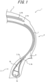
- FIG. 1 is a partial cross-sectional view taken along a tire width direction of a pneumatic tire (hereinafter referred to simply as a tire) according to an embodiment of the present invention.
- FIG. 1 illustrates a cross-section in the tire width direction in the aforementioned reference state.
- the tire 1 includes a pair of bead cores 2a embedded in a pair of bead portions 2, and a carcass 3 including one or more carcass plies extending in a toroidal form between the pair of bead cores 2a.
- bead fillers 2b are disposed on an outer side in a tire radial direction of the bead cores 2a.
- the bead cores 2a in this example include a plurality of bead wires that are surrounded by a rubber coating.
- the bead wires in this example are formed by steel cords.
- the bead fillers 2b are made of rubber or the like and have a substantially triangular cross-sectional shape with a thickness decreasing toward the outer side in the tire radial direction.
- the height of the bead fillers 2b (measured in the tire radial direction) is preferably 8 to 25 mm, as in this example. This is because setting the height of the bead fillers 2b to 8 mm or more can prevent air entry during manufacturing, while setting the height of the bead fillers 2b to 25 mm or less can reduce the weight of the tire. For the same reason, it is more preferable to set the height of the bead fillers 2b to 10 to 15 mm.
- the carcass 3 in this example includes a carcass body portion 3a that extends in a toroidal form between the pair of bead portions 2, and carcass fold-up portions 3b that are folded from the carcass body portion 3a around the bead cores 2a from the inner side in the tire width direction to the outer side in the tire width direction.
- Organic fibers such as PET, hybrid cords made of two types of organic fiber cords (e.g., nylon and aramid) twisted together, or the like may be used as carcass cords.
- the carcass plies are plies of radially arranged cords.
- outer ends in the tire radial direction of the carcass fold-up portions 3b are located further inward in the tire radial direction than the tire maximum width position and are located further outward in the tire radial direction than outer ends in the tire radial direction of the bead fillers 2b.
- a belt 4 which includes one or more (two in the illustrated example) belt layers 4a and 4b.
- Belt cords of the belt layers 4a and 4b intersect each other between the layers and extend at an inclination angle of 30° to 60° in this example with respect to a tire circumferential direction.
- Steel cords can be used for the belt cords, but organic fiber cords can also be used to reduce weight.
- a tread portion 5 made of tread rubber is disposed on the outer side in the tire radial direction of the belt 4.
- the rubber gauge thickness of rubber measured in a direction perpendicular to outer surfaces of the sidewall portions 6 in the cross-section in the tire width direction in the aforementioned reference state
- the rubber gauge at the tire maximum width position is preferably 1 mm or more but 3 mm or less, as in this example. Setting the rubber gauge at the tire maximum width position to 1 mm or more can ensure minimum side-cut resistance, while setting the rubber gauge at the maximum width position of the tire to 3 mm or less can reduce the weight of the tire.
- the tire 1 according to the present embodiment is provided with a reinforcing member 7, which extends at an angle with respect to the tire radial direction in an area including the tire maximum width position that stretches in the tire radial direction on the outer side in the tire width direction of the carcass 3.
- the reinforcing member 7 has an arc shape along the carcass body portion 3a in the cross-section, but it may have other shapes, such as a straight line.
- the "tire maximum width position” refers to a position where the width in the tire width direction of the pneumatic tire becomes maximum in the cross-section in the tire width direction in the aforementioned reference state.
- the reinforcing member 7 includes organic fiber cords.
- the organic fiber cords include organic fibers, such as PET, or hybrid cords made of two types of organic fiber cords (e.g., a nylon cord and an aramid cord) twisted together.
- the Young's modulus of the cords of the reinforcing member 7 (tested by JIS L1017 8.5 a] [2002] and determined in accordance with JIS L1017 8.8 [2002]) is not particularly limited, but can be 3000 to 5000 GPa, the number of cords of the reinforcing member 7 can be 20 to 70 cords/50 mm, and the cord diameter of the cords of the reinforcing member 7 can be 0.3 to 0.9 mm.
- one layer of reinforcing member from the viewpoint of weight reduction, two or more layers can be disposed, and in such cases, it is preferable to adjust the Young's modulus, the number, and the diameter of the cords so that they can be reduced to be substantially equal to those of one layer in terms of stiffness and weight reduction.
- the reinforcing member 7 preferably extends at an angle of 30° to 60° with respect to the tire radial direction, and more preferably, it extends at an angle of 40° to 50° with respect to the tire radial direction.
- the length in the tire radial direction of the reinforcing member 7 is preferably 10 to 40% of the height of the cross-section of the tire. Setting the length to 10% or more can improve cornering power, while setting the length to 40% or less can reduce weight increase.
- the tire 1 according to the present embodiment is provided with rubber chafers 8 on the outer side in the tire width direction of the bead fillers 2b.
- the length in the tire radial direction of the rubber chafers 8 is preferably 30 to 60 mm.
- Outer ends in the tire radial direction of the rubber chafers 8 are preferably located further outward in the tire radial direction than the rim separation point. Inner ends in the tire radial direction of the rubber chafers 8 are preferably located further inward in the tire radial direction than inner ends in the tire radial direction of the bead cores 2a. As illustrated in FIG. 1 , in this example, the rubber chafers 8 extend further outward in the tire radial direction than the apex of a rim guard from the vicinity of a bead base line (imaginary line passing through bead bases and extending parallel to the tire width direction) in an area stretching in the tire radial direction.
- a bead base line imaging line passing through bead bases and extending parallel to the tire width direction
- the height of the bead fillers 2b is 25 mm or less (in this example, furthermore, the outer ends in the tire radial direction of the carcass fold-up portions 3b are located further inward in the tire radial direction than the tire maximum width position, and the rubber gauge at the tire maximum width position is 3 mm or less, and the material of the carcass cords is an organic fiber, such as PET, or a hybrid cord made of two types of organic fibers). Accordingly, the weight of the tire can be reduced. As mentioned above, such a tire may suffer a decrease in cornering power due to a decrease in lateral spring coefficient.
- the out-of-plane bending acts as a tensile force on the side of the bead portion 2 that is closer to a tire inner surface, while also acting as a compressive force on the side of the bead portion that is close to the tire outer surface, and that a decrease in lateral spring coefficient can be prevented, in particular by withstanding the compressive force on the side of the bead portion 2 that is closer to the tire outer surface (inner side of the bending).
- the highly rigid (0.4 ⁇ E2'/E1' ⁇ 1) rubber chafers 8 are disposed on the outer side in the tire width direction of the bead fillers 2b as described above.
- the highly rigid rubber chafers 8 can prevent an increase in the rotational component of the lateral displacement, thus preventing a decrease in lateral spring coefficient, thereby preventing a decrease in cornering power.
- the pneumatic tire according to the present invention can prevent a decrease in cornering power, while reducing the weight of the tire.
- the aforementioned lightweight configuration As in the present embodiment, even in a case in which the aforementioned lightweight configuration is not adopted, the effect of preventing a decrease in cornering power can be obtained, because the highly rigid rubber chafers 8 can prevent an increase in the rotational component of lateral displacement due to a compressive force acting on the side of the bead portions 2 that is closer to the tire outer surface.
- the ratio E2'/E1' preferably further satisfies 0.6 ⁇ E 2 ' / E 1 ' ⁇ 1 .
- the length in the tire radial direction of the rubber chafers is preferably 30 to 60 mm. Setting the length to 30 mm or more can more fully provide the effect of preventing an increase in the rotational component of lateral displacement, while setting the length to 60 mm or less can minimize weight increase due to the disposition of the rubber chafers.
- the outer ends in the tire radial direction of the rubber chafers are preferably located further outward in the tire radial direction than the rim separation point. That way, a wider area on which out-of-plane bending acts is covered, and the effect of preventing an increase in the rotational component of lateral displacement can be more fully obtained.
- the inner ends in the tire radial direction of the rubber chafers are preferably located further inward in the tire radial direction than the inner ends in the tire radial direction of the bead cores. That way, a wider area on which out-of-plane bending acts is covered, and the effect of preventing an increase in the rotational component of lateral displacement can be more fully obtained.
- the tire according to the present invention is preferably a pneumatic radial tire for passenger vehicles.
- the tire has a shape with a narrow width and a large diameter, with a tire cross-sectional width SW of less than 165 (mm) and with a ratio SW/OD of the tire cross-sectional width SW to the outer diameter OD of 0.26 or less.
- Setting the tire cross-sectional width SW to be narrower than the tire outer diameter OD can reduce air resistance, and increasing the tire outer diameter OD relative to the tire cross-sectional width SW can prevent deformation of the tread rubber in the vicinity of a ground-contacting surface of the tire, thereby reducing rolling resistance. This can improve the fuel efficiency of the tire.
- the ratio SW/OD is preferably 0.25 or less, and more preferably 0.24 or less.
- the above ratio is preferably satisfied when the internal pressure of the tire is 200 kPa or more, more preferably when it is 220 kPa or more, and even more preferably when it is 280 kPa or more. This is because rolling resistance can be reduced. On the other hand, the above ratio is preferably satisfied when the internal pressure of the tire is 350 kPa or less. This is because ride comfort can be improved.
- the tire cross-sectional width SW is preferably 105 mm or more, more preferably 125 mm or more, even more preferably 135 mm or more, and particularly preferably 145 mm or more, within the range in which the above ratio is satisfied.
- the tire cross-sectional width SW is preferably 155 mm or less, within the range in which the above ratio is satisfied.
- the tire outer diameter OD is preferably 500 mm or more, more preferably 550 mm or more, and even more preferably 580 mm or more, within the range in which the above ratio is satisfied.
- the tire outer diameter OD is preferably 800 mm or less, more preferably 720 mm or less, even more preferably 650 mm or less, and particularly preferably 630 mm or less, within the range in which the above ratio is satisfied.
- the rim diameter is preferably 16 inches or more, more preferably 17 inches or more, and even more preferably 18 inches or more, providing that the tire cross-sectional width SW and the outer diameter OD satisfy the above ratio.
- the rim diameter is preferably 22 inches or less, more preferably 21 inches or less, even more preferably 20 inches or less, and particularly preferably 19 inches or less, providing that the tire cross-sectional width SW and the outer diameter OD satisfy the above ratio.
- the aspect ratio of the tire is preferably 45 to 70, and more preferably 45 to 65, providing that the tire cross-sectional width SW and the outer diameter OD satisfy the above ratio.
- the specific size of the tire may be, but is not particularly limited to, 105/50R16, 115/50R17, 125/55R20, 125/60R18, 125/65R19, 135/45R21, 135/55R20, 135/60R17, 135/60R18, 135/60R19, 135/65R19, 145/45R21, 145/55R20, 145/60R16, 145/60R17, 145/60R18, 145/60R19, 145/65R19, 155/45R18, 155/45R21, 155/55R18, 155/55R19, 155/55R21, 155/60R17, 155/65R18, 155/70R17, or 155/70R19.
- the tire has a shape with a narrow width and a large diameter, with a tire cross-sectional width SW of 165 (mm) or more, wherein the tire cross-sectional width SW (mm) and the outer diameter OD (mm) satisfy the relational expression OD mm ⁇ 2.135 ⁇ SW mm + 282.3 .
- the ratio SW/OD is preferably 0.26 or less, more preferably 0.25 or less, and even more preferably 0.24 or less, providing that the tire cross-sectional width SW and the outer diameter OD satisfy the above expressional expression. This is because the fuel efficiency of the tire can be further improved.
- the above relational expression and/or the ratio are/is preferably satisfied when the internal pressure of the tire is 200 kPa or more, more preferably when it is 220 kPa or more, and even more preferably when it is 280 kPa or more. This is because rolling resistance can be reduced. On the other hand, the above relational expression and/or the ratio are/is satisfied when the internal pressure of the tire is 350 kPa or less. This is because ride comfort can be improved.
- the tire cross-sectional width SW is preferably 175 mm or more, and more preferably 185 mm or more, within the range in which the above relational expression is satisfied.
- the tire cross-sectional width SW is preferably 230 mm or less, more preferably 215 mm or less, even more preferably 205 mm or less, and particularly preferably 195 mm or less, within the range in which the above relational expression is satisfied.
- the tire outer diameter OD is preferably 630 mm or more, and more preferably 650 mm or more, within the range in which the above relational expression is satisfied.
- the tire outer diameter OD is preferably 800 mm or less, more preferably 750 mm or less, and even more preferably 720 mm or less, within the range in which the above relational expression is satisfied.
- the rim diameter is preferably 18 inches or more, and more preferably 19 inches or more, providing that the tire cross-sectional width SW and the outer diameter OD satisfy the above relational expression.
- the rim diameter is preferably 22 inches or less, and more preferably 21 inches or less, providing that the tire cross-sectional width SW and the outer diameter OD satisfy the above relational expression.
- the aspect ratio of the tire is preferably 45 to 70, and more preferably 45 to 65, providing that the tire cross-sectional width SW and the outer diameter OD satisfy the above relational expression.
- the specific size of the tire may be, but is not particularly limited to, 165/45R22, 165/55R18, 165/55R19, 165/55R20, 165/55R21, 165/60R19, 165/65R19, 165/70R18, 175/45R23, 175/55R 19, 175/55R20, 175/55R22, 175/60R18, 185/45R22, 185/50R20, 185/55R19, 185/55R20, 185/60R19, 185/60R20, 195/50R20, 195/55R20, 195/60R19, 205/50R 21, 205/55R20, or 215/50R21.
- the tire has a shape with a narrow width and a large diameter, wherein the tire cross-sectional width SW (mm) and the outer diameter OD (mm) satisfy the relational expression OD mm ⁇ -0 . 0187 ⁇ SW mm 2 + 9.15 ⁇ SW mm - 380 .
- the ratio SW/OD is preferably 0.26 or less, more preferably 0.25 or less, and even more preferably 0.24 or less, providing that the tire cross-sectional width SW and the outer diameter OD satisfy the above expressional expression. This is because the fuel efficiency of the tire can be further improved.
- the above relational expression and/or the ratio are/is preferably satisfied when the internal pressure of the tire is 200 kPa or more, more preferably when it is 220 kPa or more, and even more preferably when it is 280 kPa or more. This is because rolling resistance can be reduced.
- the above relational expression and/or the ratio are/is preferably satisfied when the internal pressure of the tire is 350 kPa or less. This is because ride comfort can be improved.
- the tire cross-sectional width SW is preferably 105 mm or more, more preferably 125 mm or more, even more preferably 135 mm or more, and particularly preferably 145 mm or more, within the range in which the above relational expression is satisfied.
- the tire cross-sectional width SW is preferably 230 mm or less, more preferably 215 mm or less, even more preferably 205 mm or less, and particularly preferably 195 mm or less, within the range in which the above relational expression is satisfied.
- the tire outer diameter OD is preferably 500 mm or more, more preferably 550 mm or more, and even more preferably 580 mm or more, within the range in which the above relational expression is satisfied.
- the tire outer diameter OD is preferably 800 mm or less, more preferably 750 mm or less, and even more preferably 720 mm or less, within the range in which the above relational expression is satisfied.
- the rim diameter is preferably 16 inches or more, more preferably 17 inches or more, and even more preferably 18 inches or more, providing that the tire cross-sectional width SW and the outer diameter OD satisfy the above relational expression.
- the rim diameter is preferably 22 inches or less, more preferably 21 inches or less, and even more preferably 20 inches or less, providing that the tire cross-sectional width SW and the outer diameter OD satisfy the above relational expression.
- the aspect ratio of the tire is preferably 45 to 70, and more preferably 45 to 65, providing that the tire cross-sectional width SW and the outer diameter OD satisfy the above relational expression.
- the specific size of the tire may be, but is not particularly limited to, 105/50R16, 115/50R17, 125/55R20, 125/60R18, 125/65R19, 135/45R21, 135/55R20, 135/60R17, 135/60R18, 135/60R19, 135/65R19, 145/45R21, 145/55R20, 145/60R16, 145/60R17, 145/60R18, 145/60R19, 145/65R19, 155/45R18, 155/45R21, 155/55R18, 155/55R19, 155/55R21, 155/60R17, 155/65R18, 155/70R17, 155/70R19, 165/45R22, 165/55R18, 165/55R19, 165/55R20, 165/55R21, 165/60R19, 165/6R
- a tire with the aforementioned lightweight configuration may suffer a decrease in cornering power due to a decrease in lateral spring coefficient.
- the present inventors have conducted studies and found that the cause of a decrease in lateral spring coefficient is that lateral displacement is concentrated directly under the load and the surrounding area is pulled in the direction of the load, causing an increase in shear deformation on the circumference.
- the tire according to the present embodiment is provided with the reinforcing member 7, which extends at an angle with respect to the tire radial direction in an area including the tire maximum width position that stretches in the tire radial direction on the outer side in the tire width direction of the carcass 3.
- the reinforcing member preferably includes organic fiber cords. Since organic fibers are lightweight despite their rigidity, weight increase due to the addition of the reinforcing member can be minimized.
- the reinforcing member preferably extends at an angle of 30° to 60° with respect to the tire radial direction, and more preferably, it extends at an angle of 40° to 50° with respect to the tire radial direction.
- the effect of preventing shear deformation illustrated schematically in FIG. 4 becomes most significant when the inclination angle of the reinforcing member with respect to the tire radial direction is close to approximately 45°, and therefore, setting the above range can further prevent a decrease in cornering power.
- the length in the tire radial direction of the reinforcing member is preferably 10 to 40% of the height of the cross-section of the tire. Setting the length to 10% or more further ensures that the effect of preventing a decrease in cornering power can be obtained, while setting the length to 40% or less can minimize weight increase due to the addition of the reinforcing member.
- an outer end in the tire radial direction of the reinforcing member can be at a position corresponding to 50 to 80% of the height of the cross-section of the tire from the bead base line (imaginary line passing through bead bases and extending parallel to the tire width direction), and an inner end in the tire radial direction of the reinforcing member can be at a position corresponding 15 to 40% of the height of the cross-section of the tire from the bead base line.
- the length in the tire radial direction of the reinforcing member can be, but is not particularly limited to, 15 to 40 mm.
- Example tire, Comparative Example tire, and Conventional Example tire were experimentally produced, and their performance was evaluated.
- Each tire includes: a pair of bead cores embedded in a pair of bead portions; and a carcass including one or more carcass plies extending in a toroidal form between the pair of bead cores, wherein bead fillers are disposed on an outer side in a tire radial direction of the bead cores, and rubber chafers are provided on an outer side in a tire width direction of the bead fillers.
- Table 1 The specifications of each tire are summarized in Table 1 below.
- “side portion” means “sidewall portion”
- side portion gauge” means a rubber gauge at a tire maximum width position.
- BF is an abbreviation for "bead filler”
- GC rubber chafer
Landscapes
- Engineering & Computer Science (AREA)
- Mechanical Engineering (AREA)
- Tires In General (AREA)
- Developing Agents For Electrophotography (AREA)
Description
- The present invention relates to a pneumatic tire.
- In general, it is desirable to increase the cornering power of pneumatic tires.
- Especially in recent years, fuel efficiency can be improved by simplifying tire structures and reducing their weights, such as by thinning rubber in the sidewall portions or reducing the height of the bead fillers (for example, Patent Literature 1 [PTL 1]). In such cases, there is a concern about a decrease in cornering power, due to a decrease in lateral spring coefficient in particular.
-
JP2017121899A -
JP2020055468A -
WO2016035840A1 discloses a tire having a filler layered on a clinch on the outside in the axial direction of a carcass. A carcass ply of the carcass is folded around a core of a bead. A folded portion of the carcass ply is positioned between the filler and an apex. The clinch has a maximum thickness Tcx as measured along the normal to an inner surface in the axial direction of the clinch. When the normal for the thickness Tcx is a first reference line L1, the ratio of a thickness Tf1 of the filler as measured along the first reference line to the sum of the thickness Tf1 and the thickness Tcx is 0.1 to 0.6 inclusive. The percentage of the complex modulus of elasticity E*f of the filler to the complex modulus of elasticity E*a of the apex of the bead is 70% to 125% inclusive. - PTL 1:
JP 2019-137327 A - It would be helpful to provide a pneumatic tire that can prevent a decrease in cornering power.
- The problem is solved by a tire according to claim 1.
- Herein, a "storage modulus" refers to a value measured at a temperature of 25°C in accordance with JIS K7244.
- Furthermore, a "rim separation point", which will be described below, refers to a point at which an outer surface of the tire separates from the rim flange when the pneumatic tire is in a reference state in which it is mounted on the applicable rim, a specified internal pressure is applied, and no load is applied.
- Herein, an "applicable rim" refers to a standard rim (which is called a measuring rim in STANDARDS MANUAL of the European Tyre and Rim Technical Organisation [ETRTO], and a design rim in YEAR BOOK of the Tire and Rim Association, Inc. [TRA]) of an applicable size that is described or will be described in industrial standards valid for a region in which the tire is produced or used. Examples of the industrial standards include JATMA Year Book of the Japan Automobile Tyre Manufacturers Association (JATMA) in Japan, STANDARDS MANUAL of the ETRTO in Europe, and YEAR BOOK of the TRA in the United States of America (that is, the "rim" includes any size currently included and any size which will be possibly included in the industrial standards. Examples of the "size which will be described" include those described as "FUTURE DEVELOPMENTS" in the ETRTO 2013 edition). As for sizes not described in the industrial standards, a "rim" refers to a rim having a width corresponding to the bead width of the tire.
- Moreover, a "specified internal pressure" refers to an air pressure (maximum air pressure) corresponding to the maximum load capability of a single wheel of an applicable size/ply rating specified by the JATMA or the like. As for sizes not described in the industrial standards, a "specified internal pressure" refers to an air pressure (maximum air pressure) corresponding to the maximum load capability determined depending on a vehicle to which the tire is mounted.
- According to the present invention, a pneumatic tire that can prevent a decrease in cornering power can be provided.
- In the accompanying drawings:
-
FIG. 1 is a partial cross-sectional view taken along a tire width direction of a pneumatic tire according to an embodiment of the present invention; and -
FIG. 2 schematically illustrates out-of-plane bending acting on a bead portion. - In the following, embodiments of the present invention will be described in detail by illustration with reference to the drawings.
-
FIG. 1 is a partial cross-sectional view taken along a tire width direction of a pneumatic tire (hereinafter referred to simply as a tire) according to an embodiment of the present invention.FIG. 1 illustrates a cross-section in the tire width direction in the aforementioned reference state. - The tire 1 includes a pair of
bead cores 2a embedded in a pair ofbead portions 2, and a carcass 3 including one or more carcass plies extending in a toroidal form between the pair ofbead cores 2a. - In the
bead portions 2,bead fillers 2b are disposed on an outer side in a tire radial direction of thebead cores 2a. Thebead cores 2a in this example include a plurality of bead wires that are surrounded by a rubber coating. The bead wires in this example are formed by steel cords. In this example, thebead fillers 2b are made of rubber or the like and have a substantially triangular cross-sectional shape with a thickness decreasing toward the outer side in the tire radial direction. - Here, the height of the
bead fillers 2b (measured in the tire radial direction) is preferably 8 to 25 mm, as in this example. This is because setting the height of thebead fillers 2b to 8 mm or more can prevent air entry during manufacturing, while setting the height of thebead fillers 2b to 25 mm or less can reduce the weight of the tire. For the same reason, it is more preferable to set the height of thebead fillers 2b to 10 to 15 mm. - The carcass 3 in this example includes a carcass body portion 3a that extends in a toroidal form between the pair of
bead portions 2, and carcass fold-up portions 3b that are folded from the carcass body portion 3a around thebead cores 2a from the inner side in the tire width direction to the outer side in the tire width direction. Organic fibers, such as PET, hybrid cords made of two types of organic fiber cords (e.g., nylon and aramid) twisted together, or the like may be used as carcass cords. As mentioned above, the carcass plies are plies of radially arranged cords. - In this example, outer ends in the tire radial direction of the carcass fold-up portions 3b are located further inward in the tire radial direction than the tire maximum width position and are located further outward in the tire radial direction than outer ends in the tire radial direction of the
bead fillers 2b. With this configuration, the weight of the tire can be further reduced. - As illustrated in
FIG. 1 , on the outer side in the tire radial direction of a crown portion of the carcass 3, there is a belt 4, which includes one or more (two in the illustrated example) belt layers 4a and 4b. Belt cords of the belt layers 4a and 4b intersect each other between the layers and extend at an inclination angle of 30° to 60° in this example with respect to a tire circumferential direction. Steel cords can be used for the belt cords, but organic fiber cords can also be used to reduce weight. Atread portion 5 made of tread rubber is disposed on the outer side in the tire radial direction of the belt 4. - As illustrated in
FIG. 1 , a pair ofsidewall portions 6 are connected between the pair ofbead portions 2 and thetread portion 5. Here, the rubber gauge (thickness of rubber measured in a direction perpendicular to outer surfaces of thesidewall portions 6 in the cross-section in the tire width direction in the aforementioned reference state) at the tire maximum width position is preferably 1 mm or more but 3 mm or less, as in this example. Setting the rubber gauge at the tire maximum width position to 1 mm or more can ensure minimum side-cut resistance, while setting the rubber gauge at the maximum width position of the tire to 3 mm or less can reduce the weight of the tire. - Here, as illustrated in
FIG. 1 , the tire 1 according to the present embodiment is provided with a reinforcingmember 7, which extends at an angle with respect to the tire radial direction in an area including the tire maximum width position that stretches in the tire radial direction on the outer side in the tire width direction of the carcass 3. Additionally, in the illustrated example, the reinforcingmember 7 has an arc shape along the carcass body portion 3a in the cross-section, but it may have other shapes, such as a straight line. Here, the "tire maximum width position" refers to a position where the width in the tire width direction of the pneumatic tire becomes maximum in the cross-section in the tire width direction in the aforementioned reference state. - In this example, the reinforcing
member 7 includes organic fiber cords. Examples the organic fiber cords include organic fibers, such as PET, or hybrid cords made of two types of organic fiber cords (e.g., a nylon cord and an aramid cord) twisted together. The Young's modulus of the cords of the reinforcing member 7 (tested by JIS L1017 8.5 a] [2002] and determined in accordance with JIS L1017 8.8 [2002]) is not particularly limited, but can be 3000 to 5000 GPa, the number of cords of the reinforcingmember 7 can be 20 to 70 cords/50 mm, and the cord diameter of the cords of the reinforcingmember 7 can be 0.3 to 0.9 mm. Although it is preferable to dispose one layer of reinforcing member from the viewpoint of weight reduction, two or more layers can be disposed, and in such cases, it is preferable to adjust the Young's modulus, the number, and the diameter of the cords so that they can be reduced to be substantially equal to those of one layer in terms of stiffness and weight reduction. - As in this example, the reinforcing
member 7 preferably extends at an angle of 30° to 60° with respect to the tire radial direction, and more preferably, it extends at an angle of 40° to 50° with respect to the tire radial direction. - The length in the tire radial direction of the reinforcing
member 7 is preferably 10 to 40% of the height of the cross-section of the tire. Setting the length to 10% or more can improve cornering power, while setting the length to 40% or less can reduce weight increase. - Here, as illustrated in
FIG. 1 , the tire 1 according to the present embodiment is provided withrubber chafers 8 on the outer side in the tire width direction of thebead fillers 2b. The length in the tire radial direction of therubber chafers 8 is preferably 30 to 60 mm. - Outer ends in the tire radial direction of the
rubber chafers 8 are preferably located further outward in the tire radial direction than the rim separation point. Inner ends in the tire radial direction of therubber chafers 8 are preferably located further inward in the tire radial direction than inner ends in the tire radial direction of thebead cores 2a. As illustrated inFIG. 1 , in this example, therubber chafers 8 extend further outward in the tire radial direction than the apex of a rim guard from the vicinity of a bead base line (imaginary line passing through bead bases and extending parallel to the tire width direction) in an area stretching in the tire radial direction. - According to the invention, the
rubber chafers 7 are made of highly elastic rubber, and specifically, when the storage modulus of thebead fillers 2b is E1' and the storage modulus of therubber chafers 7 is E2', the ratio E2'/E1' satisfies
- Advantageous effects of the pneumatic tire according to the present invention will be described below.
- In the pneumatic tire according to the present invention, first of all, the height of the
bead fillers 2b is 25 mm or less (in this example, furthermore, the outer ends in the tire radial direction of the carcass fold-up portions 3b are located further inward in the tire radial direction than the tire maximum width position, and the rubber gauge at the tire maximum width position is 3 mm or less, and the material of the carcass cords is an organic fiber, such as PET, or a hybrid cord made of two types of organic fibers). Accordingly, the weight of the tire can be reduced. As mentioned above, such a tire may suffer a decrease in cornering power due to a decrease in lateral spring coefficient. - To address the above, the present inventors have conducted studies and found that an increased rotational component of lateral displacement, among translation, rotational, and bending components, is the cause of a decrease in lateral spring coefficient, when out-of-plane bending acts on a
bead portion 2 as schematically illustrated inFIG. 2 (in particular, in a case in which the height of thebead fillers 2b is set to 25 mm or less as mentioned above, the stiffness of the bead portions decreases, and the degree of out-of-plane bending increases). Furthermore, as schematically illustrated inFIG. 2 , it has been found that the out-of-plane bending acts as a tensile force on the side of thebead portion 2 that is closer to a tire inner surface, while also acting as a compressive force on the side of the bead portion that is close to the tire outer surface, and that a decrease in lateral spring coefficient can be prevented, in particular by withstanding the compressive force on the side of thebead portion 2 that is closer to the tire outer surface (inner side of the bending). This is the reason why the highly rigid (0.4 ≤ E2'/E1' ≤ 1)rubber chafers 8 are disposed on the outer side in the tire width direction of thebead fillers 2b as described above. As a result, even when a compressive force acts on the side thebead portions 2 that is closer to the tire outer surface, the highlyrigid rubber chafers 8 can prevent an increase in the rotational component of the lateral displacement, thus preventing a decrease in lateral spring coefficient, thereby preventing a decrease in cornering power. - When the ratio E2'/E1' is less than 0.4, the effect of preventing an increase in the rotational component of the lateral displacement cannot be fully achieved. On the other hand, when the ratio E2'/E1' is greater than 1, friction coefficient at the contact area with the rim decreases, causing a concern that the tire may come off the rim.
- As described above, the pneumatic tire according to the present invention can prevent a decrease in cornering power, while reducing the weight of the tire.
- Although it is particularly effective in the aforementioned lightweight configuration as in the present embodiment, even in a case in which the aforementioned lightweight configuration is not adopted, the effect of preventing a decrease in cornering power can be obtained, because the highly
rigid rubber chafers 8 can prevent an increase in the rotational component of lateral displacement due to a compressive force acting on the side of thebead portions 2 that is closer to the tire outer surface. - Here, for the same reason as above, the ratio E2'/E1' preferably further satisfies

- The length in the tire radial direction of the rubber chafers is preferably 30 to 60 mm. Setting the length to 30 mm or more can more fully provide the effect of preventing an increase in the rotational component of lateral displacement, while setting the length to 60 mm or less can minimize weight increase due to the disposition of the rubber chafers.
- The outer ends in the tire radial direction of the rubber chafers are preferably located further outward in the tire radial direction than the rim separation point. That way, a wider area on which out-of-plane bending acts is covered, and the effect of preventing an increase in the rotational component of lateral displacement can be more fully obtained.
- The inner ends in the tire radial direction of the rubber chafers are preferably located further inward in the tire radial direction than the inner ends in the tire radial direction of the bead cores. That way, a wider area on which out-of-plane bending acts is covered, and the effect of preventing an increase in the rotational component of lateral displacement can be more fully obtained.
- The tire according to the present invention is preferably a pneumatic radial tire for passenger vehicles.
- In an example, the tire has a shape with a narrow width and a large diameter, with a tire cross-sectional width SW of less than 165 (mm) and with a ratio SW/OD of the tire cross-sectional width SW to the outer diameter OD of 0.26 or less. Setting the tire cross-sectional width SW to be narrower than the tire outer diameter OD can reduce air resistance, and increasing the tire outer diameter OD relative to the tire cross-sectional width SW can prevent deformation of the tread rubber in the vicinity of a ground-contacting surface of the tire, thereby reducing rolling resistance. This can improve the fuel efficiency of the tire. The ratio SW/OD is preferably 0.25 or less, and more preferably 0.24 or less.
- The above ratio is preferably satisfied when the internal pressure of the tire is 200 kPa or more, more preferably when it is 220 kPa or more, and even more preferably when it is 280 kPa or more. This is because rolling resistance can be reduced. On the other hand, the above ratio is preferably satisfied when the internal pressure of the tire is 350 kPa or less. This is because ride comfort can be improved.
- From the viewpoint of maintaining the ground contact area, the tire cross-sectional width SW is preferably 105 mm or more, more preferably 125 mm or more, even more preferably 135 mm or more, and particularly preferably 145 mm or more, within the range in which the above ratio is satisfied. On the other hand, from the viewpoint of reducing air resistance, the tire cross-sectional width SW is preferably 155 mm or less, within the range in which the above ratio is satisfied. From the viewpoint of reducing rolling resistance, the tire outer diameter OD is preferably 500 mm or more, more preferably 550 mm or more, and even more preferably 580 mm or more, within the range in which the above ratio is satisfied. On the other hand, from the viewpoint of reducing air resistance, the tire outer diameter OD is preferably 800 mm or less, more preferably 720 mm or less, even more preferably 650 mm or less, and particularly preferably 630 mm or less, within the range in which the above ratio is satisfied. From the viewpoint of reducing rolling resistance, the rim diameter is preferably 16 inches or more, more preferably 17 inches or more, and even more preferably 18 inches or more, providing that the tire cross-sectional width SW and the outer diameter OD satisfy the above ratio. On the other hand, from the viewpoint of reducing air resistance, the rim diameter is preferably 22 inches or less, more preferably 21 inches or less, even more preferably 20 inches or less, and particularly preferably 19 inches or less, providing that the tire cross-sectional width SW and the outer diameter OD satisfy the above ratio. The aspect ratio of the tire is preferably 45 to 70, and more preferably 45 to 65, providing that the tire cross-sectional width SW and the outer diameter OD satisfy the above ratio.
- In an example, the specific size of the tire may be, but is not particularly limited to, 105/50R16, 115/50R17, 125/55R20, 125/60R18, 125/65R19, 135/45R21, 135/55R20, 135/60R17, 135/60R18, 135/60R19, 135/65R19, 145/45R21, 145/55R20, 145/60R16, 145/60R17, 145/60R18, 145/60R19, 145/65R19, 155/45R18, 155/45R21, 155/55R18, 155/55R19, 155/55R21, 155/60R17, 155/65R18, 155/70R17, or 155/70R19.
- In another example, the tire has a shape with a narrow width and a large diameter, with a tire cross-sectional width SW of 165 (mm) or more, wherein the tire cross-sectional width SW (mm) and the outer diameter OD (mm) satisfy the relational expression

- By satisfying the above relational expression, air resistance can be reduced, and rolling resistance can be reduced, whereby the fuel efficiency of the tire can be improved.
- In a second embodiment, the ratio SW/OD is preferably 0.26 or less, more preferably 0.25 or less, and even more preferably 0.24 or less, providing that the tire cross-sectional width SW and the outer diameter OD satisfy the above expressional expression. This is because the fuel efficiency of the tire can be further improved.
- The above relational expression and/or the ratio are/is preferably satisfied when the internal pressure of the tire is 200 kPa or more, more preferably when it is 220 kPa or more, and even more preferably when it is 280 kPa or more. This is because rolling resistance can be reduced. On the other hand, the above relational expression and/or the ratio are/is satisfied when the internal pressure of the tire is 350 kPa or less. This is because ride comfort can be improved.
- Here, from the viewpoint of maintaining the ground contact area, the tire cross-sectional width SW is preferably 175 mm or more, and more preferably 185 mm or more, within the range in which the above relational expression is satisfied. On the other hand, from the viewpoint of reducing air resistance, the tire cross-sectional width SW is preferably 230 mm or less, more preferably 215 mm or less, even more preferably 205 mm or less, and particularly preferably 195 mm or less, within the range in which the above relational expression is satisfied. From the viewpoint of reducing rolling resistance, the tire outer diameter OD is preferably 630 mm or more, and more preferably 650 mm or more, within the range in which the above relational expression is satisfied. On the other hand, from the viewpoint of reducing air resistance, the tire outer diameter OD is preferably 800 mm or less, more preferably 750 mm or less, and even more preferably 720 mm or less, within the range in which the above relational expression is satisfied. Furthermore, from the viewpoint of reducing rolling resistance, the rim diameter is preferably 18 inches or more, and more preferably 19 inches or more, providing that the tire cross-sectional width SW and the outer diameter OD satisfy the above relational expression. On the other hand, from the viewpoint of reducing air resistance, the rim diameter is preferably 22 inches or less, and more preferably 21 inches or less, providing that the tire cross-sectional width SW and the outer diameter OD satisfy the above relational expression. Moreover, the aspect ratio of the tire is preferably 45 to 70, and more preferably 45 to 65, providing that the tire cross-sectional width SW and the outer diameter OD satisfy the above relational expression.
- In an example, the specific size of the tire may be, but is not particularly limited to, 165/45R22, 165/55R18, 165/55R19, 165/55R20, 165/55R21, 165/60R19, 165/65R19, 165/70R18, 175/45R23, 175/55R 19, 175/55R20, 175/55R22, 175/60R18, 185/45R22, 185/50R20, 185/55R19, 185/55R20, 185/60R19, 185/60R20, 195/50R20, 195/55R20, 195/60R19, 205/50R 21, 205/55R20, or 215/50R21.
- In yet another example, the tire has a shape with a narrow width and a large diameter, wherein the tire cross-sectional width SW (mm) and the outer diameter OD (mm) satisfy the relational expression

- By satisfying the above relational expression, air resistance can be reduced, and rolling resistance can be reduced, whereby the fuel efficiency of the tire can be improved.
- In a third embodiment, the ratio SW/OD is preferably 0.26 or less, more preferably 0.25 or less, and even more preferably 0.24 or less, providing that the tire cross-sectional width SW and the outer diameter OD satisfy the above expressional expression. This is because the fuel efficiency of the tire can be further improved.
- The above relational expression and/or the ratio are/is preferably satisfied when the internal pressure of the tire is 200 kPa or more, more preferably when it is 220 kPa or more, and even more preferably when it is 280 kPa or more. This is because rolling resistance can be reduced. On the other hand, the above relational expression and/or the ratio are/is preferably satisfied when the internal pressure of the tire is 350 kPa or less. This is because ride comfort can be improved.
- Here, from the viewpoint of maintaining the ground contact area, the tire cross-sectional width SW is preferably 105 mm or more, more preferably 125 mm or more, even more preferably 135 mm or more, and particularly preferably 145 mm or more, within the range in which the above relational expression is satisfied. On the other hand, from the viewpoint of reducing air resistance, the tire cross-sectional width SW is preferably 230 mm or less, more preferably 215 mm or less, even more preferably 205 mm or less, and particularly preferably 195 mm or less, within the range in which the above relational expression is satisfied. From the viewpoint of reducing rolling resistance, the tire outer diameter OD is preferably 500 mm or more, more preferably 550 mm or more, and even more preferably 580 mm or more, within the range in which the above relational expression is satisfied. On the other hand, from the viewpoint of reducing air resistance, the tire outer diameter OD is preferably 800 mm or less, more preferably 750 mm or less, and even more preferably 720 mm or less, within the range in which the above relational expression is satisfied. Furthermore, from the viewpoint of reducing rolling resistance, the rim diameter is preferably 16 inches or more, more preferably 17 inches or more, and even more preferably 18 inches or more, providing that the tire cross-sectional width SW and the outer diameter OD satisfy the above relational expression. On the other hand, from the viewpoint of reducing air resistance, the rim diameter is preferably 22 inches or less, more preferably 21 inches or less, and even more preferably 20 inches or less, providing that the tire cross-sectional width SW and the outer diameter OD satisfy the above relational expression. Moreover, the aspect ratio of the tire is preferably 45 to 70, and more preferably 45 to 65, providing that the tire cross-sectional width SW and the outer diameter OD satisfy the above relational expression.
- In an example, the specific size of the tire may be, but is not particularly limited to, 105/50R16, 115/50R17, 125/55R20, 125/60R18, 125/65R19, 135/45R21, 135/55R20, 135/60R17, 135/60R18, 135/60R19, 135/65R19, 145/45R21, 145/55R20, 145/60R16, 145/60R17, 145/60R18, 145/60R19, 145/65R19, 155/45R18, 155/45R21, 155/55R18, 155/55R19, 155/55R21, 155/60R17, 155/65R18, 155/70R17, 155/70R19, 165/45R22, 165/55R18, 165/55R19, 165/55R20, 165/55R21, 165/60R19, 165/6R19, 165/70R18, 175/45R23, 175/55R18, 175/55R19, 175/55R20, 175/55R22, 175/60R18, 185/45R22, 185/50R20, 185/55R19, 185/55R20, 185/60R19, 185/60R20, 195/50R20, 195/55R20, 195/60R19, 205/50R21, 205/55R20, or 215/50R21.
- Here, as mentioned above, a tire with the aforementioned lightweight configuration may suffer a decrease in cornering power due to a decrease in lateral spring coefficient. The present inventors have conducted studies and found that the cause of a decrease in lateral spring coefficient is that lateral displacement is concentrated directly under the load and the surrounding area is pulled in the direction of the load, causing an increase in shear deformation on the circumference. For this reason, the tire according to the present embodiment is provided with the reinforcing
member 7, which extends at an angle with respect to the tire radial direction in an area including the tire maximum width position that stretches in the tire radial direction on the outer side in the tire width direction of the carcass 3. As a result, two forces pulling in opposite direction act on the reinforcingmember 7 during shear deformation, thereby reducing the shear deformation. This can prevent a decrease in lateral spring coefficient and further prevents a decrease in cornering power. Although it is particularly effective in the aforementioned lightweight configuration as in the present embodiment, even in a case in which the aforementioned lightweight configuration is not adopted, the effect of further preventing a decrease in cornering power can be obtained, because two forces pulling in the opposite directions act on the reinforcingmember 7 during shearing deformation. - Here, the reinforcing member preferably includes organic fiber cords. Since organic fibers are lightweight despite their rigidity, weight increase due to the addition of the reinforcing member can be minimized.
- The reinforcing member preferably extends at an angle of 30° to 60° with respect to the tire radial direction, and more preferably, it extends at an angle of 40° to 50° with respect to the tire radial direction. The effect of preventing shear deformation illustrated schematically in FIG. 4 becomes most significant when the inclination angle of the reinforcing member with respect to the tire radial direction is close to approximately 45°, and therefore, setting the above range can further prevent a decrease in cornering power.
- The length in the tire radial direction of the reinforcing member is preferably 10 to 40% of the height of the cross-section of the tire. Setting the length to 10% or more further ensures that the effect of preventing a decrease in cornering power can be obtained, while setting the length to 40% or less can minimize weight increase due to the addition of the reinforcing member. In an example, an outer end in the tire radial direction of the reinforcing member can be at a position corresponding to 50 to 80% of the height of the cross-section of the tire from the bead base line (imaginary line passing through bead bases and extending parallel to the tire width direction), and an inner end in the tire radial direction of the reinforcing member can be at a position corresponding 15 to 40% of the height of the cross-section of the tire from the bead base line. The length in the tire radial direction of the reinforcing member can be, but is not particularly limited to, 15 to 40 mm.
- In order to verify advantageous effects of the present invention, Example tire, Comparative Example tire, and Conventional Example tire were experimentally produced, and their performance was evaluated. Each tire includes: a pair of bead cores embedded in a pair of bead portions; and a carcass including one or more carcass plies extending in a toroidal form between the pair of bead cores, wherein bead fillers are disposed on an outer side in a tire radial direction of the bead cores, and rubber chafers are provided on an outer side in a tire width direction of the bead fillers. The specifications of each tire are summarized in Table 1 below. In Table 1, "side portion" means "sidewall portion", and "side portion gauge" means a rubber gauge at a tire maximum width position. Furthermore, BF is an abbreviation for "bead filler", and GC for "rubber chafer." Lateral spring coefficients were measured, by mounting each tire on a rim, measuring the amount of deflection using an indoor tester, and measuring the lateral spring coefficient from a tangential gradient at a load of 4 kN. The weight of each tire before rim mounting was also measured. In Table 1, evaluation results are presented as an index with the Conventional Example being 100.
[Table 1] Conventional Example Comparative Example Example Side portion gauge [mm] 2.6 1 1 Reinforcing member Position Bead portion N/A Side portion Angle 45° N/A 45° GC/BF rubber hardness E2'/E1' 0.38 0.38 1 GC height [mm] 45 45 45 BF height [mm] 30 10 10 Weight [%] * the smaller the better 100 80 81 Lateral spring [%] *the greater the better 100 89 119 -
- 1
- Pneumatic tire
- 2
- Bead portion
- 3
- Carcass
- 4
- Belt
- 5
- Tread portion
- 6
- Sidewall portion
- 7
- Reinforcing member
- 8
- Rubber chafer
Claims (5)
- A pneumatic tire (1) comprising:a pair of bead cores (2a) embedded in a pair of bead portions (2); anda carcass (3) including one or more carcass plies extending in a toroidal form between the pair of bead cores, outer ends of carcass fold-up portions (3b) in a tire radial direction being located further inward in the tire radial direction than a tire maximum width position, whereinbead fillers (2b) are disposed on an outer side of the bead cores in the tire radial direction, a height of the bead fillers is 25 mm or less,rubber chafers (8) are provided on an outer side in a tire width direction of the bead fillers, andwhen a storage modulus of the bead fillers is E1', and a storage modulus of the rubber chafers is E2', the ratio E2'/E1' satisfies 0.4 ≤ E2'/E1' ≤ 1, the storage modulus referring to a value measured at a temperature of 25°C in accordance with JIS K7244;a rubber gauge at the tire maximum width position is 3 mm or less, anda material of carcass cords is an organic fiber or a hybrid cord made of two types of organic fibers.
- The pneumatic tire (1) according to claim 1, wherein the ratio E2'/E1' further satisfies

- The pneumatic tire (1) according to claim 1 or 2, wherein a length in the tire radial direction of each of the rubber chafers (8) is 30 to 60 mm.
- The pneumatic tire (1) according to any one of claims 1 to 3, wherein outer ends in the tire radial direction of the rubber chafers (8) are located further outward in the tire radial direction than a rim separation point.
- The pneumatic tire (1) according to any one of claims 1 to 4, wherein inner ends in the tire radial direction of the rubber chafers (8) are located further inward in the tire radial direction than inner ends in the tire radial direction of the bead cores (2a).
Applications Claiming Priority (2)
| Application Number | Priority Date | Filing Date | Title |
|---|---|---|---|
| JP2021009053A JP2022112984A (en) | 2021-01-22 | 2021-01-22 | pneumatic tire |
| PCT/JP2021/040880 WO2022158086A1 (en) | 2021-01-22 | 2021-11-05 | Pneumatic tire |
Publications (3)
| Publication Number | Publication Date |
|---|---|
| EP4282668A1 EP4282668A1 (en) | 2023-11-29 |
| EP4282668A4 EP4282668A4 (en) | 2024-07-24 |
| EP4282668B1 true EP4282668B1 (en) | 2025-06-04 |
Family
ID=82548682
Family Applications (1)
| Application Number | Title | Priority Date | Filing Date |
|---|---|---|---|
| EP21921189.3A Active EP4282668B1 (en) | 2021-01-22 | 2021-11-05 | Pneumatic tire |
Country Status (5)
| Country | Link |
|---|---|
| US (1) | US20240034102A1 (en) |
| EP (1) | EP4282668B1 (en) |
| JP (2) | JP2022112984A (en) |
| CN (1) | CN116648363A (en) |
| WO (1) | WO2022158086A1 (en) |
Family Cites Families (15)
| Publication number | Priority date | Publication date | Assignee | Title |
|---|---|---|---|---|
| JP4904028B2 (en) * | 2005-08-11 | 2012-03-28 | 住友ゴム工業株式会社 | Pneumatic tire |
| JP5438427B2 (en) * | 2009-08-07 | 2014-03-12 | 住友ゴム工業株式会社 | Racing cart tires |
| JP5639596B2 (en) * | 2009-11-25 | 2014-12-10 | 株式会社ブリヂストン | Heavy duty pneumatic radial tire |
| WO2013102186A2 (en) * | 2011-12-29 | 2013-07-04 | Bridgestone Corporation | Pneumatic tire |
| CN104114382B (en) * | 2012-03-14 | 2016-05-11 | 株式会社普利司通 | tire |
| JP5548793B1 (en) * | 2013-02-28 | 2014-07-16 | 株式会社ブリヂストン | Pneumatic radial tire for passenger cars |
| CN105189149B (en) * | 2013-02-28 | 2017-04-05 | 株式会社普利司通 | Pneumatic run-flat tire |
| EP3753755B1 (en) * | 2014-09-04 | 2022-11-09 | Sumitomo Rubber Industries, Ltd. | Pneumatic tire |
| JP2017121908A (en) * | 2016-01-08 | 2017-07-13 | 住友ゴム工業株式会社 | Pneumatic tire |
| JP6638402B2 (en) * | 2016-01-08 | 2020-01-29 | 住友ゴム工業株式会社 | Pneumatic tire |
| JP6772779B2 (en) * | 2016-11-22 | 2020-10-21 | 住友ゴム工業株式会社 | Pneumatic tires |
| JP7119868B2 (en) * | 2018-10-03 | 2022-08-17 | 住友ゴム工業株式会社 | tire |
| JP7299061B2 (en) * | 2019-05-13 | 2023-06-27 | Toyo Tire株式会社 | pneumatic tire |
| JP7111659B2 (en) * | 2019-06-28 | 2022-08-02 | 矢崎総業株式会社 | Appearance inspection device for terminals |
| DE112021000321B4 (en) * | 2020-02-17 | 2023-11-09 | The Yokohama Rubber Co., Ltd. | tire |
-
2021
- 2021-01-22 JP JP2021009053A patent/JP2022112984A/en active Pending
- 2021-11-05 WO PCT/JP2021/040880 patent/WO2022158086A1/en not_active Ceased
- 2021-11-05 US US18/257,585 patent/US20240034102A1/en active Pending
- 2021-11-05 EP EP21921189.3A patent/EP4282668B1/en active Active
- 2021-11-05 CN CN202180085174.0A patent/CN116648363A/en active Pending
-
2025
- 2025-04-02 JP JP2025061386A patent/JP7852118B2/en active Active
Also Published As
| Publication number | Publication date |
|---|---|
| WO2022158086A1 (en) | 2022-07-28 |
| JP2025092714A (en) | 2025-06-19 |
| EP4282668A4 (en) | 2024-07-24 |
| JP7852118B2 (en) | 2026-04-27 |
| JP2022112984A (en) | 2022-08-03 |
| US20240034102A1 (en) | 2024-02-01 |
| CN116648363A (en) | 2023-08-25 |
| EP4282668A1 (en) | 2023-11-29 |
Similar Documents
| Publication | Publication Date | Title |
|---|---|---|
| EP2810790A1 (en) | Automobile pneumatic radial tire and method of using same | |
| EP2213484A1 (en) | Pneumatic tire | |
| CN109414966B (en) | Tire with reduced weight bead area | |
| EP3281805B1 (en) | Pneumatic tire | |
| EP3189987B1 (en) | Pneumatic tire | |
| US20170355230A1 (en) | Pneumatic Tire | |
| JP2002301911A (en) | Run flat tire | |
| EP2650144B1 (en) | Pneumatic tire | |
| US7077182B2 (en) | Run-flat tire | |
| US6719029B2 (en) | Tire wall gauges to optimize runflat tire ride comfort | |
| JP7587159B2 (en) | tire | |
| EP4257371B1 (en) | Pneumatic tire | |
| EP4282668B1 (en) | Pneumatic tire | |
| EP4282667B1 (en) | Pneumatic tire | |
| EP3564045A1 (en) | Pneumatic tire for motorcycles | |
| EP3078509B1 (en) | Pneumatic tire | |
| EP3536522B1 (en) | Run flat tire | |
| JP7311779B2 (en) | run flat tires | |
| US11548327B2 (en) | Bias tire | |
| EP3189988B1 (en) | Pneumatic tire | |
| EP4640446A1 (en) | Motorcycle tire | |
| EP4635752A1 (en) | Tire | |
| EP4512639B1 (en) | Pneumatic tire | |
| EP3900954B1 (en) | Pneumatic tyre | |
| JP7131047B2 (en) | run flat tires |
Legal Events
| Date | Code | Title | Description |
|---|---|---|---|
| STAA | Information on the status of an ep patent application or granted ep patent |
Free format text: STATUS: THE INTERNATIONAL PUBLICATION HAS BEEN MADE |
|
| PUAI | Public reference made under article 153(3) epc to a published international application that has entered the european phase |
Free format text: ORIGINAL CODE: 0009012 |
|
| STAA | Information on the status of an ep patent application or granted ep patent |
Free format text: STATUS: REQUEST FOR EXAMINATION WAS MADE |
|
| 17P | Request for examination filed |
Effective date: 20230526 |
|
| AK | Designated contracting states |
Kind code of ref document: A1 Designated state(s): AL AT BE BG CH CY CZ DE DK EE ES FI FR GB GR HR HU IE IS IT LI LT LU LV MC MK MT NL NO PL PT RO RS SE SI SK SM TR |
|
| DAV | Request for validation of the european patent (deleted) | ||
| DAX | Request for extension of the european patent (deleted) | ||
| A4 | Supplementary search report drawn up and despatched |
Effective date: 20240625 |
|
| RIC1 | Information provided on ipc code assigned before grant |
Ipc: B60C 15/00 20060101ALN20240619BHEP Ipc: B60C 13/04 20060101ALI20240619BHEP Ipc: B60C 15/06 20060101AFI20240619BHEP |
|
| RIC1 | Information provided on ipc code assigned before grant |
Ipc: B60C 15/00 20060101ALN20241203BHEP Ipc: B60C 13/04 20060101ALI20241203BHEP Ipc: B60C 15/06 20060101AFI20241203BHEP |
|
| GRAP | Despatch of communication of intention to grant a patent |
Free format text: ORIGINAL CODE: EPIDOSNIGR1 |
|
| STAA | Information on the status of an ep patent application or granted ep patent |
Free format text: STATUS: GRANT OF PATENT IS INTENDED |
|
| RIC1 | Information provided on ipc code assigned before grant |
Ipc: B60C 15/00 20060101ALN20241217BHEP Ipc: B60C 13/04 20060101ALI20241217BHEP Ipc: B60C 15/06 20060101AFI20241217BHEP |
|
| INTG | Intention to grant announced |
Effective date: 20250116 |
|
| GRAS | Grant fee paid |
Free format text: ORIGINAL CODE: EPIDOSNIGR3 |
|
| GRAA | (expected) grant |
Free format text: ORIGINAL CODE: 0009210 |
|
| STAA | Information on the status of an ep patent application or granted ep patent |
Free format text: STATUS: THE PATENT HAS BEEN GRANTED |
|
| P01 | Opt-out of the competence of the unified patent court (upc) registered |
Free format text: CASE NUMBER: APP_16558/2025 Effective date: 20250404 |
|
| AK | Designated contracting states |
Kind code of ref document: B1 Designated state(s): AL AT BE BG CH CY CZ DE DK EE ES FI FR GB GR HR HU IE IS IT LI LT LU LV MC MK MT NL NO PL PT RO RS SE SI SK SM TR |
|
| REG | Reference to a national code |
Ref country code: GB Ref legal event code: FG4D |
|
| REG | Reference to a national code |
Ref country code: CH Ref legal event code: EP |
|
| REG | Reference to a national code |
Ref country code: DE Ref legal event code: R096 Ref document number: 602021031963 Country of ref document: DE |
|
| REG | Reference to a national code |
Ref country code: IE Ref legal event code: FG4D |
|
| REG | Reference to a national code |
Ref country code: NL Ref legal event code: MP Effective date: 20250604 |
|
| PG25 | Lapsed in a contracting state [announced via postgrant information from national office to epo] |
Ref country code: FI Free format text: LAPSE BECAUSE OF FAILURE TO SUBMIT A TRANSLATION OF THE DESCRIPTION OR TO PAY THE FEE WITHIN THE PRESCRIBED TIME-LIMIT Effective date: 20250604 Ref country code: ES Free format text: LAPSE BECAUSE OF FAILURE TO SUBMIT A TRANSLATION OF THE DESCRIPTION OR TO PAY THE FEE WITHIN THE PRESCRIBED TIME-LIMIT Effective date: 20250604 |
|
| REG | Reference to a national code |
Ref country code: LT Ref legal event code: MG9D |
|
| PG25 | Lapsed in a contracting state [announced via postgrant information from national office to epo] |
Ref country code: NO Free format text: LAPSE BECAUSE OF FAILURE TO SUBMIT A TRANSLATION OF THE DESCRIPTION OR TO PAY THE FEE WITHIN THE PRESCRIBED TIME-LIMIT Effective date: 20250904 Ref country code: GR Free format text: LAPSE BECAUSE OF FAILURE TO SUBMIT A TRANSLATION OF THE DESCRIPTION OR TO PAY THE FEE WITHIN THE PRESCRIBED TIME-LIMIT Effective date: 20250905 |
|
| PG25 | Lapsed in a contracting state [announced via postgrant information from national office to epo] |
Ref country code: PL Free format text: LAPSE BECAUSE OF FAILURE TO SUBMIT A TRANSLATION OF THE DESCRIPTION OR TO PAY THE FEE WITHIN THE PRESCRIBED TIME-LIMIT Effective date: 20250604 |
|
| PG25 | Lapsed in a contracting state [announced via postgrant information from national office to epo] |
Ref country code: BG Free format text: LAPSE BECAUSE OF FAILURE TO SUBMIT A TRANSLATION OF THE DESCRIPTION OR TO PAY THE FEE WITHIN THE PRESCRIBED TIME-LIMIT Effective date: 20250604 |
|
| PG25 | Lapsed in a contracting state [announced via postgrant information from national office to epo] |
Ref country code: HR Free format text: LAPSE BECAUSE OF FAILURE TO SUBMIT A TRANSLATION OF THE DESCRIPTION OR TO PAY THE FEE WITHIN THE PRESCRIBED TIME-LIMIT Effective date: 20250604 |
|
| PG25 | Lapsed in a contracting state [announced via postgrant information from national office to epo] |
Ref country code: RS Free format text: LAPSE BECAUSE OF FAILURE TO SUBMIT A TRANSLATION OF THE DESCRIPTION OR TO PAY THE FEE WITHIN THE PRESCRIBED TIME-LIMIT Effective date: 20250904 |
|
| PG25 | Lapsed in a contracting state [announced via postgrant information from national office to epo] |
Ref country code: LV Free format text: LAPSE BECAUSE OF FAILURE TO SUBMIT A TRANSLATION OF THE DESCRIPTION OR TO PAY THE FEE WITHIN THE PRESCRIBED TIME-LIMIT Effective date: 20250604 |
|
| PG25 | Lapsed in a contracting state [announced via postgrant information from national office to epo] |
Ref country code: NL Free format text: LAPSE BECAUSE OF FAILURE TO SUBMIT A TRANSLATION OF THE DESCRIPTION OR TO PAY THE FEE WITHIN THE PRESCRIBED TIME-LIMIT Effective date: 20250604 |
|
| PG25 | Lapsed in a contracting state [announced via postgrant information from national office to epo] |
Ref country code: PT Free format text: LAPSE BECAUSE OF FAILURE TO SUBMIT A TRANSLATION OF THE DESCRIPTION OR TO PAY THE FEE WITHIN THE PRESCRIBED TIME-LIMIT Effective date: 20251006 |
|
| REG | Reference to a national code |
Ref country code: AT Ref legal event code: MK05 Ref document number: 1800020 Country of ref document: AT Kind code of ref document: T Effective date: 20250604 |
|
| PG25 | Lapsed in a contracting state [announced via postgrant information from national office to epo] |
Ref country code: IS Free format text: LAPSE BECAUSE OF FAILURE TO SUBMIT A TRANSLATION OF THE DESCRIPTION OR TO PAY THE FEE WITHIN THE PRESCRIBED TIME-LIMIT Effective date: 20251004 |
|
| PGFP | Annual fee paid to national office [announced via postgrant information from national office to epo] |
Ref country code: DE Payment date: 20251119 Year of fee payment: 5 |
|
| PG25 | Lapsed in a contracting state [announced via postgrant information from national office to epo] |
Ref country code: AT Free format text: LAPSE BECAUSE OF FAILURE TO SUBMIT A TRANSLATION OF THE DESCRIPTION OR TO PAY THE FEE WITHIN THE PRESCRIBED TIME-LIMIT Effective date: 20250604 Ref country code: SM Free format text: LAPSE BECAUSE OF FAILURE TO SUBMIT A TRANSLATION OF THE DESCRIPTION OR TO PAY THE FEE WITHIN THE PRESCRIBED TIME-LIMIT Effective date: 20250604 |
|
| PGFP | Annual fee paid to national office [announced via postgrant information from national office to epo] |
Ref country code: FR Payment date: 20251126 Year of fee payment: 5 |
|
| PG25 | Lapsed in a contracting state [announced via postgrant information from national office to epo] |
Ref country code: CZ Free format text: LAPSE BECAUSE OF FAILURE TO SUBMIT A TRANSLATION OF THE DESCRIPTION OR TO PAY THE FEE WITHIN THE PRESCRIBED TIME-LIMIT Effective date: 20250604 |
|
| PG25 | Lapsed in a contracting state [announced via postgrant information from national office to epo] |
Ref country code: EE Free format text: LAPSE BECAUSE OF FAILURE TO SUBMIT A TRANSLATION OF THE DESCRIPTION OR TO PAY THE FEE WITHIN THE PRESCRIBED TIME-LIMIT Effective date: 20250604 |
|
| PG25 | Lapsed in a contracting state [announced via postgrant information from national office to epo] |
Ref country code: SK Free format text: LAPSE BECAUSE OF FAILURE TO SUBMIT A TRANSLATION OF THE DESCRIPTION OR TO PAY THE FEE WITHIN THE PRESCRIBED TIME-LIMIT Effective date: 20250604 |
|
| PG25 | Lapsed in a contracting state [announced via postgrant information from national office to epo] |
Ref country code: IT Free format text: LAPSE BECAUSE OF FAILURE TO SUBMIT A TRANSLATION OF THE DESCRIPTION OR TO PAY THE FEE WITHIN THE PRESCRIBED TIME-LIMIT Effective date: 20250604 |
|
| REG | Reference to a national code |
Ref country code: DE Ref legal event code: R097 Ref document number: 602021031963 Country of ref document: DE |
|
| PG25 | Lapsed in a contracting state [announced via postgrant information from national office to epo] |
Ref country code: RO Free format text: LAPSE BECAUSE OF FAILURE TO SUBMIT A TRANSLATION OF THE DESCRIPTION OR TO PAY THE FEE WITHIN THE PRESCRIBED TIME-LIMIT Effective date: 20250604 |
|
| PLBE | No opposition filed within time limit |
Free format text: ORIGINAL CODE: 0009261 |
|
| STAA | Information on the status of an ep patent application or granted ep patent |
Free format text: STATUS: NO OPPOSITION FILED WITHIN TIME LIMIT |
|
| PG25 | Lapsed in a contracting state [announced via postgrant information from national office to epo] |
Ref country code: DK Free format text: LAPSE BECAUSE OF FAILURE TO SUBMIT A TRANSLATION OF THE DESCRIPTION OR TO PAY THE FEE WITHIN THE PRESCRIBED TIME-LIMIT Effective date: 20250604 |
|
| REG | Reference to a national code |
Ref country code: CH Ref legal event code: L10 Free format text: ST27 STATUS EVENT CODE: U-0-0-L10-L00 (AS PROVIDED BY THE NATIONAL OFFICE) Effective date: 20260416 |