EP4282659A1 - Liquid discharge head, head module, and liquid discharge apparatus - Google Patents
Liquid discharge head, head module, and liquid discharge apparatus Download PDFInfo
- Publication number
- EP4282659A1 EP4282659A1 EP23174518.3A EP23174518A EP4282659A1 EP 4282659 A1 EP4282659 A1 EP 4282659A1 EP 23174518 A EP23174518 A EP 23174518A EP 4282659 A1 EP4282659 A1 EP 4282659A1
- Authority
- EP
- European Patent Office
- Prior art keywords
- housing
- liquid discharge
- driver
- linear expansion
- valve
- Prior art date
- Legal status (The legal status is an assumption and is not a legal conclusion. Google has not performed a legal analysis and makes no representation as to the accuracy of the status listed.)
- Granted
Links
Images



Classifications
-
- B—PERFORMING OPERATIONS; TRANSPORTING
- B41—PRINTING; LINING MACHINES; TYPEWRITERS; STAMPS
- B41J—TYPEWRITERS; SELECTIVE PRINTING MECHANISMS, i.e. MECHANISMS PRINTING OTHERWISE THAN FROM A FORME; CORRECTION OF TYPOGRAPHICAL ERRORS
- B41J2/00—Typewriters or selective printing mechanisms characterised by the printing or marking process for which they are designed
- B41J2/005—Typewriters or selective printing mechanisms characterised by the printing or marking process for which they are designed characterised by bringing liquid or particles selectively into contact with a printing material
- B41J2/01—Ink jet
- B41J2/135—Nozzles
- B41J2/14—Structure thereof only for on-demand ink jet heads
- B41J2/1433—Structure of nozzle plates
-
- B—PERFORMING OPERATIONS; TRANSPORTING
- B41—PRINTING; LINING MACHINES; TYPEWRITERS; STAMPS
- B41J—TYPEWRITERS; SELECTIVE PRINTING MECHANISMS, i.e. MECHANISMS PRINTING OTHERWISE THAN FROM A FORME; CORRECTION OF TYPOGRAPHICAL ERRORS
- B41J2/00—Typewriters or selective printing mechanisms characterised by the printing or marking process for which they are designed
- B41J2/005—Typewriters or selective printing mechanisms characterised by the printing or marking process for which they are designed characterised by bringing liquid or particles selectively into contact with a printing material
- B41J2/01—Ink jet
- B41J2/135—Nozzles
- B41J2/14—Structure thereof only for on-demand ink jet heads
- B41J2/14201—Structure of print heads with piezoelectric elements
-
- B—PERFORMING OPERATIONS; TRANSPORTING
- B41—PRINTING; LINING MACHINES; TYPEWRITERS; STAMPS
- B41J—TYPEWRITERS; SELECTIVE PRINTING MECHANISMS, i.e. MECHANISMS PRINTING OTHERWISE THAN FROM A FORME; CORRECTION OF TYPOGRAPHICAL ERRORS
- B41J2/00—Typewriters or selective printing mechanisms characterised by the printing or marking process for which they are designed
- B41J2/005—Typewriters or selective printing mechanisms characterised by the printing or marking process for which they are designed characterised by bringing liquid or particles selectively into contact with a printing material
- B41J2/01—Ink jet
- B41J2/135—Nozzles
- B41J2/14—Structure thereof only for on-demand ink jet heads
- B41J2/14201—Structure of print heads with piezoelectric elements
- B41J2/14209—Structure of print heads with piezoelectric elements of finger type, chamber walls consisting integrally of piezoelectric material
-
- B—PERFORMING OPERATIONS; TRANSPORTING
- B41—PRINTING; LINING MACHINES; TYPEWRITERS; STAMPS
- B41J—TYPEWRITERS; SELECTIVE PRINTING MECHANISMS, i.e. MECHANISMS PRINTING OTHERWISE THAN FROM A FORME; CORRECTION OF TYPOGRAPHICAL ERRORS
- B41J2/00—Typewriters or selective printing mechanisms characterised by the printing or marking process for which they are designed
- B41J2/005—Typewriters or selective printing mechanisms characterised by the printing or marking process for which they are designed characterised by bringing liquid or particles selectively into contact with a printing material
- B41J2/01—Ink jet
- B41J2/135—Nozzles
- B41J2/14—Structure thereof only for on-demand ink jet heads
- B41J2002/14362—Assembling elements of heads
-
- B—PERFORMING OPERATIONS; TRANSPORTING
- B41—PRINTING; LINING MACHINES; TYPEWRITERS; STAMPS
- B41J—TYPEWRITERS; SELECTIVE PRINTING MECHANISMS, i.e. MECHANISMS PRINTING OTHERWISE THAN FROM A FORME; CORRECTION OF TYPOGRAPHICAL ERRORS
- B41J2202/00—Embodiments of or processes related to ink-jet or thermal heads
- B41J2202/01—Embodiments of or processes related to ink-jet heads
- B41J2202/05—Heads having a valve
Definitions
- a liquid discharge head includes: a housing; a nozzle plate attached to the housing, the nozzle plate having a nozzle from which a liquid is to be discharged; a valve in the housing, the valve configured to move in an opening and closing direction and openably close the nozzle; a driver having one end coupled to the valve in the opening and closing direction, the driver configured to drive the valve; and a fixing member fixed to the housing and coupled to another end of the driver in the opening and closing direction.
- the driver has a first linear expansion coefficient, each of the valve and the fixing member has a second linear expansion coefficient, the first linear expansion coefficient and the second linear expansion coefficient are reversed in positivity and negativity, and the driver is coupled to each of the valve and the fixing member via a heat transfer layer.
- the second housing 110b is joined to the end portion of the third housing 110c on a side opposite to a side where the nozzle plate 101 is attached.
- the second housing 110b includes a bearing 135 that supports a needle valve 131 described later so as to be movable in the opening and closing direction of the nozzle 102.
- the needle valve 131 and the actuator 132 are coaxially disposed via the elastic member 133, that is, disposed in series in a liquid discharge direction.
- the elastic member 133 is not necessarily formed as an integrated member, and for example, the elastic member 133 may be configured by connecting the frame portion 133a and the spring portion 133b prepared as separate members. It is preferable to use a low expansion metal such as stainless steel or Invar for the elastic member 133.
- the housing 110 is divided into three or more sub-housings, and the intermediate sub-housing (second housing 110b) among the multiple sub-housings 110a, 110b, and 110c has heat shielding properties.
- FIG. 3 is an explanatory view illustrating the configuration of a liquid discharge head according to a second embodiment of the present embodiment.
- the thermal displacement of the contact portion between the nozzle 102 provided on the housing 110 side and the needle valve 131 connected to the actuator 132 can be brought close to 0.
- the housing 110 is divided into three or more sub-housings, and the intermediate sub-housing (second housing 110b) among the multiple sub-housings 110a, 110b, and 110c has heat shielding properties.
- the second housing 110b sandwiched between the first housing 110a and the third housing 110c may have heat shielding properties.
- the heat shielding properties in the present embodiment mean a property of reflecting heat from the actuator 132.
- the heat shielding properties may be obtained by forming the second housing 110b itself with a heat shielding material, or by providing a sheet having a surface to which an aluminum foil, aluminum vapor deposition, or an aluminum film or the like is applied, on a surface of the second housing 110b requiring heat shielding.
- the processing accuracy of the entire housing 110 can be improved, and the distance variation (variation of X + Y + Z) of the housing 110 can be suppressed by sandwiching the housing having heat shielding properties. That is, since the second housing 110b bounces the heat, the heat is less likely to be transferred to the third housing 110c, and the fluctuation of Z can be made substantially 0.
- the housing 110 is divided into multiple (three in the present embodiment) sub-housings, and at least one of the multiple divided sub-housings 110a, 110b, and 110c is made of Invar.
- the housing 110 is divided into three or more sub-housings, and the intermediate sub-housing (second housing 110b) among the multiple sub-housings 110a, 110b, and 110c has heat shielding properties.
- a head module 700 includes multiple (eight in this example) heads 100 in a housing 710.
- the housing 710 includes a supply port 711 for supplying a liquid into the housing 710, a supply path 712 connecting the supply port 711 and a liquid inlet 713, and a liquid outlet 715 provided on the opposite side of the liquid inlet 713 across a liquid chamber 714.
- the housing 710 includes a collection port 717 for collecting the liquid in the housing 710, and a collection path 716 connecting the collection port 717 and the liquid outlet 715.
- the head module 700 is secured to the head securing plate 80a in a state where a nozzle row (a row formed by eight nozzles 702) of each head module intersects with a horizontal plane (X-Z plane) and the arrangement direction of the multiple nozzles 702 is inclined with respect to an X axis.
- the nozzle 702 discharges the liquid in a direction (positive side in the Z direction) intersecting with the gravity direction.
- the Y-axis rail 803 holds the X-axis rail 802 such that the X-axis rail 802 is movable in a Y direction (positive side and negative side).
- the X-axis rail 802 holds the Z-axis rail 804 such that the Z-axis rail 804 is movable in an X direction (positive side and negative side).
- the Z-axis rail 804 holds the carriage 801 such that the carriage 801 is movable in the Z direction (positive side and negative side).
- the surface shape of the liquid discharge object 1000 is a flat surface, but the surface shape of the liquid discharge object 1000 may be a surface close to a vertical direction such as a vehicle body of a vehicle or a truck, or a body of an aircraft, a surface having a large radius of curvature, or a surface having some irregularities.
- the heat of the driver is more easily transferred to the adjuster, and the thermal contraction of the driver itself due to the heat generation of the driver can be suppressed.
- the housing (110) includes multiple sub-housings, and at least one of the multiple sub-housings is made of Invar.
- a liquid discharge apparatus includes the liquid discharge head (100) according to any one of claims 7 to 13.
Landscapes
- Coating Apparatus (AREA)
- Particle Formation And Scattering Control In Inkjet Printers (AREA)
Abstract
Description
- The present embodiment relates to a liquid discharge head, a head module, and a liquid discharge apparatus.
-
Japanese Unexamined Patent Application Publication No. 2010-241003 - A problem of the present embodiment is that a driver itself is displaced due to the heat generation of the driver, and a target discharge state cannot be maintained.
- In an aspect of the present disclosure, a liquid discharge head includes: a housing; a nozzle plate attached to the housing, the nozzle plate having a nozzle from which a liquid is to be discharged; a valve in the housing, the valve configured to move in an opening and closing direction and openably close the nozzle; a driver having one end coupled to the valve in the opening and closing direction, the driver configured to drive the valve; and a fixing member fixed to the housing and coupled to another end of the driver in the opening and closing direction. The driver has a first linear expansion coefficient, each of the valve and the fixing member has a second linear expansion coefficient, the first linear expansion coefficient and the second linear expansion coefficient are reversed in positivity and negativity, and the driver is coupled to each of the valve and the fixing member via a heat transfer layer.
- In another aspect of the present disclosure, a liquid discharge head includes: a housing; a nozzle plate attached to the housing, the nozzle plate having a nozzle from which a liquid is to be discharged; a valve in the housing, the valve configured to move in an opening and closing direction and openably close the nozzle; a driver having one end coupled to the valve in the opening and closing direction, the driver configured to drive the valve; a fixing member fixed to the housing and coupled to another end of the driver in the opening and closing direction; and an adjuster between the fixing member and said another end of the driver. The driver has a first linear expansion coefficient, each of the valve, the adjuster, and the fixing member has a second linear expansion coefficient, and the first linear expansion coefficient and the second linear expansion coefficient are reversed in positivity and negativity.
- According to the present embodiment, it is possible to suppress the displacement of a driver itself due to the heat generation of the driver and maintain a target discharge state.
- A more complete appreciation of embodiments of the present disclosure and many of the attendant advantages and features thereof can be readily obtained and understood from the following detailed description with reference to the accompanying drawings, wherein:
-
FIGS. 1(A) and 1(B) are explanatory views illustrating the configuration of a liquid discharge head according to a first embodiment of the present embodiment; -
FIG. 2 is an explanatory view of distance variation due to the thermal deformation of the liquid discharge head; -
FIG. 3 is an explanatory view illustrating the configuration of a liquid discharge head according to a second embodiment of the present embodiment; -
FIGS. 4A and 4B are explanatory views illustrating the configuration of a liquid discharge head according to a third embodiment of the present embodiment; -
FIG. 5 is an explanatory view illustrating an application example; -
FIG. 6 is an overall perspective view illustrating an example of a carriage; and -
FIG. 7 is an overall perspective view illustrating an example of a liquid discharge apparatus. - The accompanying drawings are intended to depict embodiments of the present disclosure and should not be interpreted to limit the scope thereof. The accompanying drawings are not to be considered as drawn to scale unless explicitly noted. Also, identical or similar reference numerals designate identical or similar components throughout the several views.
- In describing embodiments illustrated in the drawings, specific terminology is employed for the sake of clarity. However, the disclosure of this specification is not intended to be limited to the specific terminology so selected and it is to be understood that each specific element includes all technical equivalents that have a similar function, operate in a similar manner, and achieve a similar result.
- Referring now to the drawings, embodiments of the present disclosure are described below. As used herein, the singular forms "a," "an," and "the" are intended to include the plural forms as well, unless the context clearly indicates otherwise.
- As used herein, the term "couple" means to join, connect, attach, adhere, affix, or bond, whether directly or indirectly, and whether permanently or temporarily.
- Hereinafter, embodiments for carrying out the invention will be described with reference to the drawings. In the description of the drawings, the same elements are denoted by the same reference numerals, and redundant description is omitted.
- The configuration of a liquid discharge head according to an embodiment will be described with reference to
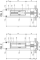
FIGS. 1(A) and 1(B). FIGS. 1(A) and 1(B) are explanatory views illustrating the configuration of a liquid discharge head according to a first embodiment of the present embodiment.FIG. 1(A) is a schematic cross-sectional view of a liquid discharge head illustrating a state where a nozzle is closed, andFIG. 1(B) is a schematic cross-sectional view of the liquid discharge head illustrating a state where the nozzle is opened. - A liquid discharge head 100 (thereinafter, referred to as a head) includes a
housing 110 and anozzle plate 101 attached to one end portion of thehousing 110. - The
housing 110 includes multiple divided sub-housings, and in the present embodiment, thehousing 110 includes three sub-housings, that is, afirst housing 110a, asecond housing 110b, and athird housing 110c. - A
nozzle plate 101 is attached to a lower end portion of thethird housing 110c, and anozzle 102 that discharges a liquid is formed on thenozzle plate 101. Thethird housing 110c includes aliquid inlet 113 for feeding the liquid into the head, aliquid chamber 114 for temporarily storing the liquid fed from theliquid inlet 113, and aliquid outlet 115 for feeding the liquid out of the head. - The
second housing 110b is joined to the end portion of thethird housing 110c on a side opposite to a side where thenozzle plate 101 is attached. Thesecond housing 110b includes abearing 135 that supports aneedle valve 131 described later so as to be movable in the opening and closing direction of thenozzle 102. - The
first housing 110a is joined to an end portion of thesecond housing 110b on a side opposite to a joint side with thethird housing 110c. Thefirst housing 110a stores anactuator 132. The configuration of theactuator 132 is not particularly limited as long as it can be displaced in a vertical direction inFIGS. 1(A) and 1(B) by applying a voltage, but in the present embodiment, a piezoelectric element that expands and contracts by voltage application is used as theactuator 132. Theneedle valve 131 and afixing member 118 are provided at both end portions in the displacement direction (expansion/contraction direction) of theactuator 132 via anelastic member 133. - The
elastic member 133 includes aframe portion 133a formed so as to surround theactuator 132, aspring portion 133b provided in a part of theframe portion 133a, and contactportions actuator 132. Theactuator 132 is sandwiched between thecontact portion 133c and thecontact portion 133d by the contraction force of thespring portion 133b, and is supported by theelastic member 133. - One end of the
needle valve 131 is joined to a lower portion (opposite side of thecontact portion 133d) of theframe portion 133a of theelastic member 133, and the other end of theneedle valve 131 is provided so as to be able to contact thenozzle 102 in thenozzle plate 101. - The
fixing member 118 contacts an upper portion (opposite side of thecontact portion 133c) of theframe portion 133a of theelastic member 133, and thefixing member 118 is secured to thefirst housing 110a by afixing portion 118a. That is, thefixing member 118 forms a securing point such that theelastic member 133 cannot move upward by the displacement (expansion and contraction) of theactuator 132. - As described above, the
needle valve 131 and theactuator 132 are coaxially disposed via theelastic member 133, that is, disposed in series in a liquid discharge direction. Note that theelastic member 133 is not necessarily formed as an integrated member, and for example, theelastic member 133 may be configured by connecting theframe portion 133a and thespring portion 133b prepared as separate members. It is preferable to use a low expansion metal such as stainless steel or Invar for theelastic member 133. - A
heat transfer layer 139 is provided between theactuator 132 and thecontact portion 133d of theelastic member 133 and between theactuator 132 and thecontact portion 133c of theelastic member 133. The configuration of theheat transfer layer 139 is not particularly limited as long as it can efficiently dissipate the heat of theactuator 132. For example, theheat transfer layer 139 is formed of a sheet material or a film material made of heat dissipating silicone, and is also formed by applying grease-like heat dissipating silicone obtained by blending a powder having high thermal conductivity with silicone oil. - In the first embodiment, the
elastic member 133 may not be provided. In this case, theheat transfer layer 139 is provided between theactuator 132 and theneedle valve 131 and between theactuator 132 and thefixing member 118. - Here, the
needle valve 131 is an example of a "valve", and theactuator 132 is an example of a "driver". - In the above configuration, when a predetermined drive voltage is applied to the
actuator 132, theactuator 132 contracts by ΔL from a position illustrated inFIG. 1(A) and changes to a position illustrated inFIG. 1(B) . As a result, theelastic member 133 also deforms in a contraction direction, and theneedle valve 131 attached to theelastic member 133 moves in a direction forming a gap G with respect to thenozzle plate 101. By the movement of theneedle valve 131, thenozzle 102 is opened, and a fluid pressurized and supplied to theliquid chamber 114 is discharged as a droplet D from thenozzle 102. - Next, distance variation due to the thermal deformation of the liquid discharge head will be described with reference to
FIG. 2. FIG. 2 is an explanatory view of distance variation due to the thermal deformation of the liquid discharge head. - The
actuator 132 generates heat in accordance with the liquid discharge operation, and the heat causes the thermal deformation of the components of thehead 100. When the components of thehead 100 are thermally deformed and theneedle valve 131 does not correctly contact thenozzle plate 101, a gap is generated between theneedle valve 131 and thenozzle plate 101. This gap connects theliquid chamber 114 and thenozzle 102, causing a situation in which the liquid is constantly discharged from thenozzle 102. - In order to prevent such a situation, in the head of the first embodiment, the difference between the thermal fluctuation of the
housing 110 and the thermal fluctuation of the stored member (needle valve 131,actuator 132, fixing member 118) stored in thehousing 110 is configured to be close to 0. Strictly speaking, although thermal deformation also occurs in theelastic member 133, the thickness of theelastic member 133 is small in the longitudinal direction (liquid discharge direction), and the deformation amount is at a level that causes no disadvantage. Therefore, it is ignored here. - The thermal fluctuation of the
housing 110 is, that is, distance fluctuation from the fixingportion 118a in thehousing 110 to the inside of thenozzle plate 101, and is the fluctuation of the length of X + Y + Z inFIG. 2 . Note that X is a length in the liquid discharge direction of the first housing 1 10a, Yis a length in the liquid discharge direction of thesecond housing 110b, and Z is a length in the liquid discharge direction of thethird housing 110c. - The thermal fluctuation of the stored member stored in the
housing 110 is, that is, distance fluctuation from the fixingportion 118a to theneedle valve 131, and is the fluctuation of the length of A + M + B inFIG. 2 . A is the length of the fixingmember 118 in the liquid discharge direction, M is the length of theactuator 132 in the liquid discharge direction, and B is the length of theneedle valve 131 in the liquid discharge direction. - In the first embodiment, only M (actuator 132) has a negative thermal expansion (contraction by heat) characteristic, so that materials other than M having a positive thermal expansion (expansion by heat) characteristic are used. That is, the fixing
member 118 and theneedle valve 131 are made of a material whose lengths A and B increase as the temperature rises, and a material having a reverse sign relationship with respect to the linear expansion coefficient of theactuator 132 is used. As a result, the amount by which theactuator 132 contracts due to the temperature rise of theactuator 132 and M decreases can be offset by the amount by which A (fixing member 118) and B (needle valve 131) increase. As a result, it is possible to prevent constant discharge and an increase in discharge caused by the gap between theneedle valve 131 and thenozzle plate 101 due to the temperature rise of long-time drive. - At least one of a
first housing 110a, asecond housing 110b, and athird housing 110c may be made of a material having a low linear expansion coefficient, such as low expansion metal. Examples of the low expansion metal include Invar, which is an alloy of iron and nickel. As a result, it is possible to suppress distance variation (variation of X + Y + Z) that is received by ahousing 110 from the heat generation of theactuator 132. - The
second housing 110b sandwiched between thefirst housing 110a and thethird housing 110c may have heat shielding properties. The heat shielding properties in the present embodiment mean a property of reflecting heat from theactuator 132. The heat shielding properties may be obtained by forming thesecond housing 110b itself with a heat shielding material, or by providing a sheet having a surface to which an aluminum foil, aluminum vapor deposition, or an aluminum film or the like is applied, on a surface of thesecond housing 110b requiring heat shielding. As a result, when thehousing 110 is divided into multiple sub-housings, the processing accuracy of theentire housing 110 can be improved, and the distance variation (variation of X + Y + Z) of thehousing 110 can be suppressed by sandwiching the housing having heat shielding properties. That is, since thesecond housing 110b bounces the heat, the heat is less likely to be transferred to thethird housing 110c, and the fluctuation of Z can be made substantially 0. - Since the
nozzle 102 on thenozzle plate 101 is required to be processed with high accuracy, it is desirable to process thenozzle plate 101 alone. In this case, it is necessary to chemically adhere thenozzle plate 101 on which thenozzle 102 is formed to thethird housing 110c later. In the configuration in which thenozzle plate 101 is adhered to thethird housing 110c later as described above, thethird housing 110c and thenozzle plate 101 are preferably formed of the same material. As a result, it is possible to suppress the positional displacement of thenozzle plate 101 with respect to thethird housing 110c due to thermal fluctuation. - As described above, according to the first embodiment, in the
head 100 including theactuator 132 having a negative thermal expansion characteristic and the members around the actuator having a positive thermal expansion characteristic, the thermal displacement of the contact portion between thenozzle 102 provided on thehousing 110 side and theneedle valve 131 connected to theactuator 132 can be brought close to 0. - Although the configuration in which the
actuator 132 has a negative thermal expansion characteristic (negative linear expansion coefficient) and the fixingmember 118 and theneedle valve 131 have a positive thermal expansion characteristic (positive linear expansion coefficient) has been described above, if the linear expansion coefficient of theactuator 132 and the linear expansion coefficients of the fixingmember 118 and theneedle valve 131 have opposite signs, it is possible to obtain a similar effect of bringing the thermal displacement of the contact portion between thenozzle 102 and theneedle valve 131 close to 0. For example, theactuator 132 may be configured to have a positive thermal expansion characteristic (positive linear expansion coefficient), and the fixingmember 118 and theneedle valve 131 may be configured to have a negative thermal expansion characteristic (negative linear expansion coefficient). - As described above, the present embodiment includes the
housing 110, thenozzle plate 101 attached to thehousing 110 and formed with thenozzle 102 that discharges a liquid, theneedle valve 131 that is stored in thehousing 110 and opens and closes thenozzle 102, theactuator 132 that is provided at the end portion in the opening and closing direction of theneedle valve 131 and drives theneedle valve 131, and the fixingmember 118 that is provided at the end portion in the driving direction of theactuator 132 and is secured to thehousing 110. The linear expansion coefficient of theactuator 132 and the linear expansion coefficients of theneedle valve 131 and the fixingmember 118 have a reverse sign relationship, and theactuator 132 and theneedle valve 131, and theactuator 132 and the fixingmember 118 are connected via theheat transfer layer 139. - As a result, the fluctuation of the member due to the heat generation of the
actuator 132 can be suppressed, and the target discharge state can be maintained. - As described above, the
housing 110 is divided into multiple (three in the present embodiment) sub-housings, and at least one of the multiple divided sub-housings 110a, 110b, and 110c is made of Invar. - As a result, it is possible to suppress distance variation that is received by the
housing 110 from the heat generation of theactuator 132. - As described above, the
housing 110 is divided into three or more sub-housings, and the intermediate sub-housing (second housing 110b) among the multiple sub-housings 110a, 110b, and 110c has heat shielding properties. - As a result, the
second housing 110b bounces heat and makes it difficult to transmit the heat to thethird housing 110c, so that the variation of thethird housing 110c can be made substantially 0. - As described above, the
housing 110 and thenozzle plate 101 are chemically adhered, and thehousing 110 and thenozzle plate 101 are made of the same material. In particular, thethird housing 110c to which thenozzle plate 101 is adhered and thenozzle plate 101 are made of the same material. - As a result, it is possible to suppress the positional displacement of the
nozzle plate 101 with respect to thethird housing 110c due to thermal fluctuation. -
FIG. 3 is an explanatory view illustrating the configuration of a liquid discharge head according to a second embodiment of the present embodiment. - The second embodiment is different from the first embodiment in that an
adjuster 137 is provided at an end portion in an expansion/contraction direction which is the driving direction of anactuator 132. Theactuator 132 and theadjuster 137 are coaxially disposed, that is, in series in a liquid discharge direction. Theadjuster 137 suppresses the thermal contraction of M due to the heat generation of theactuator 132 by using a material having a linear expansion coefficient in a reverse sign relationship with theactuator 132. As a result, the variation in the entire length of A + M + B can be reduced. - At least one of a
first housing 110a, asecond housing 110b, and athird housing 110c may be made of a material having a low linear expansion coefficient, such as low expansion metal. Examples of the low expansion metal include Invar, which is an alloy of iron and nickel. As a result, it is possible to suppress distance variation (variation of X + Y + Z) that is received by ahousing 110 from the heat generation of theactuator 132. - The
second housing 110b sandwiched between thefirst housing 110a and thethird housing 110c may have heat shielding properties. The heat shielding properties in the present embodiment mean a property of reflecting heat from theactuator 132. The heat shielding properties may be obtained by forming thesecond housing 110b itself with a heat shielding material, or by providing a sheet having a surface to which an aluminum foil, aluminum vapor deposition, or an aluminum film or the like is applied, on a surface of thesecond housing 110b requiring heat shielding. As a result, when thehousing 110 is divided into multiple sub-housings, the processing accuracy of theentire housing 110 can be improved, and the distance variation (variation of X + Y + Z) of thehousing 110 can be suppressed by sandwiching the housing having heat shielding properties. That is, since thesecond housing 110b bounces the heat, the heat is less likely to be transferred to thethird housing 110c, and the fluctuation of Z can be made substantially 0. - Since the
nozzle 102 on thenozzle plate 101 is required to be processed with high accuracy, it is desirable to process thenozzle plate 101 alone. In this case, it is necessary to chemically adhere thenozzle plate 101 on which thenozzle 102 is formed to thethird housing 110c later. In the configuration in which thenozzle plate 101 is adhered to thethird housing 110c later as described above, thethird housing 110c and thenozzle plate 101 are preferably formed of the same material. As a result, it is possible to suppress the positional displacement of thenozzle plate 101 with respect to thethird housing 110c due to thermal fluctuation. - As described above, according to the second embodiment, in the
head 100 including theactuator 132 having a negative thermal expansion characteristic and the members around the actuator having a positive thermal expansion characteristic, the thermal displacement of the contact portion between thenozzle 102 provided on thehousing 110 side and theneedle valve 131 connected to theactuator 132 can be brought close to 0. - Although the configuration in which the
actuator 132 has a negative thermal expansion characteristic (negative linear expansion coefficient) and theadjuster 137 has a positive thermal expansion characteristic (positive linear expansion coefficient) has been described above, if the linear expansion coefficient of theactuator 132 and the linear expansion coefficient of theadjuster 137 have opposite signs, it is possible to obtain a similar effect of bringing the thermal displacement of the contact portion between thenozzle 102 and theneedle valve 131 close to 0. For example, theactuator 132 may be configured to have a positive thermal expansion characteristic (positive linear expansion coefficient), and theadjuster 137 may be configured to have a negative thermal expansion characteristic (negative linear expansion coefficient). - As described above, the present embodiment includes the
housing 110, thenozzle plate 101 attached to thehousing 110 and formed with thenozzle 102 that discharges a liquid, theneedle valve 131 that is stored in thehousing 110 and opens and closes thenozzle 102, theactuator 132 that is provided at the end portion in the opening and closing direction of theneedle valve 131 and drives theneedle valve 131, theadjuster 137 attached to the end portion in the driving direction of theactuator 132, and the fixingmember 118 that is provided at the end portion of theadjuster 137 and secured to thehousing 110. The linear expansion coefficient of theactuator 132 and the linear expansion coefficients of theneedle valve 131, theadjuster 137, and the fixingmember 118 have a reverse sign relationship. - As a result, the fluctuation of the member due to the heat generation of the
actuator 132 can be suppressed, and the target discharge state can be maintained. - As described above, the
housing 110 is divided into multiple (three in the present embodiment) sub-housings, and at least one of the multiple divided sub-housings 110a, 110b, and 110c is made of Invar. - As a result, it is possible to suppress distance variation that is received by the
housing 110 from the heat generation of theactuator 132. - As described above, the
housing 110 is divided into three or more sub-housings, and the intermediate sub-housing (second housing 110b) among the multiple sub-housings 110a, 110b, and 110c has heat shielding properties. - As a result, the
second housing 110b bounces heat and makes it difficult to transmit the heat to thethird housing 110c, so that the variation of thethird housing 110c can be made substantially 0. - As described above, the
housing 110 and thenozzle plate 101 are chemically adhered, and thehousing 110 and thenozzle plate 101 are made of the same material. In particular, thethird housing 110c to which thenozzle plate 101 is adhered and thenozzle plate 101 are made of the same material. - As a result, it is possible to suppress the positional displacement of the
nozzle plate 101 with respect to thethird housing 110c due to thermal fluctuation. -
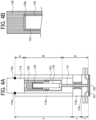
FIGS. 4A and 4B are explanatory views illustrating the configuration of a liquid discharge head according to a third embodiment of the present embodiment.FIG. 4A is a schematic cross-sectional view of the liquid discharge head, andFIG. 4B is an enlarged view of a joint portion between an actuator and an adjuster. - The third embodiment is different from the second embodiment in that an
adjuster 138 provided at the end portion of anactuator 132 is joined so as to cover the end portion of theactuator 132. In the joining of theactuator 132 and theadjuster 138, as illustrated inFIG. 4B , ajoint portion 138a is preferably only a surface intersecting with an expansion/contraction direction so as not to hinder the expansion/contraction operation of theactuator 132. - A
heat transfer layer 139 is provided in a gap between the actuator 132 and theadjuster 138 excluding thejoint portion 138a. The configuration of theheat transfer layer 139 is not particularly limited as long as it can efficiently dissipate the heat of theactuator 132. For example, theheat transfer layer 139 is formed of a sheet material or a film material made of heat dissipating silicone, and is also formed by applying grease-like heat dissipating silicone obtained by blending a powder having high thermal conductivity with silicone oil. As a result, the heat of theactuator 132 is more easily transferred to theadjuster 138, and the thermal contraction of M due to the heat generation of theactuator 132 can be suppressed. - At least one of a
first housing 110a, asecond housing 110b, and athird housing 110c may be made of a material having a low linear expansion coefficient, such as low expansion metal. Examples of the low expansion metal include Invar, which is an alloy of iron and nickel. As a result, it is possible to suppress distance variation (variation of X + Y + Z) that is received by ahousing 110 from the heat generation of theactuator 132. - The
second housing 110b sandwiched between thefirst housing 110a and thethird housing 110c may have heat shielding properties. The heat shielding properties in the present embodiment mean a property of reflecting heat from theactuator 132. The heat shielding properties may be obtained by forming thesecond housing 110b itself with a heat shielding material, or by providing a sheet having a surface to which an aluminum foil, aluminum vapor deposition, or an aluminum film or the like is applied, on a surface of thesecond housing 110b requiring heat shielding. As a result, when thehousing 110 is divided into multiple sub-housings, the processing accuracy of theentire housing 110 can be improved, and the distance variation (variation of X + Y + Z) of thehousing 110 can be suppressed by sandwiching the housing having heat shielding properties. That is, since thesecond housing 110b bounces the heat, the heat is less likely to be transferred to thethird housing 110c, and the fluctuation of Z can be made substantially 0. - Since the
nozzle 102 on thenozzle plate 101 is required to be processed with high accuracy, it is desirable to process thenozzle plate 101 alone. In this case, it is necessary to chemically adhere thenozzle plate 101 on which thenozzle 102 is formed to thethird housing 110c later. In the configuration in which thenozzle plate 101 is adhered to thethird housing 110c later as described above, thethird housing 110c and thenozzle plate 101 are preferably formed of the same material. As a result, it is possible to suppress the positional displacement of thenozzle plate 101 with respect to thethird housing 110c due to thermal fluctuation. - As described above, according to the third embodiment, in the
head 100 including theactuator 132 having a negative thermal expansion characteristic and the members around the actuator having a positive thermal expansion characteristic, the thermal displacement of the contact portion between thenozzle 102 provided on thehousing 110 side and theneedle valve 131 connected to theactuator 132 can be brought close to 0. - Although the configuration in which the
actuator 132 has a negative thermal expansion characteristic (negative linear expansion coefficient) and theadjuster 137 has a positive thermal expansion characteristic (positive linear expansion coefficient) has been described above, if the linear expansion coefficient of theactuator 132 and the linear expansion coefficient of theadjuster 137 have opposite signs, it is possible to obtain a similar effect of bringing the thermal displacement of the contact portion between thenozzle 102 and theneedle valve 131 close to 0. For example, theactuator 132 may be configured to have a positive thermal expansion characteristic (positive linear expansion coefficient), and theadjuster 137 may be configured to have a negative thermal expansion characteristic (negative linear expansion coefficient). - As described above, the present embodiment includes the
housing 110, thenozzle plate 101 attached to thehousing 110 and formed with thenozzle 102 that discharges a liquid, theneedle valve 131 that is stored in thehousing 110 and opens and closes thenozzle 102, theactuator 132 that is provided at the end portion in the opening and closing direction of theneedle valve 131 and drives theneedle valve 131, theadjuster 138 attached to the end portion in the driving direction of theactuator 132, and the fixingmember 118 that is provided at the end portion of theadjuster 138 and secured to thehousing 110. The linear expansion coefficient of theactuator 132 and the linear expansion coefficients of theneedle valve 131, theadjuster 138, and the fixingmember 118 have a reverse sign relationship. - As a result, the fluctuation of the member due to the heat generation of the
actuator 132 can be suppressed, and the target discharge state can be maintained. - As described above, the
actuator 132 and theadjuster 138 are connected via theheat transfer layer 139. - As a result, the heat of the
actuator 132 is more easily transferred to theadjuster 138, and the thermal contraction due to the heat generation of theactuator 132 can be suppressed. - As described above, the
housing 110 is divided into multiple (three in the present embodiment) sub-housings, and at least one of the multiple divided sub-housings 110a, 110b, and 110c is made of Invar. - As a result, it is possible to suppress distance variation that is received by the
housing 110 from the heat generation of theactuator 132. - As described above, the
housing 110 is divided into three or more sub-housings, and the intermediate sub-housing (second housing 110b) among the multiple sub-housings 110a, 110b, and 110c has heat shielding properties. - As a result, the
second housing 110b bounces heat and makes it difficult to transmit the heat to thethird housing 110c, so that the variation of thethird housing 110c can be made substantially 0. - As described above, the
housing 110 and thenozzle plate 101 are chemically adhered, and thehousing 110 and thenozzle plate 101 are made of the same material. In particular, thethird housing 110c to which thenozzle plate 101 is adhered and thenozzle plate 101 are made of the same material. - As a result, it is possible to suppress the positional displacement of the
nozzle plate 101 with respect to thethird housing 110c due to thermal fluctuation. - Next, an application example will be described with reference to
FIG. 5. FIG. 5 is an explanatory view illustrating the application example. - As illustrated in
FIG. 5 , ahead module 700 includes multiple (eight in this example) heads 100 in ahousing 710. Thehousing 710 includes asupply port 711 for supplying a liquid into thehousing 710, asupply path 712 connecting thesupply port 711 and aliquid inlet 713, and aliquid outlet 715 provided on the opposite side of theliquid inlet 713 across aliquid chamber 714. Thehousing 710 includes acollection port 717 for collecting the liquid in thehousing 710, and acollection path 716 connecting thecollection port 717 and theliquid outlet 715. - For the
multiple heads 100,FIG. 5 illustrates the head illustrated in the above-described first embodiment, but it is of course possible to implement the head described in the second embodiment or the third embodiment. The basic configuration of thehead 100 is similar to that described inFIGS. 1(A) and1(B) to 4A and4B , and inFIG. 5 , corresponding elements are denoted by reference numerals in the 700 series. - In the present application example, the eight
heads 100 are provided such thatrespective nozzles 702 are arranged at substantially equal intervals in one direction (left-right direction inFIG. 5 ). Each of theheads 100 is provided to extend in the vertical direction so as to discharge the liquid downward from thenozzles 702 in the lower part ofFIG. 5 . - The
liquid chamber 714 of eachhead 100 is provided to penetrate so that the liquid flows from one side (left side inFIG. 5 ) to the other side (right side inFIG. 5 ) in the arrangement direction of the eight heads 100. - Next, an application example of the
head module 700 described inFIG. 5 will be described with reference toFIGS. 6 and7 .FIG. 6 is an overall perspective view illustrating an example of a carriage, andFIG. 7 is an overall perspective view illustrating an example of a liquid discharge apparatus on which the carriage ofFIG. 6 is mounted.FIG. 6 illustrates acarriage 801 mounted on aliquid discharge apparatus 800 illustrated inFIG. 7 as viewed from aliquid discharge object 1000 side. - The
carriage 801 includes ahead holder 80. Thecarriage 801 is movable in a Z direction (positive side and negative side) along a Z-axis rail 804 by power from a first Z-direction driving unit 807 described later. - The
head holder 80 is movable in the Z-direction (positive side and negative side) with respect to thecarriage 801 by power from a second Z-direction driving unit 808 described later. Thehead holder 80 includes ahead securing plate 80a to which thehead module 700 is attached. - In the present application example, a configuration in which six
head modules 700 described inFIG. 5 are attached to thehead securing plate 80a is exemplified, and the sixhead modules 700 are provided side by side in a stacked manner. - Each of the
head modules 700 includesmultiple nozzles 702. Note that the type and number of colors of inks used in thehead modules 700 may be different for each of the head modules, or all the inks may have the same color. For example, when theliquid discharge apparatus 800 is a coating apparatus using a single color, the inks used in the sixhead modules 700 may have the same color. The number of thehead modules 700 is not limited to 6. The number may be more than 6 or less than 6. - The
head module 700 is secured to thehead securing plate 80a in a state where a nozzle row (a row formed by eight nozzles 702) of each head module intersects with a horizontal plane (X-Z plane) and the arrangement direction of themultiple nozzles 702 is inclined with respect to an X axis. In this state, thenozzle 702 discharges the liquid in a direction (positive side in the Z direction) intersecting with the gravity direction. - A
printing apparatus 800 as an example of the liquid discharge apparatus illustrated inFIG. 7 is installed to face theliquid discharge object 1000. Theprinting apparatus 800 includes anX-axis rail 802, a Y-axis rail 803 intersecting with theX-axis rail 802, and a Z-axis rail 804 intersecting with theX-axis rail 802 and the Y-axis rail 803. - The Y-
axis rail 803 holds theX-axis rail 802 such that theX-axis rail 802 is movable in a Y direction (positive side and negative side). TheX-axis rail 802 holds the Z-axis rail 804 such that the Z-axis rail 804 is movable in an X direction (positive side and negative side). The Z-axis rail 804 holds thecarriage 801 such that thecarriage 801 is movable in the Z direction (positive side and negative side). - The
printing apparatus 800 includes a first Z-direction driving unit 807 that causes thecarriage 801 to move in the Z direction along the Z-axis rail 804, and anX-direction driving unit 805 that causes the Z-axis rail 804 to move in the X direction along theX-axis rail 802. Theprinting apparatus 800 includes a Y-direction driving unit 806 that causes theX-axis rail 802 to move in the Y direction along the Y-axis rail 803. Theprinting apparatus 800 further includes a second Z-direction driving unit 808 that causes thehead holder 80 to move in the Z direction with respect to thecarriage 801. - The
printing apparatus 800 configured as described above discharges ink as an example of a liquid from the head module 700 (seeFIG. 6 ) provided in thehead holder 80 to perform printing on theliquid discharge object 1000 while causing thecarriage 801 to move in the X direction, the Y direction, and the Z direction. The movement of thecarriage 801 and thehead holder 80 in the Z direction does not necessarily mean parallel to the Z direction, and may be oblique movement as long as the movement includes at least a component in the Z direction. - In
FIG. 6 , the surface shape of theliquid discharge object 1000 is a flat surface, but the surface shape of theliquid discharge object 1000 may be a surface close to a vertical direction such as a vehicle body of a vehicle or a truck, or a body of an aircraft, a surface having a large radius of curvature, or a surface having some irregularities. - In the present embodiment, examples of the liquid include solutions, suspensions, and emulsions containing solvents such as water and organic solvents, colorants such as dyes and pigments, function-imparting materials such as polymerizable compounds, resins, and surfactants, biocompatible materials such as deoxyribonucleic acid (DNA), amino acids, proteins, and calcium, and edible materials such as natural pigments, and the like.
- These can be used for, for example, inkjet inks, paint coating materials, surface treatment liquids, constituent elements of electronic elements and light emitting elements, liquids for forming electronic circuit resist patterns, and material liquids for three-dimensional modeling, and the like.
- The liquid discharge apparatus according to the present embodiment is not limited to the form of the printing apparatus described above. For example, the head module (or head) of the present embodiment may be attached to the tip of a robot arm of an articulated robot capable of freely moving like a human arm by multiple joints. The liquid discharge apparatus is not limited to the apparatus configured to cause the head to move with respect to the liquid discharge object. The head and the liquid discharge object only need to be relatively movable, and the liquid discharge object may be configured to move with respect to the head.
- The above description is an example, and the present embodiment has specific effects for each of the following aspects.
- A liquid discharge head as a first aspect includes a housing (for example, a housing 110), a nozzle plate (for example, a nozzle plate 101) attached to the housing and provided with a nozzle for discharging a liquid, a valve (for example, a needle valve 131) that is stored in the housing and opens and closes the nozzle, a driver (for example, an actuator 132) that is provided at an end portion of the valve in an opening and closing direction and drives the valve; and a fixing member (for example, a fixing member 118) provided at an end portion of the driver in a driving direction and secured to the housing, wherein a linear expansion coefficient of the driver and linear expansion coefficients of the valve and the fixing member have a reverse sign relationship, and the driver and the valve, and the driver and the fixing member are connected via a heat transfer layer (for example, a heat transfer layer 139).
- A liquid discharge head as a second aspect includes a housing (for example, a housing 110), a nozzle plate (for example, a nozzle plate 101) attached to the housing and provided with a nozzle for discharging a liquid, a valve (for example, a needle valve 131) that is stored in the housing and opens and closes the nozzle, a driver (for example, an actuator 132) that is provided at an end portion of the valve in an opening and closing direction and drives the valve, an adjuster (for example, an adjuster 137) attached to an end portion of the driver in a driving direction, and a fixing member (for example, a fixing member 118) provided at an end portion of the adjuster and secured to the housing, wherein a linear expansion coefficient of the driver and linear expansion coefficients of the valve, the adjuster, and the fixing member have a reverse sign relationship.
- According to the first aspect and the second aspect, it is possible to suppress the fluctuation of the member due to the heat generation of the driver and maintain the target discharge state.
- In the liquid discharge head as a third aspect, in the second aspect, the driver (for example, the actuator 132) and the adjuster (for example, the adjuster 138) are connected via a heat transfer layer (for example, a heat transfer layer 139).
- According to the third aspect, the heat of the driver is more easily transferred to the adjuster, and the thermal contraction of the driver itself due to the heat generation of the driver can be suppressed.
- In the liquid discharge head as a fourth aspect, in the first aspect or the second aspect, the housing (for example, the housing 110) is divided into multiple sub-housings, and at least one of the multiple divided sub-housings (for example, a
first housing 110a, asecond housing 110b, and athird housing 110c) is made of Invar. - According to the fourth aspect, it is possible to suppress distance variation that is received by the housing from the heat generation of the driver.
- In the liquid discharge head as a fifth aspect, in the first aspect or the second aspect, the housing (for example, the housing 110) is divided into three or more sub-housings, and an intermediate sub-housing (for example, a
second casing 110b) among the multiple sub-housings (for example, afirst housing 110a, asecond housing 110b, and athird housing 110c) has heat shielding properties. - According to the fifth aspect, the intermediate housing bounces heat and makes it difficult to transmit the heat to the downstream housing, so that the fluctuation of the downstream housing can be made substantially zero.
- In the liquid discharge head as a sixth aspect, in the first aspect or the second aspect, the housing (for example, the housing 110) and the nozzle plate (for example, the nozzle plate 101) are chemically adhered, and the housing and the nozzle plate are made of the same material.
- According to the sixth aspect, it is possible to suppress the positional displacement of the nozzle plate with respect to the housing due to thermal fluctuation.
- A liquid discharge head (100) includes: a housing (110); a nozzle plate (101) attached to the housing (110), the nozzle plate (101) having a nozzle (102) from which a liquid is to be discharged; a valve (131) in the housing (110), the valve (131) configured to move in an opening and closing direction and openably close the nozzle (102); a driver (132) having one end coupled to the valve (131) in the opening and closing direction, the driver (132) configured to drive the valve (131); and a fixing member (118) fixed to the housing (110) and coupled to another end of the driver (132) in the opening and closing direction, wherein the driver (132) has a first linear expansion coefficient, each of the valve (131) and the fixing member (118) has a second linear expansion coefficient, the first linear expansion coefficient and the second linear expansion coefficient are reversed in positivity and negativity, and the driver (132) is coupled to each of the valve (131) and the fixing member (118) via a heat transfer layer (139).
- The liquid discharge head (100) according to claim 7, further includes an adjuster (137, 138) between the fixing member and said another end of the driver, wherein the driver (132) has a first linear expansion coefficient, each of the valve (131), the adjuster (137, 138), and the fixing member (118) has a second linear expansion coefficient, and the first linear expansion coefficient and the second linear expansion coefficient are reversed in positivity and negativity.
- In the liquid discharge head (100) according to claim 8, the driver and the adjuster (137, 138) are coupled via the heat transfer layer (139).
- In the liquid discharge head (100) according to claim 7 or 8, the housing (110) includes multiple sub-housings, and at least one of the multiple sub-housings is made of Invar.
- In the liquid discharge head (100) according to claim 7 or 8, the housing (110) includes three or more sub-housings, and the three or more sub-housings includes an intermediate sub-housing has heat shielding property.
- In the liquid discharge head (100) according to claim 7 or 8, the housing (110) and the nozzle plate (101) are chemically adhered, and the housing (110) and the nozzle plate (101) are made of the same material.
- In the liquid discharge head (100) according to claim 7 or 8, the adjuster covers said another end of the driver.
- A head module (700) includes multiple liquid discharge heads (100) including the liquid discharge head according to any one of claims 7 to 13.
- A liquid discharge apparatus includes the liquid discharge head (100) according to any one of claims 7 to 13.
- A liquid discharge apparatus includes the head module (700) according to claim 14.
- A liquid discharge head (100) includes: a housing (110); a nozzle plate (101) attached to the housing (110), the nozzle plate (101) having a nozzle (102) from which a liquid is to be discharged; a valve (131) in the housing (110), the valve (131) configured to move in an opening and closing direction and openably close the nozzle (102); a driver (132) having one end coupled to the valve (131) in the opening and closing direction, the driver configured to drive the valve (131); a fixing member (118) fixed to the housing (110) and coupled to another end of the driver (132) in the opening and closing direction; and an adjuster (137, 138) between the fixing member (118) and said another end of the driver (132), wherein the driver (132) has a first linear expansion coefficient, each of the valve (131), the adjuster )137, 138), and the fixing member (118) has a second linear expansion coefficient, and the first linear expansion coefficient and the second linear expansion coefficient are reversed in positivity and negativity.
Claims (11)
- A liquid discharge head (100) comprising:a housing (110);a nozzle plate (101) attached to the housing (110), the nozzle plate (101) having a nozzle (102) from which a liquid is to be discharged;a valve (131) in the housing (110), the valve (131) configured to move in an opening and closing direction and openably close the nozzle (102);a driver (132) having one end coupled to the valve (131) in the opening and closing direction, the driver (132) configured to drive the valve (131); anda fixing member (118) fixed to the housing (110) and coupled to another end of the driver (132) in the opening and closing direction,wherein the driver (132) has a first linear expansion coefficient,each of the valve (131) and the fixing member (118) has a second linear expansion coefficient,the first linear expansion coefficient and the second linear expansion coefficient are reversed in positivity and negativity, andthe driver (132) is coupled to each of the valve (131) and the fixing member (118) via a heat transfer layer (139).
- The liquid discharge head (100) according to claim 1, further comprising an adjuster (137, 138) between the fixing member and said another end of the driver,wherein the driver (132) has a first linear expansion coefficient,each of the valve (131), the adjuster (137, 138), and the fixing member (118) has a second linear expansion coefficient, andthe first linear expansion coefficient and the second linear expansion coefficient are reversed in positivity and negativity.
- The liquid discharge head (100) according to claim 2,
wherein the driver and the adjuster (137, 138) are coupled via the heat transfer layer (139). - The liquid discharge head (100) according to claim 1 or 2,wherein the housing (110) includes multiple sub-housings, andat least one of the multiple sub-housings is made of Invar.
- The liquid discharge head (100) according to claim 1 or 2,wherein the housing (110) includes three or more sub-housings, andthe three or more sub-housings includes an intermediate sub-housing has heat shielding property.
- The liquid discharge head (100) according to claim 1 or 2,
wherein the housing (110) and the nozzle plate (101) are chemically adhered, and the housing (110) and the nozzle plate (101) are made of the same material. - The liquid discharge head (100) according to claim 2,
wherein the adjuster covers said another end of the driver. - A head module (700) comprising multiple liquid discharge heads (100) comprising the liquid discharge head according to any one of claims 1 to 7.
- A liquid discharge apparatus comprising the liquid discharge head (100) according to any one of claims 1 to 7.
- A liquid discharge apparatus comprising the head module (700) according to claim 8.
- A liquid discharge head (100) comprising:a housing (110);a nozzle plate (101) attached to the housing (110), the nozzle plate (101) having a nozzle (102) from which a liquid is to be discharged;a valve (131) in the housing (110), the valve (131) configured to move in an opening and closing direction and openably close the nozzle (102);a driver (132) having one end coupled to the valve (131) in the opening and closing direction, the driver configured to drive the valve (131);a fixing member (118) fixed to the housing (110) and coupled to another end of the driver (132) in the opening and closing direction; andan adjuster (137, 138) between the fixing member (118) and said another end of the driver (132),wherein the driver (132) has a first linear expansion coefficient,each of the valve (131), the adjuster )137, 138), and the fixing member (118) has a second linear expansion coefficient, andthe first linear expansion coefficient and the second linear expansion coefficient are reversed in positivity and negativity.
Applications Claiming Priority (1)
| Application Number | Priority Date | Filing Date | Title |
|---|---|---|---|
| JP2022085262A JP7857552B2 (en) | 2022-05-25 | 2022-05-25 | Liquid dispensing head, head module, and device for dispensing liquid |
Publications (2)
| Publication Number | Publication Date |
|---|---|
| EP4282659A1 true EP4282659A1 (en) | 2023-11-29 |
| EP4282659B1 EP4282659B1 (en) | 2025-01-01 |
Family
ID=86497849
Family Applications (1)
| Application Number | Title | Priority Date | Filing Date |
|---|---|---|---|
| EP23174518.3A Active EP4282659B1 (en) | 2022-05-25 | 2023-05-22 | Liquid discharge head, head module, and liquid discharge apparatus |
Country Status (4)
| Country | Link |
|---|---|
| US (1) | US12427771B2 (en) |
| EP (1) | EP4282659B1 (en) |
| JP (1) | JP7857552B2 (en) |
| ES (1) | ES3007809T3 (en) |
Citations (3)
| Publication number | Priority date | Publication date | Assignee | Title |
|---|---|---|---|---|
| US4803501A (en) * | 1985-05-13 | 1989-02-07 | Swedot System Ab | Device for generating fluid drops |
| JP2010241003A (en) | 2009-04-07 | 2010-10-28 | Seiko Epson Corp | Droplet discharge head |
| JP2022073547A (en) * | 2020-11-02 | 2022-05-17 | 株式会社リコー | Liquid discharge head and liquid discharge device |
Family Cites Families (17)
| Publication number | Priority date | Publication date | Assignee | Title |
|---|---|---|---|---|
| US5065978A (en) * | 1988-04-27 | 1991-11-19 | Dragerwerk Aktiengesellschaft | Valve arrangement of microstructured components |
| JP4100952B2 (en) | 2002-04-15 | 2008-06-11 | マークテック株式会社 | Marking head and dot marking device |
| JP4123897B2 (en) | 2002-10-28 | 2008-07-23 | 株式会社エルエーシー | Inkjet nozzle |
| JP2007050674A (en) | 2005-08-19 | 2007-03-01 | Seiko Epson Corp | Liquid ejecting head unit and liquid ejecting apparatus |
| JP5368122B2 (en) | 2009-01-21 | 2013-12-18 | ノイベルク有限会社 | Liquid ejection device |
| JP2011156338A (en) | 2010-01-08 | 2011-08-18 | Minoru Nakamura | Syringe pump |
| JP5553795B2 (en) | 2010-05-21 | 2014-07-16 | Tdk株式会社 | Liquid dripping device |
| US8820871B2 (en) * | 2010-10-27 | 2014-09-02 | Matthews Resources, Inc. | Valve jet printer with inert plunger tip |
| US8454126B2 (en) * | 2010-12-03 | 2013-06-04 | Videojet Technologies Inc | Print head with electromagnetic valve assembly |
| US20160169180A1 (en) * | 2014-07-09 | 2016-06-16 | Mcalister Technologies, Llc | Integrated fuel injector ignitor having a preloaded piezoelectric actuator |
| JP7103142B2 (en) | 2018-02-24 | 2022-07-20 | 株式会社リコー | Head module, head unit, liquid discharge device |
| JP2019162852A (en) | 2018-03-16 | 2019-09-26 | 株式会社リコー | Head module, liquid discharging device |
| DE102018124662A1 (en) | 2018-10-05 | 2020-04-09 | Vermes Microdispensing GmbH | Dosing system with cooling device |
| JP7326820B2 (en) | 2019-04-03 | 2023-08-16 | 株式会社リコー | Device for ejecting liquid |
| JP7600601B2 (en) | 2020-03-23 | 2024-12-17 | 株式会社リコー | Discharge head, discharge unit, and device for discharging liquid |
| JP7506861B2 (en) | 2020-10-26 | 2024-06-27 | 株式会社リコー | LIQUID EJECTION HEAD AND LIQUID EJECTION APPARATUS |
| JP2023128410A (en) * | 2022-03-03 | 2023-09-14 | 株式会社リコー | Droplet ejection head and droplet ejection device |
-
2022
- 2022-05-25 JP JP2022085262A patent/JP7857552B2/en active Active
-
2023
- 2023-05-15 US US18/197,116 patent/US12427771B2/en active Active
- 2023-05-22 EP EP23174518.3A patent/EP4282659B1/en active Active
- 2023-05-22 ES ES23174518T patent/ES3007809T3/en active Active
Patent Citations (3)
| Publication number | Priority date | Publication date | Assignee | Title |
|---|---|---|---|---|
| US4803501A (en) * | 1985-05-13 | 1989-02-07 | Swedot System Ab | Device for generating fluid drops |
| JP2010241003A (en) | 2009-04-07 | 2010-10-28 | Seiko Epson Corp | Droplet discharge head |
| JP2022073547A (en) * | 2020-11-02 | 2022-05-17 | 株式会社リコー | Liquid discharge head and liquid discharge device |
Also Published As
| Publication number | Publication date |
|---|---|
| ES3007809T3 (en) | 2025-03-20 |
| JP7857552B2 (en) | 2026-05-13 |
| US20230382115A1 (en) | 2023-11-30 |
| US12427771B2 (en) | 2025-09-30 |
| EP4282659B1 (en) | 2025-01-01 |
| JP2023173184A (en) | 2023-12-07 |
Similar Documents
| Publication | Publication Date | Title |
|---|---|---|
| US12502887B2 (en) | Discharge head, discharge unit, and liquid discharge apparatus | |
| US10836190B2 (en) | Head module, head device, and liquid discharge apparatus | |
| US12390993B2 (en) | Three-dimensional-object printing apparatus | |
| JP2023140940A (en) | Droplet ejection head and droplet ejection device | |
| JP7103142B2 (en) | Head module, head unit, liquid discharge device | |
| US10717281B2 (en) | Head module and liquid discharge apparatus | |
| EP4282659B1 (en) | Liquid discharge head, head module, and liquid discharge apparatus | |
| CN117377573B (en) | Liquid discharge head and liquid discharge device | |
| US12343994B2 (en) | Liquid discharge head, head module, liquid discharge unit, and liquid discharge apparatus | |
| JP7594728B2 (en) | LIQUID EJECTION HEAD AND LIQUID EJECTION APPARATUS | |
| EP4371776B1 (en) | Liquid discharge head and liquid discharge apparatus | |
| EP4249263A1 (en) | Droplet discharge head and droplet discharge apparatus | |
| EP4563357A1 (en) | Liquid discharge head and liquid discharge apparatus | |
| US12391043B2 (en) | Liquid discharge head, liquid discharge device, liquid discharge apparatus, and method of manufacturing liquid discharge head | |
| EP4431291A1 (en) | Liquid discharge module and liquid discharge apparatus | |
| JP2022187979A (en) | Liquid discharge head and liquid discharge device | |
| US12528292B2 (en) | Liquid discharge head, liquid discharge head unit, and liquid discharge apparatus | |
| WO2025114792A1 (en) | Liquid discharge head and liquid discharge apparatus | |
| JP7775707B2 (en) | Droplet ejection module, droplet ejection head, and droplet ejection device | |
| JP2023002924A (en) | Head unit, printer, and three-dimensional object printer | |
| US20240198673A1 (en) | Liquid discharge head, liquid discharge unit, and liquid discharge apparatus | |
| JP2025140794A (en) | Liquid discharge head, liquid discharge unit and liquid discharge device |
Legal Events
| Date | Code | Title | Description |
|---|---|---|---|
| PUAI | Public reference made under article 153(3) epc to a published international application that has entered the european phase |
Free format text: ORIGINAL CODE: 0009012 |
|
| STAA | Information on the status of an ep patent application or granted ep patent |
Free format text: STATUS: REQUEST FOR EXAMINATION WAS MADE |
|
| 17P | Request for examination filed |
Effective date: 20230522 |
|
| AK | Designated contracting states |
Kind code of ref document: A1 Designated state(s): AL AT BE BG CH CY CZ DE DK EE ES FI FR GB GR HR HU IE IS IT LI LT LU LV MC ME MK MT NL NO PL PT RO RS SE SI SK SM TR |
|
| GRAP | Despatch of communication of intention to grant a patent |
Free format text: ORIGINAL CODE: EPIDOSNIGR1 |
|
| STAA | Information on the status of an ep patent application or granted ep patent |
Free format text: STATUS: GRANT OF PATENT IS INTENDED |
|
| RIC1 | Information provided on ipc code assigned before grant |
Ipc: B41J 2/14 20060101AFI20240715BHEP |
|
| INTG | Intention to grant announced |
Effective date: 20240807 |
|
| GRAS | Grant fee paid |
Free format text: ORIGINAL CODE: EPIDOSNIGR3 |
|
| GRAA | (expected) grant |
Free format text: ORIGINAL CODE: 0009210 |
|
| STAA | Information on the status of an ep patent application or granted ep patent |
Free format text: STATUS: THE PATENT HAS BEEN GRANTED |
|
| P01 | Opt-out of the competence of the unified patent court (upc) registered |
Free format text: CASE NUMBER: APP_58119/2024 Effective date: 20241024 |
|
| AK | Designated contracting states |
Kind code of ref document: B1 Designated state(s): AL AT BE BG CH CY CZ DE DK EE ES FI FR GB GR HR HU IE IS IT LI LT LU LV MC ME MK MT NL NO PL PT RO RS SE SI SK SM TR |
|
| REG | Reference to a national code |
Ref country code: GB Ref legal event code: FG4D |
|
| REG | Reference to a national code |
Ref country code: CH Ref legal event code: EP |
|
| REG | Reference to a national code |
Ref country code: DE Ref legal event code: R096 Ref document number: 602023001560 Country of ref document: DE |
|
| REG | Reference to a national code |
Ref country code: IE Ref legal event code: FG4D |
|
| REG | Reference to a national code |
Ref country code: ES Ref legal event code: FG2A Ref document number: 3007809 Country of ref document: ES Kind code of ref document: T3 Effective date: 20250320 |
|
| REG | Reference to a national code |
Ref country code: LT Ref legal event code: MG9D |
|
| REG | Reference to a national code |
Ref country code: NL Ref legal event code: MP Effective date: 20250101 |
|
| REG | Reference to a national code |
Ref country code: AT Ref legal event code: MK05 Ref document number: 1755854 Country of ref document: AT Kind code of ref document: T Effective date: 20250101 |
|
| PG25 | Lapsed in a contracting state [announced via postgrant information from national office to epo] |
Ref country code: NL Free format text: LAPSE BECAUSE OF FAILURE TO SUBMIT A TRANSLATION OF THE DESCRIPTION OR TO PAY THE FEE WITHIN THE PRESCRIBED TIME-LIMIT Effective date: 20250101 |
|
| PG25 | Lapsed in a contracting state [announced via postgrant information from national office to epo] |
Ref country code: FI Free format text: LAPSE BECAUSE OF FAILURE TO SUBMIT A TRANSLATION OF THE DESCRIPTION OR TO PAY THE FEE WITHIN THE PRESCRIBED TIME-LIMIT Effective date: 20250101 |
|
| PG25 | Lapsed in a contracting state [announced via postgrant information from national office to epo] |
Ref country code: PL Free format text: LAPSE BECAUSE OF FAILURE TO SUBMIT A TRANSLATION OF THE DESCRIPTION OR TO PAY THE FEE WITHIN THE PRESCRIBED TIME-LIMIT Effective date: 20250101 |
|
| PGFP | Annual fee paid to national office [announced via postgrant information from national office to epo] |
Ref country code: DE Payment date: 20250521 Year of fee payment: 3 |
|
| PG25 | Lapsed in a contracting state [announced via postgrant information from national office to epo] |
Ref country code: IS Free format text: LAPSE BECAUSE OF FAILURE TO SUBMIT A TRANSLATION OF THE DESCRIPTION OR TO PAY THE FEE WITHIN THE PRESCRIBED TIME-LIMIT Effective date: 20250501 Ref country code: NO Free format text: LAPSE BECAUSE OF FAILURE TO SUBMIT A TRANSLATION OF THE DESCRIPTION OR TO PAY THE FEE WITHIN THE PRESCRIBED TIME-LIMIT Effective date: 20250401 |
|
| PGFP | Annual fee paid to national office [announced via postgrant information from national office to epo] |
Ref country code: IT Payment date: 20250531 Year of fee payment: 3 |
|
| PG25 | Lapsed in a contracting state [announced via postgrant information from national office to epo] |
Ref country code: HR Free format text: LAPSE BECAUSE OF FAILURE TO SUBMIT A TRANSLATION OF THE DESCRIPTION OR TO PAY THE FEE WITHIN THE PRESCRIBED TIME-LIMIT Effective date: 20250101 |
|
| PG25 | Lapsed in a contracting state [announced via postgrant information from national office to epo] |
Ref country code: LV Free format text: LAPSE BECAUSE OF FAILURE TO SUBMIT A TRANSLATION OF THE DESCRIPTION OR TO PAY THE FEE WITHIN THE PRESCRIBED TIME-LIMIT Effective date: 20250101 Ref country code: PT Free format text: LAPSE BECAUSE OF FAILURE TO SUBMIT A TRANSLATION OF THE DESCRIPTION OR TO PAY THE FEE WITHIN THE PRESCRIBED TIME-LIMIT Effective date: 20250502 |
|
| PGFP | Annual fee paid to national office [announced via postgrant information from national office to epo] |
Ref country code: FR Payment date: 20250528 Year of fee payment: 3 |
|
| PG25 | Lapsed in a contracting state [announced via postgrant information from national office to epo] |
Ref country code: GR Free format text: LAPSE BECAUSE OF FAILURE TO SUBMIT A TRANSLATION OF THE DESCRIPTION OR TO PAY THE FEE WITHIN THE PRESCRIBED TIME-LIMIT Effective date: 20250402 Ref country code: BG Free format text: LAPSE BECAUSE OF FAILURE TO SUBMIT A TRANSLATION OF THE DESCRIPTION OR TO PAY THE FEE WITHIN THE PRESCRIBED TIME-LIMIT Effective date: 20250101 |
|
| PG25 | Lapsed in a contracting state [announced via postgrant information from national office to epo] |
Ref country code: AT Free format text: LAPSE BECAUSE OF FAILURE TO SUBMIT A TRANSLATION OF THE DESCRIPTION OR TO PAY THE FEE WITHIN THE PRESCRIBED TIME-LIMIT Effective date: 20250101 |
|
| PG25 | Lapsed in a contracting state [announced via postgrant information from national office to epo] |
Ref country code: CZ Free format text: LAPSE BECAUSE OF FAILURE TO SUBMIT A TRANSLATION OF THE DESCRIPTION OR TO PAY THE FEE WITHIN THE PRESCRIBED TIME-LIMIT Effective date: 20250101 |
|
| PG25 | Lapsed in a contracting state [announced via postgrant information from national office to epo] |
Ref country code: SE Free format text: LAPSE BECAUSE OF FAILURE TO SUBMIT A TRANSLATION OF THE DESCRIPTION OR TO PAY THE FEE WITHIN THE PRESCRIBED TIME-LIMIT Effective date: 20250101 |
|
| REG | Reference to a national code |
Ref country code: DE Ref legal event code: R097 Ref document number: 602023001560 Country of ref document: DE |
|
| PG25 | Lapsed in a contracting state [announced via postgrant information from national office to epo] |
Ref country code: SM Free format text: LAPSE BECAUSE OF FAILURE TO SUBMIT A TRANSLATION OF THE DESCRIPTION OR TO PAY THE FEE WITHIN THE PRESCRIBED TIME-LIMIT Effective date: 20250101 |
|
| PGFP | Annual fee paid to national office [announced via postgrant information from national office to epo] |
Ref country code: ES Payment date: 20250630 Year of fee payment: 3 |
|
| PG25 | Lapsed in a contracting state [announced via postgrant information from national office to epo] |
Ref country code: DK Free format text: LAPSE BECAUSE OF FAILURE TO SUBMIT A TRANSLATION OF THE DESCRIPTION OR TO PAY THE FEE WITHIN THE PRESCRIBED TIME-LIMIT Effective date: 20250101 |
|
| PG25 | Lapsed in a contracting state [announced via postgrant information from national office to epo] |
Ref country code: EE Free format text: LAPSE BECAUSE OF FAILURE TO SUBMIT A TRANSLATION OF THE DESCRIPTION OR TO PAY THE FEE WITHIN THE PRESCRIBED TIME-LIMIT Effective date: 20250101 |
|
| PG25 | Lapsed in a contracting state [announced via postgrant information from national office to epo] |
Ref country code: RO Free format text: LAPSE BECAUSE OF FAILURE TO SUBMIT A TRANSLATION OF THE DESCRIPTION OR TO PAY THE FEE WITHIN THE PRESCRIBED TIME-LIMIT Effective date: 20250101 |
|
| PG25 | Lapsed in a contracting state [announced via postgrant information from national office to epo] |
Ref country code: SK Free format text: LAPSE BECAUSE OF FAILURE TO SUBMIT A TRANSLATION OF THE DESCRIPTION OR TO PAY THE FEE WITHIN THE PRESCRIBED TIME-LIMIT Effective date: 20250101 |
|
| PLBE | No opposition filed within time limit |
Free format text: ORIGINAL CODE: 0009261 |
|
| STAA | Information on the status of an ep patent application or granted ep patent |
Free format text: STATUS: NO OPPOSITION FILED WITHIN TIME LIMIT |
|
| 26N | No opposition filed |
Effective date: 20251002 |
|
| PG25 | Lapsed in a contracting state [announced via postgrant information from national office to epo] |
Ref country code: LU Free format text: LAPSE BECAUSE OF NON-PAYMENT OF DUE FEES Effective date: 20250522 |
|
| REG | Reference to a national code |
Ref country code: BE Ref legal event code: MM Effective date: 20250531 |
|
| PG25 | Lapsed in a contracting state [announced via postgrant information from national office to epo] |
Ref country code: MC Free format text: LAPSE BECAUSE OF FAILURE TO SUBMIT A TRANSLATION OF THE DESCRIPTION OR TO PAY THE FEE WITHIN THE PRESCRIBED TIME-LIMIT Effective date: 20250101 |
|
| PG25 | Lapsed in a contracting state [announced via postgrant information from national office to epo] |
Ref country code: IE Free format text: LAPSE BECAUSE OF NON-PAYMENT OF DUE FEES Effective date: 20250522 |
|
| PG25 | Lapsed in a contracting state [announced via postgrant information from national office to epo] |
Ref country code: BE Free format text: LAPSE BECAUSE OF NON-PAYMENT OF DUE FEES Effective date: 20250531 |